Embed Size (px)
Citation preview

1
Laser Direct Drive:Scientific Advances,Technical Achievements,and the Road To Fusion Energy
Presented byJohn SethianNaval Research Laboratory

2
Fusion Energy with Lasers and Direct Drive
Electricityor Hydrogen
Generator
Reactionchamber
Spherical pellet
Pelletfactory
Arrayof
Lasers
Final optics

3
Why we believe direct drive with lasers can lead to an attractive power plant
1. Simplest target physics:
2. Laser (most costly component) is modular
3. Separate components lower cost of development
4. Simple spherical targets:facilitates mass produced “fuel"
5. Power plant studies economically attractive
6. We have made a lot of progress!!

4
We are committed to Direct Drive for the Fusion Energy Mission
Indirect Drive(Chosen path for NIF)
Laser Beamsx-rays
Hohlraum Pellet
Direct Drive(IFE)
Laser Beams
Pellet
• Relaxed laser uniformity requirements
• Complex targets & physics
• Predict moderate energy gain (≤ 40)at 1 MJ laser energy
• Advanced lasers/ target designs overcomeuniformity requirements
• Simpler targets & physics
• Predict Fusion Class Gains (> 140)at lower laser energy (500 kJ - 1 MJ)

5
Two laser options for Direct Drive:KrF and DPPSL Both have potential to meet the IFE requirements
Electra KrF Laser (NRL)λ = 248 nm (fundamental)Gas Laser
See talk by Frank HegelerThursday PM
See talk by Chris EbbersThursday PM
Mercury DPPSL Laser (LLNL)λ = 351 nm (tripled)Solid State Laser

6
We encourage competition.It leads to innovation and a better product.
And leads to it faster
KrFDPSSL

7
KrF lasers have advantages for fusion energy
PHYSICS● Deeper UV (248 nm vs 351 for glass):
-- Greater mass ablation rate and pressure at given intensity-- Higher threshold for deleterious laser plasma instability (LPI) ~1.8x
(so maximum ablation pressure is further increased)
● Focus of KrF beams can be readily "zoomed" to follow imploding pellet-- increases coupling by 30%
● KrF has most uniform pellet illumination .-- 0.2% non-uniformity overlapped beams
ENGINEERING ● Industrial robust technology (used in industry, medical applications)
● Gas laser medium is easy to cool (tough to break gas)
Nike single beam focus

8
Advances and Achievements
• target design• lasers• final optics• target fabrication and engagement• chamber

9
Gain for Fusion Energy
New Direct Drive Designs:Power plant class gains, much smaller laser
1.50 0.5 1 2 2.5 30
100
200
300
Target Gain
Shock ignition, λ=248 nmSoft Conventional Compression (< 300 km/sec)Then spike to shock heat to ignition
Enough for energy…at < 500 kJ
FTF Designs, KrF λ= 248 nmHigher ablation pressure 350 to 450 km/sec
Laser Energy (MJ)
NIF Indirect Drive
Conventional Direct Drive(KrF or DPPSL)~300 km/sec implosion

10
Shock Ignition predicts comparable gains as Fast Ignition… without the complexities
Shock ignitionλ = 248 nm
1.50 0.5 1 2 2.5 30
100
200
300
Target Gain
Fast ignition,λ = 248 nm
Fast ignition,λ = 351 nm
Shock ignition proposed byR Betti, University of Rochester

11
Low aspect ratio pellet helps mitigate hydro instability
Laser IntensitiesPeak main drive ~ 1.5 × 10¹⁵ W/cm2
Igniter pulse is ~1016 W/cm2
DT Ice (fuel)
Foam/DT (ablator)2.
375
mm
radi
us
CH
DT Vapor
DT Ice (fuel)
Foam/DT (ablator)1.
076
mm
radi
us
136 μm
300 μm
640 μm
Ignition Spike
Maindrive
Shock Ignition:Shell accelerated to sub-ignition velocity (<300 km/sec), Ignited by converging shock produced by high intensity spike
12
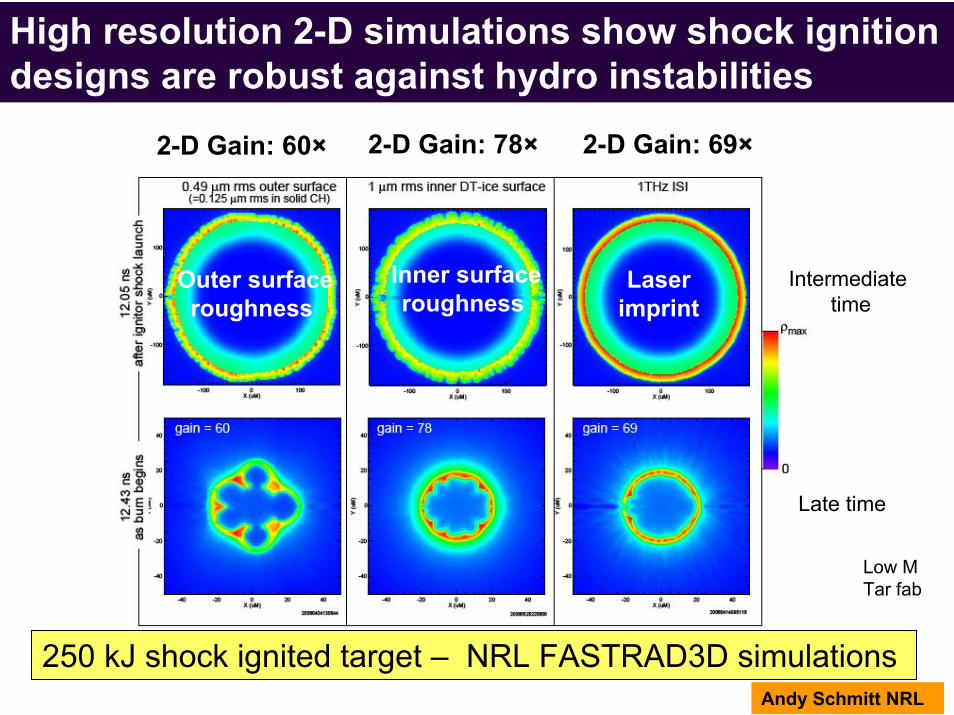
High resolution 2-D simulations show shock ignition designs are robust against hydro instabilities
250 kJ shock ignited target – NRL FASTRAD3D simulations
Outer surfaceroughness
Inner surfaceroughness
Laser imprint
Intermediatetime
Late time
Low MTar fab
2-D Gain: 60× 2-D Gain: 78× 2-D Gain: 69×
Andy Schmitt NRL

13
Target physics codes have been benchmarked with experiments on Nike Laser
Mass variation (mg/cm3)
time (ns)
Computer Model
CryogenicLiquid D2rippled targets

14
Laser driven instabilities cause problems:Produces high energy electrons that preheat DT fuelScatters laser beam, reducing drive efficiency
Expanding Plasma
X-rays
Plasmawaves
One challenge, in any laser target design ---Predicting Laser Plasma Instabilities (LPI)
Laser
electrons
DT Fuel
15
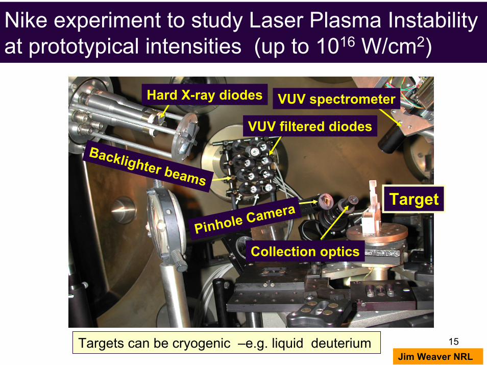
Target
Collection optics
Targets can be cryogenic –e.g. liquid deuterium
Nike experiment to study Laser Plasma Instability at prototypical intensities (up to 1016 W/cm2)
VUV filtered diodes
VUV spectrometerHard X-ray diodes
Pinhole Camera
Jim Weaver NRL
Backlighter beams
16
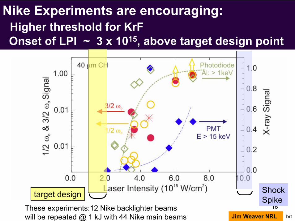
Nike Experiments are encouraging:Higher threshold for KrFOnset of LPI ~ 3 x 10¹⁵, above target design point
These experiments:12 Nike backlighter beamswill be repeated @ 1 kJ with 44 Nike main beams
target design ShockSpike
Jim Weaver NRL brt

17
Ehot =150 keV
LLNL (LASNEX) simulations suggest hot electrons induced by spike may be a good thing
John Perkins LLNL
Fractional conversion to hot electrons
GAIN
Ehot =40 keV
Ehot =100 keV
80
60
40
20
0
Gain 60 target may be able to withstand hot electrons up to 100 keV
0 0.2 0.4 0.6 0.8 1.0

18
Advances and Achievements
• target design• KrF lasers• final optics• target fabrication and engagement• chamber
19
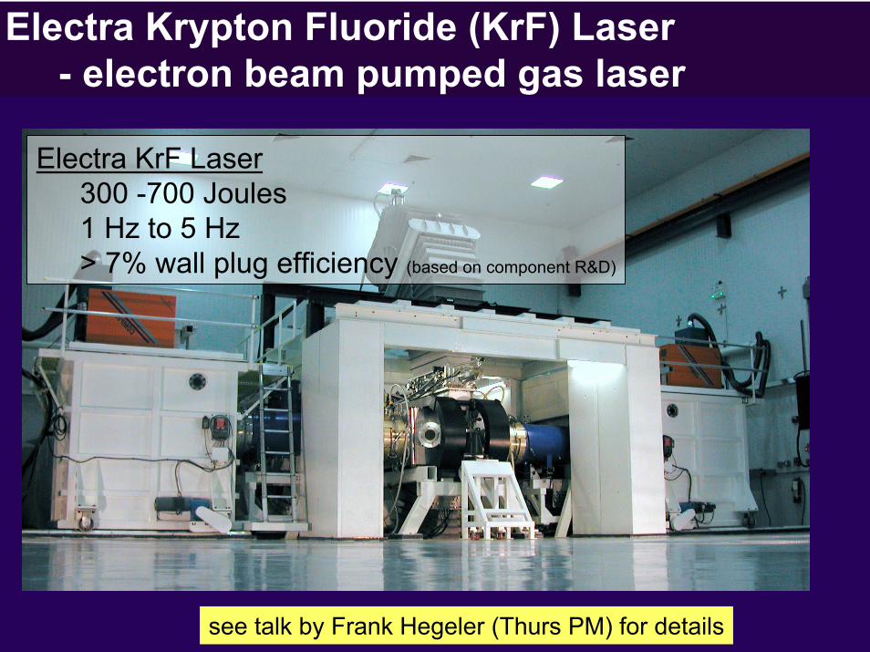
Electra Krypton Fluoride (KrF) Laser- electron beam pumped gas laser
Electra KrF Laser300 -700 Joules1 Hz to 5 Hz> 7% wall plug efficiency (based on component R&D)
see talk by Frank Hegeler (Thurs PM) for details

20
Advanced Solid State Pulsed Power Demo:1 M shots at 5 Hz, 400,000 shots @ 10 Hz
Based on Commercial switches (component life > 300 M shots)
> 80% efficiency
Attractive cost: < $ 2 M for Electra (15 kJ) Malcom McGeoch (PLEX)Steve Gldden (APP)
see talk by Frank Hegeler (Thurs PM) for details

21
Hibachi foil durability has been a challenge
Ribs(contain watercooling channels)
.001" thickStainless Steel Foil
This is a Hibachi Foil___was
Typical Foil lifetime: 5,000 - 15,000 shots

22
Plasma Physics to the rescue
Penning Ionization Gauge
Spectrometer tuned to look at Ar emission(>700 nm: below Ar, above everything else)
before
after
300 400 500 600 700 800 900 1000wavelength (nm)J Giuliani & R Jaynes (NRL)
23
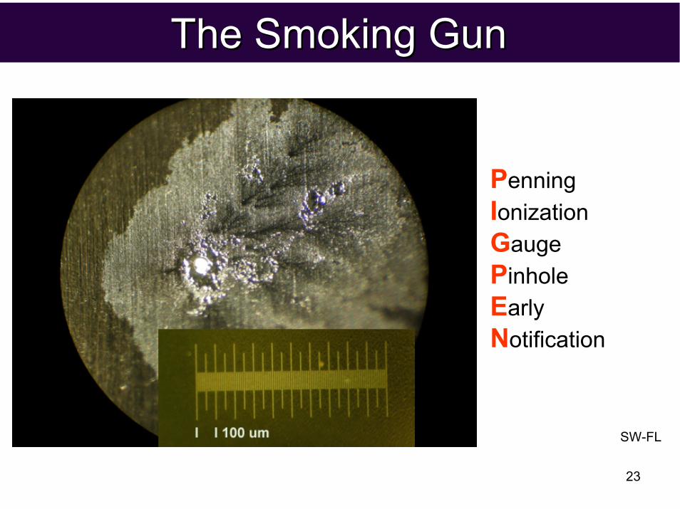
The Smoking GunThe Smoking Gun
PenningIonizationGaugePinholeEarlyNotification
SW-FL

24
Increasing A-K gap 10%, lowering charge volts 15%:Eliminated voltage reversal, and hence foil emission
RedA-K gap 5.3 cmCharge 43 kV
BlueA-K gap 5.9 cmCharge 36 kV
time (nsec)
300
200
100
0
-100
-200
-300
-400
-500
-6000 200 400 600 800 1200 1600
DiodeVoltage
(kV)

25
Electra continuous durability has been extended to the 90,000 shot range
Electra Cell after 30,000 shot continuous laser run
90,000 laser shots (10 hrs) continuous @ 2.5 Hz150,000 laser shots on same foils @ 2.5 Hz50,000 laser shots on same foils @ 5 Hz
300,000 laser shots in 8 days of operation500,000 e-beam shots since 12/31/2008
Most runs NOW limited by pulsed power

26
A video starring Electra

27
Advances and Achievements
• target design• lasers• final optics• target fabrication and engagement• chamber

28
The final optics train
Mohamed Sawan (Wisconsin)Malcolm McGeoch (PLEX)
M1.02 dpalifetime
M2.0003 dpalifetime
GIMM1.0 dpa2 year
CAD Drawing of Final Optics, Coupled with MCNP simulation of Neutron flux

29
GIMM laser damage threshold:> 3.5 J/cm2 @ 10 M shots
Mark Tillack (UCSD)
10 M shots at3.5 J/cm2
(not a limit!)

30
Wavelength (nm)
120
100
80
60
40
20
0R
efle
ctiv
ity (%
)200 220 240 260 280 300
Lance Snead (ORNL)Tom Lehecka (Penn State)Mohamed Sawan (Wisconsin)
Laser Damage Threshold(Al2O3/SiO2)
No dpa 0.001 dpa 0.01dpa 0.1 dpa
86-87% 84-86% 78-83% 83-84%
The "key":Match neutron-induced swelling in substrate and mirror layers
Experiment:Expose in HIFR (ORNL Reactor)Prototypical fluence, temperature
Measurements:ReflectivityLaser damage threshold
Dielectric mirror appears to resist predicted neutron fluence (0.02 dpa) on second mirror
Reflectivity(Al2O3/SiO2)

31
Advances and Achievements
• target design• lasers• final optics• target fabrication and engagement• chamber

32
Target fabrication:♦ Mass produce foam shells that meet specs♦ Fluidized bed for mass cryo layering♦ Estimate Cost < $0.16 each
100 mg/cc foam shell
W2
PC
Data
Laser A
Photodiode Sensors
Laser B
Variable Speed PumpTriple Orifice Generator
DAQInput/Output
Not to scale
W2
PC
Data
Laser A
Photodiode Sensors
Laser B
Variable Speed PumpTriple Orifice Generator
DAQInput/Output
Not to scale
Mass Production:22 shells/min
x-ray pictureof 4mm foam
GA, Schaffer, UCSD
Cryogenic Fluidized bed to make smooth DT ice

33
100%
75%
50%
25%
0%0 1 2 3 4 5 6 7 8
% NC
Spec1-3% NC
Recent target fabrication advances:♦ Higher yield in non-concentricity♦ Apply thin solid coat on foam during gellation
inner surface
5 μmSchaffer Corp
General Atomics
Proof of concept:Thin solid coating onDivinyl Benzine foam
Additional coating advances made at GA
Higher percentage of shells that meet non concentricity (NC) specs
Early DVB: 0%
RF foams: 10-15%
Advanced DVB foams 60%

34
Target Engagement:Concept based on detecting "Glint" off the target.
Target
Coincidence sensors
TargetInjector
TargetGlint
source
Dichroic mirrorCat’s eyeretroreflector
Wedged dichroicmirror
Grazingincidencemirror
Vacuum window
Focusingmirrors Drive
Laser
Align Laser
Amplifier / multiplexer/fast steering
mirrors
Glint off target
Lane Carlson (UCSD)

35
Target Engagement: Bench test: Mirror steers laser beam to target within 34 um. Need ∼20
Drop tower
Crossing sensors
Glint laser
Coincidence sensor
Poisson spot laser
Steering mirror
Driver beam
Drop tower
Crossing sensors
Glint laser
Coincidence sensor
Poisson spot laser
Steering mirror
Driver beam
Lane Carlson (UCSD)
34 μm RMS error

36
Advances and Achievements
• target design• lasers• final optics• target fabrication and engagement• chamber

37
x-rays
ionsneutrons
The "first wall" of the reaction chamber must withstand the steady pulses of x-rays, ions and neutrons from the target.
2%
73%
25%
first wall

38
Chamber optionsSolid wall/vacuum Simplest
Eases laser / target issuesMaterials challenge
Magnetic Intervention/vacuum Small chamberReally eases laser / target issuesThe ion dumps
Replaceable solid wall/vacuum Eases laser / target issuesMechanical/operational complexity
Gas in chamber Smaller chamberChallenging laser / target issuesClearing Chamber (plasma)
Thick liquid walls No materials issues (inc neutronics)Challenging laser / target issues Droplet formation/ complexity
Sawan, Wed SP3B-16
Gentile, Wed SP3B-21
combo
39
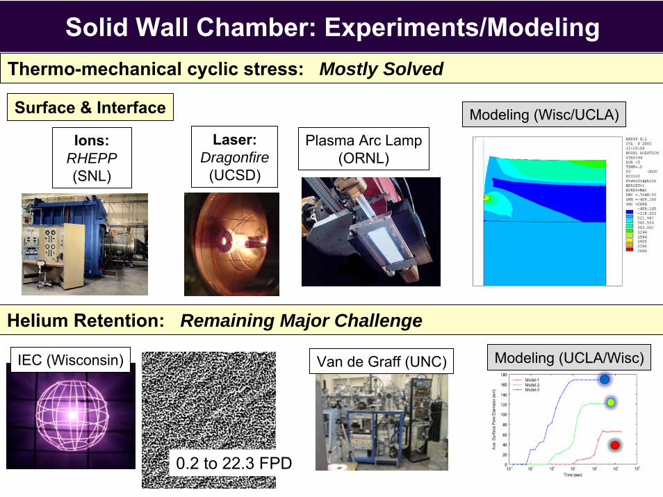
Solid Wall Chamber: Experiments/Modeling Thermo-mechanical cyclic stress: Mostly Solved
Helium Retention: Remaining Major Challenge
IEC (Wisconsin)
Laser: Dragonfire
(UCSD)
Van de Graff (UNC)
Ions:RHEPP(SNL)
0.2 to 22.3 FPD
Plasma Arc Lamp(ORNL)
Surface & Interface
Modeling (UCLA/Wisc)
Modeling (Wisc/UCLA)

40Sam Zenobia (Wisconsin)
First "Nano-Engineered" Tungsten helium retention experiments are encouraging
Exposure Time (equivalent FPD)0 50 100 150 200 250 300 350 400 450 500
Mass lossRate
(kg/FPD)
1.0
0.1
0.01
28 kg/FPY(< 1 um solid)
1019 10201018 Actual exposure (He+/cm2)(From 10 - 90 keV = approx 5% total spectrum)
1017
Mass loss rate:high at first,slows afterwards

41
Magnetic Intervention:Cusp magnetic field keeps ions off the wall(in Plasma Physics terms: Conservation of Pθ = rAθ = 0)
Axis Polar cusp (2)
Equatorialcusp
Plasma expansion initially spherical
Ion cloud deforms as it encounters cusp
Ions, at reduced power, leak into external dumps
1. Physics demonstrated in 1979 NRL experiment:R. E. Pechacek, et al., Phys. Rev. Lett. 45, 256 (1980).
2. NRL experiment modeled by D. Rose at Voss Scientific (2006)

42
Chamber radius: 5 mPoint cusps: 16 TMain coils: 0.75 T
Energy absorption in Ga:85% in first 10 mg/cm2
15% in next 100 mg/cm2
Only first layer evaporates
Gallium inventory enough so mean temp rise < 300°C
1 12 2
34 5
9
8
76
345
9
8
76
An example of a Magnetic Intervention Chamber Ions deflected downward by magnetic fieldsIon energy absorbed in Gallium Rain Ion Dissipaters™
ionorbits
beam tubes
chamber
coils
GalliumDroplets
NB Vapor P of Ga = 10-6T at 720 C
A.E. Robson, NRL (ret)

43
Objectives for next two years
•Nike: Experiments/theory show physics advantages of KrF.-- Refine/validate high gain designs
•Electra: Demonstrate >1 M shots continuous laser operation.-- with technologies capable of 300 M shots (e.g. all solid state)
•Develop critical IFE technologies. -- Mirrors, chamber concept(s), target fabrication / tracking, materials
If these are successful, next is a three stage program to IFE

44
A three stage plan for Laser Fusion Energy
500 kJ FTF
Single 5 Hz FTF beamline engages injected targets
Stage I : Develop full size components• Laser module (e.g. 18 kJ 5 Hz KrF beamline)• Target fabrication/injection/tracking• Chamber design• Refine basic pellet physics
Stage II Fusion Test Facility (FTF)• Demonstrate physics / technologies for a power plant• Develop/ validate fusion materials and structures• Operating: ~2022• Significant participation by private industry
Stage III Prototype Power plant(s)• Electricity to the grid• Transitioned to private industry 44

45
What makes a credible fusion energy program?
The only function of economic forecasting is to make astrology look respectable.
John Kenneth Galbraith
fusion

46
What have we accomplished? (1 of 2)or, the justification for pursuing an energy program
• KrF based target designs show energy class gains < 1 MJ.Designs backed with experimentally verified codesKrF advantages demonstrated (LPI, hydro, uniformity).
– Need experiments at higher energies, more robust designs
• KrF lasers demonstrated, with scalable technologies:Rep rate (2.5 - 5 Hz)Efficiency (> 7%) (with individual components)High energy rep-rate operation (250-700 J).Continuous operation (10 hr)Credible path to durability– Need integrated 1 M shot continuous demonstration
Continued on next slide....

47
What have we accomplished? (2 of 2)• Optics components resistant to prototypical neutrons, laser damage
– Need larger sizes, need extension to 300 M shots (from 10 M)
• Can mass produce high precision foam shells for targets– Need higher yield, Need gas tight coating
• Demonstrated smooth DT ice over foam layer– Need mass production layering demonstration (Fluidized bed)
• Demonstrated target engagement using glint technique– Need another 14 um pointing (now at 34, need 20)
• Several viable chamber concepts, backed with experiments/theory– Need refinement, integrated, economical design
• Have conceptual designs for ancillary components:– Blanket, tritium handling/processing, vacuum system, power conversion
48
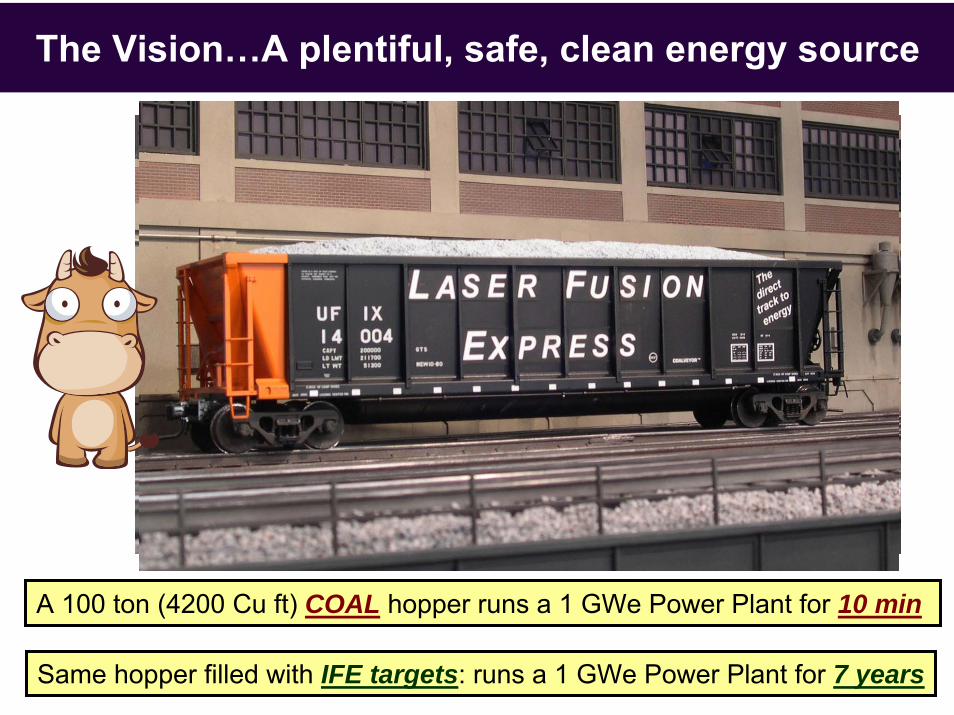
The Vision…A plentiful, safe, clean energy source
A 100 ton (4200 Cu ft) COAL hopper runs a 1 GWe Power Plant for 10 min
Same hopper filled with IFE targets: runs a 1 GWe Power Plant for 7 years

49
The Research Team
19th HAPL meetingOct 22-23, 2008
Madison WI 54 participants, 10 students
Universities1. UCSD2. Wisconsin3. Georgia Tech4. UCLA5. U Rochester, LLE6. UC Berkeley7. UNC8. Penn State Electro-optics
Government Labs1. NRL2. LLNL3. SNL4. LANL5. ORNL6. PPPL7. SRNL
Industry1. General Atomics2. L3/PSD3. Schafer Corp4. SAIC5. Commonwealth Tech6. Coherent7. Onyx8. DEI
9. Voss Scientific10. Northrup11. Ultramet, Inc12. Plasma Processes, Inc13. PLEX Corporation14. APP15. Research Scientific Inst16. Optiswitch Technology17. ESLI