Embed Size (px)
Citation preview

Refrigeration Scroll ZF09 K4...ZF18 K4ZS21 K4...ZS45 K4ZB15 KC...ZB45 KC
Application G
uidelines
AAPPPPLLIICCAATTIIOONN GGUUIIDDEELLIINNEESS:: CCOOPPEELLAANNDD SSCCRROOLLLL™™ CCOOMMPPRREESSSSOORRSS FFOORR RREEFFRRIIGGEERRAATTIIOONN:: ZZFF0099KK44--ZZFF1188KK44,, ZZSS2211KK44--ZZSS4455KK44,, ZZBB1155KKCC--ZZBB4455KKCC
1 Introduction ..........................................................................................................................................................2 2 Safety Instructions................................................................................................................................................2 3 Nomenclature.......................................................................................................................................................3 4 Model Designation ...............................................................................................................................................3 5 Qualified Refrigerants ..........................................................................................................................................3 6 Lubrication............................................................................................................................................................4 7 Refrigerant Injection.............................................................................................................................................4
7.1 Liquid Injection Details.........................................................................................................................................4 7.1.1 DTC Valve Specifications............................................................................................................................5 7.1.2 Valve Installation .........................................................................................................................................5 7.1.3 Compressor or Valve Service .....................................................................................................................5
8 Crankcase Heaters ..............................................................................................................................................6 9 Pump Down..........................................................................................................................................................6 10 Pressure Controls ................................................................................................................................................6
10.1 Internal Pressure Relief Valve.........................................................................................................................6 11 Discharge Temperature Protection......................................................................................................................7 12 Mufflers ................................................................................................................................................................7 13 Low Ambient cutout .............................................................................................................................................7 14 Shut Off................................................................................................................................................................7 15 Starting.................................................................................................................................................................7 16 Deep Vacuum Operation .....................................................................................................................................7 17 Brief Power Interruptions .....................................................................................................................................8 18 Standard Motor Protection...................................................................................................................................8 19 Electrical Installation ............................................................................................................................................8 20 SinglePhase Models ............................................................................................................................................8 21 ThreePhase Models.............................................................................................................................................8 22 Cable Connectors ................................................................................................................................................9 23 Compressor Functional Check ............................................................................................................................9 24 High Potential Testing........................................................................................................................................10 25 Installation..........................................................................................................................................................10 26 Shut off Valves and Adapters ............................................................................................................................11 27 Shell Temperature .............................................................................................................................................11 28 System Evacuation and Charging Procedure....................................................................................................11 29 Unbrazing System Components ........................................................................................................................12 30 Compressor Replacement .................................................................................................................................12 31 Suction Line Noise and Vibration.......................................................................................................................13 32 Application Envelopes .......................................................................................................................................14
32.1 R404a Application Envelopes .......................................................................................................................14 32.2 R22 Envelopes ..............................................................................................................................................15
C6.2.4/0603_0904/E 1

1 Introduction
The Copeland Scroll compressor has been under development at Copeland since 1979 and is the most efficient and durable compressor Copeland has ever developed for air conditioning, refrigeration and heat pump applications. It offers very low vibration and sound levels and is tolerant to stresses caused by liquid slugging, flooded starts, and debris commonly found in refrigeration systems. Available product range in this family is from 2.0 to 6 hp. For detailed information, please, refer to the Copeland Selection Software accessible free of charge from the Copeland Website at www.ecopeland.com or printed product selection catalgues. These guidelines are not meant to replace the system expertise available from system manufacturers.
2 Safety Instructions
Only qualified personnel should install and repair COPELAND compressors. • Refrigerant compressors must be employed only for the use they are made for. • Only approved refrigerant and refrigerating oils must be used. • Do not start the compressor until it is charged with refrigerant. • Correctly used, the compressor and the pressure line piping may reach temperatures that may
cause burning if touched.
• Wear safety goggles when working on open systems. • If the refrigerant needs to be removed from the system, do not disperse it in the environment, use
the correct equipment & method of removal. • For storage, use original packaging and avoid collisions and tilting.
• Trained electrical personnel must connect the compressor and its accessories. • All valid standards for connecting electrical and refrigeration equipment must be observed. • Limit values for the supply voltage of the unit may not be exceeded.
• It is not allowed to run a test without the compressor being connected to the system and without
refrigerant. It is of vital importance that the discharge stop valve has been fully opened before the compressor is started. If the discharge stop valve is closed or partly closed an unacceptable pressure with accordingly high temperatures may develop. When operating with air the so-called diesel effect may occur, i.e. the air sucked in is mixed with oil gas and can explode due to the high temperatures, and thereby destroy the compressor.
C6.2.4/0603_0904/E 2

3 Nomenclature
The model numbers of Copeland Scroll™ compressors have been designed to include a coded nominal capacity at ARI operating conditions in BTU/h at 60 Hz. All refrigeration scroll compressors are charged with Ester oil, which is indicated by the letter “E”.
4 Model Designation
Z S 3 0 K 4 E - T F D 5 5 1 1 2 3 4 5 6 7 1 Z = Scroll compressor family 2 S = High / medium temperature
F = Low temperature B = High / medium temperature
3 nominal capacity [BTU/h] @ 60 Hz and ARI conditions using multipliers "K" for 1000 and "M" for 10 000 4 model variation 5 POE oil 6 motor version 7 bill of material number
5 Qualified Refrigerants
R404A, R507, R22 and R134a are qualified for all refrigeration scroll compressors. The ZB compressor family is also qualified for R407C. It is essential that the glide of R 407C refrigerant blends be given careful consideration when adjusting pressure controls. The application envelopes for each refrigerant are shown in section 32.
C6.2.4/0603_0904/E 3

6 Lubrication
The oil level should be maintained at midpoint of the sight glass. If an oil regulator is being used the level should be set within the top half of the sight glass (for parallel operation please refer to guidelines C6.2.5/E). The compressor is supplied with an initial charge of polyolester (POE) lubricant. In the field the oil level could be topped up with Mobil EAL Arctic 22 CC. The recharge values can be taken from Copeland Selection Software. They must be operated with these specific oils only. Under no circumstances are ester oils to be mixed with mineral oil and/or alkyl benzene when used with chlorinefree refrigerants. Ester oil behaves extremely hygroscopically (see Figure 1), and this influences the chemical stability of the oil. The number of start/stop cycles should be limited to 10 per hour. A high cycling rate will pump oil into the system and may lead to lubrication failure. Oil leaves the compressor at start up regardless of the low oil carry over of the Scroll. The short running time is insufficient to return the oil to the compressor and possibly results in a lack of lubricant. It must be considered that the entire system will be coated with oil to some extent. Oil viscosity changes with temperature. System gas velocity changes depending on temperature and load. In low load conditions gas velocity may not be high enough to return oil to the compressor. System piping should be designed to return oil under all operating conditions, including part loads.
ppm�
1500�
1000�
500�
50� 100� 150� 250�200� 300�h
mineral oil
K11
.0/0
593�
POE
Figure 1 Absorption of moisture in ester oil in comparison to mineral oil in (PPM) byweight at 25°C and 50% relative humidity. h = hours
The system should be evacuated down to 0.3 mbar/ 0.22 Torr or lower. If there is uncertainty, as to the moisture content in the system, an oil sample should be taken from various points and tested for moisture. The residual moisture in the installation should be brought below 50 PPM by good evacuation practice and the use of a suitable filter drier with an equilibrium point dryness of 50PPM or less, according to ARI1710-86 or DIN 8948 (please refer to section 26 system evacuation and charging procedure) Sight glass/moisture indicators currently available can be used with the HFC refrigerants and lubricants; however, the moisture indicator will just show the moisture contents of the refrigerant. The actual moisture level of POE would be higher than the sight glass specifies. This is a result of the high hygroscopicity of the POE oil. As POE oil is very hygroscopic, it is recommended that the plugs in the compressor line connections be left in place until the compressor is set into position.
7 Refrigerant Injection
For low temperature ZF models, liquid injection is required to keep discharge gas temperatures within safe limits. The compressor is supplied with a 13/16" UNF diameter injection stub to accept a discharge temperature control (DTC) valve for liquid injection. Inside the compressor, injection takes place in two distinct pockets of the spirals without influencing the suction process. Injection increases the mass flow through the system slightly.
7.1 Liquid Injection Details Liquid injection is achieved by utilisation of a Discharge Temperature Control Valve (DTC) valve. The DTC valve eliminates the need for capillary tube, liquid injection solenoid valve and current relay, previously supplied with the ZF compressors (BOM 551) The same DTC valve can be used for all compressors and approved refrigerants. The ZF compressors (BOM 556) include a well in the top cap, combined with a valve cap. The Copeland DTC valve is equipped with a custom bulb profile, which must be installed in the top cap of the compressor, sensing the temperature closest to the discharge port. The bulb/bellows combination injects only when cooling is needed and in the required amounts. The connection to the liquid line is a 3/8" braze.
C6.2.4/0603_0904/E 4

7.1.1 DTC Valve Specifications Set Point: 89.4°C ± 2.4°C (193°F ± 5°F) Liquid Line Connection: 3/8"
7.1.2 Valve Installation The valve bulb must be installed in the top cap thermal well to adequately control scroll temperatures. The valve should be tightened on the injection fitting to a torque of 24-27 Nm (216-245 in. lbs.) It is reccommended the valve is located perpendicular to the compressor orientation however it will function properly in any orientation. The capillary tube connecting the valve to the bulb should be positioned at least 13 mm away from the side of the scroll to avoid contact during operation. The DTC Valve is supplied with an insulating cap which is applied to the top of the compressor, the valve cap could be replaced with thermal grease. This grease should be applied (minimum of 6 mm thick) to insulate and protect the valve. It is recommended to spread a thin film of thermal grease around the DTC Valve bulb before installing into the top cap well. We also recommend that a shut off valve in the liquid line is installed before the DTC valve, for ease of service.
7.1.3 Compressor or Valve Service Replacing a ZF compressor using the DTC Valve: We recommend replacing both the DTC Valve and the compressor at the same time. If you wish to use the existing DTC Valve, the valve filter should be cleaned and/or replaced. Replacing a capillary tube on a ZF compressor: The DTC Valve is not backward compatible on compressors with no thermal well in the top cap.
After Assembly
Check Assembly
5 Copper Tube Coil springBefore Assembly
2: DTC Valve
1: Coil Spring
3: DTC Bulb
4: Thermo Cap
Figure 2 DTC valve assembly
Assembly Procedure
1 Verify Coil Spring is seated in the “Groove” located in the well on top of the compressor.
2 Thread the Discharge Temperature ( DTC) valve onto the injection stub on the side of the compressor.
The Torque setting should be 24-27N/M (216-240 in/Lbs)
3 Press the DTC bulb into the well on top of the compressor until the DTC bottoms out in the well.
4 Snap the Thermo. cap onto the DTC bulb on top of the compressor
5 The copper tube from the DTC bulb should be approximately 0.125mm (1/8”) from the top of the compressor
C6.2.4/0603_0904/E 5

8 Crankcase Heaters
.Z.4.18.00
40
Equipment for heating the oil in the crankcase is necessary if the system configuration enables large amounts of refrigerant to condense in the compressor and be absorbed by the oil. At the high temperature produced by the heater
refrigerant is constantly vaporised and problems in oil supply are reduced. For correct mounting location of such a heater, please see Figure 3. The crankcase heater must be mounted below the oil removal valve located on the bottom shell. The crankcase heater must remain energised during compressor off cycles. The initial start in the field is a very critical period for any compressor because all load bearing surfaces are new and require a short break-in period to carry high loads under adverse conditions.
Figure 3 Crankcase Heater Location
Due to the Copeland Scroll’s inherent ability to handle liquid refrigerant in flooded conditions, no crankcase heater is required when the system charge does not exceed 4.5 kg. If a crankcase heater is fitted, it is recommended the heater must be turned on for a minimum of 12 hours prior to starting the compressor. This will prevent oil dilution and bearing stress on initial start up. Equipment for heating the oil in the crankcase is necessary if the system configuration enables large amounts of refrigerant to condense in the compressor and be absorbed by the oil. At the high temperature produced by the heater refrigerant is constantly vaporised and problems in oil supply are reduced. For correct mounting location of such a heater ple
9 Pum
To controscroll comexternal cIf the comcrankcasIf constanpump dow For ZB mthe unit fdifferentiaplenum o
10 Pres
Both high• Low P
ZF mZS an
• High The m
10.1 IntThere is differentiaaccordingonce the operation
C6.2.4/0603_
ase see Figure 3.
p Down
l refrigerant migration a pump down system could be used. The discharge check valve with refrigeration pressor is designed for low leak back and will allow the use of a pump down without the addition of an
heck valve. pressor is stationary for prolonged periods, refrigerant could migrate into the compressor and therefore a
e heater must be installed. t cold air is drawn over the compressor, this could make the crankcase heater ineffective, and therefore a n system is recommended.
odels, care should be taken because the scroll sets will unload at a pressure ratio of approximately 10:1. If ails to pump down, the pump down pressure should be reset to a higher value. The low pressure control l for all models needs to be reviewed since a relatively lower volume of gas will reexpand from the discharge
f the compressor into the low side on shut down.
sure Controls
and low pressure controls are required and the following working pressures are recommended: ressure
odels, the normal minimum setting should be 0.3 bar g (R404A), 0.0 bar g (R22). d ZB models, the LP cut out should be set as high as possible. The normal minimum is 2.6 bar g.
Pressure Switch aximum high pressure is 28 bar g.
ernal Pressure Relief Valve an internal pressure relief valve on all 2.0 to 6.0 hp refrigeration scroll compressors, which opens at a l pressure of 28 bar ± 3 bar between high and low pressure sides. A high pressure cut-out may be required to national regulations and is strongly recommended due to the capabilities of pumping to high pressures discharge is obstructed. The IPR valve is a safety device, not an HP switch. It is not designed for repeated and there is no guarantee it will re-set correctly if it does have repeated operation.
0904/E 6

11 Discharge Temperature Protection
Internal discharge temperatures reached under some extreme operating conditions (such as loss of refrigerant injection charge or extremely high compression ratio) could cause compressor damage. X
For this reason Copeland recommends THERMODISC thermostat 37TJ31 X 1976E. This thermostat has a cutout setting of 99 °C ± 4 K with 28 ± 5 K closing differential and should be installed approximately 120 mm from the discharge valve outlet (see Figure 4). In order to avoid improper functioning due to false readings this thermostat needs to be insulated (see “X” in Figure 4).
Figure 4 Recommended A discharge line thermostat is not required on ZB compressor models. For these odels, an internal thermodisc is positioned adjacent to the discharge port. When e thermodisc opens a small gas by pass occurs which trips the motor protector.
1
Fps
1
A
1
Svdt
1
DnNvslec
1
DF
C
position of discharge temperature protection
mth
The internal thermodisc opens at 146°C +/4°C and closes at 91°C +/7°C.2 Mufflers
low through Copeland Scroll compressors is continuous and has relatively low pulsations. External mufflers, reviously applied to piston compressors, may not be required for Copeland Scrolls. Because of variability between ystems, however, individual system tests should be performed to verify acceptability of sound performance.
3 Low Ambient cutout
low ambient cutout is not required to limit heat pump operation.
4 Shut Off
ince the Copeland Scroll compressor is also an excellent gas expander, the compressor may run backwards for a ery brief period at shutoff as the internal pressures equalise, and a typical sound is generated. A check valve in the ischarge connection of the compressor prevents the compressor from running backwards for more than a second or
wo. This momentary reversal of direction of the scrolls has no effect on compressor durability and is entirely normal.
5 Starting
uring the very brief startup, a short metallic sound is audible, resulting from initial contacting of the spirals and is ormal. o start assist devices are required for singlephase compressors, even if a system utilises nonbleed expansion alves. Due to the design of the Copeland Scroll, the internal compression components always start unloaded even if ystem pressures are not balanced. In addition, since internal compressor pressures are always balanced at startup, owvoltage starting characteristics are excellent for Copeland Scroll compressors. Moreover, if low voltage conditions xist at start up, protector trips could result. Start devices are available for single phase models to maximise starting haracteristics under abnormal conditions.
6 Deep Vacuum Operation
o not run a “refrigeration scroll” compressor in a deep vacuum. Failure to heed this advice can result in arcing of the usite pins causing permanent damage to the compressor.
6.2.4/0603_0904/E 7

17 Brief Power Interruptions
With single-phase refrigeration Copeland Scroll compressors, brief power interruptions of less than 1/2 second may result in powered reverse rotation. This occurs as a result of the highpressure discharge gas expanding backwards through the scrolls at power interruption, causing the scroll to orbit in the reverse direction. When power is reapplied while reverse rotation is occurring, the compressor may continue to run in the reverse direction for several minutes until the compressor’s internal protector trips. This has no effect on durability. When the protector resets the compressor will start and run normally. To avoid the loss of cooling resulting from powered reverse rotation Copeland strongly encourages the use of an electronic control which can sense brief power interruptions and will lock the compressor out of operation for approximately two minutes, or until the compressor has stopped rotating in reverse. This control could be
ther system controls (such as defrost or thermostat), or be a standalone control. Functional ntrol are the following: l cycle (0,02 sec at 50Hz operation) after power is removed and closes: 2 minutes (± 20 %)
has stopped rotating in reverse) whether power is restored or not.
incorporated with the ospecifications for this coTimer opens: 1 electrica(or until the compressor
18 Standard Motor Protection
Conventional inherent internal line break motor protection is provided with models ZF09K4….ZF18, ZS21K4*...ZS45K4, and ZB15KC….ZBS45KC
19 Electrical Installation
Independently from the internal motor protection, motor protection devices (fuses and circuit breakers) indicated by F6...8 have to be installed before the compressor as shown in figures 5 and 6. Selection of the circuit breakers, fuses have to be carried out according to VDE 0635 or DIN 57635 or IEC 2691 or EN602691. Motor insulation material class is “B” for models ZF09K4….ZF18, ZS21K4*...ZS45K4, and ZB15KC….ZBS45KC according to VDE 0530 or DIN 57530. The Fusite connections are marked as in figure 5. Recommended wiring diagrams are shown in figures 6 and 7. The screw terminals used on this compressor irrespective of applied voltage should be 2.5 to 2.6Nm.
20 SinglePhase Models
Single phase compressors (ZB Only) are connected to the common (C), start (S) and run (R) connections as usual. C
S
R
T1
T3
T2
E.2.09.00
Figure 5 Motor terminalconnections
21 ThreePhase Models
R
M1
CS
K1
F6��
F1
L1 N
L1NPE
Q1
�Control circuit��
C2
E.1.03.00
L1
M3
L2L3
K1
F6...8F1
L1 N
L1L2L3NPE
Q1
�Control circuit��
E.1.04.00
Figure 7 Power circuit threephaseFigure 6 Power circuit
single phase
Scroll compressors, like several other types of compressors, will only compress in one rotational direction. Direction of rotation is not an issue with singlephase compressors since they will always start and run in the proper direction. However, three phase compressors will rotate in either direction depending upon phasing of the power to L1, L2 and L3. Since there is a 50/50 chance of connecting power in such a way as to cause rotation in the reverse direction, it is important to include notices and instructions in appropriate locations on the equipment to ensure proper rotation direction is achieved when the system is installed and operated.
C6.2.4/0603_0904/E 8

Verification of proper rotation direction is made by observing that suction pressure drops and discharge pressure rises when the compressor is energised. Reverse rotation results in a sound level above that with correct rotation direction, as well as substantially reduced current draw compared to tabulated values and after several minutes of operation the compressor’s internal protector will trip. All three-phase compressors are wired identically internally. As a result, once the correct phasing is determined for a specific system or installation, connecting properly phased power leads to the same terminals should maintain proper rotation direction.
Model PFJ
TF5
TFC
TFD
ZF09/ZS21/ZB21 ZF11/ZS26/ZB26 ZF13/ZS30/ZB30 ZF15/ZS38/ZB38 ZF18/ZS45/ZB45
ZB19 ZB21 ZB26
- - - - - A A A
A A
B/C B/C B/C
- - - - -
A A
B/C B/C B/C
C Spade B Ring tongueA Flag receptacle
Figure 8 Cable connectors
22 Cable Connectors
The above table lists recommended types of cable connectors to be used for the various electric terminals of the compressors. “A” and “B” must fit 1/4" or 6.3 mm tab sizes. “C” are to be selected for #10 studs or diameters of 5mm respectively. Cable sizes are to be selected according to DIN ISO 0100, IEC 364 or national regulations.
23 Compressor Functional Check
No scroll compressor should be started with the suction service valve closed to check how low the compressor will pull suction pressure. This type of test may actually damage a refrigeration Scroll compressor, rather, the following diagnostic procedure should be used to evaluate whether the Scroll compressor is functioning properly. • Proper voltage to the unit should be verified. • Normal motor winding continuity and short to ground checks will determine if the inherent overload motor
protector has opened or if an internal short to ground has developed. If the protector has opened, the compressor must cool sufficiently to reset.
• With service gauges connected to suction and discharge pressure fittings, turn on the compressor. If the suction pressure falls below normal levels the system is either low on charge or there is a flow blockage in the system.
• Single Phase compressors If suction pressure does not drop and discharge pressure does not rise to normal levels, either the reversing valve or the compressor is faulty. Use normal diagnostic procedures to check operation of the reversing valve. • Three Phase Compressor If suction pressure does not drop and discharge pressure does not rise to normal levels, reverse any two of the compressor power leads and reapply power to make sure compressor was not wired to run in reverse direction. If pressures still do not move to normal values, the compressor is faulty. If the compressor is in a circuit containing a reversing valve, this item may be faulty Reconnect the compressor leads as originally configured and use normal diagnostic procedures to check operation of the reversing valve. If the reversing valve checks out satisfactorily, then the compressor current draw should be compared to published compressor performance data at the compressor operating conditions (pressures and voltages) and significant deviations (more than ±15%) from published values may indicate a faulty compressor.
C6.2.4/0603_0904/E 9
24 High Potential Testing
Copeland subjects all scroll compressors to a high voltage test after final assembly. Since high voltage tests lead to premature ageing of the winding insulation we do not recommend additional tests of that nature. They may also be carried out with new machines only. If it has to be done for any reason disconnect all electronic devices (e.g. motor protection module, fan speed control, etc.) prior to testing. The test voltage of 1000 V plus twice the nominal voltage is applied for 1 4 seconds between motor winding (each one of the phases) and the compressor shell: The maximum leak current limit is approximately 10 mA. Repeated tests have to be performed at lower voltages. Caution: Do not carry out high voltage or insulation tests if the compressor housing is under vacuum. Copeland Scroll compressors are configured with the motor down and the pumping components at the top of the shell. As a result, the motor can be immersed in refrigerant to a greater extent than hermetic reciprocating compressors when liquid refrigerant is present in the shell. In this respect, the scroll is more like semihermetics (which have horizontal motors partially submerged in oil and refrigerant). When Copeland Scroll compressors are high potential tested with liquid refrigerant in the shell they can show higher levels of leakage current than compressors with the motor on top because of the higher electrical conductivity of liquid refrigerant than refrigerant vapour and oil. However, this phenomenon can occur with any compressor when the motor is immersed in refrigerant. The levels of current leakage do not present any safety issue. To lower the current leakage reading the system should be operated for a brief period of time to redistribute the refrigerant to a more normal configuration and the system high potential tested again.
25 Installation
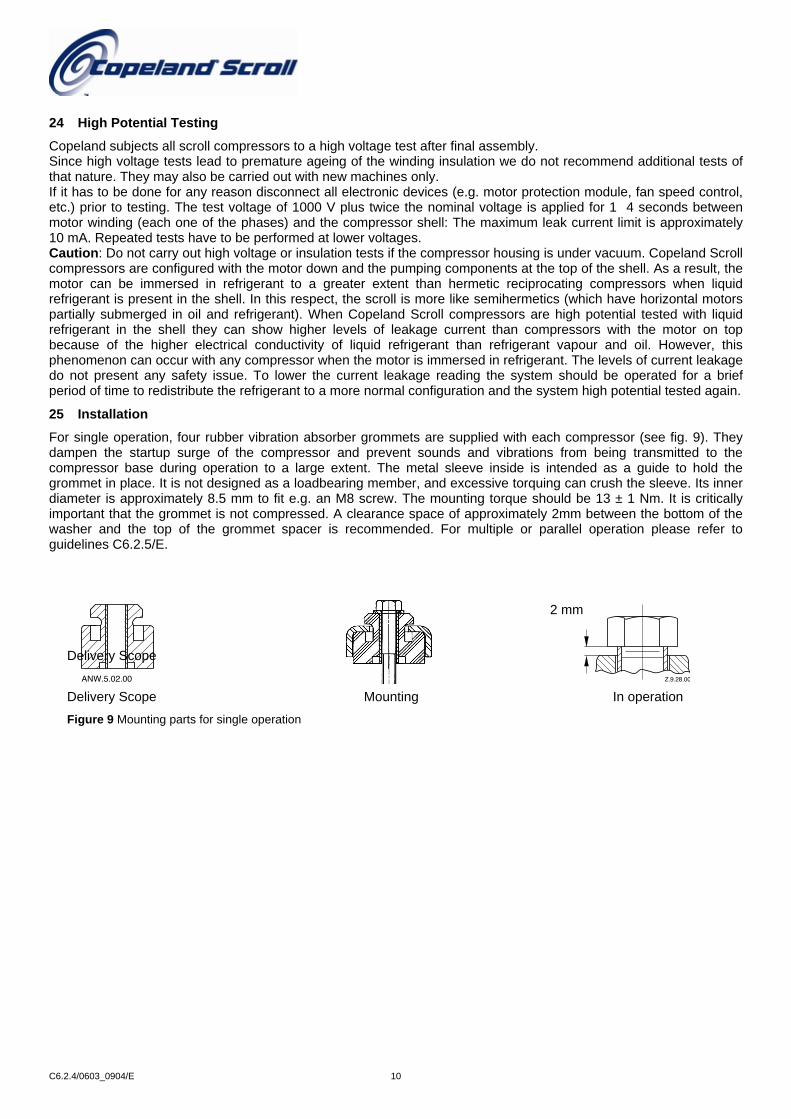
For single operation, four rubber vibration absorber grommets are supplied with each compressor (see fig. 9). They dampen the startup surge of the compressor and prevent sounds and vibrations from being transmitted to the compressor base during operation to a large extent. The metal sleeve inside is intended as a guide to hold the grommet in place. It is not designed as a loadbearing member, and excessive torquing can crush the sleeve. Its inner diameter is approximately 8.5 mm to fit e.g. an M8 screw. The mounting torque should be 13 ± 1 Nm. It is critically
met is not compressed. A clearance space of approximately 2mm between the bottom of the
important that the grom washer and the top of the grommet spacer is recommended. For multiple or parallel operation please refer to guidelines C6.2.5/E.Delivery Scope ANW.5.02.00 Z.9.28.00
Figure 9 Mounting parts for single operation
2 mm
In operationMountingDelivery Scope
C6.2.4/0603_0904/E 10

26 Shut off Valves and Adapters
The refrigeration scroll compressors are delivered with threads for Rotalock shut off alves. Brazed pipework can also fit compressors with Rotalock connections using adapters “A” and “B” in either straight or angled “C”. It is strongly recommended to periodically re-torque all fixing connections to the original setting after the system has been put into operation. (See Fig 10 and spare parts list ZF/ZS and ZB)
a
c
b
(1) (2)
Z.8.07.00
c
b
a
d
Z.8.09.00Z.8.10.00
BB AA c
ba
Z.8.08.00
CC
Torque [Nm]Rotalock 3/4"-16UNF 40 - 50 Rotalock 1"-14UNS 70-80
Rotalock 1"1/4-12UNF 120-135 Rotalock 1"3/4-12UNF 135-160 Rotalock 2"1/4-12UNF 165-190
Sight Glass 25-25.5 Figure 10 Shut off valves and adaptors
27 Shell Temperature
Under rare circumstances caused by failure of system components such as the condenser or evaporator fan, or loss of charge, and depending on the type of expansion control, the top shell and discharge line can briefly but repeatedly reach temperatures above 177°C as the compressor cycles on its internal protection devices. Care must be taken to ensure that wiring or other materials, which could be damaged by these temperatures, do not come into contact with the shell.
28 System Evacuation and Charging Procedure
Before the installation is put into commission, it has to be evacuated with a vacuum pump. During the initial procedure, suction and discharge shutoff valves on the compressor remain closed. The installation of adequately sized access valves at the furthest point from the compressor in the suction and liquid line is advisable. Pressure must be measured using a vacuum pressure (Torr) gauge on the access valves and not on the vacuum pump; this serves to avoid incorrect measurements resulting from the pressure gradient along the connecting lines to the pump. These valves could also be used to measure the operating pressures to ensure there are no excessive pressure drops in the suction line and liquid line, which will also give an indication that the expansion device receives full bore liquid, ensuring the system performs at its most efficiently. Evacuating the system only on the suction side of a Scroll compressor can occasionally result in a temporary nostart condition for the compressor. The reason for this is that the floating seal could axially seal with the scroll set, with the higher pressure on the floating seal. Consequently, until the pressures equalize, the floating seal and scroll set can be held tightly together.
C6.2.4/0603_0904/E 11

The installation should be evacuated down to 0.3 mbar/ 0.22 Torr or lower. Subsequently, the factory holding charge of dry air in the compressor is released to the ambient, The shutoff valves are opened and the installation, including the compressor, are once more evacuated as described after the system has been recharged with dry nitrogen. Highest demands are placed on the leak proof design of the installation and also on the leak testing methods. (Please refer to EN378). Rapid charging on the suction side of Scroll compressors can occasionally result in a temporary nostart condition for the compressor. The reason for this is that if the flanks of the spirals happen to be in a sealed position, rapid pressurization of the low side without opposing high side pressure can cause the spirals to seal axially. Consequently, until the pressures eventually equalize, the spirals can be held tightly together, preventing rotation. The best way to avoid this situation is to charge on both the high and low side simultaneously at a rate, which does not result in axial loading of the spirals. The maximum charging rate can be determined through simple tests.
29 Unbrazing System Components
If the refrigerant charge is removed from a scroll equipped unit by bleeding the high side only, it is sometimes possible for the scrolls to seal, preventing pressure equalization through the compressor. This may leave the low side shell and suction line tubing pressurized. If a brazing torch is then applied to the low side while the low side shell and suction line contains pressure, the pressurized refrigerant and oil mixture could ignite when it escapes and contacts the brazing flame. To prevent this occurrence, it is important to check both the high and low side with gauges before unbrazing, or in the case of repairing a unit on an assembly line, bleed refrigerant from both the high and low side. Instructions should be provided in appropriate product literature and assembly (line repair) areas.
30 Compressor Replacement
In the case of a motor burn, the majority of contaminated oil will be removed with the compressor. The rest of the oil is cleaned through use of suction and liquid line filter dryers. A 100% activated alumina suction filter drier is recommended but must be removed after 72 hours. It is highly recommended that the suction accumulator be replaced if the system contains one. This is because the accumulator oil return orifice or screen may be plugged with debris or may become plugged shortly after a compressor failure. This will result in starvation of oil to the replacement compressor and a second failure. When a single compressor or tandem is exchanged in the field, a major portion of the oil may still be in the system. While this may not affect the reliability of the replacement compressor, the extra oil will add to rotor drag and increase power usage. See Section 27 for Rotalock valve, flange fittings, sight glass, and mounting bolt torques values.
C6.2.4/0603_0904/E 12
31 Suction Line Noise and Vibration
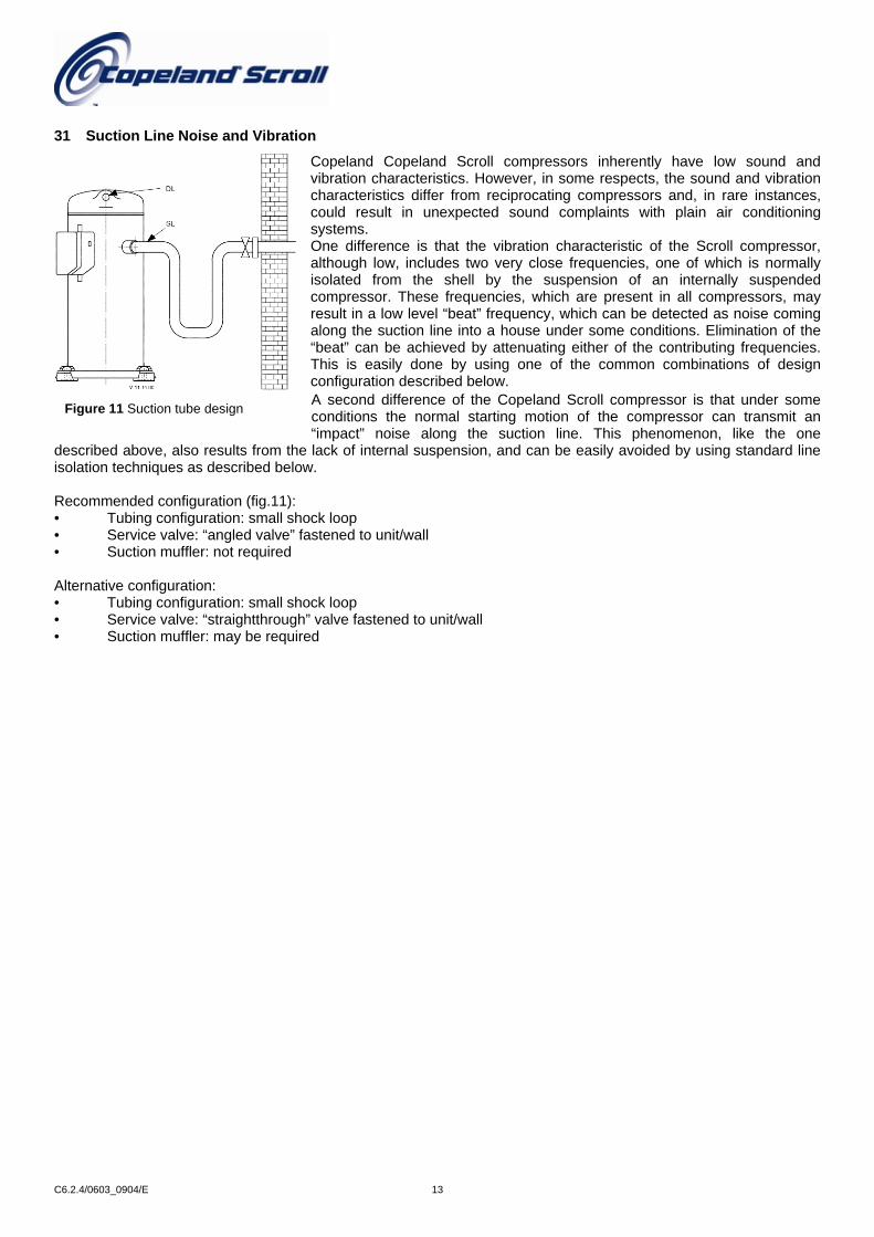
Copeland Copeland Scroll compressors inherently have low sound and vibration characteristics. However, in some respects, the sound and vibration characteristics differ from reciprocating compressors and, in rare instances, could result in unexpected sound complaints with plain air conditioning systems. One difference is that the vibration characteristic of the Scroll compressor, although low, includes two very close frequencies, one of which is normally isolated from the shell by the suspension of an internally suspended compressor. These frequencies, which are present in all compressors, may result in a low level “beat” frequency, which can be detected as noise coming along the suction line into a house under some conditions. Elimination of the “beat” can be achieved by attenuating either of the contributing frequencies. This is easily done by using one of the common combinations of design configuration described below. A second difference of the Copeland Scroll compressor is that under some conditions the normal starting motion of the compressor can transmit an “impact” noise along the suction line. This phenomenon, like the one
described above, also results from the lack of internal suspension, and can be easily avoided by using standard line isolation techniques as described below.
Figure 11 Suction tube design
Recommended configuration (fig.11): • Tubing configuration: small shock loop • Service valve: “angled valve” fastened to unit/wall • Suction muffler: not required Alternative configuration: • Tubing configuration: small shock loop • Service valve: “straightthrough” valve fastened to unit/wall • Suction muffler: may be required
C6.2.4/0603_0904/E 13

32 Application Envelopes
32.1 R404a Application Envelopes
Tc °
C
Te °C
ZF09K4E to ZF18K4E Tc
°C
Te °C
ZS21K4 to ZS45K4
/E 14
Tc°C
Te °C
ZB15KC to ZB45KC
C6.2.4/0603_0904

32.2 R22 Envelopes
Tc°C
Te °C
ZF09K4 to ZF18K4
Te °C
Te °C
Tc°C
ZS21K4 to ZS45K4
Tc°C
C
C6.2.4/0603_0904/E
ZB15KC to ZB45K
Te °C
15

Notes

C6.
2.4
/ 060
3-09
04/E
Copeland Marketing & Sales - 27, Rue des Trois Bourdons - B 4840 Welkenraedt, Belgium
Tel. +32 (0) 87 305411 - Fax +32 (0) 87 305506 - internet: www.ecopeland.com - email: [email protected]
The Emerson logo is a trademark and service mark of Emerson Electric Co. Copeland Corporation is a division of Emerson Electric Co. Copeland is a registered trademark and Copeland Scroll is a trademark of Copeland Corporation. All other trademarks are the property of their respective owners. Information contained in this brochure is subject to change without notification.
© 2004 Copeland
Benelux Eastern Europe, Turkey & IranDeltakade 7 27, Rue des Trois BourdonsNL-5928 PX Venlo B-4840 WelkenraedtTel. +31 (0) 77 324 0234 Tel. +32 (0) 87 305 061Fax +31 (0) 77 324 0235 Fax +32 (0) 87 305 506
Deutschland/Österreich & Schweiz PolandSenefelder Straße 3 11A, KonstruktorskaD-63477 Maintal P-02-673 WarszawaTel. +49 (0)6109 6059 0 Tel. +48 225 458 9205Fax +49 (0)6109 6059 40 Fax +48 225 458 9255
France/Greece & Maghreb Russia & CIS8, Allee Du Moulin Berger Malaya Trubetskaya, 8-11th FloorF-69130 Ecully RUS-119881 MoscowTel. +33 (0)4 78668570 Tel. +7 095 232 94 72Fax +33 (0)4 78668571 Fax +7 095 232 03 56
Italia Middle East & AfricaVia Ramazzotti, 26 PO Box 26382, R/A 8, FD-2I-21047 Saronno (va) Jebel Ali, Dubai - UAETel. +39 02 961781 Tel. +9714 883 2828Fax +39 02 96178888 Fax +9714 883 2848
España & Portugal
Sweden/Denmark/Norway & Finland
Diputacion, 238 AT.8
Östbergavägen 4, P.O.Box 10
E-08007 Barcelona
S-59021 Väderstad
Tel. +34 93 4123752
Tel. +46 (0) 142 70520
Fax +34 93 4124215
Fax +46 (0) 142 70521
UK & IrelandColthrop WayGB- Thatcham, Berkshire - RG19 4 NQTel. +44 (0)1635 87 6161Fax +44 (0)1635 877111
Asia/Pacific10/F, Pioneer Building, 213 Wai Yip Street,Kwun Tong, Kowloon - Hong KongTel. +852 28 66 31 08Fax +852 25 20 62 27
Latin America7975 North West 154Th Street - Suite 300Miami Lakes, FL, 33016 - USATel. +1 305 818 8880Fax +1 305 818 8888