Embed Size (px)
Citation preview
REAL-Time CGM Sensor Start and Initiation
9402471-011

Objective
A step-by-step guide to starting a sensor using the MiniMed Paradigm® REAL-Time Continuous Glucose Monitoring System
Key Points• Review sensor start and how to program glucose sensor
settings• Review proper technique for sensor placement and
insertion • Review alarms and sensor troubleshooting
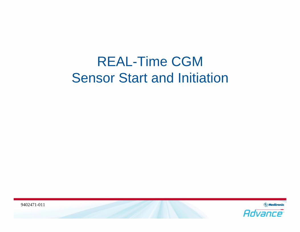
UP Button
DOWN Button
ACT ButtonESC ButtonBOLUSButton
MiniMed Paradigm® Insulin Pump Home Screen
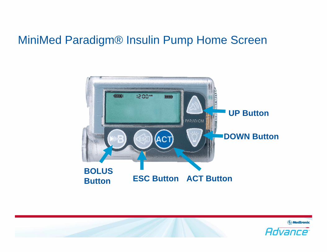
MiniMed Paradigm® Insulin Pump Home Screen
Alert/alarmIcon
Normal mode (no icon)The insulin pump is On and delivering insulin as programmed.
Special mode (open circle)Insulin pump is On - delivering insulin as programmed (with certain conditions, temp basal, square/dual wave bolus, low reservoir, low battery, etc.).
Attention mode (closed circle)Insulin pump is NOT delivering insulin.
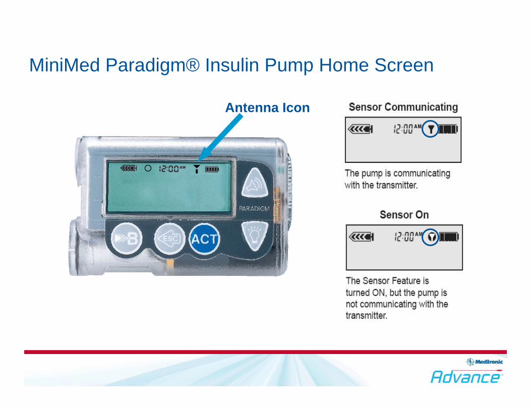
Antenna Icon
MiniMed Paradigm® Insulin Pump Home Screen

Press the ACT button to access the main menu
Accessing the Main Menu
Main Menu
Suspend
Sensor
Basal
Prime
Bolus
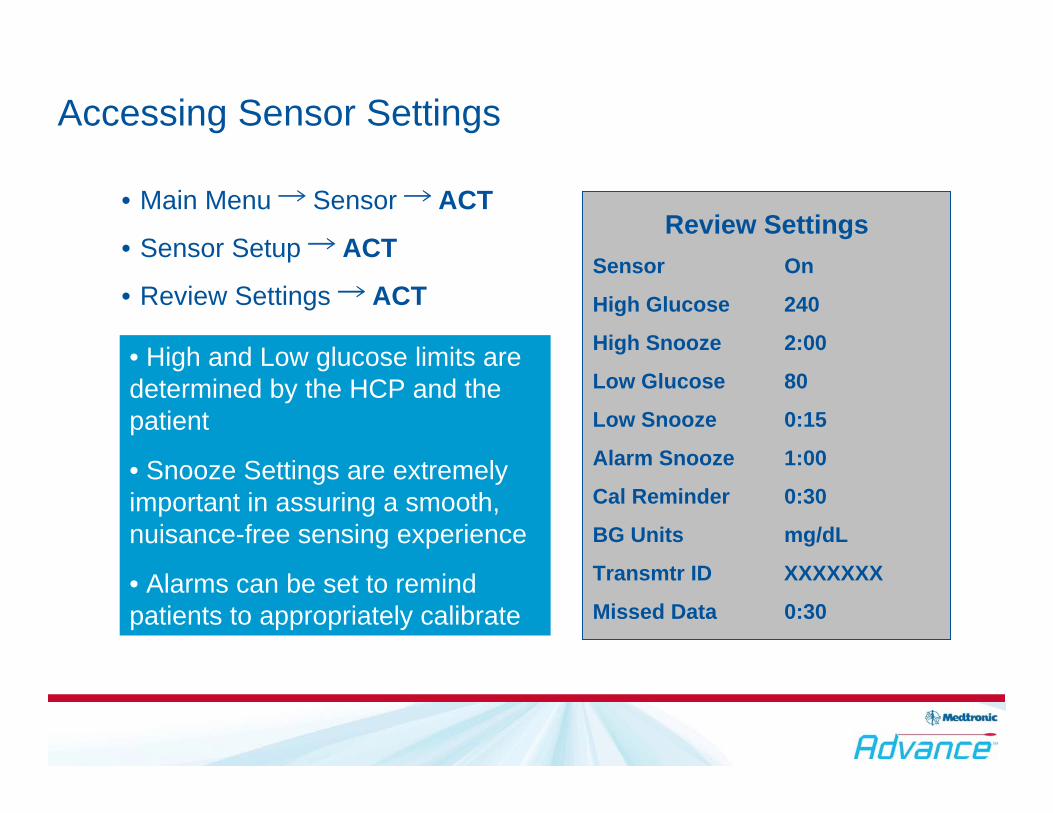
Accessing Sensor Settings
• Main Menu → Sensor → ACT
• Sensor Setup → ACT
• Review Settings → ACT
Review SettingsSensor On
High Glucose 240
High Snooze 2:00
Low Glucose 80
Low Snooze 0:15
Alarm Snooze 1:00
Cal Reminder 0:30
BG Units mg/dL
Transmtr ID XXXXXXX
Missed Data 0:30
Table Activity
• High and Low glucose limits are determined by the HCP and the patient
• Snooze Settings are extremely important in assuring a smooth, nuisance-free sensing experience
• Alarms can be set to remind patients to appropriately calibrate

Glucose Sensor Settings

60
• Ensure the Sensor is placed snugly into the SenSerter so that the o-rings are NOT visible
• The angle of Sensor insertion is crucial for appropriate Sensor penetration depth and “wetting”
• Insert the Sensor at a minimum of 60° by gently tilting the SenSerter forward
Sensor Insertion
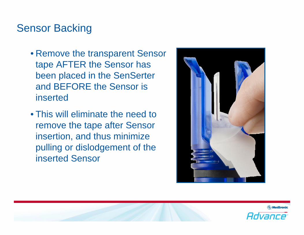
• Remove the transparent Sensor tape AFTER the Sensor has been placed in the SenSerter and BEFORE the Sensor is inserted
• This will eliminate the need to remove the tape after Sensor insertion, and thus minimize pulling or dislodgement of the inserted Sensor
Sensor Backing
Taut Skin• Hold the skin taut at the Sensor site. Do not pinch the skin
as doing so may prevent optimal Sensor penetration
Needle Removal• Hold the base of the Sensor firmly. Pull the needle out
smoothly in one motion and at the SAME ANGLE as inserted
• Do not ROCK the Sensor when pulling out the needle, as this may jeopardize Sensor penetration and may damage the Sensor electrodes
Bleeding• If bleeding occurs after Sensor insertion, apply gentle
pressure for 3 minutes
Placing the Sensor
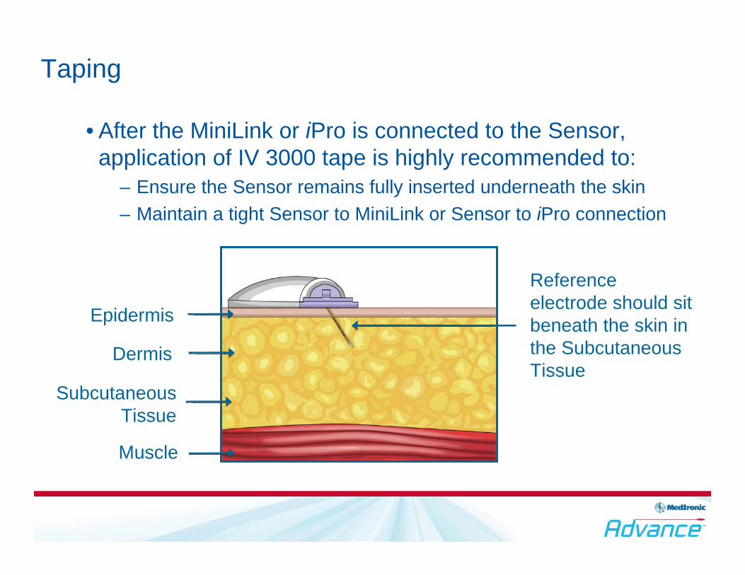
Epidermis
Dermis
Subcutaneous Tissue
Muscle
Reference electrode should sit beneath the skin inthe Subcutaneous Tissue
• After the MiniLink or iPro is connected to the Sensor, application of IV 3000 tape is highly recommended to:
– Ensure the Sensor remains fully inserted underneath the skin– Maintain a tight Sensor to MiniLink or Sensor to iPro connection
Taping
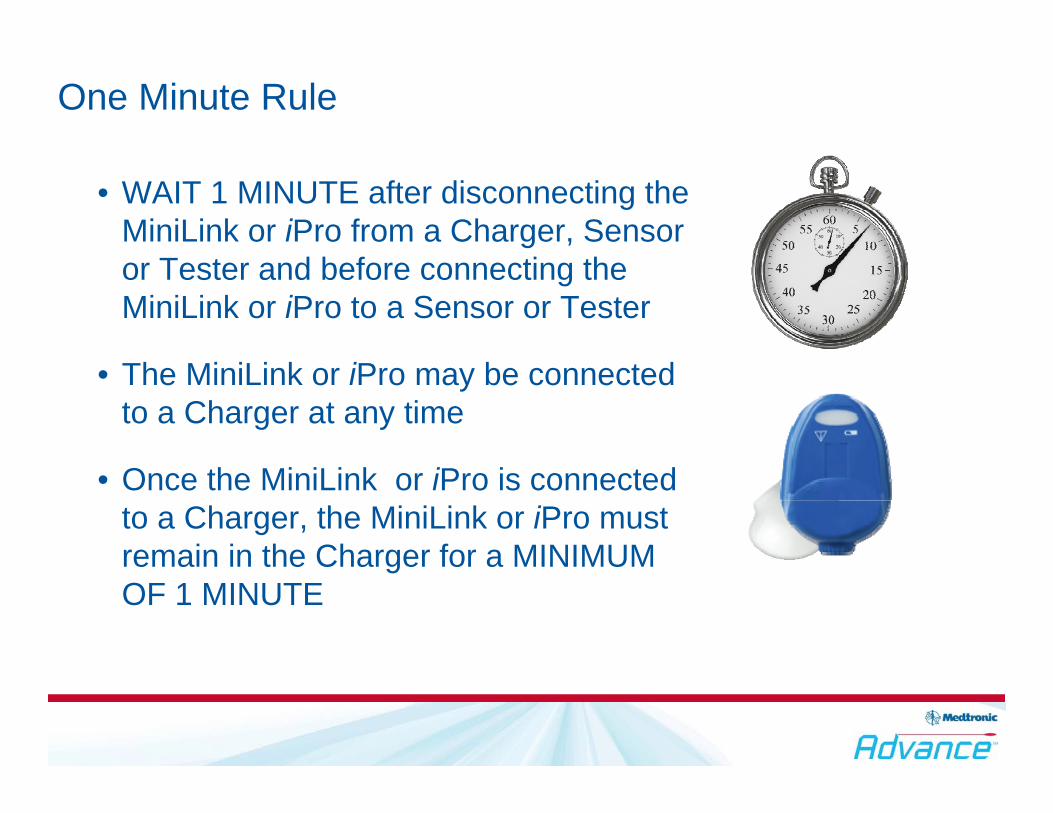
• WAIT 1 MINUTE after disconnecting the MiniLink or iPro from a Charger, Sensor or Tester and before connecting the MiniLink or iPro to a Sensor or Tester
• The MiniLink or iPro may be connected to a Charger at any time
• Once the MiniLink or iPro is connected to a Charger, the MiniLink or iPro must remain in the Charger for a MINIMUM OF 1 MINUTE
One Minute Rule

Instruct patients to diligently check for the flashing green light
• The MiniLink or iPro should flash green within 20 seconds AFTER it is connected to the Sensor
• The flashing green light signals:
– The Sensor is wet
– There is enough power to last for a 3-day Sensor use
MiniLink or iPro Flash

Calibration Tips
• After inserting a glucose sensor and performing a Glucose Sensor Start, a 2-hour warm-up period is required
• The glucose sensor must be calibrated with a meter BG, as prompted by an Enter Meter BG alarm
• On the first day of glucose sensor use, an additional BG reading must be entered within 6-hours after the initial calibration
• Thereafter, the glucose sensor must be calibrated a minimum of twice a day (every 12-hours)
• Calibrate at times when blood glucose (BG) is stable (fasting, premeal, bedtime)
• Avoid calibrations during times of rapid glucose change (post-meal, following a bolus, exercise)
• Calibrate before bedtime to avoid a METER BG NOW alarm during the night
• Use good technique when performing BG fingersticks for calibration
Optimal Calibration
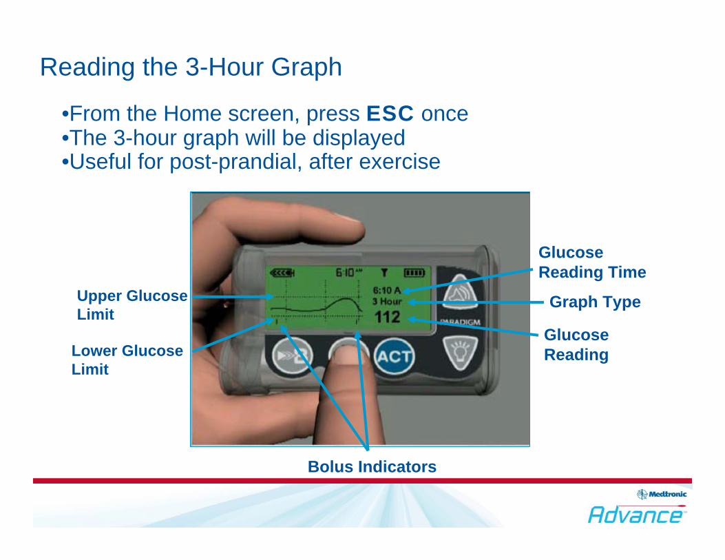
Reading the 3-Hour Graph
•From the Home screen, press ESC once•The 3-hour graph will be displayed•Useful for post-prandial, after exercise
Glucose Reading Time
Graph Type
Glucose Reading
Bolus Indicators
Lower Glucose Limit
Upper Glucose Limit
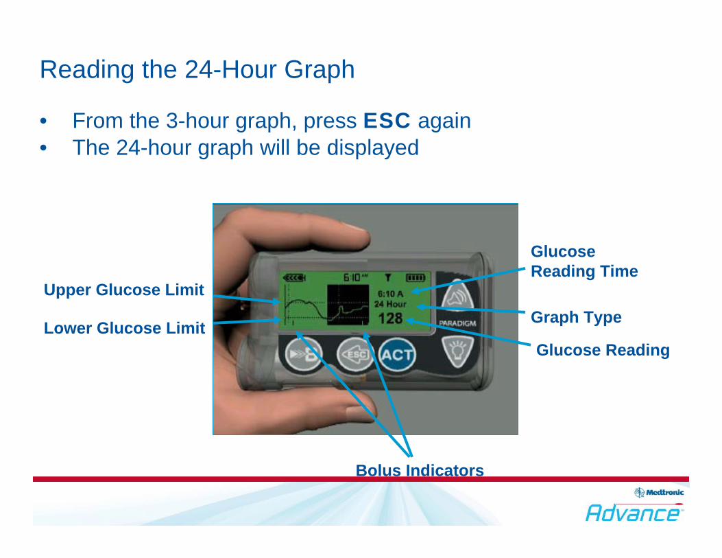
Reading the 24-Hour Graph
• From the 3-hour graph, press ESC again• The 24-hour graph will be displayed
GlucoseReading Time
Graph Type
Glucose Reading
Bolus Indicators
Lower Glucose Limit
Upper Glucose Limit

Alarm Troubleshooting
Meter BG Now: Enter a meter BG reading for calibration
Weak Signal: Change proximity/orientation of insulin pump to transmitter
Lost Sensor: Change proximity/orientation of pump to transmitter and go to Find Lost Sensor
Cal Error: Calibrate in glucose steady state; If Cal Erroroccurs, delay repeat calibration until glucose is no longer changing rapidly
Bad Sensor: 2 Cal errors in a row will result in “bad sensor”
Sensor Error: Out of range or unstable signal is detected by the transmitter. If this alarms occurs repeatedly, the user should change the sensor. If it is an isolated incident, no action is required

Medtronic Diabetes18000 Devonshire StreetNorthridge, CA 91325www.medtronicdiabetes.com 1-800-646-4633