Embed Size (px)
Citation preview

www.reinhausen.com
ON-LOAD TAP-CHANGER RMV-A 600 A / 1320 AOperating Instructions

© 2010 All rights reserved, Maschinenfabrik Reinhausen
Unauthorised copying and distribution of this document and the utilisation and communication of its contents
are strictly prohibited unless expressly authorised.
Offenders will be held liable for the payment of damages. All rights reserved in the case of registration of a patent, utility model or registered design.
The product may have been modified after this document went to press.
We expressly reserve the right to make changes to the technical data, the design or the scope of delivery.
The information provided and the arrangements agreed during processing of the relevant quotations and orders are strictly binding.
The original operating instructions were drawn up in German.

Content
© Maschinenfabrik Reinhausen 2010 2161246/00 EN VACUTAP® RMV-A 3
Content
1 Technical Data ............................................................................. 11
1.1 General Data........................................................................................... 11
1.2 Application Limits .................................................................................... 11
1.3 Equipment Standard Features ................................................................12
2 Safety instructions...................................................................... 13
3 Description .................................................................................. 15
3.1 Design .....................................................................................................16
3.2 Operation ................................................................................................18
3.3 Tap Selector ............................................................................................20
3.4 Change-over Selector (Reversing or Coarse/Fine).................................21
3.5 Vacuum Interrupter..................................................................................21
3.6 By-Pass Switch .......................................................................................22
3.7 Monitoring System ..................................................................................23
3.8 Drive Mechanism/Cam Switch Assembly................................................25
3.8.1 Option................................................................................................................. 26
4 Installation ................................................................................... 27
4.1 Receiving, Handling and Storage............................................................27
4.2 Mechanical Set-up ..................................................................................28
4.2.1 Attaching the Oil Compartment .......................................................................... 284.2.2 Mounting the Drive Mechanism Air Compartment.............................................. 28

Content
4 VACUTAP® RMV-A 2161246/00 EN © Maschinenfabrik Reinhausen 2010
4.3 Electrical Connections ............................................................................ 29
4.3.1 Connecting the Tap Leads to the LTC ................................................................ 294.3.2 Connecting the Monitoring System and the Drive Mechanism........................... 29
4.4 Test Procedures...................................................................................... 29
4.4.1 Manual Test Procedures..................................................................................... 294.4.2 Motorized Test Operations ................................................................................. 304.4.3 Monitoring System Tests .................................................................................... 31
4.5 Oil Filling/Transformer Vacuum Processing............................................ 34
5 Maintenance-Free Schedules and Service................................35
5.1 Maintenance-Free Intervals .................................................................... 35
5.2 Taking the LTC out of Service................................................................. 36
5.3 Draining the Oil ....................................................................................... 36
5.4 Internal Examination ............................................................................... 37
5.4.1 By-Pass Switch .................................................................................................. 385.4.2 Vacuum Interrupter Examination ........................................................................ 38
5.5 Preparing the LTC for Service ................................................................ 42
6 Replacement of the Vacuum Interrupter Assembly .................45
6.1 Removing the Old Vacuum Interrupter Assembly................................... 45
6.2 Installing the New Vacuum Interrupter Assembly ................................... 49
6.2.1 Adjustment of the Closing Travel ....................................................................... 51
7 Dehydrating Breather Assembly................................................53
7.1 Receiving ................................................................................................ 53
7.2 Installation............................................................................................... 53

Content
© Maschinenfabrik Reinhausen 2010 2161246/00 EN VACUTAP® RMV-A 5
7.3 Operation ................................................................................................54
7.4 Maintenance............................................................................................54
8 Vacuum Interrupter Monitoring (VIM) System.......................... 57
8.1 Vacuum Interrupter Monitoring System Description................................57
8.2 Evolution of Design .................................................................................58
8.3 Installation and Wiring.............................................................................59
8.4 In-Service Monitoring System Verification...............................................59
8.5 In-Service Monitoring System Trip (Lockout / 86RL)...............................60
8.6 Replacement, Spare or Upgrade Parts ...................................................60
8.7 Monitoring System Vintage Identification ................................................61
9 Spare parts List ........................................................................... 63
10 Appendix...................................................................................... 65
10.1 Operational Sequence Chart...................................................................65
10.2 Dehydrating Breather Assembly .............................................................66
10.3 Vacuum Interrupter Assembly.................................................................67
10.4 Parts Designation: Vacuum Interrupter Assembly ..................................68
10.5 Bypass Switch Assembly ........................................................................69
10.6 Parts Designation: Bypass Switch Assembly..........................................70
10.7 Cam Switch Assembly ............................................................................71
10.8 Parts Designation: Cam Switch Assembly ..............................................72
Content
6 VACUTAP® RMV-A 2161246/00 EN © Maschinenfabrik Reinhausen 2010
10.9 Adjustment of Main Drive Shaft Coupling ............................................... 73
10.10 Parts Designation: Main Drive Shaft Coupling........................................ 74
10.11 Drive Mechanism, Ground Level Mounting............................................. 75
10.12 Parts Designation: Drive Mechanism, Ground Level Mounting .............. 76
10.13 Drive Mechanism, Standard Mounting.................................................... 77
10.14 Parts Designation: Drive Mechanism, Standard Mounting ..................... 78

Figures
© Maschinenfabrik Reinhausen 2010 2161246/00 EN VACUTAP® RMV-A 7
Figures
Figure 1 Three-phase RMV-A load tap changer ............................................15
Figure 2 Tap changer oil compartment ..........................................................16
Figure 3 Vacuum interrupter, schematic layout .............................................17
Figure 4 Typical winding layout with LTC on position 16L with tap sequence to position 15 L................................................................19
Figure 5 Tap selector, by-pass switch and change-over selector, three-phase assembly .....................................................................20
Figure 6 Vacuumm interupter, single phase assembly ..................................21
Figure 7 By-pass switch.................................................................................22
Figure 8 Monitoring system schematic diagram ............................................23
Figure 9 Drive mechanism cam switch assembly, hinged door open showing monitoring system and handcrank.....................................25
Figure 10 Monitoring system, cover removed..................................................32
Figure 11 CT connection for test......................................................................33
Figure 12 By-pass contact wear evaluation .....................................................37
Figure 13 Vacuum interrupter mechanical test ................................................38
Figure 14 Anvil Gap .........................................................................................39
Figure 15 Hi-Pot test connection A ..................................................................40
Figure 16 Hi-Pot test connection B1 ................................................................41
Figure 17 Hi-Pot test connection B2 ................................................................41
Figure 18 Coupling assembly (90) ...................................................................46
Figure 19 Cam disk (5) pointing toward the LTC door .....................................46
Figure 20 Removal / Installation of the vacuum interrupter assembly .............47
Figure 21 Removal / Installation of the vacuum interrupter assembly .............47

Figures
8 VACUTAP® RMV-A 2161246/00 EN © Maschinenfabrik Reinhausen 2010
Figure 22 By-pass moving contact assembly .................................................. 48
Figure 23 Bearing half shells ........................................................................... 49
Figure 24 Closing travel C............................................................................... 51

Tables
© Maschinenfabrik Reinhausen 2010 2161246/00 EN VACUTAP® RMV-A 9
Tables
Table 1 General data ...........................................................................................11
Table 2 Application Limits ....................................................................................11
Table 3 Annual checks.........................................................................................35
Table 4 Routine checks........................................................................................35
Table 5 Spare parts..............................................................................................63


1 Technical Data
© Maschinenfabrik Reinhausen 2010 2161246/00 EN VACUTAP® RMV-A 11
1 Technical Data
The RMV-A load tap changer fulfills all requirements in IEC 60214-1 and ANSI/IEEE C57.131-1995. The Motordrive Mechanism complies to IEEE C57.131-1995.
1.1 General Data
1.2 Application Limits
Design 3 phase, preventive autotransformer (reactor) switching principle (to break load current by vacuum interrupters)
Tank Will withstand full vacuum (+/- 15 psi)Size (LxWxH) Tank: 57 x 35 x 40 in.
Air compartment: 34 x 17 x 23.5 in. (250 lbs)Total weight (incl. oil)
4,190 lbs
Oil filling quantity 280 gals./2,100 lbsTime per operation Approximately 2 seconds
Table 1 General data
The maximum allowable recovery voltage across the reversing switch during its operation is 12 kV. Tie-in resistors are necessary in case 12 kV are excee-ded.
Tap changer type RMV-A-1320* RMV-A-600*
Operating voltage phase-to-phase and to ground 15 kv 15 kv
Three phase kVA of regulation 9,500 kVA 9,500 kVA
LTC through-current 1,320 Amp 600 Amp
Tap-to-tap Voltage 300 Volts 300 Volts
Impulse withstand voltage (full wave) phase-to-ground
150 kV 150 kV
Impulse withstand voltage(full wave) phase-to-phase
125 kV 125 kV
Power frequency test voltage phase-to-ground 50 kV r.m.s. 50 kV r.m.s.
Table 2 Application Limits

1 Technical Data
12 VACUTAP® RMV-A 2161246/00 EN © Maschinenfabrik Reinhausen 2010
*Both LTCs are also available as RMV-A320Y and RMV-A-600Y variants provi-ding one common output point P (neutral connection inside the LTC compart-ment for location of the LTC at the neutral end of Y-connected windings).
1.3 Equipment Standard Features
• Finish: light gray epoxy solid resin primer
• Oil gauge with low level SPDT contacts
• Provision for pressure relief device
• Drain valve, 1 in. globe with sampler
• Guide pins for inspection door
• Non-corrosive hardware
• Dehydrating breather
• Handcrank with interlocking switch
• Cam switch control: tap changer pilot shaft 10 cams, tap changer limit shaft 4 cams
• Position indicator: 16L-N-16R, 33 positions/32 steps
• Wiring: 12 pt. terminal blocks, PVC-insulated wire, pre-insulated terminals
• Air compartment heater with thermostat
• Stainless steel inspection door studs
• Vacuum interrupters with monitoring system
• Drive motor: single-phase, 208-240 V, 60 Hz, 1,725 r.p.m. (standard, other available on request).
Power frequency test voltage phase-to-phase 40 kV r.m.s. 40 kV r.m.s.
Impulse withstand voltage (full wave) across tap range
75 kV 75 kV
Power frequency test Voltage across tap range 26 kV r.m.s. 26 kV r.m.s.
Impulse withstand voltage (full wave) tap-to-tap 45 kV 45 kV
Power frequency test voltage tap-to-tap 15 kV r.m.s. 15 kV r.m.s.
Number of positions (standard) 33 33
Regulating winding sections 9 (8 effective) 9 (8 effective)
Table 2 Application Limits

2 Safety instructions
© Maschinenfabrik Reinhausen 2010 2161246/00 EN VACUTAP® RMV-A 13
2 Safety instructions
All personnel involved in installation, commissioning, operation, maintenance or repair of the equipment must:
• be suitably qualified
• strictly observe these Operating Instructions.
Improper operation or misuse can lead to
• a reduction in the efficiency of the equipment
• damage to the equipment
• serious or fatal injury to personnel.
Safety instructions in this manual are presented in three different forms to emphasize important information.
WARNING
This information indicates particular danger to life and health. Disregarding such a warning can lead to serious or fatal injury.
CAUTION
This information indicates particular danger to the equipment or other property of the user. Serious or fatal injury cannot be excluded.
These notes give important information on a certain subject.
The instructions contained in this manual apply for tap changers with standard position designation 16L...N...16R only. For LTC’s with a different position desi-gnation please refer to the LTC sequence chart supplied for each order.
Drawings and illustrations contained in this instruction manual are subject to change without notice and are for reference only. For specific details refer to drawings submitted with each individual customer order.

3 Description
© Maschinenfabrik Reinhausen 2010 2161246/00 EN VACUTAP® RMV-A 15
3 Description
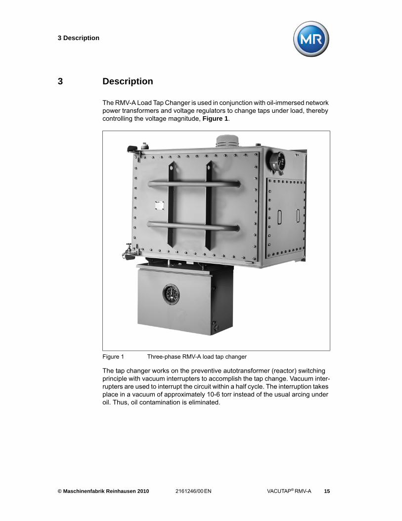
The RMV-A Load Tap Changer is used in conjunction with oil-immersed network power transformers and voltage regulators to change taps under load, thereby controlling the voltage magnitude, Figure 1.
The tap changer works on the preventive autotransformer (reactor) switching principle with vacuum interrupters to accomplish the tap change. Vacuum inter-rupters are used to interrupt the circuit within a half cycle. The interruption takes place in a vacuum of approximately 10-6 torr instead of the usual arcing under oil. Thus, oil contamination is eliminated.
Figure 1 Three-phase RMV-A load tap changer

3 Description
16 VACUTAP® RMV-A 2161246/00 EN © Maschinenfabrik Reinhausen 2010
3.1 Design
The RMV-A load tap changer is a three-phase design with full insulation bet-ween phases and to ground, Figure 2.
It consists of an oil compartment containing tap and change-over selectors (reversing or coarse/fine), vacuum interrupters and by-pass switches, a sepa-rately housed drive mechanism/cam switch assembly and other accessories as required by customer specification. Each phase consists of a tap selector, a change-over selector and a vacuum interrupter with bypass switch positioned on a vertical insulating panel. Three of these phase assemblies are connected with tie rods and mounted rigidly from the bottom of the tap changer oil compart-ment. All switching elements involved in the tap change operation, tap and changeover selectors, vacuum interrupters and by-pass switches of all phases, are driven by one main shaft from the drive mechanism.
The vacuum interrupter drive assembly is a cam-action, spring-driven mecha-nism which moves an operating rod when opening and closing. The operating rod is connected to the vacuum interrupter moving contact.
Figure 2 Tap changer oil compartment

3 Description
© Maschinenfabrik Reinhausen 2010 2161246/00 EN VACUTAP® RMV-A 17
The vacuum interrupter consists of a stationary and a moving contact enclosed in a vacuum-tight, ceramic insulating envelope, Figure 3.
The moving contact is sealed through flexible metal bellows protected from the arc by a shield. A metal shield surrounds the contacts, forming an arc chamber and condensing surface to collect vaporized contact material which arises during arcing.
The motor drive/cam switch assembly is normally housed in a separate air com-partment and is accessible through a weatherproof, hinged door. Optionally, the compartment can be lowered to ground level.
Figure 3 Vacuum interrupter, schematic layout

3 Description
18 VACUTAP® RMV-A 2161246/00 EN © Maschinenfabrik Reinhausen 2010
3.2 Operation
The tap changer operation is divided into three major functions, Figure 4.
• Arc interruption and reclosing by use of the vacuum interrupters in conjunc-tion with the associated bypass switches.
• Selection of the next position by the tap selector assemblies in proper sequence with the operation of the vacuum interrupters and by-pass swit-ches.
• Operation of reversing or coarse/fine selector in order to double the number of tap positions.
The tap changer is operated by a motor drive mechanism which rotates the main drive shaft through a reduction gear. A bevel gear assembly drives the operating mechanism inside the oil compartment. This gear unit distributes the input torque to the three horizontal insulating drive shafts assuring a precise operational sequence.
The selector shaft is driven by a geneva gear mechanism which also provides the pinion for the geneva gear segment of the reversing switch shaft. A crank mechanism drives the vacuum/by-pass switch shaft.
When moving from one tap position to the next, one set of by-pass switch con-tacts opens, while the second one stays closed, routing the current through the vacuum interrupter just prior to its operation. The vacuum interrupter opens by a spring-operated mechanism before the corresponding moving tap selector contact selects the next tap.
After the vacuum interrupter recloses under spring force and is locked into posi-tion, the by-pass switch closes shunting the vacuum interrupter, thus comple-ting the tap change operation.
The tap selector connects the preventive autotransformer alternately into bridging (F) or nonbridging position (A). The reversing or coarse/fine switch operates only when changing from position 1L to N or N to 1L, Figure 4.

3 Description
© Maschinenfabrik Reinhausen 2010 2161246/00 EN VACUTAP® RMV-A 19
Figure 4 Typical winding layout with LTC on position 16L with tap sequence to position 15 L

3 Description
20 VACUTAP® RMV-A 2161246/00 EN © Maschinenfabrik Reinhausen 2010
3.3 Tap Selector
The tap selector consists of one contact arm operated by geneva gear, Figure 5.
The geneva gear also locks the movable contacts on position between opera-tions. The stationary contacts are equally spaced forming a circle on the vertical insulating panel. They are connected by bus bars to a cast epoxy terminal board which becomes the interface between tap changer and transformer. The statio-nary contacts and the inner collector rings are silverplated.
Each moving contact assembly consists of parallel contact fingers. They are spring-loaded and digitally calibrated prior to assembly to provide safe contact force not only during normal operating but also during shortcircuit conditions.
Figure 5 Tap selector, by-pass switch and change-over selector, three-phase assembly

3 Description
© Maschinenfabrik Reinhausen 2010 2161246/00 EN VACUTAP® RMV-A 21
3.4 Change-over Selector (Reversing or Coarse/Fine)
The silverplated stationary contacts of the change-over selector are mounted on the vertical insulating panel adjacent to the tap selector assembly, Figure 5.
The change-over selector moving contact assembly is of the same design as the tap selector moving contact assembly but uses an increased number of par-allel contact fingers.
3.5 Vacuum Interrupter
The vacuum interrupter assembly of each phase is mounted vertically on one side of the insulating panel, Figure 6. Vacuum filling, therefore, is not required when oil is replaced in the field. Cam action drives the vacuum interrupter through a spring mechanism which latches at its end positions. The mechanism provides a direct drive by its operating rod to the vacuum interrupter contact, both moving in the same action line. The interrupter is locked in the open posi-tion while the tap selector changes taps. Upon completion of the tap selection, the interrupter mechanism unlocks and the moving contact recloses under posi-tive spring force. Opening and closing speeds of the vacuum interrupter are dashpot controlled.
Figure 6 Vacuumm interupter, single phase assembly
3 Description
22 VACUTAP® RMV-A 2161246/00 EN © Maschinenfabrik Reinhausen 2010
3.6 By-Pass Switch
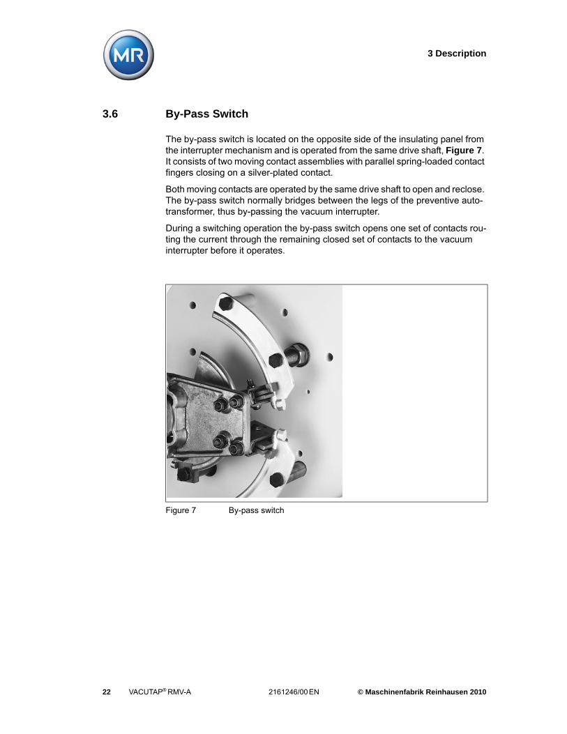
The by-pass switch is located on the opposite side of the insulating panel from the interrupter mechanism and is operated from the same drive shaft, Figure 7. It consists of two moving contact assemblies with parallel spring-loaded contact fingers closing on a silver-plated contact.
Both moving contacts are operated by the same drive shaft to open and reclose. The by-pass switch normally bridges between the legs of the preventive auto-transformer, thus by-passing the vacuum interrupter.
During a switching operation the by-pass switch opens one set of contacts rou-ting the current through the remaining closed set of contacts to the vacuum interrupter before it operates.
Figure 7 By-pass switch

3 Description
© Maschinenfabrik Reinhausen 2010 2161246/00 EN VACUTAP® RMV-A 23
3.7 Monitoring System
A unique monitoring system is utilized to protect the LTC in the unlikely event that a vacuum interrupter fails to interrupt and transfer the load current during a tap change operation, Figure 8.
Figure 8 Monitoring system schematic diagram
WARNING
Do not operate the LTC without this monitoring system properly connected and functional if the transformer is energized. Follow the test procedures outlined in Chapter 4.4.3.
During operation, if the monitoring system trips, do not reset until the LTC has been inspected and the cause of the trouble corrected. Failure to adhere to these requirements can lead to property damage and/or personal injury.
Please contact Reinhausen Manufacturing for assistance and refer to Chapter 8 for further details.

3 Description
24 VACUTAP® RMV-A 2161246/00 EN © Maschinenfabrik Reinhausen 2010
Three saturating current transformers in the moving contact leads of the vacuum interrupters are provided. The electrical signal from the current trans-former is transmitted by fibre optic cable to the monitoring circuit board. These cables must be handled with reasonable care. DO NOT BEND OR COIL these cables to a radius smaller than 100 mm (3.94”). Overbending will damage the cable and destroy its ability to carry a light pulse.
The system monitors the current in all three phases at a threshold of less than 20 amperes after the interrupters are open but prior to the movement of the tap selector contacts. The logic circuit evaluates these signals and protects the LTC in case of vacuum interrupter failure by operating a bistable output relay. This relay operation returns the LTC to the original position before the tap selector opens the circuit and prevents further operations.
The monitoring system’s control and indicating components are located inside the door of the drive mechanism cabinet. It contains the electronic circuitry, power supply, 86 L, 86 C and 86 R trip relays, SP supervision power relay, 3 red and 3 yellow LEDs and a green LED, a TEST push-button (green) and a RESET push-button (red).
The red LEDs indicate energizing of the associated trip relays. The yellow LED’s indicate energizing of the SP relay denoting loss of CT signal for the associated phase. The green LED indicates operability of the system. The green TEST push-button is used to test the internal circuitry of the monitoring system.
Pressing the TEST push-button simulates a failure condition of all three phases, energizes the trip relays and lights the three red LEDs. After testing the monito-ring system must be reactivated by pressing the red RESET push-button.
CAUTION
The monitoring system is functional only when the RMV-A load tap changer is operated by control power (either by manual control switch raise/ lower or automatically). It does not function if the unit is operated by hand cranking. Therefore, never hand crank the unit if the transformer is energized as damage to the transformer and/or personal injury may result if any of the vacuum interrupters fails to interrupt.
An optional mechanical interlock is available to prevent hand cranking if a vacuum interrupter failure occurs or upon loss of control power. As with any safety device, the mechanical interlock should not be intentionally defeated or tampered with.

3 Description
© Maschinenfabrik Reinhausen 2010 2161246/00 EN VACUTAP® RMV-A 25
The system should be tested at installation and scheduled examination inter-vals. The physical layout of the monitoring system circuit board is shown in Figure 12.
3.8 Drive Mechanism/Cam Switch Assembly
The drive mechanism and cam switch control assembly are housed in a sepa-rate air compartment attached to the bottom of the tap changer oil compartment, Figure 9. The entire assembly, together with the position indicator, motor capa-citors and terminal blocks, is mounted to a detachable mounting plate affixed to the rear wall of the motor drive housing.
The drive mechanism is powered by a single-phase, 208 - 240 Volt, 60 Hertz, permanent split capacitor motor which is flange-mounted to a self-contained reduction gear unit. This gear unit is grease filled and sealed at the factory to eliminate the need for subsequent lubrication. Its output shaft couples directly to the tap changer main shaft which extends through the tap changer oil com-partment bottom. An auxiliary reduction gear driven from this gear unit operates the factory preset cams and the position indicator.
The air compartment is accessible through a front mounted, weather-proof, hin-ged door. The LTC tap position indicator is visible through a viewing port in the door.
The position indicator has two red drag hands indicating the maximum and mini-mum positions (raise and lower) of the actual operating range.
Figure 9 Drive mechanism cam switch assembly, hinged door open showing monitoring system and handcrank

3 Description
26 VACUTAP® RMV-A 2161246/00 EN © Maschinenfabrik Reinhausen 2010
A handcrank coupling with interlocking switch is provided at the main gear unit and can be used with the air compartment door open.
A modified version of the drive mechanism/cam switch assembly with weather-proof drive shaft seal on top of the housing allows for separate attachment of the air compartment to the transformer main tank at a lower level, if required. In this case, a single drive shaft couples tap changer and drive mechanism. Its length may be varied according to customer specifications (max. shaft length 2,500 mm (98.4 in.).
The drive mechanism requires a separate customer supplied control cabinet with appropriately sized motor control relays and protective circuit breaker. On request this control cabinet can be supplied by Reinhausen. Please consult wiring diagram supplied with each order for specification guidelines concerning motor control relays and protective circuit breaker.
3.8.1 Option
The drive mechanism assembled on the mounting plate including cam switch assembly, monitoring system circuit board, position indicator, drive shaft and required fittings is also available to be mounted into the transformer control cabinet by the customer.

4 Installation
© Maschinenfabrik Reinhausen 2010 2161246/00 EN VACUTAP® RMV-A 27
4 Installation
4.1 Receiving, Handling and Storage
Before mounting on the transformer the tap changer oil compartment and the drive mechanism air compartment should be opened and inspected for damage which may have occurred in shipment due to rough handling. If shipping damage is evident, file a claim with the transporting company. The sales office of Reinhausen Manufacturing should be notified promptly of damage occurring during shipment from its plant.
No special handling of the tap changer is required other than that accorded the transformer in general. The tap changer is shipped from Reinhausen Manufac-turing filled with dry nitrogen under positive pressure. If the tap changer is ope-ned and the nitrogen fill is lost the tap changer oil compartment must be purged and filled with dry nitrogen at a pressure not exceeding 4 psi, when stored again indoors.
The LTC and drive mechanism are not prepared for storage in an unheated buil-ding or outdoors. Such conditions require:
• filling the LTC tank with clean, dry oil and the gas space with dry nitrogen,
• weather protecting of the exterior of the tank and terminal board,
• heating the drive mechanism air compartment by connecting the built-in space heater to power.

4 Installation
28 VACUTAP® RMV-A 2161246/00 EN © Maschinenfabrik Reinhausen 2010
4.2 Mechanical Set-up
4.2.1 Attaching the Oil Compartment
Check the size of the opening in the transformer main tank. For minimum tank opening dimensions see customer dimensional arrangement drawing. Weld the LTC compartment to the transformer main tank taking care that the weld is oil-tight, pressure and vacuum resistant.
4.2.2 Mounting the Drive Mechanism Air Compartment
The LTC and motor drive are shipped on separate pallets in the neutral position. The LTC and motor drive serial numbers should be checked prior to assembly to ensure they match.
Prior to shipment the LTC is locked in the neutral position by a cotter pin which is inserted through the boss and the drive shaft extension on the bottom of the tank. This cotter pin should not be removed until the motor drive is ready for assembly to the LTC.
The motor drive unit is also shipped in the neutral position. Confirm this by checking that:
• the position indicator is on neutral
• the cam switch timing wheel is at zero degrees
CAUTION
Welding adjacent to the epoxy terminal board may distort its mounting surface and cause damage to the terminal board or its oil seal.
The transformer manufacturer is responsible for mounting the LTC on a trans-former tank wall that is designed to withstand normal test and operating pres-sures (15 psi maximum). A 0.25-in. oil tight weld is required around the outside perimeter of the LTC mounting flange. Welding on the transformer side of the LTC is not required.
WARNING
Do not turn the LTC input shaft nor the drive mechanism output shaft until they are coupled with each other. Coupling LTC and motor drive in non-matching positions may cause mechanical damage.

4 Installation
© Maschinenfabrik Reinhausen 2010 2161246/00 EN VACUTAP® RMV-A 29
4.2.2.1 Standard Mounting (Attachment to the LTC oil compartment)
The LTC and motor drive must be coupled in the neutral position per drawing 4D32012 (see appendix).
4.2.2.2 Detached (Ground Level) Mounting (Attachment to the transformer main tank)
This version requires, provided by the transformer manufacturer, a mounting support on the transformer main tank. The support is fastened to the rear of the drive mechanism housing.
The LTC and motor drive must be coupled in the neutral position per drawing 4D32009 (see appendix).
4.3 Electrical Connections
4.3.1 Connecting the Tap Leads to the LTC
Connect tap leads to the proper LTC terminal on the epoxy terminal board. For terminal location and designation see dimensional arrangement drawing.
4.3.2 Connecting the Monitoring System and the Drive Mechanism
The drive mechanism is to be wired according to the wiring diagram which is supplied with each order. To connect the monitoring system, insert the cable plug from the motordrive cabinet into the receptacle on the bottom of the LTC tank per drawing 4D32012 (see appendix).
4.4 Test Procedures
4.4.1 Manual Test Procedures
Open the LTC compartment and the drive mechanism. Insert the handcrank into the guide lever and engage the motor drive. Sequence check the LTC operation by hand cranking one step in the lower direction, position N to 1L (see sequence chart in drawing DD00001 of appendix). This movement requires 7.5 handcrank revolutions.

4 Installation
30 VACUTAP® RMV-A 2161246/00 EN © Maschinenfabrik Reinhausen 2010
While hand cranking from N to 1L (counter-clockwise) observe that the by-pass switch P2 opens, then the vacuum interrupter trips open and the tap selector moving contact P1 (nearest to the insulating panel) moves from M to 11. At the same time as the tap selector, the changeover selector will move from B to A. Continue cranking and the vacuum interrupter will reclose and finally the bypass switch P2 closes, positioning the tap changer in “on position”. (Both by-pass moving contacts are fully engaged to their respective stationary contacts.)
Hand crank in the raise direction (clockwise) back to neutral (position N). The same events should take place in the same order as above except that the movement is from 11 to M and from A to B.
Then check the LTC operation by hand cranking from position N to 1R. While hand cranking in the raise direction (clockwise) observe that the by-pass switch P3 opens, then the vacuum interrupter trips open, followed by the tap selector moving contact P4 (furthest from the insulating panel) moving from M to 4. Con-tinue hand cranking and the vacuum interrupter will reclose, then the by-pass switch P3 will reclose, positioning the LTC in “on position”.
Hand crank in the lower direction (counter-clockwise) back to neutral (position N). The same events should take place in the same order as above except that the movement is from 4 to M.
Withdraw the handcrank and place it in the storage holder provided.
4.4.2 Motorized Test Operations
Operate the tap changer with the drive mechanism connected to electrical power. Do not run more than 120 consecutive operations or damage to the motor may occur.
Observe the engagement of tap and change-over selector moving contacts for smooth, non-binding operation. Observe closure of by-pass switch.
Observe the engagement of tap selector moving contacts for smooth, non-bin-ding operation. Observe closure of by-pass switch.
Extended operation of the LTC without oil is not recommended. However, the LTC may be run once to both limits and back to neutral position for test purpo-ses. When running the LTC electrically it typically stops between 0° to 18° on the timing wheel. This is a normal condition.

4 Installation
© Maschinenfabrik Reinhausen 2010 2161246/00 EN VACUTAP® RMV-A 31
Make sure that both the monitoring system and the drive mechanism are con-nected to power. Make sure that the motor control breaker is closed and the handcrank is in its storage holder. Place the monitoring system into “Mainte-nance Mode” as per Chapter 8.1 of this manual. Operate the LTC by closing the raise/ lower switch one step from neutral position toward the lower limit. Check the movement of the position indicator to confirm that the motor is con-nected properly. The drive mechanism should operate and stop “on position”.
Operate the LTC one step of at a time from position N toward the lower limit. Open the handcrank interlock switch by lifting the handcrank guide lever while operating the LTC. The tap changer should not operate. Release and continue with the operation toward the lower limit. Stop on the lowest limit position (posi-tion 16L). With one hand on the motor control breaker, close the raise/lower switch in the lower direction. The drive mechanism should not run. If it does, turn off the circuit breaker at once because either the limit switch timing or connec-tions are wrong.
Remove the handcrank from its storage holder and insert. Try to hand crank the tap changer in lower direction. The mechanical stop should operate in approxi-mately 3 handcrank revolutions. This can be felt readily on the handcrank. Do not force the handcrank.
Run the tap changer one step at a time in the raise direction and repeat the checks as above in the raise limit (position 16R).
Upon completion of the checks return the tap changer to the assembly position (position N), return the handcrank to its storage holder. Close the drive mecha-nism air compartment.
4.4.3 Monitoring System Tests
Open the drive mechanism door for access to the system. There is a green LED which indicatesoperability of the system. Two push-buttons are provided, one red to reset and one green to test. Figure 10 shows the layout of these items.
Check the green LED to ensure that the monitoring system is operative.
CAUTION
The monitoring system is functional only when the RMV-A load tap changer is operated by control power (either by manual control switch raise/ lower or automatically). It does not function if the unit is operated by hand cranking. Therefore, never hand crank the unit if the transformer is energized as damage to the transformer and/or injury to the operator may result if any of the vacuum interrupter tails to interrupt.

4 Installation
32 VACUTAP® RMV-A 2161246/00 EN © Maschinenfabrik Reinhausen 2010
4.4.3.1 Power-off Test at the Transformer Control Cabinet
Open the transformer control cabinet. The green lamp 86 GL in the control cabi-net should be on indicating that the monitoring system is energized.
Drop control power. Remove cover from monitoring system circuit board. Inter-rupt the power supply to the circuit board by removing the 0.25 A fuse. Rein-state control power. The 86 GL lamp should then be off and the red lamp 86 RL, on. Try to operate the LTC drive mechanism. It should not start. Reinstall the monitoring system fuse and it’s cover. Close the transformer control cabinet
4.4.3.2 Operational Tripping Test
Connect a variable CT to busbar P2 and the stationary end of the flexible con-nector on the moving contact of one of the vacuum interrupter assemblies, for example left phase, Figure 11. The CT should be able to drive a current of at least 20 Amperes.
A monitoring system trip test set is available, reference Chapter 9.
Place monitoring system into “Maintenance Mode” so that all three yellow LED’s are flashing slowly, Chapter 8.1. Raise the CT input voltage to drive a primary current of approximately 20 A. Start the drive mechanism in one direction. The 86 L relay should trip, the associated red LED should light, the drive mechanism
Figure 10 Monitoring system, cover removed
Green LED
Green push button=TESTRed push button=RESET
3 red and 3 yellow LEDsRight, Center, Left

4 Installation
© Maschinenfabrik Reinhausen 2010 2161246/00 EN VACUTAP® RMV-A 33
should stop and return to its previous position. The moving selector contact must not disconnect from the stationary during the process. The drive mecha-nism must not be operable in either direction, until the monitoring system is reset.
Perform same test procedure with the vacuum interrupter assemblies of center and right phase. Observe tripping of 86 C and 86 R relays. Be sure to reset the monitoring system so that all 86 relays are untripped and all red lights out. Close the LTC compartment access door.
Do not overtighten the LTC access door nuts. These nuts should be tightened to a maximum torque of 15 Nm (11.1 ft. lbs.), which corresponds to a compres-sion of the gasket to 5/16” thickness.
Figure 11 CT connection for test

4 Installation
34 VACUTAP® RMV-A 2161246/00 EN © Maschinenfabrik Reinhausen 2010
4.5 Oil Filling/Transformer Vacuum Processing
In preparation for factory testing of the transformer at the maximum tap changer voltage rating (15 kV, 25 kV or 69 kV), vacuum fill the LTC tank with oil to the proper level prior to initiating any transformer tests.
1. Make the oil input and vacuum connections to the compartment. Remove and plug the 1/4-in. coupling to the dehydrating breather system.
2. Hold a vacuum of 1 torr, or better, on the tap changer compartment for 2 hours prior to filling. Continue to hold this vacuum during filling. Degassed oil will facilitate this process.
3. Break the vacuum with dry, inert gas.
4. Take three oil samples from the LTC oil compartment and test for breakdown voltage. All three samples should have a minimum breakdown voltage of 30 kV by ASTM D 877 or 28 kV by ASTM D 1816. Moisture content should not exceed 20 ppm by ASTM D1533.
5. Run the tap changer with motor power through the complete range limit-to-limit, 16 L to 16 R.
6. Reclose the compartment openings.
During transformer vacuum processing (druing) the LTC should be considered part of the transformer. Therefore, the tap changer and transformer gas spaces should be connected together through the vent plug. The differential pressure across the terminal board and its gasket system will then be zero during the entire processing cycle. Auxiliary devices, e.g. dehydrating breather, sudden pressure relay, etc., must be removed or disconnected during processing or filling to prevent damage due to oil “flooding”. The sudden pressure relay can also be damaged by rapid pressure changes (consult the instruction leaflet). The vacuum should always be broken with dry, inert gas to prevent moisture contamination.
The RMV-A tank is designed to withstand a full vacuum. The terminal board is designed to withstand a maximum differential pressure of 18 psi. This allows for full vacuum in the LTC tank with a maximum positive pressure of 3.3 psi from the transformer side of the terminal board.

5 Maintenance-Free Schedules and Service
© Maschinenfabrik Reinhausen 2010 2161246/00 EN VACUTAP® RMV-A 35
5 Maintenance-Free Schedules and Service
Prior to initial energization of the transformer, perform tests and examinations per Chapter 4.4.3 and 5.4.2.
Because of its basic design, the RMV-A Load Tap Changer will require a mini-mum of maintenance. However, as with any mechanical device, it should receive periodic examination.
5.1 Maintenance-Free Intervals
The RMV-A is a Maintenance-Free Load Tap Changer through 250,000 opera-tion count intervals or through 5 year time spans, whichever occurs first.
The Maintenance-Free interval can become strictly operation count based regardless of time span by use of the Model 'B' monitoring system. Refer to Chapter 8 for detailed information.
The Maintenance-Free intervals, whether time-based or operations count-based, will only need complementing by checks (annually) as follows:
Routine site visits should include as good practice the following:
Test Check Reference
Oil Sampling Check for dielectric, combusti-ble gases and water content
Chapter 4.5
VIM System Test Check circuit board ‘test & reset’ function; simulated monitoring runback & ‘power off’ test
Chapter 8.4, 4.4.3
Motor drive condition Check heater & accessory operation; general mechanical condition
Chapter 4.4.2
Table 3 Annual checks
Test Check Reference
Dehydrating Breather check
Check for oil level and desic-cant material color
Chapter 7.3,Chapter 7.4
Check for oil leaks All areas with seals or gaskets that retain oil should be exami-ned
Table 4 Routine checks

5 Maintenance-Free Schedules and Service
36 VACUTAP® RMV-A 2161246/00 EN © Maschinenfabrik Reinhausen 2010
5.2 Taking the LTC out of Service
1. De-energize the transformer and ground all external bushings.
2. Open the drive mechanism motor control breaker.
3. Record the number of operations on the tap changer operations counter.
5.3 Draining the Oil
1. Take a tap changer oil sample.
2. Test and record the breakdown voltage.
3. Remove the vent plug on top of the LTC compartment and drain the oil.
If the drained oil is to be reused it should be pumped through a filter press to remove the small amount of carbon and metallic particles produced by the swit-ching duty of the by-pass switch and the normal wear of the mechanism.
The oil should be stored in clean, dry containers if it is to be reused.
Open the LTC front inspection door. Check the door gasket for signs of deteri-oration. Replace with a new gasket if necessary.
CAUTION
Transformer oil should always be handled as a flammable liquid. LTC tanks may, under some conditions, accumulate explosive gasses. Filtering and handling the oil may generate static electricity. A damaging explosion could result if any electrical discharge takes place in an explosive gas mixture. Safety precautions should include purging the gas space with dry nitrogen before filtering and grounding the transformer, its bushings, and all oil handling equipment.

5 Maintenance-Free Schedules and Service
© Maschinenfabrik Reinhausen 2010 2161246/00 EN VACUTAP® RMV-A 37
5.4 Internal Examination
1. Check the LTC compartment floor and horizontal surfaces for debris that might indicate abnormal wear.
2. Check all sliding surfaces for signs of excessive wear.
Make a general inspection of the tightness of bolts and nuts on those parts which are subjected to mechanical shock and vibrations during the tap change operation.
CAUTION
The monitoring system uses FIBRE OPTIC CABLES inside the LTC to transmit signals to the electronic control box. These cables must be handled with reasonable care. DO NOT BEND OR COIL these cables to a radius smaller than 100 mm (3.94"). Overbending will damage the cable and destroy its ability to carry a light pulse.
Figure 12 By-pass contact wear evaluation

5 Maintenance-Free Schedules and Service
38 VACUTAP® RMV-A 2161246/00 EN © Maschinenfabrik Reinhausen 2010
5.4.1 By-Pass Switch
Check the condition of the by-pass switch contacts P2 and P3, Figure 7. These contacts are subjected to light arcing as they re-route the tap changer current to the vacuum interrupter during a tap change operation. For this reason the sta-tionary and moving contact assemblies are equipped with copper-tungsten tips.
5.4.2 Vacuum Interrupter Examination
Inspect the condition of the flexible connector for broken strands.
5.4.2.1 Mechanical Test
To open the vacuum interrupters, crank the LTC between position N and 1L (timing wheel 180°). At the end of the power spring lift the lever and watch the operating rod move down until it engages the latch, Figure 13. Repeat a few times to get a feel for the movement and the force required.
Both moving and arcing by-pass contact assemblies must be replaced when the area of erosion is closer than 8 mm (0.3") to the end of the copper-tungsten tip on any location on the stationary by-pass contact P2 or P3, Figure 12.
CAUTION
During this check lift the lever only until the operation rod just touches the edge of the latch. Beyond that point the additional force required to operate the latch will show to a misleading result.
Figure 13 Vacuum interrupter mechanical test

5 Maintenance-Free Schedules and Service
© Maschinenfabrik Reinhausen 2010 2161246/00 EN VACUTAP® RMV-A 39
5.4.2.2 Contact Erosion Indicator
Due to the expected very small contact erosion (less than 2 mm during the life of the vacuum interrupter) a contact erosion indicator is not provided. A much more precise and reliable method to determine the contact wear is to measure the gap between the operating rod and the lever (in the following paragraph this gap is called "anvil gap") using a set of feeler gages.
Recording the anvil gap at commissioning and subsequent routine mainte-nance will provide the best estimate of the remaining contact life.
To measure the anvil gap, crank the LTC off position until the lever is engaged to the latch. This means, until the tripping edge of the lever is seated against the latch, but the vacuum interrupter is still closed, Figure 14.
When the load tap changer is opened for the first time and at subsequent ins-pections, the anvil gap should be measured to allow the evaluation of the con-tact wear.
The vacuum interrupter is rated for 750,000 operations at full load (overload conditions may reduce the operational life of the vacuum interrupter). However, when the anvil gap is equal or less than 0.5 mm, the vacuum interrupter is worn beyond its limit and must be replaced. Independently from the contact erosion measurement the vacuum interrupter must be replaced after 750,000 opera-tions due to mechanical wear.
Figure 14 Anvil Gap
5 Maintenance-Free Schedules and Service
40 VACUTAP® RMV-A 2161246/00 EN © Maschinenfabrik Reinhausen 2010
5.4.2.3 Hi-Pot Test
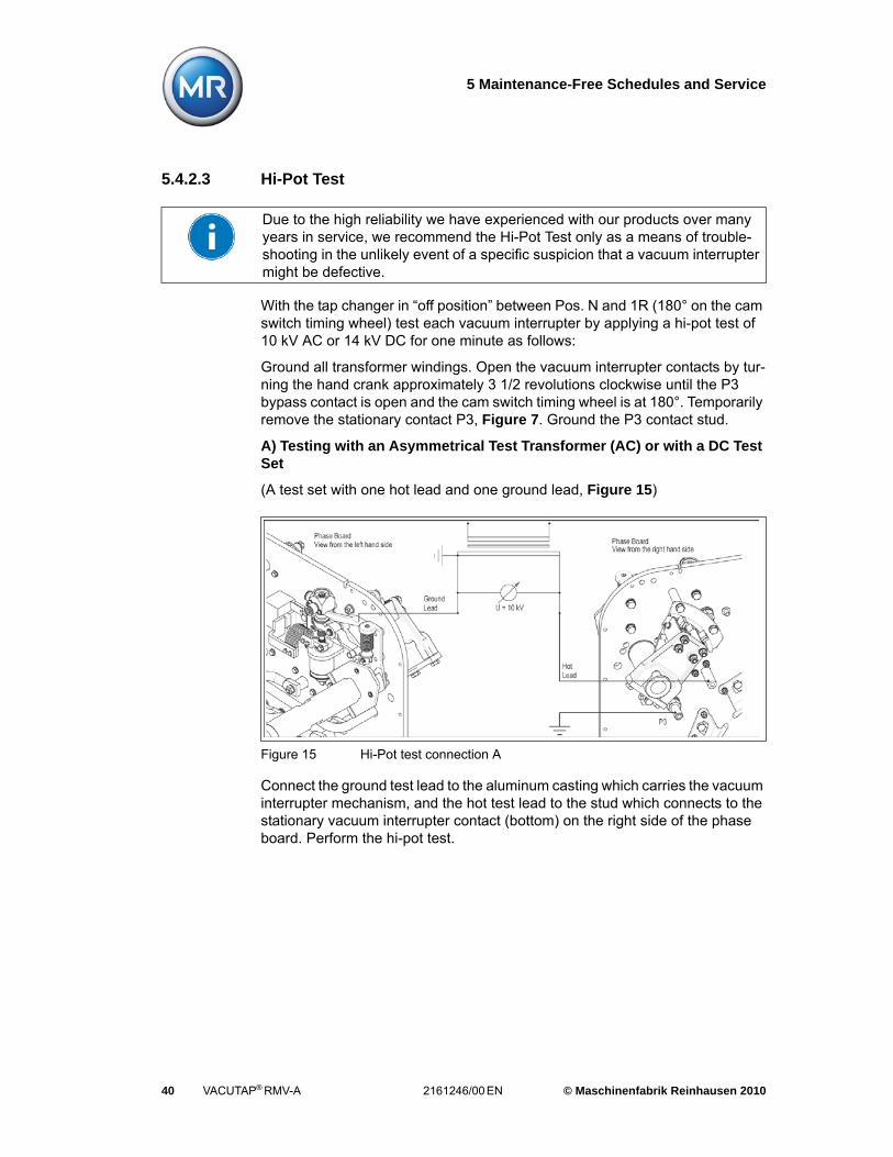
With the tap changer in “off position” between Pos. N and 1R (180° on the cam switch timing wheel) test each vacuum interrupter by applying a hi-pot test of 10 kV AC or 14 kV DC for one minute as follows:
Ground all transformer windings. Open the vacuum interrupter contacts by tur-ning the hand crank approximately 3 1/2 revolutions clockwise until the P3 bypass contact is open and the cam switch timing wheel is at 180°. Temporarily remove the stationary contact P3, Figure 7. Ground the P3 contact stud.
A) Testing with an Asymmetrical Test Transformer (AC) or with a DC Test Set
(A test set with one hot lead and one ground lead, Figure 15)
Connect the ground test lead to the aluminum casting which carries the vacuum interrupter mechanism, and the hot test lead to the stud which connects to the stationary vacuum interrupter contact (bottom) on the right side of the phase board. Perform the hi-pot test.
Due to the high reliability we have experienced with our products over many years in service, we recommend the Hi-Pot Test only as a means of trouble-shooting in the unlikely event of a specific suspicion that a vacuum interrupter might be defective.
Figure 15 Hi-Pot test connection A

5 Maintenance-Free Schedules and Service
© Maschinenfabrik Reinhausen 2010 2161246/00 EN VACUTAP® RMV-A 41
B1) Testing with a Symmetrical Center-Tapped Test Transformer
(A test set with two hot leads and with test voltage of 20 kV or higher, Figure 16)
Connect the ground test lead to the aluminum casting which carries the vacuum interrupter mechanism, and the hot test lead to the stud which connects to the stationary vacuum interrupter contact (bottom) on the right side of the phase board. Perform the hi-pot test.
B2) Testing with a Symmetrical Center-Tapped Test Transformer
(A test set with two hot leads and with maximum test voltage lower than 20 kV, Figure 17)
Figure 16 Hi-Pot test connection B1
Figure 17 Hi-Pot test connection B2

5 Maintenance-Free Schedules and Service
42 VACUTAP® RMV-A 2161246/00 EN © Maschinenfabrik Reinhausen 2010
Temporarily disconnect the flexible connector from the bus bar shunt connector P2 carrying the CT and tie it to the aluminum housing. Apply the two hot test leads as shown and perform the hi-pot test. This is a special test method when the maximum voltage of the test transformer is less than 20 kV.
5.4.2.4 Hi-Pot Test Spare Parts Kit
Reinhausen Manufacturing offers spare parts kits to replace lock nuts, lock tabs and other not reusable items after the Hi-Pot test. For ordering information refer to the spare parts list in Chapter 9 of this manual.
Reassemble the previously disconnected or removed items. Use new locking hardware as provided in the respective spare parts kit.
Once the Hi-Pot test has been completed bring the LTC back to “on position”.
A vacuum Interupter Hi-Pot Test Set is available; reference spare partsChapter 9 of this manual.
5.5 Preparing the LTC for Service
Examine the vacuum interrupter as per Chapter 5.4.2.1.
Wipe the LTC compartment clean to remove all dirty oil, metallic fall-out and moisture that may have condensed on the walls and insulating surfaces during the time the oil compartment was open.
Ensure the drive mechanism and monitoring system are operating properly. Perform test operations of the drive mechanism and a monitoring system test according to Chapter 4.4.
Close the LTC compartment.
Using a filter press fill the LTC compartment with clean, dry oil to the proper level. Vacuum filling is not required during field service.
Make the oil fill connections to the LTC drain valve. Make sure the vent opening is unplugged. Remove and plug the 1/4" coupling to the dehydrating breather system.
After oil filling reclose the LTC compartment openings and reconnect the dehy-drating breather system.
Do not overtighten the LTC inspection door gaskets. Inspection door nuts should be tightened to a maximum torque of 15 Nm (11.1 ft. lbs.), which corre-sponds to a compression of the gasket to 5/16”.

5 Maintenance-Free Schedules and Service
© Maschinenfabrik Reinhausen 2010 2161246/00 EN VACUTAP® RMV-A 43
Run the Tap Changer with motor power from the neutral (or assembly position) to position 16L (or the lowest position) for approximately 100 operations without pausing. Return to the neutral position.
Let the tap changer sit de-energized for one hour to allow gas bubbles to dissi-pate from the oil.
Take three oil samples and test for break-down voltage. All three should have a minimum breakdown voltage of 30 kV by ASTM D877 or 28 kV by ASTM D1816. Moisture content should not exceed 20 ppm by ASTM D1533.
The dehydrating breather should be checked to verify that the desiccant is dry and the oil level in the clear plastic oil collection cell is between the two fill level lines (refer to drawing DD10008 in the appendix).


6 Replacement of the Vacuum Interrupter Assembly
© Maschinenfabrik Reinhausen 2010 2161246/00 EN VACUTAP® RMV-A 45
6 Replacement of the Vacuum Interrupter Assembly
Due to the high life expectancy of the vacuum interrupter a replacement is necessary only after 750,000 operations. After this period the contacts may not have reached their maximum erosion, but in order to insure continued reliability the vacuum interrupter assembly must be replaced as a unit. With this all the parts subjected to mechanical wear are replaced as well. Reinhausen Manufac-turing offers a pre-assembled replacement kit. Refer to DD10005 in the appen-dix and Figure 18 through Figure 24 for the item numbers used in the following instructions.
6.1 Removing the Old Vacuum Interrupter Assembly
When removing the old vacuum interrupter assembly carefully observe the con-figuration of the parts and hardware during disassembly so that reinstallation can be completed easily and correctly. To remove the old vacuum interrupter proceed as indicated below.
1. Remove the coupling assembly (90) which connects the vacuum/by-pass switch shaft assembly to the operating mechanism, Figure 18.
CAUTION
The Fibre Optic Cables must be handled with reasonable care. DO NOT BEND OR COIL these cables to a radius smaller than 100mm (3.94"). Overbending will damage the cable and destroy its ability to carry a light pulse.
CAUTION
If the vacuum interrupter is being removed for reasons other than replacement DO NOT TWIST the moving contact. This may damage the bellows and cause the vacuum interrupter to fail.

6 Replacement of the Vacuum Interrupter Assembly
46 VACUTAP® RMV-A 2161246/00 EN © Maschinenfabrik Reinhausen 2010
2. Turn the shaft assembly 90°, so the the cam disk (5) points toward the door, Figure 19.
Figure 18 Coupling assembly (90)
Figure 19 Cam disk (5) pointing toward the LTC door

6 Replacement of the Vacuum Interrupter Assembly
© Maschinenfabrik Reinhausen 2010 2161246/00 EN VACUTAP® RMV-A 47
3. Unscrew the socket head screw (22) and lock washer (11) to take off the front guide (47), Figure 19.
4. Open the hex head screws (1) and disassemble the clamp (4),Figure 18.
5. Rotate the cam disk (5) toward the LTC door and set aside. Check that the socket head screw (15) is loose on the clamp (52), Figure 19, 21.
Figure 20 Removal / Installation of the vacuum interrupter assembly
Figure 21 Removal / Installation of the vacuum interrupter assembly
6 Replacement of the Vacuum Interrupter Assembly
48 VACUTAP® RMV-A 2161246/00 EN © Maschinenfabrik Reinhausen 2010
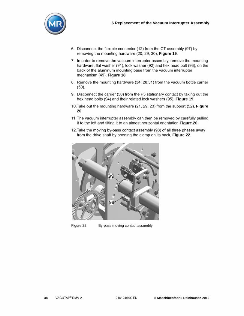
6. Disconnect the flexible connector (12) from the CT assembly (97) by removing the mounting hardware (20, 29, 30), Figure 19.
7. In order to remove the vacuum interrupter assembly, remove the mounting hardware, flat washer (91), lock washer (92) and hex head bolt (93), on the back of the aluminum mounting base from the vacuum interrupter mechanism (49), Figure 18.
8. Remove the mounting hardware (34, 28,31) from the vacuum bottle carrier (50).
9. Disconnect the carrier (50) from the P3 stationary contact by taking out the hex head bolts (94) and their related lock washers (95), Figure 19.
10.Take out the mounting hardware (21, 29, 23) from the support (52), Figure 20.
11.The vacuum interrupter assembly can then be removed by carefully pulling it to the left and tilting it to an almost horizontal orientation Figure 20.
12.Take the moving by-pass contact assembly (98) of all three phases away from the drive shaft by opening the clamp on its back, Figure 22.
Figure 22 By-pass moving contact assembly

6 Replacement of the Vacuum Interrupter Assembly
© Maschinenfabrik Reinhausen 2010 2161246/00 EN VACUTAP® RMV-A 49
Move the drive shaft towards the operating mechanism on the left until the bea-ring half shells (99) can be removed from the bore in the left and right phase board, Figure 23.
6.2 Installing the New Vacuum Interrupter Assembly
1. To install the new vacuum interrupter assembly, follow the steps previously described but in reverse order.
2. Insert new bearing half shells (99) and move the drive shaft back into its original location, Figure 23.
3. Reinstall the By-Pass stationary contact assemblies, Figure 22. Refer to Chapter 5.4.1 to decide if they need to be replaced with new ones.
Figure 23 Bearing half shells
Lock tabs and lock nuts should not be reused for reasons of reliability. Always use new lock tabs and lock nuts when reassembling the unit. Sufficient spare tabs and nuts are contained in our spare parts kit.
CAUTION
Avoid excessive twisting of the bellows during assembly and adjustment. Excessive twisting will reduce the mechanical life of the bellows or will fracture it, making the vacuum interrupter inoperative.

6 Replacement of the Vacuum Interrupter Assembly
50 VACUTAP® RMV-A 2161246/00 EN © Maschinenfabrik Reinhausen 2010
4. Careful not to damage the bellows of the vacuum interrupter insert the spare assembly in reverse order.
5. Tighten the fasteners (34, 28, 31) for the vacuum bottle carrier (50) and the connection to the P3 stationary contact (94, 95).
6. Insert the mounting hardware (91, 92, 93) on the back of the aluminum mounting base (49) and tighten.
7. Reassemble the mounting hardware (21, 29, 23) of the support (52), but do not fasten the socket head screw (15) to close the clamp yet.
8. Connect the flexible connector (12) to the CT assembly (97) using new lock nuts (30).
9. Check, if the operating rod (53) can move freely. For this refer to the mechanical test described in Chapter 5.4.2. If this is not the case, loosen the hardware on the back of the aluminum mounting base (49) and move it within the clearance of the bolt holes to improve the alignment of the operating rod (53) within the bearing (13).
10.Retighten the hardware. There should be no binding now.
11.Reassemble the new cam disk (5) using the new hardware (1, 2) and guide (47) with the fasteners (11) and (22).
12.Rotate the vacuum/by-pass switch shaft assembly back to "on position" and reconnect the coupling assembly (90) using new locking tabs (96).
13.Check that the By-Pass moving contact assemblies are centered in relation to the stationary contacts and the contact finger assemblies are floating within their carriers.
14.Align if necessary.

6 Replacement of the Vacuum Interrupter Assembly
© Maschinenfabrik Reinhausen 2010 2161246/00 EN VACUTAP® RMV-A 51
6.2.1 Adjustment of the Closing Travel
1. With the LTC "on position" measure the dimension "A" from the top of the brake cylinder (86) to the top of the operating rod (53) using a depth gage. Make sure to take the reading away from the M4 tap in the center of the ope-rating rod to avoid a false result, Figure 24.
2. Hand crank the LTC between positions until the vacuum interrupter opens. Continue hand cranking slowly until the operating rod is just retained by the latch (62) but the tang on the back of the lever (43) is not touching the latch (62) yet. Measure the dimension "B" from the top of the brake cylinder (86) to the top of the operating rod (53).
3. The closing travel "C" is calculated by subtracting "B" from "A" (C=A-B). "C" must be adjusted to 0.8 to 1 mm:
0.8 mm ≤ C ≤ 1.0 mm
4. The closing travel "C" is adjusted by rotating the vacuum interrupter (37) within the M18 tap of the carrier (50).
5. Loosen the clamping hardware (20, 29) and (28, 27) on the carrier (50) and the split nut (44) respectively. You may have to pry the split nut open until it can rotate freely on the moving contact stem of the vacuum interrupter.
6. Check that the socket head screw (15) is loose on the clamp (52). Carefully rotate the vacuum interrupter to adjust “C”. The pitch of the thread is 1.5 mm, i.e. one rotation of the vacuum interrupter translates to an axial movement of 1.5 mm. If “C” measured more than 1mm the interrupter must be moved up, if “C” measured less than 0.8 mm the interrupter must be moved down. Be careful not to loosen the operating rod (53) within the tap of the moving vacuum interrupter contact while turning it during the adjustment.
7. Tighten all loose hardware and check again for free movement of the operating rod.
Figure 24 Closing travel C

6 Replacement of the Vacuum Interrupter Assembly
52 VACUTAP® RMV-A 2161246/00 EN © Maschinenfabrik Reinhausen 2010
8. Using a feeler gage check and record the anvil gap. It should not be less than 2.5 mm (0.1"), Figure 14.
9. Perform several test operations between two tap positions to ensure the correct stroke of the vacuum interrupter moving contact. Perform the operations by hand cranking and observe the vacuum interrupter opening and closing.
10.Finally set the load tap changer to “on position”.
Refer to Chapter 4.4 and Chapter 5.5 for testing requirements prior to placing the LTC back inservice.

7 Dehydrating Breather Assembly
© Maschinenfabrik Reinhausen 2010 2161246/00 EN VACUTAP® RMV-A 53
7 Dehydrating Breather Assembly
The dehydrating breather is designed to remove moisture from the air breathed into the load tap changer. It consists of a cylindrical glass body, top connecting flange, bottom breather/trap and an exterior protective grate with three obser-vation ports.
7.1 Receiving
The breather is shipped detail with the dehydrating material placed in separate containers.
7.2 Installation
To mount the disassembled breather:
1. Fill the breather chamber with dry dehydrating material (approx. 2.2 lbs) through the opening in the flange on the breather top.
2. Place the flange gasket on top of the flange followed by the mounting bracket, aligning the threaded hole with the flange opening. Secure with two M10 x 35 hex head bolts, washers and locking nuts.
Mount the dehydrating chamber to the pad (provided by the user) on the transformer tank wall. See sketch "A" on drawing DD10008 for recommen-ded mounting pad dimensions. Secure with two M10 x 35 hex bolts, washers and locking nuts.
Connect the tubing between the top of the breather and one of the 0.25" half couplings provided on the LTC side walls.
3. Remove the clear plastic oil collection cell by squeezing the retaining bracket. Fill it with clean transformer oil until the oil level is between the two fill level lines on the cell. Carefully place the filled oil collection cell back onto the breather housing bottom.
All connections must be air tight. Use of a high temperature grease on the screw joints helps prevent rust and permits the parts to be removed easily when necessary.

7 Dehydrating Breather Assembly
54 VACUTAP® RMV-A 2161246/00 EN © Maschinenfabrik Reinhausen 2010
7.3 Operation
The breather permits in- and out-breathing when there is a difference in pres-sure between the LTC gas space and the atmosphere exceeding the head of oil in the breather/trap. The dehydrating material is protected from the ambient humidity by the oil in the collection cell which also serves to trap any particles in the air during in-breathing.
The cylindrical body is filled with dehydrating material which is orange in color when in the dry state. When it becomes saturated with moisture, its color chan-ges to green or colorless. The color change can be observed through the obser-vation ports in the protective grate. The dehydrating material should be repla-ced when 75% of the material has changed from orange to green or colorless.
7.4 Maintenance
The time between subsequent changes of the dehydrating material depends upon the load cycle of the transformer and the ambient conditions. It is advisa-ble to check the color of the material frequently at first, to determine the approximate time interval for replacement of the desiccant for the particular application.
A recommended method is to have a second charge of dry dehydrating material on hand in a sealed container. This allows a quick renewal of the dehydrating breather filling. The removed saturated desiccant can later be dried out and stored for the next change.
To replace the desiccant, carefully remove and empty the oil collection cell and remove the dehydrating breather from its holder by loosening the two M10 x 35 hex bolts. Empty the saturated material through the hole in the top flange into a pan. Refill the breather with a fresh charge and fill the oil collection cell with clean transformer oil to the level indicated on the cell. Reinstall the breather on its holder, making sure the flange gasket is in place. Finally, place the oil collec-tion cell in its bracket.
Two dehydrating materials (desiccant) are available:
1. Silica gel (6 to 16 mesh) which is orange in color when in dry state. It turns green when saturated.
2. Sorbead® ORANGE (4 to 8 mesh) which is orange in color when in dry state. It turns colorless when saturated.

7 Dehydrating Breather Assembly
© Maschinenfabrik Reinhausen 2010 2161246/00 EN VACUTAP® RMV-A 55
The saturated desiccant can be placed in an open pan and dried at a tempera-ture of 130°C to 160°C (266°F to 320°F) for about 2- 3 hours. When dry, the material regains its orange color. Since the particles dry from the outside towards the center, the outer surface will change its color first. This initial change in color should not be considered as a complete reactivation of the desiccant. It should be allowed to dry as specified above.


8 Vacuum Interrupter Monitoring (VIM) System
© Maschinenfabrik Reinhausen 2010 2161246/00 EN VACUTAP® RMV-A 57
8 Vacuum Interrupter Monitoring (VIM) System
8.1 Vacuum Interrupter Monitoring System Description
The RMV LTC utilizes a unique monitoring system to abort the tap change ope-ration in case a vacuum interrupter has failed to interrupt the current just prior to
the opening of the tap selector contacts or in the event of monitoring system supply power loss. The system is the only one of its kind on a load tap changer.
Utilizing bias resistant fiber optic signals, which move through the LTC tank for a portion of each tap change, the RMV provides self-examination of each and every operation. Special DC logic within the monitoring system electronics inter-prets current sensing optical signals as trigger input is received from a precisely
timed cam-operated microswitch (186). Should current be flowing through the vacuum interrupter circuit when it normally would be open, the LTC is immedi-ately stopped and returned to the position from whence it came. Latching alarm relays prevent further operation until the system has been reset. System verifi-cation must always take place prior to resetting and placing the LTC back in operation.
Specific components utilized in the monitoring scheme are as follows: SP supervisory power indication relay located on the printed circuit board; 86L, 86C, 86R latching alarm relays located on the printed circuit board; 86X, 86XL & 86XR control relays located within customer’s control cabinet; 86GL (green/power on) & 86RL (red/alarm) status pilot lights located within customer’s con-trol cabinet.
Any alarm condition, whether vacuum interrupter failure, abnormal CT signal, or loss of monitoring supply power, will cause the 86RL pilot light <alarm condi-tion> to illuminate. Additionally, any single or combination of the latching relays will energize the 86X relay blocking the function of the raise/lower switch while bringing the LTC back to the position from whence it came via the 86XL or 86XR relays, depending on which direction the LTC was moving.
Additionally the function of the CT-Light Conductor circuit within the LTC is con-tinuously verified. Utilizing the input from the AIW (‘All is Well’) microswitch, the
Refer to Chapter 3.7 for safety instructions.

8 Vacuum Interrupter Monitoring (VIM) System
58 VACUTAP® RMV-A 2161246/00 EN © Maschinenfabrik Reinhausen 2010
circuit checks for signals between the time that the Bypass opens until the Vacuum Interrupter opens. In this situation, CT signals should be present to indicate that the devices (CTs, Light Conductors) and wiring are functional and all is normal. If any component is not working properly, the associated input ter-minal would not have signals present, and the system would recognize the fault condition. The appropriate phase LED (Yellow) would be illuminated, and the (SP) trip relay would be latched causing the 86RL pilot light to illuminate and locking out the LTC.
If the LTC is to be operated while being “out-of-service”, the Monitoring System is able to ignore the CT-Light Conductor condition allowing tap change without a CT signal. Temporary bypass of the CT-Light Conductor integrity check (Main-tenance Mode) can be initiated with the TEST (Green) and RESET (Red) push-buttons using the following sequence:
1. Press and hold the RESET button for 5-6 seconds to disable the verification system for 10 hours (three yellow LEDs flash slowly). At the end of the 10 hours, the LED's go out and the unit returns to normal function.
2. Push the TEST button to manually exit Maintenance Mode and return to nor-mal function again, as opposed to waiting for the time to expire.
The monitoring system electronics are protected from over-voltage and transi-ent conditions on the power supply by varistor technology and against inadver-tent improper power supply by a traditional in-line replaceable fuse. The moni-toring system is completely functional between 90 & 140 VAC supply voltage.
8.2 Evolution of Design
The original RMV-I vacuum interrupter monitoring system is triggered by a reed switch “RSW” with input to its circuit board at terminal points 19 & 24. This sys-tem remained in production until superseded by the “186” microswitch design in August 1995. The “186” microswitch input to the circuit board was then changed to terminal points 6 & 7. The circuit board at that time was changed to service either construction (universal) by making terminal points 6 common to 19 and 7 common to 24.
A dedicated input circuit board with microprocessor based logic (Model ‘A’) was introduced in September 2002, to supersede the universal input circuit board. It has the “186” microswitch input only at terminal points 6 & 7.

8 Vacuum Interrupter Monitoring (VIM) System
© Maschinenfabrik Reinhausen 2010 2161246/00 EN VACUTAP® RMV-A 59
In addition an optional Model ‘B’ circuit board with a secondary microswitch “AIW” input at terminal points 8 & 9 was also introduced in September 2002, to base the Maintenance-Free schedule strictly on operation count intervals regardless of time in service. The Model ‘B’ circuit board was made standard in July 2005 for all RMV’s.
8.3 Installation and Wiring
Due to the close proximity of the terminal points on the circuit board, care must be taken to insure that no loose strands of adjacent circuit wires contact one another. Using wire ferrules or twisting and soldering strands together will help insure that no loose strands contact other conductors. Conductor capacity for the terminal blocks is as follows: Single stranded conductor - 26 to 14 AWG; double stranded conductor (jumpers; sharing) - 26 to 16 AWG.
If larger conductors must be used with the ends reduced by cutting away strands, care must be taken to insulate the cut back strands so they do not short to adjacent conductors! (heat shrink tubing is recommended).
8.4 In-Service Monitoring System Verification
Verification of the monitoring and runback systems can be accomplished while the transformer is energized, with or without load. With the transformer ener-gized, bring the LTC to any bridging position. On a standard position indicator 16L-N-16R, this would be any odd numbered position. In this position there will be enough circulating current to generate a signal through the CT-Light Con-ductor circuit. By simply simulating the closure of the “RSW” or “186” switch while the LTC is on the bridging position, a three phase vacuum interrupter alarm can be generated. This test confirms the LTC internal components are functional. For reed switch “RSW” triggered units momentarily jump terminals 19 & 24 and for “186” microswitch triggered units jump terminals 6 & 7 while the LTC is on a bridging position to perform the test. All three red LEDs must come on and the RESET (Red) pushbutton on the circuit board must clear or turn the three red LEDs back off.
The runback circuit may then be checked by initiating a tap change and pushing the TEST (Green) button during the movement of the LTC. This test usually requires two people; one at the control cabinet and one at the monitoring circuit board. This should be performed in both the raise and lower direction to verify the runback system. The RESET (Red) pushbutton will need to be pushed to clear the alarm condition prior to testing in the opposite direction.
8 Vacuum Interrupter Monitoring (VIM) System
60 VACUTAP® RMV-A 2161246/00 EN © Maschinenfabrik Reinhausen 2010
8.5 In-Service Monitoring System Trip (Lockout / 86RL)
If an in-service installation experiences a vacuum interrupter alarm on its own (one, two or three phases), call Reinhausen Manufacturing for support and instruction at 731-784-7681.
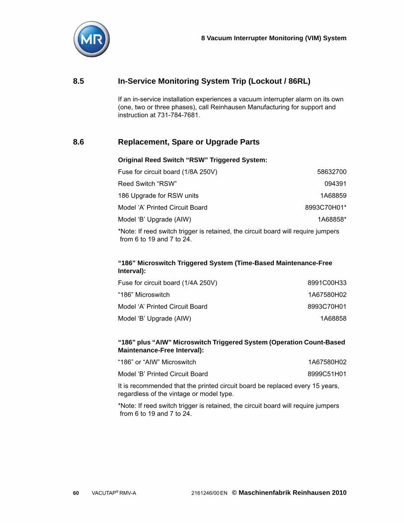
8.6 Replacement, Spare or Upgrade Parts
Original Reed Switch “RSW” Triggered System:
Fuse for circuit board (1/8A 250V) 58632700
Reed Switch “RSW” 094391
186 Upgrade for RSW units 1A68859
Model ‘A’ Printed Circuit Board 8993C70H01*
Model ‘B’ Upgrade (AIW) 1A68858*
*Note: If reed switch trigger is retained, the circuit board will require jumpers from 6 to 19 and 7 to 24.
“186” Microswitch Triggered System (Time-Based Maintenance-Free Interval):
Fuse for circuit board (1/4A 250V) 8991C00H33
“186” Microswitch 1A67580H02
Model ‘A’ Printed Circuit Board 8993C70H01
Model ‘B’ Upgrade (AIW) 1A68858
“186” plus “AIW” Microswitch Triggered System (Operation Count-Based Maintenance-Free Interval):
“186” or “AIW” Microswitch 1A67580H02
Model ‘B’ Printed Circuit Board 8999C51H01
It is recommended that the printed circuit board be replaced every 15 years, regardless of the vintage or model type.
*Note: If reed switch trigger is retained, the circuit board will require jumpers from 6 to 19 and 7 to 24.
8 Vacuum Interrupter Monitoring (VIM) System
© Maschinenfabrik Reinhausen 2010 2161246/00 EN VACUTAP® RMV-A 61
8.7 Monitoring System Vintage Identification
• Original Reed Switch “RSW” Triggered (Dedicated) Circuit
The circuit board for this version of the system has an enclosed signal transfor-mer which is blue in color and has relay covers that are transparent. This circuit board has one green and three red LEDs.
• “186” Microswitch or Reed Switch “RSW” Triggered (Universal) Circuit
The circuit board for this version of the system has an open signal transformer which is yellow in color and has relay covers that are transparent. This circuit board has one green and three red LEDs.
• “186” Microswitch Triggered (Dedicated) Circuit - Model ‘A’
The circuit board for this version of the system has an open signal transformer which is black in color and has relay covers that are also black. This circuit board has one green and three red LEDs.
• “186” plus “AIW” Microswitch Triggered (Dedicated) Circuit - Model ‘B’
The circuit board for this version of the system has an open signal transformer which is black in color and has relay covers that are also black. This circuit board has one green, three red, and three yellow LEDs.


9 Spare parts List
© Maschinenfabrik Reinhausen 2010 2161246/00 EN VACUTAP® RMV-A 63
9 Spare parts List
No. Quan-tity
Designation of Parts/Kits RM-item No.
9.1 1 Set Of “Hi-Pot Test” spare parts (Miscellaneous Hardware) for three phases
DA10092
9.2 3 Vacuum Interrupter Replacement kit (600 A and 1320 A) for one phase
DA10093
9.3 3 Bypass contact replacement kit for one phase DA10094
9.4 1 Bearing replacement kit for By-pass shaft DA10110
9.5 11
Front door gasketSide door gasket
9001C03H018991C34H01
9.6 11131
LTC Drive Shaft Flange AssemblyGear Box Drive Shaft Seal (large)Endplug (large)Gear Box Drive Shaft Seal (Small)Endplug (Small)
DA10095400 310401 828401 676401 827
9.7 11
1
Motor 208-240 V, 60 Hz, single phaseMotor with Thermo Switch (special design) 208-240V, 60 Hz, single phaseMotor 120V, 60 Hz, single phase
501154008990C54H01
8990C01H01
9.8 1 Motor Capacitor (Cylindrical) 585 546
9.9 1 Brake Capacitor Set 094 608
9.10 11
Brake Relay (4 Pole)Brake Relay (3 Pole)
8207C39H211A68742H01
9.11 1 Fuse for Electronic Box 8991C00H33
9.12 1 Test Set: Monitoring System Tripping Device 4D36273
9.13 1 Test Set: Vacuum Interupter Hi-Pot Device 4D36277
Table 5 Spare parts


10 Appendix
© Maschinenfabrik Reinhausen 2010 2161246/00 EN VACUTAP® RMV-A 65
10 Appendix
10.1 Operational Sequence Chart

10 Appendix
66 VACUTAP® RMV-A 2161246/00 EN © Maschinenfabrik Reinhausen 2010
10.2 Dehydrating Breather Assembly

10 Appendix
© Maschinenfabrik Reinhausen 2010 2161246/00 EN VACUTAP® RMV-A 67
10.3 Vacuum Interrupter Assembly

10 Appendix
68 VACUTAP® RMV-A 2161246/00 EN © Maschinenfabrik Reinhausen 2010
10.4 Parts Designation: Vacuum Interrupter Assembly

10 Appendix
© Maschinenfabrik Reinhausen 2010 2161246/00 EN VACUTAP® RMV-A 69
10.5 Bypass Switch Assembly

10 Appendix
70 VACUTAP® RMV-A 2161246/00 EN © Maschinenfabrik Reinhausen 2010
10.6 Parts Designation: Bypass Switch Assembly

10 Appendix
© Maschinenfabrik Reinhausen 2010 2161246/00 EN VACUTAP® RMV-A 71
10.7 Cam Switch Assembly

10 Appendix
72 VACUTAP® RMV-A 2161246/00 EN © Maschinenfabrik Reinhausen 2010
10.8 Parts Designation: Cam Switch Assembly
42
RMV-II LOAD TAP CHANGERCam Switch Assembly
Parts designationfor dwg 4D32299
Part No. Designation
011 618 CAM DISC
025 919 WASHER
043 126 MOUNTING PAD
049 010 WASHER
052 633 INSULATION
052 758 MOUNTING BOW
056 907 HOLDING SHEET
074 284 MOUNTING BRACKET
074 285 MOUNTING BRACKET
074 286 MOUNTING BRACKET
074 287 MOUNTING BRACKET
074 293 PLATE
076 156 DRIVE SHAFT
076 157 LIMIT SHAFT
076 158 PARALLEL SHAFT
076 159 PILOT SHAFT
076 160 TIE ROD
076 161 TIE ROD
076 163 SPUR GEAR
076 165 SPUR GEAR
076 169 MOUNTING BRACKET
076 179 POS. IND. MOUNTING
BRACKET
077 356 SPACER
077 403 POS. IND. SUPPORT
078 876 REDUCER BUSHING
094 068 PLATE ASSEMBLY
094 069 PLATE ASSEMBLY
094 070 SPUR GEAR ASSY
094 071 SPUR GEAR ASSY
094 072 SPUR GEAR ASSY
094 073 SPUR GEAR ASSY
094 074 SPUR GEAR ASSY
Part No. Designation
094 075 HNDCRNK LOCKOUT MTG PLATE
094 076 HNDCRNK PIPE SLEEVE
094 083 TIMING WHEEL
1A67533H03 SPRING
1A67580H01 MICROSWITCH
1A67580H02 MICROSWITCH 186 AND AIW ONLY
1A67582H01 INSULATION TUBING
200 887 SLIDING PAD
400 195 PIN SPNG DIN1481-4 x 24
400 441 SCR CHD DIN84-M 3 x 25-4.8
401 534 PIN SPNG DIN1481- 3 x 18
401 641 KEY DIN6885-A 4x 4 x 18
401 642 SCR SET DIN914-M 5 x 6
401 643 SCR SET DIN914-M 4 x 6
401 670 PIN SPNG DIN1481- 3 x 12
401 815 SCR SET DIN914-M 3 x 5
450 488 SCR HX DIN933-M 5 x 12-8.8
450 494 SCR HX DIN933-M 6 x 12-8.8
450 498 SCR HX DIN933-M 6 x 18-8.8
451 251 NUT HX DIN934-M 5-8
451 334 WSHR FL DIN125-B 6.4
451 385 WSHR LK DIN7980- 5
452 203 RING RTNG DIN471- 8 x 0.8
453 256 SCR HX DIN933-M 5 x 16-8.8
453 266 SCR HX DIN933-M 8 x 16-8.8
453 373 WSHR GL *-VSKD 6
453 973 NUT LK DIN980-V M 6-8
455 284 WSHR GL *-VSKD 8
584 836 POSITION INDICATOR
R0003700 RS3104-C M 3 x 8
R0003800 RS3104-C M 3 x 12
R0003900 RS3302-B 3.2MM
R0014200 RS3100-C .190-32 x .75
094 074 SPUR GEAR ASSY

10 Appendix
© Maschinenfabrik Reinhausen 2010 2161246/00 EN VACUTAP® RMV-A 73
10.9 Adjustment of Main Drive Shaft Coupling
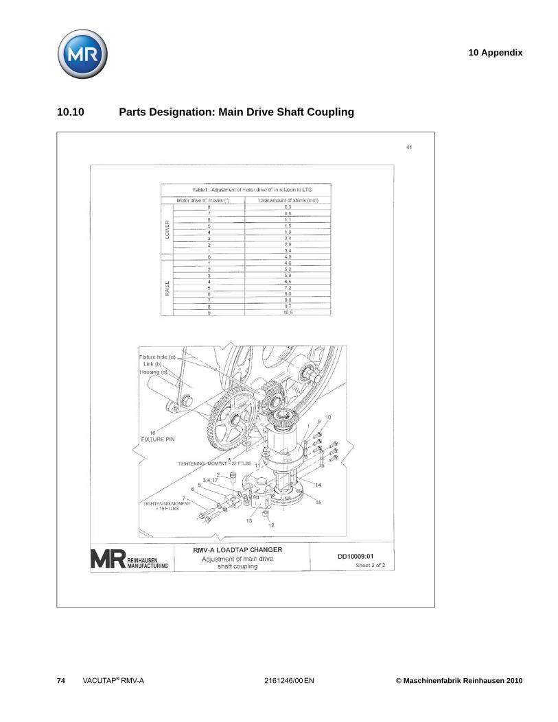
10 Appendix
74 VACUTAP® RMV-A 2161246/00 EN © Maschinenfabrik Reinhausen 2010
10.10 Parts Designation: Main Drive Shaft Coupling

10 Appendix
© Maschinenfabrik Reinhausen 2010 2161246/00 EN VACUTAP® RMV-A 75
10.11 Drive Mechanism, Ground Level Mounting

10 Appendix
76 VACUTAP® RMV-A 2161246/00 EN © Maschinenfabrik Reinhausen 2010
10.12 Parts Designation: Drive Mechanism, Ground Level Mounting

10 Appendix
© Maschinenfabrik Reinhausen 2010 2161246/00 EN VACUTAP® RMV-A 77
10.13 Drive Mechanism, Standard Mounting

10 Appendix
78 VACUTAP® RMV-A 2161246/00 EN © Maschinenfabrik Reinhausen 2010
10.14 Parts Designation: Drive Mechanism, Standard Mounting


2161246/00 EN • 05/10• F0209700• TL8001.03
©Maschinenfabrik Reinhausen GmbH Telefon: +49 (0)941 4090 0Falkensteinstraße 8 Telefax: +49 (0)941 4090 7001D - 93059 Regensburg E-Mail: [email protected]
www.reinhausen.com


![Series 35 PTO Compressor (301440) - JME Engineeringjmeengineering.com.au/images/pdf/SERIES35[1].pdfP/N: 301440: 19990317: pg 1 SERIES 35 PTO AIR COMPRESSOR OPERATORS, MAINTENANCE,](https://img.dokumen.tips/doc/110x75/60b10407dba29232bb53786a/series-35-pto-compressor-301440-jme-engin-1pdf-pn-301440-19990317-pg-1.jpg)