Embed Size (px)
Citation preview

INSTRUCTION MANUAL
INNOV-X SYSTEMS ALPHA SERIES™
X-RAY FLUORESCENCE SPECTROMETERS
August 2005 Version 2.1
Innov-X Systems, Inc. 10 Gill Street, Suite Q Woburn, MA 01801
Toll Free 866-446-6689 FAX 781-938-0128
Web-Site: www.innov-xsys.com 2003 Innov-X Systems, Inc. All rights reserved.

Copyright © Innov-X Systems, Inc. 2003 All rights reserved
No part of this publication may be reproduced, read or stored in a retrieval system, or transmitted, in any form or by any means, electronic, mechanical, by photocopying, recording or otherwise, without the prior permission of Innov-X Systems, Inc. THE INFORMATION IN THIS INSTRUCTION MANUAL IS FURNISHED “AS IS” WITHOUT WARRANTY AND FOR INFORMATIONAL PURPOSES ONLY. THIS DOCUMENT, IS SUBJECT TO CHANGE WITHOUT NOTICE, AND SHOULD NOT BE CONSTRUED AS A COMMITMENT BY INNOV-X SYSTEMS, INC. INNOV-X SYSTEMS, INC. ASSUMES NO LIABILITY FOR ANY ERRORS, INACCURACIES OR OMISSIONS THAT MAY APPEAR IN THIS MANUAL; NOR FOR INCIDENTAL OR CONSEQUENTIAL DAMAGES RESULTING FROM THE FURNISHING, PERFORMANCE, OR USE OF THIS MATERIAL. Please report any errors to Innov-X Systems, Inc.; in order that corrections can be made in future publications.
Innov-X Systems, Inc. 10 Gill Street, Suite Q Woburn, MA 01801
Toll Free 866-446-6689 FAX 781-938-0128 Web-Site: www.innov-xsys.com
2003 Innov-X Systems, Inc. All rights reserved.

TABLE OF CONTENTS Topic Page Chapter 1: INTRODUCTION
1.0 Inspecting the Analyzer 1-1 1.1 Components Included with the Analyzer 1-1 1.2 Quick Start Instructions 1-2 1.3 Introduction to XRF 1-3
Chapter 2: USAGE AND ASSEMBLY OF ACCESSORIES
2.0 Accessories 2-1 2.1 Analyzer Battery 2-1 2.2 Changing a Battery 2-1 2.3 Battery Charger 2-2 2.4 HP iPAQ Battery 2-3 2.5 Removing the iPAQ from Analyzer 2-3 2.6 Standardization Cap and/or Weld Analysis Mask 2-4 2.7 Testing Stand (optional accessory) 2-5
Chapter 3: RADIATION SAFETY
3.0 Important Safety Information 3-1 3.1 General Safety Precautions 3-1 3.2 Recommended Radiation Safety Training Components 3-2 3.3 Innov-X Safety Features 3-3 3.4 Performing a Test Following Appropriate Radiation Safety Procedures 3-3 3.5 Correct and Incorrect Instrument Usage 3-4 3.6 Radiation Warning Lights and Labeling 3-7
3.6.1 Main Power Switch and Indicator Light 3.6.2 Probe Light and Probe Label 3.6.3 Testing Light on Back of Analyzer 3.6.4 Label Behind iPAQ
3.7 Radiation Levels from Analyzer 3-8 3.8 Radiation Doses for Several Scenarios 3-9 3.9 Common Questions and Answers Regarding Radiation Safety 3-12 3.10 Safeguards and Emergency Response 3-13 3.11 Dosimeter Badges 3-14 3.12 Typical Registration Requirements 3-14
Chapter 4: OPERATION 4.0 Operation - General 4-1 4.1 Working with HP iPAQ Pocket PC® 4-1 4.2 Operation - Main Software Screens 4-1 4.2.1 Innov-X Main Menu 4.2.2 The Analysis Screen 4.2.3 The Results Screen 4.3 Passwords 4-3 4.4 Standardization 4-3 4.4.1 Standardization Procedure 4.4.2 Standardization Errors
4.4.3 Battery Replacement and Initialization/Standardization 4.5 Software Trigger Lock 4-7 4.6 Test Information—Label Input 4-8 4.6.1 Modifying the Test Info Template

4.6.2 Entering Test Information 4.6.3 Editing Test Info from the Results Screen
4.7 Exporting and Erasing Data 4-14 4.7.1 Installing ActiveSync 4.7.2 Exporting Results 4.7.3 Customizing Results Export 4.7.4 Exporting Spectra 4.7.5 Erasing Readings Chapter 5S: SOIL ANALYSIS
5.0 Check Standards 5S-1 5.1 Sample Presentation 5S-1 5.2 Testing in Soil Mode 5S-1 5.3 Soil Results Screen 5S-2 5.3.1 Results View Menu 5.3.2 Spectrum Screen 5.3.3 Test Info Screen 5.4 Soil Mode Options 5S-3 5.4.1 Set Testing Times 5.4.2 Soil Mode Test End Condition 5.5 LEAP Mode (Light Element Analysis Program) 5S-6 5.5.1 LEAP Settings 5.5.2 Testing Times
Appendix 1S: Troubleshooting Guide—Soil Analysis Appendix 2S Metals in Soil Analysis Using Field Portable X-Ray Fluorescence Appendix 3S: X-ray Registration Information General Appendices: Technical Specifications Certificate of Conformity—CE Innov-X Standard Warranty

Chapter 1 Introduction
1.0 INSPECTING YOUR INNOV-X ANALYZER Upon receipt: 1. Locate and remove the shipping papers and documentation from under the lid’s foam padding. 2. Remove the Innov-X Analyzer and all of the components from the protective carrying case and
identify each on the enclosed shipping list. 3. Connect the battery charger to an 110V-240V AC power source. Place one Li-ion battery on the
charger and charge it for at least 2 hours. Charge the second battery. 4. Charge the HP iPAQ using the attached AC adaptor for at least ½ hour. 5. Read and review the “Quick Start” section of the User’s Manual. Innov-X recommends that you read
the entire manual. 6. Install the fully charged battery into the analyzer. 7. Press the ON/OFF button on the back of the analyzer and the power button on the iPAQ. 8. Select Innov-X from the start menu located in the upper left hand corner of iPAQ screen. 9. Select the desired analysis mode (i.e., Analytical, FastID, Pass/Fail or Soil). The instrument will
undergo a one minute hardware initialization period. 10. Standardize the instrument with the 316 Stainless Steel mask. Standardize the instrument every 4
hours or as directed by the display. 11. Release the software trigger lock and analyze a sample of known composition, in order to verify the
correct operation of the analyzer. 12. Analyze samples of unknown composition.
1.1 COMPONENTS INCLUDED WITH THE ANALYZER Shown here are the various items which are included with the Innov-X portable XRF analyzer. Unless otherwise noted, all items are standard accessories.
Analyzer, with iPAQ attached.
Two, Li-ion batteries (one shown).
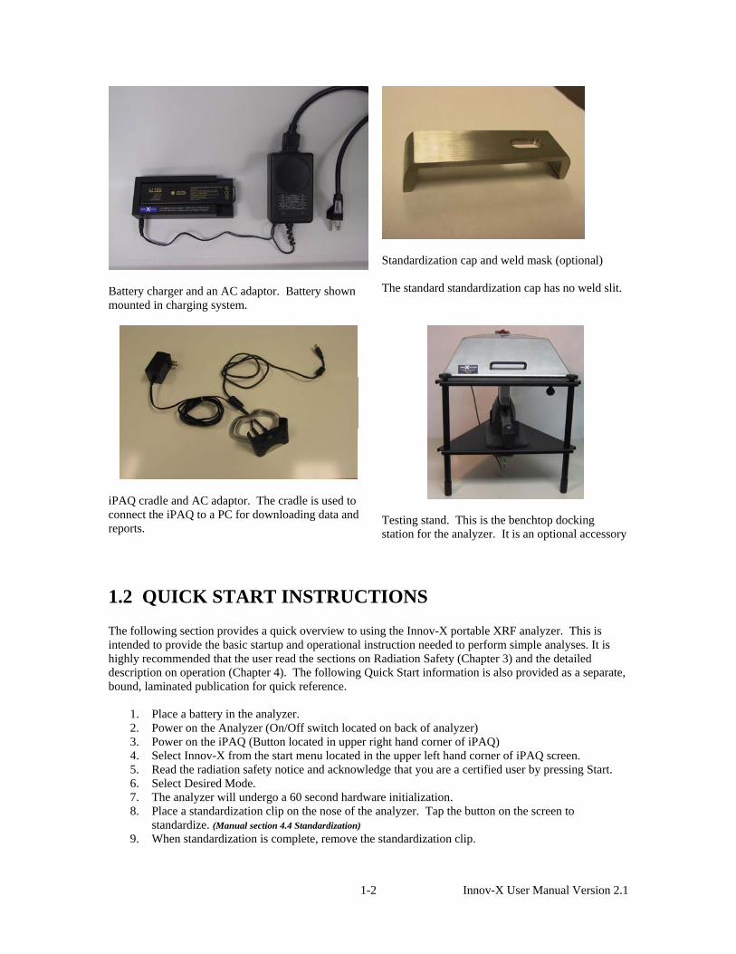
Battery charger and an AC adaptor. Battery shown mounted in charging system.
Standardization cap and weld mask (optional) The standard standardization cap has no weld slit.
iPAQ cradle and AC adaptor. The cradle is used to connect the iPAQ to a PC for downloading data and reports.
Testing stand. This is the benchtop docking station for the analyzer. It is an optional accessory
1.2 QUICK START INSTRUCTIONS The following section provides a quick overview to using the Innov-X portable XRF analyzer. This is intended to provide the basic startup and operational instruction needed to perform simple analyses. It is highly recommended that the user read the sections on Radiation Safety (Chapter 3) and the detailed description on operation (Chapter 4). The following Quick Start information is also provided as a separate, bound, laminated publication for quick reference.
1. Place a battery in the analyzer. 2. Power on the Analyzer (On/Off switch located on back of analyzer) 3. Power on the iPAQ (Button located in upper right hand corner of iPAQ) 4. Select Innov-X from the start menu located in the upper left hand corner of iPAQ screen. 5. Read the radiation safety notice and acknowledge that you are a certified user by pressing Start. 6. Select Desired Mode. 7. The analyzer will undergo a 60 second hardware initialization. 8. Place a standardization clip on the nose of the analyzer. Tap the button on the screen to
standardize. (Manual section 4.4 Standardization) 9. When standardization is complete, remove the standardization clip.
1-2 Innov-X User Manual Version 2.1

10. Release the software trigger lock by tapping the locked icon on the iPAQ screen and tapping yes in response to the software prompt.
11. Test standard to verify instrument performance. 12. Results will display on screen. Subsequent tests may be started from either the Results or
Analysis screens.
1.3 INTRODUCTION TO XRF: X-RAY FLUORESCENCE SPECTROMETRY OVERVIEW Basic Theory Although most commonly known for diagnostic use in the medical field, the use of x-rays forms the basis of many powerful analytical measurement techniques, including X-ray Fluorescence (XRF) Spectrometry. XRF Spectrometry is used to identify elements in a substance and quantify the amount of those elements present. An element is identified by its characteristic X-ray emission wavelength (λ) or energy (E). The amount of an element present is quantified by measuring the intensity of its characteristic line. XRF Spectrometry ultimately determines the elemental composition of a material. All atoms have a fixed number of electrons (negatively charged particles) arranged in orbitals around the nucleus. The number of electrons in a given atom is equal to the number of protons (positively charged particles) in the nucleus; and, the number of protons is indicated by the Atomic Number in the Periodic Table of Elements. Each Atomic Number is assigned an elemental name, such as Iron (Fe), with Atomic Number 26. Energy Dispersive (ED) XRF and Wavelength Dispersive (WD) XRF Spectrometry typically utilize activity in the first three electron orbitals, the K, L, and M lines, where K is closest to the nucleus. Each electron orbital corresponds to a specific and different energy level for a given element.
n
L
Primary X-ray
K
Emitted Electron
Secondary X-ray Photon - Fluorescence
Detector
X-ray Tube In XRF Spectrometry, high-energstrike the sample. The primary phthe innermost, K or L, orbitals. Wseek stability; therefore, an electrothe inner orbital. As the electron energy known as a secondary X-rray produced is characteristic of aphoton is determined by the differtransitions.
Photons L
y primary X-ray photons are emitted from a source (X-ray totons from the X-ray tube have enough energy to knock elehen this occurs, the atoms become ions, which are unstablen from an outer orbital, L or M, will move into the newly v
from the outer orbital moves into the inner orbital space, it eay photon. This phenomenon is called fluorescence. The se specific element. The energy (E) of the emitted fluorescenence in energies between the initial and final orbitals of the
1-3 Innov-X User Manu
K
Electro
ube) and ctrons out of . Electrons acant space at mits an condary X-
t X-ray individual
al Version 2.1
This is described by the formula
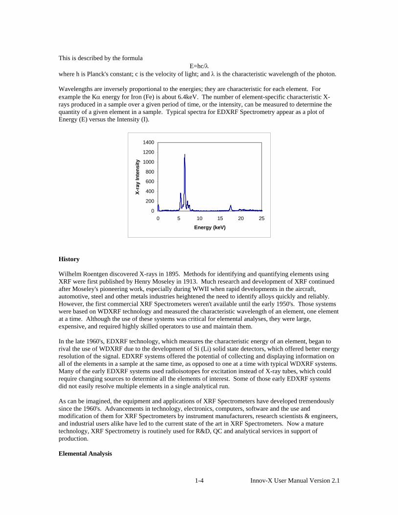
E=hc/λ where h is Planck's constant; c is the velocity of light; and λ is the characteristic wavelength of the photon. Wavelengths are inversely proportional to the energies; they are characteristic for each element. For example the Kα energy for Iron (Fe) is about 6.4keV. The number of element-specific characteristic X-rays produced in a sample over a given period of time, or the intensity, can be measured to determine the quantity of a given element in a sample. Typical spectra for EDXRF Spectrometry appear as a plot of Energy (E) versus the Intensity (I).
0
200
400
600
800
1000
1200
1400
0 5 10 15 20 25
Energy (keV)
X-ra
y In
tens
ity
History Wilhelm Roentgen discovered X-rays in 1895. Methods for identifying and quantifying elements using XRF were first published by Henry Moseley in 1913. Much research and development of XRF continued after Moseley's pioneering work, especially during WWII when rapid developments in the aircraft, automotive, steel and other metals industries heightened the need to identify alloys quickly and reliably. However, the first commercial XRF Spectrometers weren't available until the early 1950's. Those systems were based on WDXRF technology and measured the characteristic wavelength of an element, one element at a time. Although the use of these systems was critical for elemental analyses, they were large, expensive, and required highly skilled operators to use and maintain them. In the late 1960's, EDXRF technology, which measures the characteristic energy of an element, began to rival the use of WDXRF due to the development of Si (Li) solid state detectors, which offered better energy resolution of the signal. EDXRF systems offered the potential of collecting and displaying information on all of the elements in a sample at the same time, as opposed to one at a time with typical WDXRF systems. Many of the early EDXRF systems used radioisotopes for excitation instead of X-ray tubes, which could require changing sources to determine all the elements of interest. Some of those early EDXRF systems did not easily resolve multiple elements in a single analytical run. As can be imagined, the equipment and applications of XRF Spectrometers have developed tremendously since the 1960's. Advancements in technology, electronics, computers, software and the use and modification of them for XRF Spectrometers by instrument manufacturers, research scientists & engineers, and industrial users alike have led to the current state of the art in XRF Spectrometers. Now a mature technology, XRF Spectrometry is routinely used for R&D, QC and analytical services in support of production. Elemental Analysis
1-4 Innov-X User Manual Version 2.1

XRF Spectrometry is the choice of many analysts for elemental analysis when compared to the other techniques available. Wet chemistry instrument techniques for elemental analysis require destructive and time-consuming specimen preparation, often using concentrated acids or other hazardous materials. Not only is the sample destroyed, waste streams are generated during the analytical process that need to be disposed of, many of which are hazardous. These wet chemistry elemental analysis techniques often take twenty minutes to several hours for specimen preparation and analysis time. All of these factors lead to a relatively high cost per sample. However, if PPB and lower elemental concentrations are the primary measurement need, wet chemistry instrument elemental analysis techniques are necessary. XRF Spectrometry easily and quickly identifies and quantifies elements over a wide dynamic concentration range, from PPM levels up to virtually 100% by weight. XRF Spectrometry does not destroy the sample and requires little, if any, specimen preparation. It has a very fast overall sample turnaround time. These factors lead to a significant reduction in the per sample analytical cost when compared to other elemental analysis techniques. All elemental analysis techniques experience interferences, both chemical and physical in nature, and must be corrected or compensated for in order to achieve adequate analytical results. Most wet chemistry instrument techniques for elemental analysis suffer from interferences that are corrected for by both extensive and complex specimen preparation techniques, instrumentation advancements, and by mathematical corrections in the system's software. In XRF Spectrometry, the primary interference is from other specific elements in a substance that can influence (matrix effects) the analysis of the element(s) of interest. However, these interferences are well known and documented; and, instrumentation advancements and mathematical corrections in the system's software easily and quickly correct for them. In certain cases, the geometry of the sample can effect XRF analysis, but this is easily compensated for by grinding or polishing the sample, or by pressing a pellet or making glass beads. Quantitative analysis for XRF Spectrometry is typically performed using Empirical Methods (calibration curves using standards similar in property to the unknown) or Fundamental Parameters (FP). FP is frequently preferred because it allows elemental analysis to be performed with no standards or calibration curves. This enables the analyst to use the system immediately, without having to spend additional time setting up individual calibration curves for the various elements and materials of interest. The capabilities of modern computers allow the use of this no-standard mathematical analysis, FP, accompanied by stored libraries of known materials, to determine not only the elemental composition of an unknown material quickly and easily, but even to identify the unknown material itself. EDXRF Spectrometers EDXRF Spectrometer systems are mechanically very simple; essentially there are no moving parts. An EDXRF system typically has three major components: an excitation source, a spectrometer/detector, and a data collection/processing unit. The ease of use, rapid analysis time, lower initial purchase price and substantially lower long-term maintenance costs of EDXRF Spectrometers have led to having more systems in use today worldwide than WDXRF Spectrometer systems. Sample/Specimen EDXRF has been found most useful for scrap alloy sorting, forensic science, environmental analysis, archaeometry and a myriad of other elemental field-oriented analyses.
Spectrometer/Detector
Data Collection/ Processing Unit
Excitation Source
1-5 Innov-X User Manual Version 2.1

Handheld EDXRF Spectrometers for Field Analyses It is clear that a future trend for elemental analysis is in rapid site investigation using techniques that are fast, inexpensive, reliable, and long-term cost effective. There is a need for immediate decisions to be made during the delivery of materials, industrial processing, and in the field for positive materials identification or environmental site assessment and remediation. It is also clear that EDXRF Spectrometry is the most suitable elemental analysis technique available for field analysis due to its simplicity, speed, precision, accuracy, reliability, and overall cost effectiveness. Recent technological developments in cell phones, pocket PC's and other portable consumer electronics have led to the advancement of many high-performance, miniature components. X-ray equipment manufacturers began to take advantage of these developments in the late 1990's and developed Handheld EDXRF systems. An obvious advantage of Handheld EDXRF systems is that the analyzer is taken to the sample as opposed to bringing the sample to the analyzer and configuring it to fit in an analysis chamber. In addition to the per sample analytical cost savings, a key factor in using non-destructive EDXRF analysis, especially in the field, is the overall project cost savings due to improved and more timely decision making. The use of EDXRF for immediate positive materials identification or to guide an environmental site characterization will generally reduce the overall time required in the field due to the quick turnaround for the sample analysis; this invariably reduces the overall costs of analytical field work. Of course, Handheld EDXRF technology has continued to evolve in concert with portable consumer electronic developments. Just like the early Benchtop EDXRF systems, early Handheld EDXRF systems used radioisotopes for excitation. There are several practical problems with the use of radioactive isotopes for handheld systems. The source decays and loses its testing speed over time. In addition to the loss in analytical capabilities, the sources have to be replaced incurring a cost. The use of radioactive isotopes also requires licensing (state-to-state in the US) and a radioactive materials control program; they are difficult to ship and transport, as they require hazardous materials declarations and/or permits. Consequently, the newest and most exciting development in Handheld EDXRF technology is the use of battery operated, miniature X-ray tubes, which was pioneered by the staff at Innov-X Systems. Innov-X Systems Handheld EDXRF Spectrometers Innov-X Systems specializes in Handheld EDXRF technology with the most advanced miniature components available for X-ray Tube sources, detectors, and PC 's. Innov-X Systems Handheld EDXRF Spectrometers are ideally suited for field analysis of alloys, lead-based paint, environmental soils, filters, dust wipes, forensics, archaeometry, and a variety of other elemental analyses in the field or around the plant. Innov-X Systems EDXRF Spectrometers are affordable, easy to use, reliable, and overall cost effective. The Innov-X Systems Handheld EDXRF units incorporate state-of the art components including a battery operated miniature X-ray tube, a high-resolution silicon pin detector, high speed data acquisition circuitry, and a Compaq IPAQ Pocket PC® handheld computer for calculations, results and operator interface. Innov-X Systems EDXRF Spectrometers offer the following invaluable features:
• Portable • Battery operated, rechargeable • X-ray Tube-based (Ag or W anode, 10-40kV, 10-100uA) • Si PiN diode detector. • Integrated pocket PC • Pistol-shaped design for difficult testing locations and welds • Auto-compensation for irregular or small samples • Fundamental Parameters for no-standard analyses • Stored Grade Libraries for rapid Grade ID's • Stored Fingerprint Libraries for rapid material ID's
1-6 Innov-X User Manual Version 2.1

• Docking station available for use as standard benchtop unit • Results shown after a few seconds of testing time.
For more information on how to utilize your Innov-X Systems Handheld EDXRF Spectrometer optimally, please review this Instruction Manual or contact us directly.
1-7 Innov-X User Manual Version 2.1

Chapter 2. Usage and Assembly of Accessories 2.0 ACCESSORIES This chapter describes the various accessories that are provided with an Innov-X XRF analysis system. Included are:
Batteries Battery Charger iPAQ cradle and charger Testing Stand Assembly (not standard with all units) Standardization Clip or Standardization Clip/Welding mask.
2.1 ANALYZER BATTERY The Innov-X Systems XRF Analyzer is powered by a replaceable, rechargeable Lithium ion battery. In addition, the iPAQ has its own internal battery. Innov-X Systems Main Battery The Innov-X Analyzer uses a rechargeable Lithium Ion Smart Battery. A picture of the battery is shown in Fig. 2.1. Two batteries are included with each analyzer. The batteries are charged an external battery charger. Batteries typically function for 4 to 8 hours, depending on usage patterns. Heavier duty cycles deplete the battery more quickly. Therefore, users who do longer and more frequent tests will need to replace their batteries more often than users who take shorter or fewer tests. Replacement batteries can be purchased directly by calling Innov-X Systems at 781-938-5005. (P/N A003)
Figure 2.1. Li-ion
Battery for analyzer
Battery power indicators: There are two ways of determining the charge remaining on a battery: the LED indicator on the battery and the battery status icon on the analyzer screen. The battery icon, when tapped, will indicate the percent charge remaining on a battery inside the analyzer. Additionally, the battery icon will change from green to yellow when the battery gets low, indicating it has about 15 minutes left of charge. To use the battery LED, push the button below the indicator. The lighting will indicate the % of charge. If possible, try to use batteries with at least 50% of their full charge, according to the indicator. 2.2 CHANGING A BATTERY To change a battery, perform the following steps:
1. Hold the instrument by the handle, upside down, so the bottom of the instrument base is pointing upward. Please refer to Fig. 2.2.
2. Hold the instrument so that the nose is pointing away from the operator. 3. Open the battery door on the bottom of the handle. The batteries have a small tab attached for
ease of removal.
1 Innov-X User Manual Version 2.1 2-

4. Pull out the existing battery, and replace with a new battery. 5. Insert the charged battery into the analyzer such that the connectors on the top of the battery are
facing to the right. Note that the battery slot is keyed so that the battery can only be inserted one way.
Figure 2.2a. Instrument handle. Pull the rubber latch and lift door. Reach into opening and remove battery.
Figure 2.2b Insert new battery into opening.
2.3 BATTERY CHARGER The battery charger is shown in Fig. 2.3. It takes about 2 hours to completely charge a battery. The status of the charger is shown by two lights on the power adaptor. Table 2.1 lists the information conveyed by the lights.
Figure 2.3. Battery charger.
Left Light Right light Status
On Off Battery is charging On On Battery is 80% charged Off On Battery is completely charged
Blink Blink Error. Remove battery and replace on charger. If error persists, call Innov-X Systems Technical support.
Off Off No battery is on charger Table 2.1 Battery charger status lights
2 Innov-X User Manual Version 2.1 2-

2.4 HP IPAQ POCKET PC BATTERY The iPAQ has an internal rechargeable battery, which can be recharged by using the power adaptor that is included with the unit. This adaptor can be connected either to the iPAQ itself, or to the cradle. If it is connected to the cradle, and plugged in, the iPAQ will recharge whenever it is placed in the cradle. In addition, the iPAQ Battery will recharge whenever the iPAQ is mounted in an Innov-X analyzer which is powered, but not actively taking a test. The amber light on the top of the iPAQ will blink whenever the battery is charging. It will remain solid when the battery is completely charged. Since the iPAQ will be recharged whenever the Innov-X Systems Analyzer is in use, it may never be necessary to use the iPAQ power adaptor. However, care should be taken when the analyzer is not used for a period of several days, as the iPAQ uses some power even when it is powered off. It is therefore possible to completely discharge the battery simply by not using the iPAQ for several days, or by using it for several hours without recharging it. If you do not use your Innov-X Analyzer on a daily basis, or if you will have a down period of more than several days, it is recommended that you remove the iPAQ from the Analyzer when it is not in use and plug in the iPAQ to a power outlet to recharge it. This will ensure that your iPAQ is always charged and ready for use. You should also always plug in the power cord whenever the iPAQ is removed from the analyzer for data transfer. If you do allow the iPAQ battery to discharge significantly, either by allowing it to sit too long unused, or by using it for a period of time without it being connected to a power source, it may not be possible to operate your analyzer. If this happens, the Innov-X software will provide an error message indicating that the iPAQ battery is too low. Recharge the iPAQ for at least a half an hour before attempting another measurement. If the iPAQ battery is completely discharged, it will not be possible to turn on the iPAQ until it is recharged. A complete power failure will erase anything that is stored in the Main Memory of the iPAQ. All Innov-X program and data files are stored on the storage card, rather than in Main Memory, so you will not lose any data or have to reinstall the Innov-X software.
1. If the battery on the iPAQ is completely discharged, charge it for at least one half hour. 2. You will be required to follow the prompts on the iPAQ screen before you can use the iPAQ. This
procedure involves realigning the screen by tapping in several spots, and going through a quick tutorial.
3. The iPAQ will reinitialize the Innov-X Systems software. A message will appear indicating that this is going to happen. You must tap ok to initialize.
4. The software will open automatically; a message will appear indicating that several registries have been restored. Tap ok to dismiss this message.
5. Set the clock to the current time. Note, this is very important, as your data is indexed by date. If the date in the iPAQ is incorrect, you may not be able to locate your results. The instrument will not allow you to take a reading until the date has been changed.
a. From the Start Menu, tap Settings. b. Select the System tab, and tap clock. c. Set the proper date. Further details about this procedure can be found in the HP iPAQ
user’s manual.
2.5 REMOVING THE IPAQ FROM THE ANALYZER It is very important to properly remove the iPAQ Pocket PC from the analyzer to avoid damaging the connector on the back of the iPAQ. In order to remove the iPAQ, push the iPAQ retainer shown in Fig. 2.4 towards the front of the analyzer. Holding the retainer forward, grab the iPAQ from the sides, slide the iPAQ forward until it is clear of its
3 Innov-X User Manual Version 2.1 2-

connector, then tilt the front end up enough so it clears the front holder allowing the iPAQ to be lifted out of the instrument. Note: Never grab the iPAQ and twist it side-to-side to remove it from the analyzer. Always move the iPAQ retainer forward as instructed above, slide the iPAQ forward and remove from the analyzer.
Figure 2.4. Removing the iPAQ from the analyzer. 2.6 STANDARDIZATION CAP and/or WELD TESTING MASK All analyzers are supplied with either a standardization cap or a combination standardization cap welding mask. The standardization mask is the standard accessory. Welding masks can be purchased as an additional accessory, or in lieu of the standardization mask. Standardization Cap The cap clips on the front end of the analyzer and is used to standardize the system as described in Chapter 4. To attach the cap, snap it onto the nose of the analyzer over the Kapton window. Combination Standardization Cap/Welding Mask The standardization/welding mask is shown in Fig. 2.5. The cap clips onto the front end of the analyzer and is used to standardize the system as described in Chapter 4. To attach the cap, snap it onto the nose of the analyzer over the Kapton window. Be sure that when attaching the cap, that the solid end (as opposed to the end with the ¼” wide slit) is covering the window. To remove the mask, slide it off to either side. The opposite end of the standardization cap serves as a welding mask. This mask is used to shield the base metal from analysis, when analyzing a weld. It is important to use this mask since failure to do so will produce an alloy chemistry that is a mixture of the base metal and the actual weld. For best results:
a. Use the welding mask only for welds that are larger than the opening in the mask; b. Make solid contact between the surface of the mask and the material to test; c. Use the mask only in the Analytical Mode – not with the standard Fast ID library; d. Consider using longer test periods to compensate for the smaller testing area – especially
with more difficult separations. If it is desirable to use the welding mask in FastID mode, a user can create a special “Welding Mask Library.” Teach all relevant alloys with the welding mask is in position. Make sure these fingerprints are
4 Innov-X User Manual Version 2.1 2-

saved in library that contains ONLY fingerprints taught with a welding mask. When measuring a weld, make sure the “Weld” library is the only one selected. By creating a special finger print library using the welding mask, a user can get good results in the Fast ID Mode as well.
Figure 2.5 Standardization cap and welding mask. (Optional accessory)
The standard standardization cap does not have the welding slit. 2.7 TESTING STAND (optional accessory) The testing stand is designed as a docking station for the handheld analyzer. It can be used as a bench-top system, or to test small samples. A list of components and an assembled stand is shown in Figure 2.6: Components of the testing stand:
1 Three (3) short legs 2. Three (3) long legs 3. Lower Stand 4. Upper Stand 5. Four (4) knobs for top plate 6. Test stand cradle 7. Clip for cradle. 8. Adaptor cable (connects serial connector
on iPAQ cradle to auxiliary port on analyzer)
Figure 2.6. Assembled Testing Stand
Assembly of Testing Stand 1. Insert the three Short Legs through the holes in the Lower Stand by inserting the threaded screw through the holes. This will balance the Lower Stand on the table top. (Fig. 2.7).
Figure 2.7. Mounting Lower Stand onto Short Legs.
5 Innov-X User Manual Version 2.1 2-

2. Mount the three Long Legs onto the Lower Stand by inserting the threaded screws from the Short Legs into the holes on the Long Legs and turning until snug. Remove iPAQ from analyzer by following the instructions in Figure 2.4. Place the analyzer into the gap in the Lower Stand as shown. (Fig. 2.8).
Figure 2.8. Mounting Long Legs onto Lower Stand and inserting analyzer.
3. Mount the Upper Stand onto the Long Legs. The Upper Stand has holes for the screws at the end of each of the Long Legs. The Upper Stand will also fit snugly over the front end of the analyzer. Be sure that the Upper Stand is mounted so that all three screws are inserted through the holes, and the front end of the analyzer is flush with the top surface of the upper stand. (Fig. 2.9).
Figure 2.9. Mounting Upper Stand onto Testing Stand.
5. Put three knobs to secure testing stand onto analyzer. The iPAQ clip can be secured with any of the knobs. This clip grabs the base of the iPAQ cradle to hold the iPAQ securely in place. 6. Place the iPAQ in the cradle and connect it to the Auxiliary Port on the analyzer using the serial cable adaptor.
Figure 2.10. Connecting iPAQ to Auxiliary Port on analyzer.
6 Innov-X User Manual Version 2.1 2-

Chapter 3 Safety Information 3.0 IMPORTANT SAFETY INFORMATION THE XRF SHOULD NOT BE POINTED AT ANYONE OR ANY BODY PART, ENERGIZED OR DE-ENERGIZED! The safe and proper operation of the Innov-X XRF instruments is the highest priority. These instruments produce ionizing radiation and should ONLY be operated by individuals, who have been trained by Innov-X Systems, Inc. and received a manufacturer’s training certificate. Innov-X recommends that operators and companies implement a written Radiation Safety Program, with safety components specific to the site and application of use of the instrument. The Radiation Safety Program should be reviewed annually and revised appropriately by a competent individual. Innov-X analyzers must be used by trained operators, according to the instructions presented in this manual. Improper usage may circumvent safety protections and could potentially cause harm to the user. Pay attention to all warning labels and messages.
Important Notice for all Canadian Users:
Canadian Federal Regulations (Radiation Emitting Devices Act) require that all Canadian users must be certified according to NRC Standard CAN/CGSB-48.97/2-2000 in order to use this device.
For this certification contact: Natural Resources Canada, Manager Nondestructive Testing Certification, CANMET, 568 Booth St., Ottawa, ON, K1A 0G1; Tele: (613) 943-0583; Fax(613) 943-8297.
Users are advised to contact their appropriate federal/provincial./territorial radiation protection agency for applicable rules of operation.
The Innov-X analyzer is a very safe instrument when used according to manufacturer’s recommended safety procedures as detailed in this chapter. Radiation levels during testing are < 0.1 mR/hr on all surfaces of the analyzer except at or near the exit port for the radiation. This means that if an operator follows standard operating procedures, they will not obtain any detectable radiation dose above naturally occurring background radiation, on their hand while holding the analyzer, or on any area of their body. This chapter details specifics of the radiation levels. It covers both standard (safe) and un-safe methods of operation, it provides radiation emission information, and also provides dose estimates for unsafe operations. 3.1 GENERAL SAFETY PRECAUTIONS AND INFORMATION: Retain and follow all product safety and operating instructions. Observe all warnings on the product and in the operating instructions. To reduce the risk of bodily injury, electric shock, fire and damage to the equipment, observe the following precautions: Heed service markings. Except as explained in this documentation, do not service any Innov-X product yourself. Opening or removing covers may expose you to electric shock. Service needed on components inside these compartments should be done only by Innov-X Systems, INC. Damage requiring service:
• The power cord, plug or battery contacts for the battery charger are damaged.
3-1 Innov-X User Manual Version 2.1

• Liquid has been spilled or an object has fallen onto the instrument. • The instrument has been exposed to rain or water. • The instrument has been dropped or damaged. • There are noticeable signs of overheating. • The instrument does not operate normally when you follow operating instructions.
Safety Precautions: Use the correct external power source: Ensure that the voltage is appropriate (100V-240 V/ 50-60 Hz) for charging the battery packs. Do not overload an electrical outlet, power strip, or convenience receptacle. The overall load should not exceed 80% of the branch circuit rating. Use cables and power cords properly: Plug the battery charger into a grounded electrical outlet that is easily accessible at all times. Do not pull on cords and cables. When unplugging the cord form the electrical outlet, grasp and pull the cord by the plug. Handle battery packs properly; do not: disassemble, crush, puncture, short external contacts, dispose of in fire or water, or expose a battery pack to temperatures higher than 60 oC (140 oF).Do not attempt to open or service a battery pack.
WARNING: Danger of explosion if battery is incorrectly substituted. Replace only with Innov-X specified batteries. Used batteries may be returned to Innov-X Systems for disposal.
3.2 INNOV-X SYSTEMS – RECOMMENDED RADIATION SAFETY
TRAINING COMPONENTS Individual Companies and States have specific regulations and guidelines for the use of X-ray tube generated ionizing radiation. The purpose of the recommendations below is to provide generic guidance for an ALARA - best practice - approach to radiation safety. These recommendations do not replace the requirement to understand and comply with the specific policies of any state or organization. 1. Proper Usage. Never point the instrument at another person. Never point the instrument into the air
and perform a test. Never hold a sample in your hand and test that part of the sample. 2. Establish Controlled Areas. The location of storage and use should be of restricted access to limit
potential exposure to ionizing radiation. In use, the target should not be hand held and the area at least three paces beyond the target should be unoccupied.
3. Specific Controls. The instrument should be stored, in a locked case, or locked cabinets when not in use. When in use, it must remain in the direct control of a factory trained, certified operator.
4. Time - Distance - Shielding Policies. Operators should minimize the time around the energized instrument, maximize the distance from the instrument window, and shoot into high density materials whenever possible. Under no circumstances should the operator point the instrument at themselves or others.
5. Prevent Exposure to Ionizing Radiation. - All reasonable measures, including labeling, operator training and certification, and the concepts of time, distance, & shielding, should be implemented to limit radiation exposure to as low as reasonably achievable (ALARA).
6. Personal Monitoring. Radiation control regulations may require implementation of a radiation monitoring program, where each instrument operator wears a film badge or TLD detector for an initial period of 1 year to establish a baseline exposure record. Continuing radiation monitoring after this
3-2 Innov-X User Manual Version 2.1
period is recommended, but may be discontinued if accepted by radiation control regulators. Please refer to Sect. 3.10 for a list of providers of film badges.
3.3 INNOV-X SAFETY FEATURES The Innov-X analyzer is very safe when used correctly, however the analyzer does emit radiation through the analyzer window, and all precautions must be taken to reduce exposure to this radiation. In order to minimize the possibility of accidental exposure, the following safety features are standard in all Innov-X analyzers.
1. “Deadman” trigger. The trigger must be held for the duration of the test. This requires that the user consciously depress the trigger whenever x-rays are emitted, and ensures that the analyzer is attended at all times while x-rays are emitted.
Upon completion of safety training, an INNOV-X certified trainer may deactivate this feature upon request. The deactivation of the trigger is recommended only if long tests are required (such as for soil mode) and if the unit is used primarily by only 1 or 2 users who utilize it frequently, in a very controlled environment. In situations where multiple users are sharing the unit, it is recommended that the deadman trigger remain active. Note: Canadian Regulations require that the deadman trigger be used at all times. This feature will not be disabled for usage in Canada.
2. Software Trigger lock. Before using the trigger, the user must tap on a lock icon located in the lower right hand corner of the iPAQ screen. The user must then confirm that they wish to unlock the trigger. If the instrument is used continuously, the software trigger lock will remain off. If five minutes elapse between tests, the trigger will lock automatically.
3. Software Proximity sensor. The software requires that a sample be present in front of the
analyzing window. This prevents the accidental exposure of bystanders to an open beam. If the analyzer detects that a sample is not present, it will abort the test and shut off x-rays two seconds after the test is started.
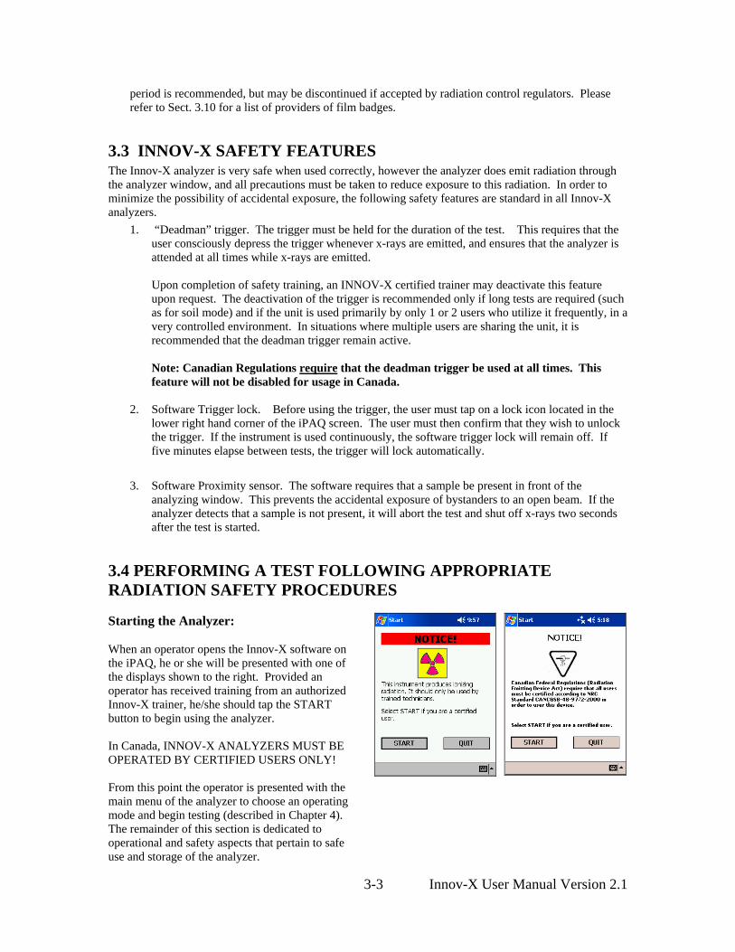
3.4 PERFORMING A TEST FOLLOWING APPROPRIATE RADIATION SAFETY PROCEDURES Starting the Analyzer: When an operator opens the Innov-X software on the iPAQ, he or she will be presented with one of the displays shown to the right. Provided an operator has received training from an authorized Innov-X trainer, he/she should tap the START button to begin using the analyzer. In Canada, INNOV-X ANALYZERS MUST BE OPERATED BY CERTIFIED USERS ONLY! From this point the operator is presented with the main menu of the analyzer to choose an operating mode and begin testing (described in Chapter 4). The remainder of this section is dedicated to operational and safety aspects that pertain to safe use and storage of the analyzer.
3-3 Innov-X User Manual Version 2.1

Starting a test using the trigger. When the trigger is depressed, the analyzer supplies power to the x-ray tube and opens the shutter to emit x-rays. If deadman trigger is enabled, the trigger must be depressed for the duration of the test. Releasing the trigger will close the shutter and immediately end the test. If deadman trigger is disabled, pulling the trigger once will start a test, pulling it again will stop it.
Figure 3.1 Handle of analyzer. Trigger is located at top of handle.
Starting a Test Using the “Start” Icon on the iPAQ Screen This feature is disabled in all units shipped. It will become active only if the “deadman” trigger is disabled. An operator may also begin a test by pressing the Start button on the touch screen, as shown at the right. The Start button, rather than the trigger, is generally used when the analyzer is docked into the testing stand. This Feature is not available in Canada. All tests must be started via the trigger.
3.5 CORRECT AND INCORRECT INSTRUMENT USAGE: The Innov-X XRF analyzer can be used in several different testing configurations. Safety guidelines are described for each configuration. Configuration 1: Usage as a Handheld Alloy Analyzer: In this configuration the analyzer is held in the hand, placed on various types of samples and a test is performed. Samples include pipes, valves, large pieces of scrap metal, basically any sample large enough to be tested in place, rather than held in the operator’s hand. Point the instrument at a metal sample such that no part of your body including hands and/or fingers is near the aperture of the analyzer where x-rays are emitted. Using the analyzer in this manner assures that the operator will not obtain a radiation dose to any body part or extremity in excess of naturally occurring background radiation. The radiation at any surface of the analyzer is < 0.1 mR/hr except at the exit port and the immediate area around the exit port. The user should take care that personnel are not located within 3’ (1 m) of the front end of the analyzer during testing, in the direction of the x-ray beam. Provided the analysis window is completely covered, there is virtually no radiation being emitted around the area of the sample. However, if a small component or curved surface is being analyzed, some radiation will be detectable.
3-4 Innov-X User Manual Version 2.1
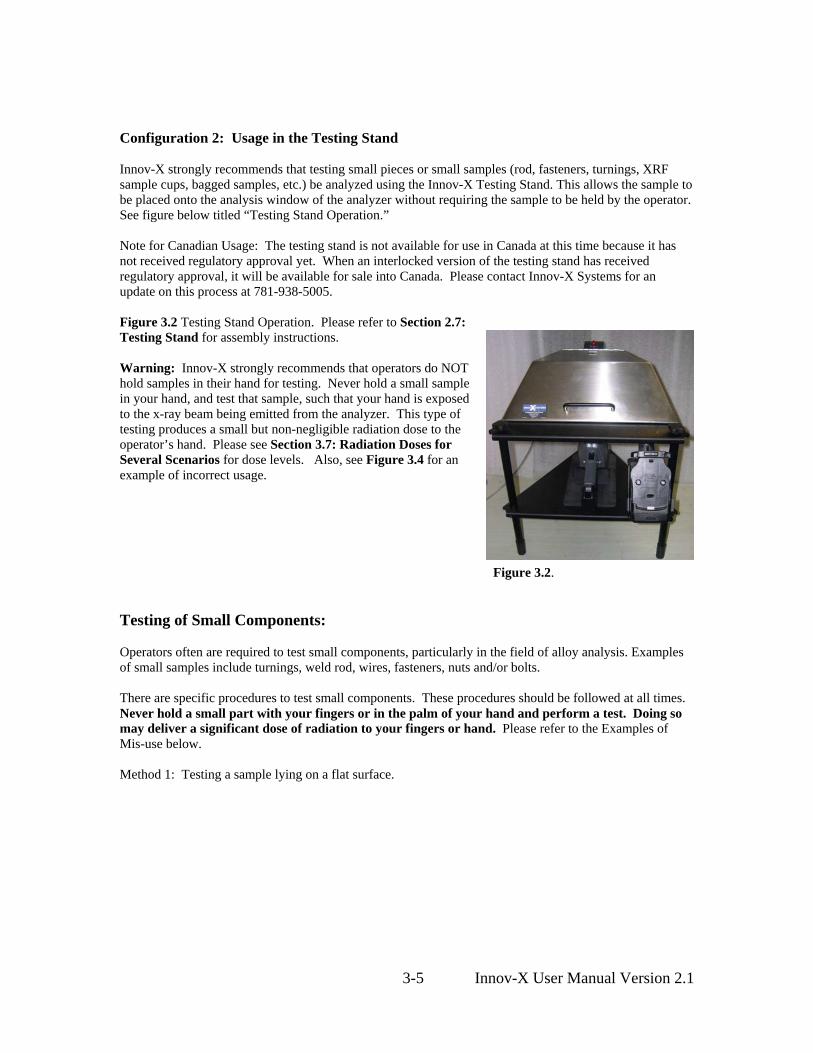
Configuration 2: Usage in the Testing Stand Innov-X strongly recommends that testing small pieces or small samples (rod, fasteners, turnings, XRF sample cups, bagged samples, etc.) be analyzed using the Innov-X Testing Stand. This allows the sample to be placed onto the analysis window of the analyzer without requiring the sample to be held by the operator. See figure below titled “Testing Stand Operation.” Note for Canadian Usage: The testing stand is not available for use in Canada at this time because it has not received regulatory approval yet. When an interlocked version of the testing stand has received regulatory approval, it will be available for sale into Canada. Please contact Innov-X Systems for an update on this process at 781-938-5005.
Figure 3.2 Testing Stand Operation. Please refer to Section 2.7: Testing Stand for assembly instructions. Warning: Innov-X strongly recommends that operators do NOT hold samples in their hand for testing. Never hold a small sample in your hand, and test that sample, such that your hand is exposed to the x-ray beam being emitted from the analyzer. This type of testing produces a small but non-negligible radiation dose to the operator’s hand. Please see Section 3.7: Radiation Doses for Several Scenarios for dose levels. Also, see Figure 3.4 for an example of incorrect usage.
Figure 3.2.
Testing of Small Components: Operators often are required to test small components, particularly in the field of alloy analysis. Examples of small samples include turnings, weld rod, wires, fasteners, nuts and/or bolts. There are specific procedures to test small components. These procedures should be followed at all times. Never hold a small part with your fingers or in the palm of your hand and perform a test. Doing so may deliver a significant dose of radiation to your fingers or hand. Please refer to the Examples of Mis-use below. Method 1: Testing a sample lying on a flat surface.
3-5 Innov-X User Manual Version 2.1

Figures 3.2.: Performing a testing for a sample lying on the surface of a table. This is a good way to test small samples, rather than holding them in your hand. To analyzer small sample:
• Place the sample onto a flat surface. • Place the window of the analyzer onto the sample and begin the test.
Safety Precautions: Do not test samples in this manner at a desk or table where the operator is sitting. If the desk is made of wood or another non-metallic material, some radiation will penetrate the desk and may provide exposure to legs or feet if the operator is sitting at the desk or table. Analytical Precautions: If the sample does not completely cover the window, be sure the surface used does not contain metals or even trace levels of metals, as this may affect the accuracy of the XRF result. The XRF may report the presence of additional metals in the surface material. For this type of testing, it is good to place the sample onto a piece of 1100series aluminum alloy and perform the analysis. The operator should disable the aluminum analysis capability (See Section 8.3.3 in the manual for instructions). Method 2: Use the testing stand as described above (see also Fig. 3.2).
Examples of Incorrect and Possible Unsafe Operation:
Improper Operation, DO NOT TEST SAMPLES LIKE THIS: Exposure to the operator’s hand/fingers will likely be minimal for this type of a testing, because the operator’s hands and fingers are not in the primary beam. However, Innov-X believes that this type of the analyzer sets a poor safety precedent in that any operation where the operator places their fingers or hands near the window should not be permitted.
Figure 3.3. Incorrect Usage. While the dose to the operator’s fingers/hand is negligible, testing this way sets a poor safety example for other operators, possibly encouraging other unsafe usage. Innov-X strongly recommends against this type of testing.
3-6 Innov-X User Manual Version 2.1
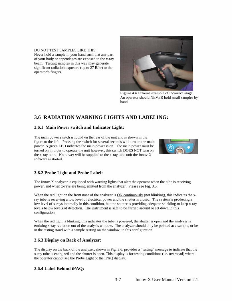
DO NOT TEST SAMPLES LIKE THIS: Never hold a sample in your hand such that any part of your body or appendages are exposed to the x-ray beam. Testing samples in this way may generate significant radiation exposure (up to 27 R/hr) to the operator’s fingers.
Figure 4.4 Extreme example of incorrect usage. An operator should NEVER hold small samples by hand
3.6 RADIATION WARNING LIGHTS AND LABELING: 3.6.1 Main Power switch and Indicator Light: The main power switch is found on the rear of the unit and is shown in the figure to the left. Pressing the switch for several seconds will turn on the main power. A green LED indicates the main power is on. The main power must be turned on in order to operate the unit however, this switch DOES NOT turn on the x-ray tube. No power will be supplied to the x-ray tube unit the Innov-X software is started.
3.6.2 Probe Light and Probe Label: The Innov-X analyzer is equipped with warning lights that alert the operator when the tube is receiving power, and when x-rays are being emitted from the analyzer. Please see Fig. 3.5. When the red light on the front nose of the analyzer is ON continuously (not blinking), this indicates the x-ray tube is receiving a low level of electrical power and the shutter is closed. The system is producing a low level of x-rays internally in this condition, but the shutter is providing adequate shielding to keep x-ray levels below levels of detection. The instrument is safe to be carried around or set down in this configuration. When the red light is blinking, this indicates the tube is powered, the shutter is open and the analyzer is emitting x-ray radiation out of the analysis window. The analyzer should only be pointed at a sample, or be in the testing stand with a sample resting on the window, in this configuration. 3.6.3 Display on Back of Analyzer:
The display on the back of the analyzer, shown in Fig. 3.6, provides a “testing” message to indicate that the x-ray tube is energized and the shutter is open. This display is for testing conditions (i.e. overhead) where the operator cannot see the Probe Light or the iPAQ display. 3.6.4 Label Behind iPAQ:
3-7 Innov-X User Manual Version 2.1

The analyzer also has a label just below the iPAQ indicating, as shown in Figure 3.7:
CAUTION: Radiation. This Equipment Produces Radiation When Energized.
This label is required by most regulatory agencies. The term “When Energized” refers to the condition where the tube is fully energized and the shutter is open. This condition is also indicated by the red blinking light on the probe.
Figure 3.5. Probe light and labeling. When the light is on continuously, the x-ray tube is receiving minimal power and it is producing a minimum level of x-rays. The shutter is also closed so there is no radiation exposure to the operator or bystanders.
Figure 3.6. Back light on analyzer.
Figure 3.7. Label behind iPAQ. Top version is used in Canada
3.7 RADIATION LEVELS FROM ANALYZER Two pictures of the analyzer are shown below. In the first picture, all the relevant components referenced in this radiation safety section are displayed and labeled. The second picture shows a close-up of the front end of the window. The four sides A, B, C and D are indicated on this picture because they are referenced in terms of radiation levels output by the analyzer. The measured radiation levels for standard operating conditions are shown in the figures and tables below. Standard operating conditions are tube voltage operating at 35 kV, tube current of 5 uA, and 2 mm aluminum filtration.
Figure 3.8 Innov-X Analyzer, Side View
3-8 Innov-X User Manual Version 2.1
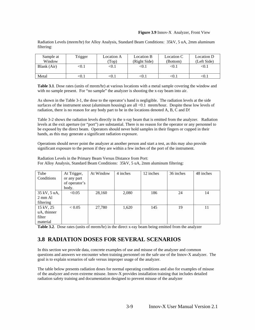
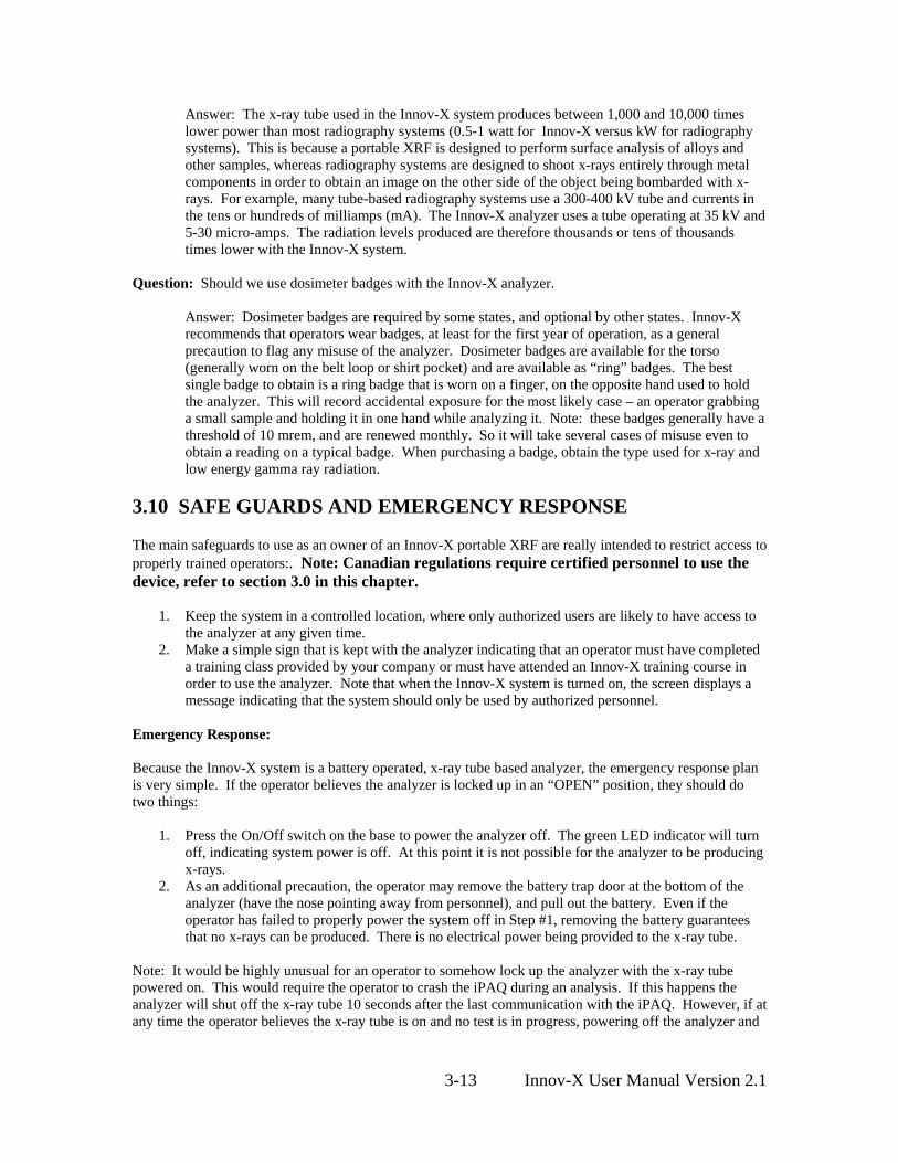
Figure 3.9 Innov-X Analyzer, Front View Radiation Levels (mrem/hr) for Alloy Analysis, Standard Beam Conditions: 35kV, 5 uA, 2mm aluminum filtering:
Sample at Window
Trigger Location A (Top)
Location B (Right Side)
Location C (Bottom)
Location D (Left Side)
Blank (Air) <0.1 <0.1 <0.1 <0.1 <0.1
Metal <0.1 <0.1 <0.1 <0.1 <0.1 Table 3.1. Dose rates (units of mrem/hr) at various locations with a metal sample covering the window and with no sample present. For “no sample” the analyzer is shooting the x-ray beam into air. As shown in the Table 3-1, the dose to the operator’s hand is negligible. The radiation levels at the side surfaces of the instrument snout (aluminum housing) are all <0.1 mrem/hour. Despite these low levels of radiation, there is no reason for any body part to be in the locations denoted A, B, C and D! Table 3-2 shows the radiation levels directly in the x-ray beam that is emitted from the analyzer. Radiation levels at the exit aperture (or “port”) are substantial. There is no reason for the operator or any personnel to be exposed by the direct beam. Operators should never hold samples in their fingers or cupped in their hands, as this may generate a significant radiation exposure. Operations should never point the analyzer at another person and start a test, as this may also provide significant exposure to the person if they are within a few inches of the port of the instrument. Radiation Levels in the Primary Beam Versus Distance from Port: For Alloy Analysis, Standard Beam Conditions: 35kV, 5 uA, 2mm aluminum filtering: Tube Conditions
At Trigger, or any part of operator’s body.
At Window 4 inches 12 inches 36 inches 48 inches
35 kV, 5 uA, 2 mm Al filtering
<0.05 28,160 2,080 186 24 14
15 kV, 25 uA, thinner filter material
< 0.05 27,780 1,620 145 19 11
Table 3.2. Dose rates (units of mrem/hr) in the direct x-ray beam being emitted from the analyzer 3.8 RADIATION DOSES FOR SEVERAL SCENARIOS In this section we provide data, concrete examples of use and misuse of the analyzer and common questions and answers we encounter when training personnel on the safe use of the Innov-X analyzer. The goal is to explain scenarios of safe versus improper usage of the analyzer. The table below presents radiation doses for normal operating conditions and also for examples of misuse of the analyzer and even extreme misuse. Innov-X provides installation training that includes detailed radiation safety training and documentation designed to prevent misuse of the analyzer
3-9 Innov-X User Manual Version 2.1

Example of Instrument Usage
Radiation Exposure and Comments
Normal Operation - Dose to Hand: User analyzes samples according to standard operating procedures described in this manual. Assumption: Operator using system with x-ray tube ON for 8 hours/day, 5 days/week, 50 weeks/year. (Practically constant usage).
Maximum exposure is to operator’s hand, at the trigger. Exposure is < 0.1 mrem/hr. Annual exposure to hand is then < 200 mrem (2mSv). US: Maximum exposure under OSHA regulations is 50,000 mrem annually. Thus continuous operation provides a dose that is at least 250 times lower than maximum allowed by OSHA. Canada: Maximum exposure under ICRP regulations is 500 mSv for radiation workers and 50 mSv for the general public. Thus continuous operation provides a dosage 250 times lower for a radiation worker and and 25 times lower for the general public.
Normal Operation – Dose to Torso: Analyzer is used under the same operating conditions described above.
Exposure to Torso is so low it cannot be measured. To be conservative we use the same figure as the trigger, <0.1 mrem hr. Annual exposure using operating conditions above is < 40 mrem. (0.4 mSv) Maximum allowed is 5,000 mrem under OSHA and 20 mSv under ICRP for radiation workers (1 mSv for general public).
For the x-ray energy emitted by portable XRF analyzers (10-60 keV region), the bone in the fingers will absorb radiation about 3-5 times more than soft tissue, so the bone would be at an elevated radiation risk compared to soft tissue. For this reason no person shall hold a test specimen in front of the window with the fingers in the direct beam, or direct the beam at any part of the human body. Reference: Health Physics 66(4):463-471;1994. Misuse Example 1: Operator holds samples in front of window with fingers, such that fingers are directly in the primary beam. Do not do this!.
For fingers at the port, in the primary beam, the maximum dose to the fingers is 28,160 mrem/hr. Assume an operator performs a 10 sec test (typical). The dose to the operator’s fingers or hand is 28,160 x (10/3600) = 78 mrem. If the operator did this 641 times/year they would exceed the allowable annual dose of 50,000 mrem to an extremity. In Canada, the maximum allowed dose is 500 mSv/year (Canada ICRP radiation worker) or 50 mSv/year (Canada ICRP general public). If the test time was 30 seconds instead of 10 seconds, the operator would receive a dose of 234 mrem for each exposure, and thus would exceed the annual safe limit of 50,000 mrem after 213 tests. Even though it is unlikely to make this mistake so many times in a year, do not even do it once. Take the extra time to test a sample on a surface or use a testing stand. Note: If the operator takes an average of only two shortcuts per week and places his/her fingers within the primary x-ray beam at the window, they will exceed the annual dose rate.
3-10 Innov-X User Manual Version 2.1

Misuse Example 2: Operator places analyzer against body and pulls the trigger to start a test. Analyzer tests to preset testing time (usually 10 seconds) unless operator pulls trigger again to stop test. This applies to analyzer being in contact with operator or with bystander.
Dose at exit of sampling window is 28,160 mrem/hr. Dose for a 10 second exposure with analyzer in contact with Torso: 78 mrem (.78 mSv). US: If an operator did this act 64 times in a year, the operator would exceed the annual safe dosage to the torso of 5,000 mrem/year. The maximum dose of 5,000 mrem/year is a whole body limit, which does not truly apply in this case because the x-ray beam size is small (about 2 cm2 area – 1.5 cm x 1 .3 cm – at the port). Applying correction factors for the beam size is complex and beyond the scope of this manual. The important point is that for proper operation there is no reason to ever exposure any part of the human body directly to the x-ray source. This example serves to provide estimated exposure in the event this occurs. If the testing time was 30 seconds instead of 10 seconds, thus the operator placed the port against his body or that of a bystander and performed a 30 second test, the dose would be 234 mrem. This is about the same as a mammogram. Repeating this gross mis-use 22 times would exceed the annual allowable limits. Canada: Radiation worker would have to repeat this example (234 mrem exposure) of gross misuse 8 times to achieve the ICRP level of 20 mSv. (general public 1.3 times to achieve limit of 1mSv)
Misuse Example 3: Operator manages to initiate a test for 10 seconds and exposes a bystander that is standing 12” away from analyzer port. What is exposure to bystander? Note: The proximity sensor would automatically shut down the x-ray tube after 2 seconds, so this is an extremely improbable occurrence. Note 2: Equations to scale these to other scenarios involving longer or shorter tests, and bystander being at distances other than 12” are provided at right.
Dose to bystander at 1 foot is 350 mrem/hr. For a 10 second exposure dose is 1 mrem. This is 5,000 times lower than the allowable dose to a worker in a year. This would have to happen 5,000 times to for that worker or bystander to obtain the maximum allowable dose. Formula for calculating other scenarios:
⎟⎠⎞
⎜⎝⎛
⎟⎠⎞
⎜⎝⎛
+=
1025.125.131
2 txD
mremDose
D = distance from port in inches T = testing time Example: Bystander is 3’ away from port for a 30 second test. In this case the dose is calculated as:
mremxmrDose 38.01030
25.13625.131
2
=⎟⎠⎞
⎜⎝⎛
⎟⎠⎞
⎜⎝⎛
+=
US OSHA: Maximum allowable level is 5,000 mrem assuming bystander’s torso is exposed. Thus, this misuse would have to occur 12,500 times in a year to the same bystander before that bystander achieved his maximum allowed dose. ICRP: 5000 times for rad worker, 250 for general public
3-11 Innov-X User Manual Version 2.1

Comparative: Radiation Doses from Typical Exposures to Ionizing Radiation Common medical and/or dental x-rays: 20-30 mrem each.
Mammogram: 100-200 mrem
Flying in a commercial jet coast to coast (6 hrs.): 1-2 mrem.
Daily exposure from background radiation: * depends on geographic location
0.3 to 0.5 mrem/day
Table 3.3 Radiation Doses from Typical Exposures to Ionizing Radiation From the above table, a single case of analyzer misuse, thus producing a one-time exposure of 70-250 mrem, is comparable with single-event common medical x-ray procedures such as an annual chest x-ray or mammogram, or 25-50 airline flights in a year, and thus is not considered harmful. Regular misuse, such as taking safety shortcuts twice weekly, produces radiation exposure that greatly exceeds these typical levels and should be avoided entirely. 3.9 COMMON QUESTIONS AND ANSWERS REGARDING RADIATION SAFETY Question: When I’m shooting a piece of pipe or valve on a rack or on a table top, is there any exposure to people standing in other locations, or standing several feet away from the analyzer?
Answer: Even a thin amount of metal sample (1-2 mm thickness) is enough to completely attenuate the x-ray beam emitted from the Innov-X analyzer. Shooting a piece of material that covers the sampling window on the analyzer will completely shield any bystanders from radiation exposure. However, good practice recommends that the area for at least 4-5 feet in front of the analyzer is clear of people.
Question: If I forgot to switch the safety on the trigger to “ON”, I pick up the analyzer and accidentally pull the trigger, is that dangerous to nearby personnel?
Answer: No, this example of misuse is not dangerous, but it may produce a non-negligible radiation exposure to nearby personnel. For an exposure to occur, the following things must happen. First, you must be holding the analyzer so that a bystander is actually standing in the x-ray beam being emitted. Just being near the analyzer is totally safe otherwise. Second, the bystander must be within 1-3 feet from the nose of the analyzer in addition to being in the beam path, to receive any appreciable dose. If all of these conditions are true, the dose received by a bystander is still extremely low. It ranges between 0.1 to 0.5 mrem depending on the exact location of the bystander. This dose is 10,000 to 50,000 times less than the allowed dose. Please see Misuse Example 4 in the table above.
Question: Do I need to create restricted areas where I am using the analyzer?
Answer: No, provided you are following normal operating procedures there is no reason to restrict access to an area where the analyzer is in use. The operator should take precautions to keep any personnel more than 3 feet away from the sampling window of the analyzer in the event of accidental misuse as detailed above. Should the operator also elect to test small components like weld rod as shown in Figure 3.3, the operator should also be sure that no personnel are standing within about 4-5 feet of the sampling window.
Question: How does the x-ray tube in the Innov-X system compare to a radiography system used for taking images of metal parts.
3-12 Innov-X User Manual Version 2.1
Answer: The x-ray tube used in the Innov-X system produces between 1,000 and 10,000 times lower power than most radiography systems (0.5-1 watt for Innov-X versus kW for radiography systems). This is because a portable XRF is designed to perform surface analysis of alloys and other samples, whereas radiography systems are designed to shoot x-rays entirely through metal components in order to obtain an image on the other side of the object being bombarded with x-rays. For example, many tube-based radiography systems use a 300-400 kV tube and currents in the tens or hundreds of milliamps (mA). The Innov-X analyzer uses a tube operating at 35 kV and 5-30 micro-amps. The radiation levels produced are therefore thousands or tens of thousands times lower with the Innov-X system.
Question: Should we use dosimeter badges with the Innov-X analyzer.
Answer: Dosimeter badges are required by some states, and optional by other states. Innov-X recommends that operators wear badges, at least for the first year of operation, as a general precaution to flag any misuse of the analyzer. Dosimeter badges are available for the torso (generally worn on the belt loop or shirt pocket) and are available as “ring” badges. The best single badge to obtain is a ring badge that is worn on a finger, on the opposite hand used to hold the analyzer. This will record accidental exposure for the most likely case – an operator grabbing a small sample and holding it in one hand while analyzing it. Note: these badges generally have a threshold of 10 mrem, and are renewed monthly. So it will take several cases of misuse even to obtain a reading on a typical badge. When purchasing a badge, obtain the type used for x-ray and low energy gamma ray radiation.
3.10 SAFE GUARDS AND EMERGENCY RESPONSE The main safeguards to use as an owner of an Innov-X portable XRF are really intended to restrict access to properly trained operators:. Note: Canadian regulations require certified personnel to use the device, refer to section 3.0 in this chapter.
1. Keep the system in a controlled location, where only authorized users are likely to have access to the analyzer at any given time.
2. Make a simple sign that is kept with the analyzer indicating that an operator must have completed a training class provided by your company or must have attended an Innov-X training course in order to use the analyzer. Note that when the Innov-X system is turned on, the screen displays a message indicating that the system should only be used by authorized personnel.
Emergency Response: Because the Innov-X system is a battery operated, x-ray tube based analyzer, the emergency response plan is very simple. If the operator believes the analyzer is locked up in an “OPEN” position, they should do two things:
1. Press the On/Off switch on the base to power the analyzer off. The green LED indicator will turn off, indicating system power is off. At this point it is not possible for the analyzer to be producing x-rays.
2. As an additional precaution, the operator may remove the battery trap door at the bottom of the analyzer (have the nose pointing away from personnel), and pull out the battery. Even if the operator has failed to properly power the system off in Step #1, removing the battery guarantees that no x-rays can be produced. There is no electrical power being provided to the x-ray tube.
Note: It would be highly unusual for an operator to somehow lock up the analyzer with the x-ray tube powered on. This would require the operator to crash the iPAQ during an analysis. If this happens the analyzer will shut off the x-ray tube 10 seconds after the last communication with the iPAQ. However, if at any time the operator believes the x-ray tube is on and no test is in progress, powering off the analyzer and
3-13 Innov-X User Manual Version 2.1
restarting will automatically shut down the x-ray tube and close the shutter. It will no longer be possible to produce x-rays at this point. 3.11 DOSIMETER BADGES Dosimeter badges are provided as a monthly service by several companies, listed in this section (see below). The badges are generally provided monthly, and the operator returns the previous month badges to the company for analysis. The operator receives a monthly report showing any personnel with readings higher than typical background radiation. Dosimeter badges are required by some states, and optional by other states. Innov-X recommends that operators wear badges, at least for the first year of operation, as a general precaution to flag any misuse of the analyzer. Dosimeter badges are available for the torso (generally worn on the belt loop or shirt pocket) and are available as “ring” badges. The best single badge to obtain is a ring badge that is worn on a finger, on the opposite hand used to hold the analyzer. This will record accidental exposure for the most likely case – an operator grabbing a small sample and holding it in one hand while analyzing it. Note: these badges generally have a threshold of 10 mrem, and are renewed monthly. So it will take several cases of misuse even to obtain a reading on a typical badge. When purchasing a badge, obtain the type used for x-ray and low energy gamma ray radiation. Dosimeter Companies: Here are two companies that provide badges as a regular service. There are certainly many more. Landauer Inc. Glenwood, IL 708-755-7000
AEIL Houston, TX 713-790-9719
3.12 TYPICAL REGISTRATION REQUIREMENTS Innov-X maintains a database of the registration requirements for every state, including sample registration forms. Most states require some form of registration, and generally they require the registration to be received within 30 days of receipt of the instrument. Some states require no registration, while a few require notification in advance. Please contact Innov-X for specific questions regarding the state where the instrument will be used, or for copies of registration forms. In general a company will have to provide the following information regarding the device:
1. Purpose of device. Generally this is “Analytical” or “Industrial.” Be sure to inform the state registration office that the device will NOT be used for radiography or for medical uses.
2. Radiation Safety Officer – Monitors training, safe use, and controls access to the instrument. 3. Authorized Users – Trained by Innov-X Factory Authorized Representatives in the safe and proper
use of the XRF. 4. Operating parameters of the analyzer – 35 kV, 5-30 micro-amps. 5. Type of system, either fixed, mobile or portable. Generally the correct choice is “Portable.” 6. User Training Specified – Indicate that only individuals receiving manufacturer training,
documented by a manufacturer’s training certificate will operate the instrument. 7. Personal Monitoring. This may be required by radiation control authorities. Many registration
forms will ask that you indicate whether or not you intend to perform dosimeter monitoring. 8. Copy of Registration & Manual at the Job Site
If you have any questions regarding the type of registration form or filling out the form, please contact Innov-X Systems. Many states may confuse a portable XRF system that uses a tube with medical or
3-14 Innov-X User Manual Version 2.1

industrial radiography systems. This is because of the relative newness of portable tube-based systems. In all likelihood, Innov-X personnel have experience providing the necessary documentation to the state in question, and can readily assist the customer in this process.
3-15 Innov-X User Manual Version 2.1

Chapter 4 Operation 4.0 OPERATION - GENERAL Power to the instrument is controlled by the ON/OFF button located at the rear of the analyzer. The green LED next to this button will illuminate when the analyzer power is on. The iPAQ operates on the Microsoft Windows CE ® operating system and is activated separately by the power button on the right top face, just over the display. The trigger is locked via the software. 4.1 WORKING WITH THE HP iPAQ Pocket PC® The Microsoft Windows CE ® operating system and Innov-X software provided on the iPAQ handheld computer are operated by user input through the touch screen. For comprehensive details on the iPAQ’s operation, please refer to the iPAQ reference materials included with your unit. General tips
• The Start Menu is found in the upper left corner of the iPAQ screen. This is used to launch all applications, including the Innov-X Systems Analyzer software.
• The instrument is designed as a “point and shoot” system that requires little, if any, entry of information for most operations. In the event the user modifies the grade library, enters testing information data, or performs other functions, it will be necessary to enter data via the virtual keyboard, which can be accessed by tapping the keyboard icon in the lower right corner. The iPAQ also includes character recognition software. This can be selected from the drop-down menu to the right of the keyboard icon.
• The File toolbar which will be used to Change Functions, Screens and Options is located at the bottom of the screen.
• It is possible to cut, copy, rename and delete files from within Windows File Explorer by selecting the file to be modified and holding the stylus on the screen for 2 seconds.
• Pressing buttons on the bottom of the iPAQ will perform various functions that are described in the iPAQ documentation. The button on the right hand size of the analyzer is the iPAQ task manager. Pressing this button will show all programs that are currently open. Open files can be closed from this menu. Simply hold the stylus on the file for a few seconds. The option to close the file will appear.
4.2 OPERATION - MAIN SOFTWARE SCREENS
The Innov-X Software consists of three main screens:
• Main Menu screen: Used to select the analysis mode, open the results screen, and change the administrator password.
• Analysis Screen: Used to change settings, edit libraries, and perform tests. • Results Screen: Displays results from current reading, allows scrolling back to previous test
results. Allows recorded data to be exported to a comma delimited file which is directly compatible with Microsoft Excel.
4.2.1 Innov-X Main Menu
The main menu below appears upon startup. The Main Menu allows you to choose an analysis mode, as well as perform certain administrative functions such as changing your login password. The modes which
4-1 Innov-X User Manual Version 2.1
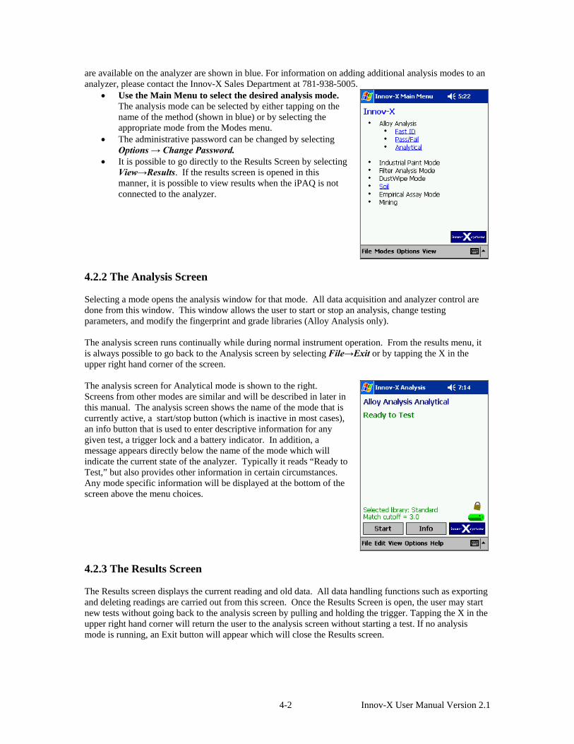
are available on the analyzer are shown in blue. For information on adding additional analysis modes to an analyzer, please contact the Innov-X Sales Department at 781-938-5005.
• Use the Main Menu to select the desired analysis mode. The analysis mode can be selected by either tapping on the name of the method (shown in blue) or by selecting the appropriate mode from the Modes menu.
• The administrative password can be changed by selecting Options → Change Password.
• It is possible to go directly to the Results Screen by selecting View→Results. If the results screen is opened in this manner, it is possible to view results when the iPAQ is not connected to the analyzer.
4.2.2 The Analysis Screen Selecting a mode opens the analysis window for that mode. All data acquisition and analyzer control are done from this window. This window allows the user to start or stop an analysis, change testing parameters, and modify the fingerprint and grade libraries (Alloy Analysis only). The analysis screen runs continually while during normal instrument operation. From the results menu, it is always possible to go back to the Analysis screen by selecting File→Exit or by tapping the X in the upper right hand corner of the screen. The analysis screen for Analytical mode is shown to the right. Screens from other modes are similar and will be described in later in this manual. The analysis screen shows the name of the mode that is currently active, a start/stop button (which is inactive in most cases), an info button that is used to enter descriptive information for any given test, a trigger lock and a battery indicator. In addition, a message appears directly below the name of the mode which will indicate the current state of the analyzer. Typically it reads “Ready to Test,” but also provides other information in certain circumstances. Any mode specific information will be displayed at the bottom of the screen above the menu choices.
4.2.3 The Results Screen The Results screen displays the current reading and old data. All data handling functions such as exporting and deleting readings are carried out from this screen. Once the Results Screen is open, the user may start new tests without going back to the analysis screen by pulling and holding the trigger. Tapping the X in the upper right hand corner will return the user to the analysis screen without starting a test. If no analysis mode is running, an Exit button will appear which will close the Results screen.
4-2 Innov-X User Manual Version 2.1

The Results screen is automatically shown at the completion of any analysis. It can also be accessed from the analysis screen for any mode or the Main Menu, by selecting View→Results. Once the Results screen has been opened, the information which is displayed can be changed by selecting options from the View menu. The various viewing options will be described in detail in later chapters.
4.3 PASSWORDS - ABOUT PASSWORD PROTECTION Certain functions such as adding and deleting fingerprints from the libraries, and Pass/Fail setup have been specified as Administrative Level Functions. These functions are described in detail in later sections of the manual. In order to use these functions, a password must be entered. The default password is set as the lowercase letter “z”. This password can be entered whenever the system prompts for a password. Changing the Administrator Password. The Administrator password may be changed at any time from the Innov-X Main Menu by choosing Options→Change Password. When the change password option is selected, this screen will appear.
If you are changing the password for the first time, enter the letter “z”; otherwise enter the current system password. Then, choose a password and enter it twice, once in the “New Password” box and again in the “Confirm Password” box. Passwords may be any combination of letters or numbers.
4.4 STANDARDIZATION 4.4.1 Standardization Procedure Before performing tests, it is necessary to standardize the instrument. This automated procedure involves collecting a spectrum on a known standard (Alloy 316) and comparing a variety of parameters to values stored when the instrument was calibrated at the factory. If there are any problems with the instrument, they will be indicated by an error message. The standardization procedure takes about 1 minute. Standardization must be done any time the analyzer hardware is initiated or restarted and must be repeated if the instrument is operating for more than 4 hours.
4-3 Innov-X User Manual Version 2.1

It is possible to re-standardize the instrument at any point while the software is running. Standardization is always initiated from the Analysis Screen of any Mode. If the analyzer is restarted, you will be required to standardize the instrument before performing any measurements. This is indicated by the message “Standardization Required. Please place a standardization clip over the analyzer window. Then tap here to standardize.” on the analysis screen
It is not possible to start a test before standardization. If the trigger is pulled before the standardization procedure is completed, a message box will appear. Press ok to acknowledge and clear the message.
To initiate the standardization procedure, snap the standardization piece on the front of the instrument. Verify that it completely covers the analyzer window. When using a standardization mask with a weld collimator, be sure that the solid portion of the mask covers the analyzer window. Tap the grey box in the center of the screen or select File→Standardize to begin.
4-4 Innov-X User Manual Version 2.1

When standardization is in progress, the red light on the top of the instrument will blink, indicating that the X-ray tube is energized and the shutter is open. In addition, a status bar will appear, tracking the progress of the measurement.
When standardization is complete, the message “Successful Standardization” will appear, along with the resolution of the instrument. Tap ok to acknowledge and clear the message. The instrument is ready for testing.
4.4.2 Standardization Errors The analyzer performs several diagnostic checks during the standardization process. If the standardization fails, the instrument will prompt the user regarding the next step. Several errors could occur while standardizing: “Wrong Standardization Material,” “Error in Resolution” or “Error in Count Rate”
4-5 Innov-X User Manual Version 2.1

After closing the Standardization Failed message, two additional screens will appear. The first is a picture of the spectrum generated during the standardization. The second is a summary comparing factory set values for resolution, count rate, and peak positions to values calculated during the standardization.
When standardization fails, verify that the standardization mask is in place, and attempt standardization again. To restandardize after a failure, tap the grey box in the center of the display, or choose File→Standardize. If you are using a weld collimator, make sure that the solid part of the mask is covering the window. If standardization fails again, exit the analysis screen and power off the instrument. Restart and restandardize. If the standardization fails a 3rd time, you will be prompted to perform a soft reset of the iPAQ. Selecting Yes on this screen will automatically soft reset the IPAQ. You should also power cycle the instrument. Restart and restandardize. If the standardization fails again, replace the battery in the instrument and attempt another standardization. If this fails, please contact the Innov-X Systems service center at 781-938-5005.
4-6 Innov-X User Manual Version 2.1

4.4.3 Battery Replacement and Initialization/Standardization
When the battery is too low to take a measurement, an error message will appear:
In order to continue testing, replace the battery immediately, and then tap “OK.” The analysis screen will remain open, and the instrument will reinitialize. This process will take 1 minute. It is not necessary to re-standardize, provided that less than 4 hours has elapsed since the last standardization and the battery swap is completed within 10 minutes. After re-initialization is completed, testing can continue. If the battery is not replaced, and cancel is selected, the Analysis screen will close. When the software is restarted, the instrument will go through a complete 1 minute initialization and will require standardization.
4.5 THE SOFTWARE TRIGGER LOCK Innov-X analyzers are equipped with a software trigger lock which prevents the trigger from being actuated unintentionally. The lock is released by tapping an icon on the iPAQ screen. Once the lock is released, it will remain unlocked for subsequent tests, until more than five minutes has elapsed between tests. At that point, the trigger lock will be activated and will need to be disabled before additional testing can commence.
Tap the lock icon located directly above the battery indicator.
Select yes to disable the trigger lock
The open lock icon indicates when the trigger is disabled.
4-7 Innov-X User Manual Version 2.1
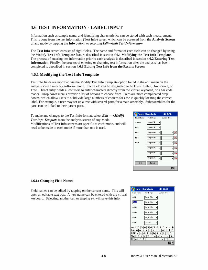
4.6 TEST INFORMATION - LABEL INPUT Information such as sample name, and identifying characteristics can be stored with each measurement. This is done from the test information (Test Info) screen which can be accessed from the Analysis Screen of any mode by tapping the Info button, or selecting Edit→Edit Test Information. The Test Info screen consists of eight fields. The name and format of each field can be changed by using the Modify Test Info Template feature described in section 4.6.1 Modifying the Test Info Template. The process of entering test information prior to each analysis is described in section 4.6.2 Entering Test Information. Finally, the process of entering or changing test information after the analysis has been completed is described in section 4.6.3 Editing Test Info from the Results Screen. 4.6.1 Modifying the Test Info Template Test Info fields are modified via the Modify Test Info Template option found in the edit menu on the analysis screen in every software mode. Each field can be designated to be Direct Entry, Drop-down, or Tree. Direct entry fields allow users to enter characters directly from the virtual keyboard, or a bar code reader. Drop down menus provide a list of options to choose from. Trees are more complicated drop-downs; which allow users to subdivide large numbers of choices for ease in quickly locating the correct label. For example, a user may set up a tree with several parts for a main assembly. Subassemblies for the parts can be linked to their parent parts.
To make any changes to the Test Info format, select Edit →Modify Test Info Template from the analysis screen of any Mode. Modifications of Test Info screens are specific to each mode, and will need to be made to each mode if more than one is used.
4.6.1a Changing Field Names
Field names can be edited by tapping on the current name. This will open an editable text box. A new name can be entered with the virtual keyboard. Selecting another cell or tapping ok will save this info.
4-8 Innov-X User Manual Version 2.1
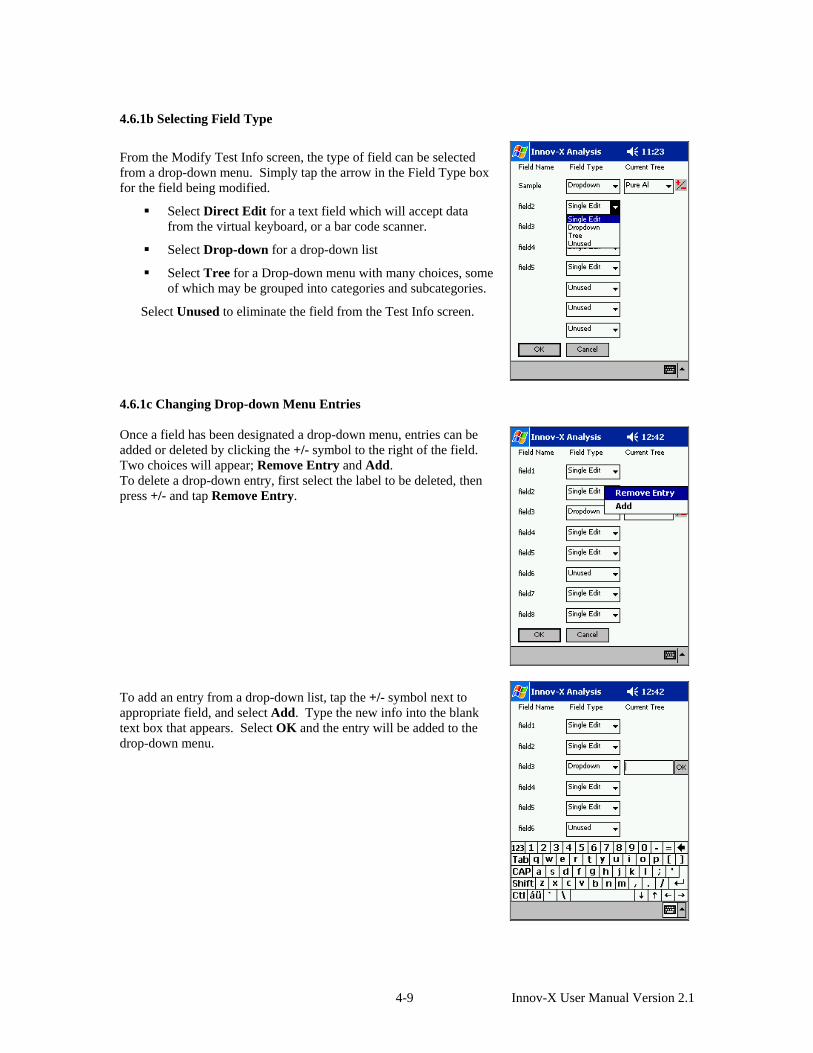
4.6.1b Selecting Field Type
From the Modify Test Info screen, the type of field can be selected from a drop-down menu. Simply tap the arrow in the Field Type box for the field being modified.
Select Direct Edit for a text field which will accept data from the virtual keyboard, or a bar code scanner.
Select Drop-down for a drop-down list
Select Tree for a Drop-down menu with many choices, some of which may be grouped into categories and subcategories.
Select Unused to eliminate the field from the Test Info screen.
4.6.1c Changing Drop-down Menu Entries Once a field has been designated a drop-down menu, entries can be added or deleted by clicking the +/- symbol to the right of the field. Two choices will appear; Remove Entry and Add. To delete a drop-down entry, first select the label to be deleted, then press +/- and tap Remove Entry.
To add an entry from a drop-down list, tap the +/- symbol next to appropriate field, and select Add. Type the new info into the blank text box that appears. Select OK and the entry will be added to the drop-down menu.
4-9 Innov-X User Manual Version 2.1

Repeat the process above to complete the complete drop-down list. If it is anticipated that a drop-down field will not be used for all samples, enter an empty field as a choice so you can choose to leave the field blank.
4.6.1d Changing Tree lists. Once a field has been designated a tree, modifications to the contents of the tree can be made by tapping the +/- symbol to the right of the tree.
All modifications to trees are made from the menu shown on the right. It is possible to add, edit, delete or rename trees. Select the appropriate choice from the menu to perform any of these functions. When you have finished creating/editing your tree, highlight it and select Done.
4-10 Innov-X User Manual Version 2.1

The following is an example of how a user might create a tree: A manufacturer of tubes and valves tests all parts to ensure that they’re made of the proper material. The company’s QC procedure involves labeling each test with the part number of the item. Rather than forcing operators to look through a long list of part numbers, a tree is created in order to subdivide the parts number into groups based on part type. The procedure for creating the tree is as follows: Select: Add New Tree:
Enter the Name of the Tree in the text box and select OK.
Tap Add to add the first item
4-11 Innov-X User Manual Version 2.1
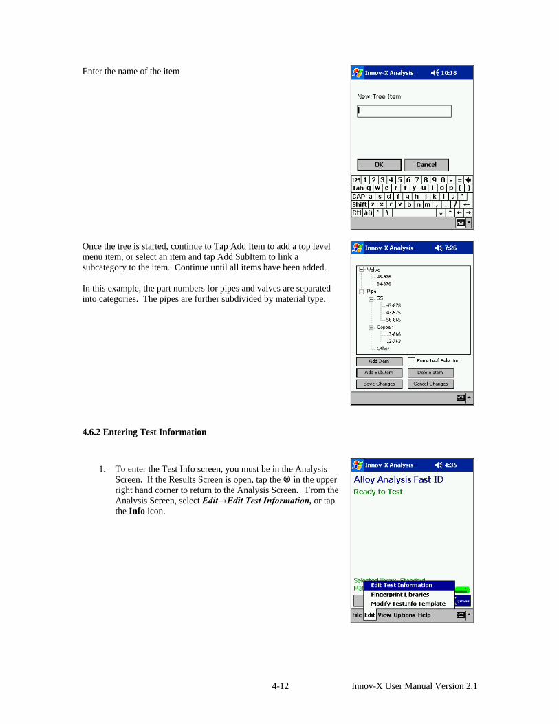
Enter the name of the item
Once the tree is started, continue to Tap Add Item to add a top level menu item, or select an item and tap Add SubItem to link a subcategory to the item. Continue until all items have been added. In this example, the part numbers for pipes and valves are separated into categories. The pipes are further subdivided by material type.
4.6.2 Entering Test Information
1. To enter the Test Info screen, you must be in the Analysis Screen. If the Results Screen is open, tap the in the upper right hand corner to return to the Analysis Screen. From the Analysis Screen, select Edit→Edit Test Information, or tap the Info icon.
4-12 Innov-X User Manual Version 2.1
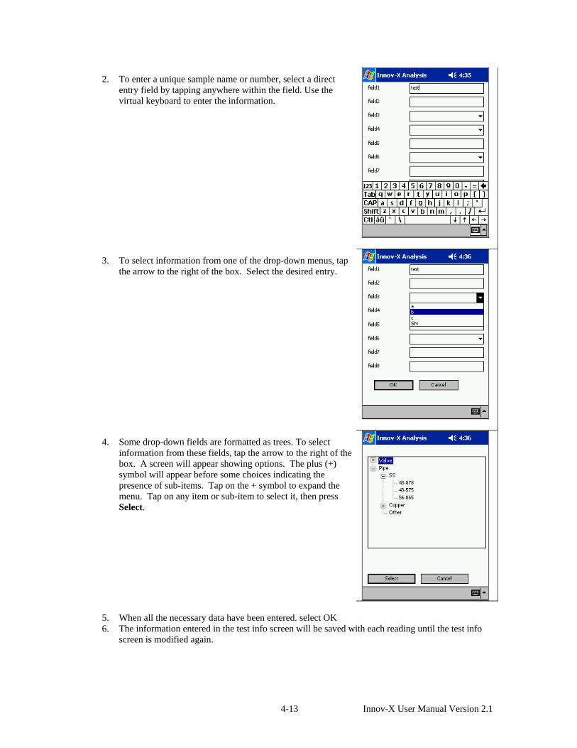
2. To enter a unique sample name or number, select a direct entry field by tapping anywhere within the field. Use the virtual keyboard to enter the information.
3. To select information from one of the drop-down menus, tap the arrow to the right of the box. Select the desired entry.
4. Some drop-down fields are formatted as trees. To select information from these fields, tap the arrow to the right of the box. A screen will appear showing options. The plus (+) symbol will appear before some choices indicating the presence of sub-items. Tap on the + symbol to expand the menu. Tap on any item or sub-item to select it, then press Select.
5. When all the necessary data have been entered. select OK 6. The information entered in the test info screen will be saved with each reading until the test info
screen is modified again.
4-13 Innov-X User Manual Version 2.1

4.6.3 Editing Test Info from the results screen Test information can be edited, or added to a test after its completion.
• From the results screen, scroll to the reading to be modified. • Select View →Test Info to see in the information which is
already stored. • Select Edit → Edit Test Info to bring up the editing menu.
You will then be presented with the same test information screen described in Section 4.5.2: Entering Test Information. 4.7 EXPORTING AND ERASING DATA Because the memory of the iPAQ is limited, you should periodically backup the data on your analyzer, and erase the memory. Depending on test volume, it is recommended that all data is erased on a weekly or monthly basis. 4.7.1 Installing ActiveSync In order to copy files between the iPAQ and a desktop PC, Microsoft Active Sync Software must be installed on the desktop PC. Innov-X strongly recommends that you download the latest version of ActiveSync from the internet. ActiveSync v3.7 may be downloaded from http://www.microsoft.com/windowsmobile/resources/downloads/pocketpc/activesync37.mspx If it is not possible to download the latest version, an ActiveSync CD (v3.5) was shipped with your analyzer. Check behind the foam in the instrument case. The iPAQ cradle should be hooked up to the USB port on the desktop computer before installing software. The Procedure for installing and setting up ActiveSync is as follows:
1. Insert the ActiveSync CD in your CD Drive. It will start automatically. The CD contains information about Getting Started with Your Pocket PC. This changes periodically, so it’s difficult to describe exactly what the screens will look like. Step through the screens until you see the option “Install ActiveSync.” Select this to start the installation process.
2. Follow the prompts on the screen. When given the choice, select “Run this program from its current location” and click OK.
3. Complete the install process. You will be required to restart your computer in order to complete the installation.
4. After restarting your computer, dock the iPAQ in the cradle. The iPAQ should automatically communicate with your computer. If it doesn’t, check the connections and try removing the iPAQ and reseating it. If that doesn’t work, try doing a soft reset on the iPAQ
5. When the computer communicates, you will be prompted to “Set Up a Partnership.” Select “Yes, with this computer”
4-14 Innov-X User Manual Version 2.1

6. Enter a name for your iPAQ and click next.
7. You will be prompted to “Select Synchronization Settings.” Select “Files” only. It is important to make sure that Files is the only item checked. Otherwise, the files such as address books and emails will be copied from the desktop computer to the iPAQ.
8. Step through the rest of the process.
9. A folder will automatically be created on the PC’s desktop with the name of the device entered in step 8 above. Results files saved on the iPAQ will automatically be synched and will be stored in this folder. Opening this folder and clicking on the name of the file will open the file in Excel.
10. After ActiveSync is set up correctly, copying results to a desktop computer will consist of
4-15 Innov-X User Manual Version 2.1
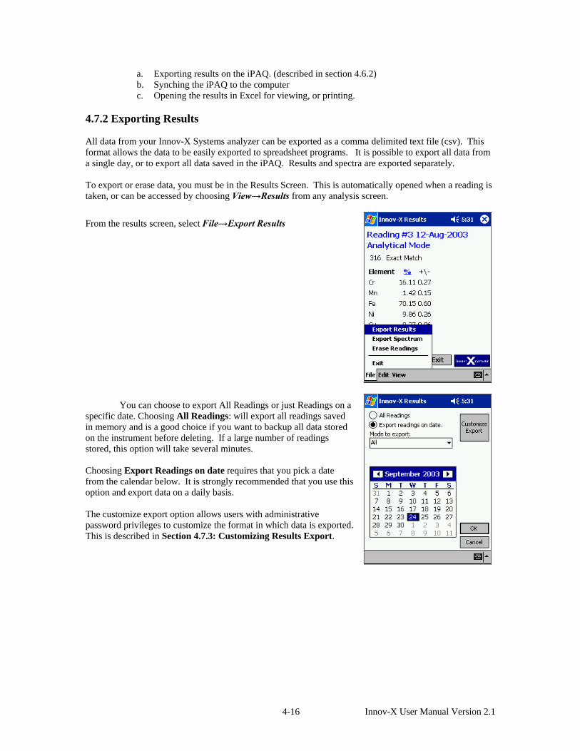
a. Exporting results on the iPAQ. (described in section 4.6.2) b. Synching the iPAQ to the computer c. Opening the results in Excel for viewing, or printing.
4.7.2 Exporting Results All data from your Innov-X Systems analyzer can be exported as a comma delimited text file (csv). This format allows the data to be easily exported to spreadsheet programs. It is possible to export all data from a single day, or to export all data saved in the iPAQ. Results and spectra are exported separately. To export or erase data, you must be in the Results Screen. This is automatically opened when a reading is taken, or can be accessed by choosing View→Results from any analysis screen.
From the results screen, select File→Export Results
You can choose to export All Readings or just Readings on a specific date. Choosing All Readings: will export all readings saved in memory and is a good choice if you want to backup all data stored on the instrument before deleting. If a large number of readings stored, this option will take several minutes. Choosing Export Readings on date requires that you pick a date from the calendar below. It is strongly recommended that you use this option and export data on a daily basis. The customize export option allows users with administrative password privileges to customize the format in which data is exported. This is described in Section 4.7.3: Customizing Results Export.
4-16 Innov-X User Manual Version 2.1

After choosing which readings to export, you may choose to export all data, or just data from a specific mode. Selecting the arrow to the right of the mode to export will open a drop-down menu. Select the mode for which you want to export data.
All standardization data are stored as results files. These data are automatically included in exported results files when the selected “Mode to export” is All. Additionally, it is possible to export only the standardization data by selecting Standardization as the “Mode to export.”
When the proper selections have been made, select OK. A Save As box will appear. Select the folder in which you want to save the data, and name the file. The file Type will always be Comma Separated Values. The recommended Location is Main memory and Folder is None. This will export files into the “My Documents” folder in the main Memory of the iPAQ. If you select a File Name which already exists, you will be asked if you want to replace the existing file. If you do, select Yes. Otherwise select No and choose another file name.
4-17 Innov-X User Manual Version 2.1

A status bar will indicate the progress of the export. It may take several minutes to export many readings. Daily downloading and weekly erasing of data simplifies and shortens this procedure.
When all readings are exported, a message will appear confirming the export. Tap ok to acknowledge and clear the reading.
4.7.3 Customizing Results Export All units come with a standard results export format which reports a variety of information relevant to a test. Users can select which fields are exported as well as modify the order. To modify exported results files, select File →Export Readings from the Results screen. Tap the Customize Export box. Enter the administrative level password when prompted.
4-18 Innov-X User Manual Version 2.1

Two columns appear on the screen; the column on the left lists fields which will NOT be exported, and the right-hand column lists fields which will be exported.
Fields can be moved from one column to another via the >> and << buttons located in the center of the screen
Exported field order can be changed by using the Up/Down buttons. Select a field and move it up or down as desired
Once all changes have been made, choose Specify Chemistry if changes need to be made to the list of exported elements.
In chemistry is not edited, select Save Changes to keep the modified settings, or Discard Changes to ignore any changes.
The Specify Chemistry screen resembles the previous screen. Move elements to the appropriate column, depending on whether or not an element should appear in exported files.
Select Include Errors to export the error associated with each measurement.
Select Display All to include all measured elements. This setting is recommended, as it will ensure that all data measured with the instrument is exported.
When all changes have been made, tap Save Changes or Discard changes, depending on whether the changes should be saved.
4-19 Innov-X User Manual Version 2.1

4.7.4 Exporting spectra Only one spectrum may be exported at a time. In the results screen, scroll to the reading for which you wish to export the spectrum, and Select File→Export Spectrum.
Choose the File name, and make sure that Comma Separated Values and Main Memory are selected. This will save the spectrum to the My Documents folder in the Main Memory of the iPAQ.
A message will appear indicating a successful export. Tap ok to acknowledge and clear the window.
4.7.5 Erasing readings It is possible to erase a single reading, a range of readings, all readings from a specific data, or all readings before a specific date.
4-20 Innov-X User Manual Version 2.1

In order to erase a single reading, the reading to be erased must displayed on the screen before selecting delete. If necessary scroll to the reading you wish to delete. In order to select a range of readings, you must have a reading open from the date you wish to delete the readings. If a reading from the desired date is not open, you may select View→Go to date, and select the appropriate date. The reading displayed in the results screen is not relevant if you want to delete all readings from a specific date, or all readings before a specific date .
From the results screen, select File→Erase Readings.
A message box will appear prompting you to enter your password. Enter your administrative level password and select OK.
A dialogue box will appear allowing a choice of which results to delete. Select the appropriate choice: • Selecting Delete current reading will delete the reading that is currently open. • Choosing Delete readings XX to XX will delete a range of readings from the date of the reading that is currently open. • Delete all readings on date deletes all readings from a specific day. • Delete readings before date deletes all readings taken prior to a specific day. If you select Delete all readings on date or Delete readings before date, you must specify a date from the calendar. The default date is the current date.
When you’ve selected the readings to delete, Click OK. You will be asked if you’re sure you want to proceed. If you want to proceed with the data erase, select Yes. Otherwise, click No.
4-21 Innov-X User Manual Version 2.1

A message will indicate the readings were successfully deleted. Tap ok to acknowledge and clear the message window.
4-22 Innov-X User Manual Version 2.1

Chapter 5 Soil Analysis The Innov-X analyzer can be used to analyze in situ (directly on the ground), bagged or prepared soil samples. A guide to Soil analysis using field portable X-ray fluorescence is found in the appendix. This document summarizes EPA Method 6200 which is the standard protocol for field screening. It also provides information on prepared sample testing. 5.0 CHECK STANDARDS It is recommended that a check standard is measured after each standardization, and periodically throughout the day. Innov-X provides several NIST certified standards for verification. The certified values for these samples are provided in the appendix. At least one standard should be measured for a minimum of 1 minute. Elemental concentrations for elements of interest plus or minus the error on the reading should be within 20% of the standard value. The Field screening guide in the appendix describes in more detail recommended quality assurance considerations. The standards provided with the XRF analyzer are contained in XRF sample cups with a Mylar window (through which the soil can be viewed) on one side, and a solid cap on the other side. Samples should be measured in the sample cup, through the Mylar window. The best way to measure a prepared sample is using the test stand. If this is not available, the sample may be placed on the ground, and the analyzer may be pointed downwards in full contact with the soil cup. Do not hold the soil cup in your hand while measuring. 5.1 SAMPLE PRESENTATION In situ testing: In situ testing is performed by pointing the analyzer at the ground. Any grass or large rocks should be cleared away and the analyzer should be held such that the front of the probe head is held flush to the ground. Since dirt can accumulate on the analyzer window, it is recommended that the window is wiped clean after each analysis. The window should also be checked to ensure it is not ripped or punctured. Instructions for replacing the window are found in the appendix. Bagged or prepared sample testing: It is strongly recommended that all prepared samples be analyzed in the testing stand. Samples should be placed on top of the testing stand, completely covering the window. Never hold prepared or bagged samples while testing, as this could expose the operator to the x-ray beam. Avoid measuring very thin samples, as this can affect results. Prepare samples cups to contain at least 0.5 inches of packed samples. When analyzing bagged samples, make sure that sufficient sample exists in the bag to completely cover the window with a sample thickness of a minimum of 0.5 inches. 5.2 TESTING IN SOIL MODE After the instrument has been standardized, testing can begin. Simply pull the trigger or press Start on the iPAQ screen to begin the test. The red warning light on the top of the instrument will blink, indicating X-rays are being emitted. The screen will display the words “Test in progress” and the time elapsed. The word “Testing” will blink on and off in the low right hand corner of the screen.
5S-1 Innov-X User Manual Version 2.1

After a minimum time has elapsed, intermediate results will be displayed on the screen. Until this minimum time has elapsed, the words “WAITING FOR DATA” will appear instead. This minimum time can be set by the user by selecting Options→Set Testing Times, which is described in Section 5.4: Soil Mode Options. Each line of the results display shows the name of an element, its calculated concentration and the error on the measurement. This error is the 1 sigma error on the counting statistics of the measurement. The error will decrease with increased testing time. Too many elements are measured in soil mode to display them at one time. However, is possible to use the scroll bar located to the right of the chemistry display to view other elements. The complete display shows detected elements first, listed in order of emission line energy, from lowest to highest. Following the detected elements are the elements which are below the detection limit of the instrument. These elements are shown as less than a calculated LOD. This LOD is defined as three times the error on the counting statistics of the measurement. When the measurement is complete the results screen will open, displaying the final results of the measurement.
5.3 SOIL RESULTS SCREEN 5.3.1 Results View Menu The standard Soil Mode results screen displays the concentration (in ppm) and error in measurement for detected elements, followed by the list of non-detected elements with the calculated limit of detection for each element for that test. If the display does not show soil chemistry results, change the display by selecting View→Results.
5S-2 Innov-X User Manual Version 2.1

The standard soil chemistry display can be modified by using the View Menu. As with all Innov-X analytical modes, it is possible to view spectra and Test Information. 5.3.2 Spectrum Screen This screen displays a plot of the x-ray fluorescence spectrum for an individual test, plotting the intensity on the y-axis versus the energy of the fluorescence x-rays on the x-axis. Tapping on the spectra will show the energy scale and counts rate at the selected point
It is possible to zoom in on certain areas of the graph by selecting one corner and drawing out the region Tapping the symbol in the upper right hand corner beneath the X will restore the graph to full scale.
5.3.3 Test Info Screen The test information screen shows any test information that was entered prior to the start of the test. Changes to that test information can be made by selecting Edit→Test Information. 5.4 SOIL MODE OPTIONS The length of tests in Soil Mode is user settable. Users may select a minimum testing time, and as well as choose from a variety of test end conditions. The options related to test time are contained in two menus: Options→Set Testing Times, and Options→Set Test End Condition. Set Testing Times contains minimum and maximum testing time information, while Set Test End Condition allows the user to select test end conditions.
5S-3 Innov-X User Manual Version 2.1

5.4.1 Set Testing Times To set the minimum and maximum test lengths, select Options→Set Testing Times
A screen appears prompting you to enter a Minimum and Maximum Testing times. Instruments equipped with the optional LEAP package will be able to set Light Element Testing times in this screen, as well.
The minimum testing time is the required time that must elapse before results can be calculated. Live Update results will not be displayed on the screen until the minimum has elapsed, likewise a test must complete the minimum time before any test end condition can be used. If a test is stopped before the minimum testing time has elapsed, the test will be aborted, and no results will be calculated. Maximum testing time is relevant only if “Maximum Testing Time” is selected from Set Test End Condition. This will automatically end the test at a preset testing time. Typically, the maximum testing time will be in excess of 30 seconds, and may be 1 or 2 minutes, depending on detection limits and desired precision. It should be noted, that all testing times in this section refer to “Real Time,” the time the measurement takes when timed on a normal clock. The time stored with each analytical result (accessible by selecting View→Test Information from the Results screen), refers to the test’s “Live Time”. This is the amount of time that the analyzer hardware was collecting spectra. Since there is some detector dead time associated with a measurement, the live time of a test will be slightly shorter than the preset “Real time”. 5.4.2 Soil Mode Test End Condition Four options exist for the test end criteria in soil mode. Depending on your application, you may choose to end the test manually, at a preset testing time, or when the uncertainty in the measurement is within a
5S-4 Innov-X User Manual Version 2.1

specified relative standard deviation of the reading. Additionally, you can set up an action level for a single element. As soon as the measuring statistics are good enough to ensure that that the reading is above, below or at the action level, the test will end automatically. This allows for very rapid tests for elements that are well above or below an action level. In all modes, pressing Stop, or pulling the trigger will end the test. If the minimum testing time has elapsed, results will be calculated. Otherwise the test will be aborted without calculating results. Changes to the test end condition are made by selecting Options→Set Test End Condition The currently selected end condition will be displayed at the bottom of the screen above the Start button on the Ready To Test screen.
Manual: This option allows you to look at the results which are being continually updated on the screen and determine when the results look satisfactory. The test will continue until the trigger is pulled, or Stop is tapped on the iPAQ screen. Results will be calculated if the testing time has exceeded the Minimum Test time which is set up in Options→Set Testing Times. In order to preserve battery life, the software will stop if the testing time exceeds 300 seconds, since there is little to no advantage to continuing a test beyond 300 seconds. To use Manual Test End Condition, simply choose Options→Set Test End Condition and select Manual. Press OK to return to the analysis screen.
Maximum Time: If Maximum Time is selected, the test will continue until the preset time is reached. This is useful if you wish to do a set of measurements with the same testing time. To choose to end test based on a maximum time, select Options→Set Test End Condition and select Maximum Time. Enter the desired testing time in the appropriate box. Tap OK to save your selections.
5S-5 Innov-X User Manual Version 2.1

Action Level: System ends test when result for target analyte including chosen precision level is above or below pre-set action level. To choose to end a test based on an Action Level, select Options→Set Test End Condition and select Action Level. Select a target analyte, specify an action level in ppm, and a confidence level. This confidence level refers to the number of sigma required for the precision. This should typically be set to 2. Tap OK to save your selections.
Relative Standard Deviation (RSD): When RSD is selected as a test end criteria, the system will end a test when the relative standard deviation on a target analyte reaches a pre-set level. This standard deviation is specified as a percentage of the reading. For example, if the measured value for an analyte was 1000 ppm, and the RSD was set to 10, the reading would stop when the error reached 100 ppm, or 10% of 1000. To choose to end a test based on a Relative Standard Deviation, select Options→Set Test End Condition and select Rel. Std. Dev (%). Select a target analyte and the desired Relative Standard Deviation. Tap OK to save your selections.
5.5 LEAP Mode (Light Element Analysis Program): This is a factory installed optional module. Instruments can be upgraded to LEAP capabilities. Please contact the Innov-X Systems Sales department for information and pricing. The LEAP module provides the lowest possible detection limits for elements lighter than iron. The standard LEAP package includes the elements Ti, Ba and Cr. Elements as low as Phosphorus can be detected with the Advanced LEAP package which includes a thin window detector. The standard x-ray beam conditions used by Innov-X environmental analyzers are designed to provide good excitation for a wide range of detected elements. However it is not possible to select one beam condition which provides the absolute best excitation conditions for all elements of interest. Elements such as Chromium produce lower energy x-rays then other elements analyzed. These lower energy x-rays are not as effectively excited by the standard conditions. LEAP works by changing the X-ray tube beam conditions to settings which are optimized for the detection of elements lighter than iron. Instruments are factory calibrated with the LEAP beam conditions for all applicable elements.
5S-6 Innov-X User Manual Version 2.1

5.5.1 LEAP Settings To activate LEAP, select Options→LEAP Settings from the Soil analysis screen. This brings up the menu shown below on the right.
Standard Test Only: The analyzer will provide analysis for the standard suite of elements. Light Element Analysis Only: The analyzer will provide analysis for elements in the LEAP suite (Typically Ti, Ba and Cr) Sequential Testing: When sequential testing is selected, all tests will start with an analysis of elements in the standard suite. If that test ends due to reaching the selected end condition of Maximum Test Time, Action Level, or RSD, then the analyzer will immediately begin a second test analyzing the LEAP suite of elements. At the conclusion of this test, the Results screen will open with two new entries. The first summarizes the standard test results, while the second summarizes the LEAP results. For safety reasons, the second test will not begin if the test ends due to user intervention (pulling the trigger or hitting Stop). In this case, the Results screen will open with only one reading. If Light Element Analysis Only is activated, the words “Light Element Analysis Mode” will appear above the currently selected End Condition. Instrument operation in this mode is identical to Standard (Non-LEAP) analysis. Tests can be started or stopped either by pulling the trigger, or by tapping the Start/Stop button on the iPAQ screen. The results screen for a test will show results for all elements analyzed with the LEAP mode.
Test in progress screen, LEAP Only, Live Updates on
Results Screen Showing LEAP
results
5S-7 Innov-X User Manual Version 2.1

If Sequential testing is selected, the words “Sequential – Current Test: Standard” will appear above the currently selected End Condition. When a test is started, the instrument will appear to operate in the same manner as a Standard test. However, if the test ends according to the specified end condition (excluding Manual), the results screen will not open. Instead, the timer will reset to 0, and the description of the current test will change from “Standard” to “LEAP”. The live update screen will begin to show analysis for all LEAP elements.
Test in progress screen,
Sequential. First Test – Standard Analysis.
Test in progress screen,
Sequential. Second Test – LEAP Analysis
5.5.2 Testing Times To set the minimum and maximum test lengths for LEAP analysis, select Options→Set Testing Times. The testing time screen includes an extra section labeled “Light Element Test” that is not found on non-LEAP systems. These are the minimum and maximum test lengths for any LEAP tests.
As with standard tests, the minimum testing time is the required time that must elapse before results can be calculated. Live Update results will not be displayed on the screen until the minimum has elapsed, likewise a test must complete the minimum time before any test end condition can be used. If a test is stopped before the minimum testing time has elapsed, the test will be aborted, and no results will be calculated.
Innov-X User Manual Version 1.3 5S-8

Appendix 1: Troubleshooting Guide—Soil Analysis
Problem Possible Solutions
Software won’t start:
Software will not start when the Innov-X Systems Icon is tapped.
The flash card or the iPAQ may not be correctly seated in the black external sleeve. Remove the flash card and press it firmly into its holder. Press the iPAQ down into the black sleeve.
Software won’t start:
Software doesn’t start when the Innov-X System icon is tapped; instead, the following error message occurs: “Cannot find ‘startup’ (or one of its components). Make sure the path and filename are correct and all the required libraries are available”
The flash card or the iPAQ may not be correctly seated in the black external sleeve. Remove the flash card and press it firmly into its holder. Press the iPAQ down into the black sleeve.
IPAQ locks up:
iPAQ screen “locks up” and doesn’t respond when screen is tapped or buttons are pressed
Remove the iPAQ from the analyzer and perform a soft reset by pressing the tip of the stylus into the small indentation found on the bottom of the iPAQ. If the iPAQ is lying flat on a table with the screen facing upwards, the reset button is found to the extreme right of the side containing the power plug and connector.
See Page 4 of the Compaq “Getting Started” manual for an illustration showing the location of the reset button.
Soil Appendix 1 Innov-X User Manual Version 2.1
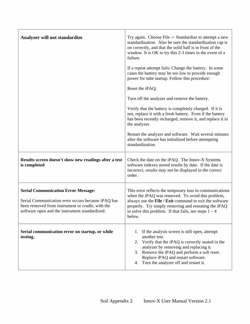
Analyzer will not standardize Try again. Choose File -> Standardize to attempt a new standardization. Also be sure the standardization cap is on correctly, and that the solid half is in front of the window. It is OK to try this 2-3 times in the event of a failure.
If a repeat attempt fails: Change the battery. In some cases the battery may be too low to provide enough power for tube startup. Follow this procedure:
Reset the iPAQ;
Turn off the analyzer and remove the battery.
Verify that the battery is completely charged. If it is not, replace it with a fresh battery. Even if the battery has been recently recharged, remove it, and replace it in the analyzer.
Restart the analyzer and software. Wait several minutes after the software has initialized before attempting standardization.
Results screen doesn’t show new readings after a test is completed
Check the date on the iPAQ. The Innov-X Systems software indexes stored results by date. If the date is incorrect, results may not be displayed in the correct order.
Serial Communication Error Message:
Serial Communication error occurs because iPAQ has been removed from instrument or cradle, with the software open and the instrument standardized.
This error reflects the temporary loss in communications when the iPAQ was removed. To avoid this problem, always use the File / Exit command to exit the software properly. Try simply removing and reseating the iPAQ to solve this problem. If that fails, see steps 1 – 4 below.
Serial communication error on startup, or while testing.
1. If the analysis screen is still open, attempt another test.
2. Verify that the iPAQ is correctly seated in the analyzer by removing and replacing it.
3. Remove the iPAQ and perform a soft reset. Replace iPAQ and restart software.
4. Turn the analyzer off and restart it.
Soil Appendix 2 Innov-X User Manual Version 2.1

Results take a very long time to display on the first test of the day.
There may be too many readings stored in memory. Erase readings from the results screen by selecting File → Delete Readings.
Trigger will not start test. Verify that the trigger lock is off. Reset the instrument. If this fails, call Innov-X Systems Technical Support at 781-938-5005.
Broken Kapton Window The window is designed as a barrier to dust and dirt. If it is damaged, it should be replaced.
To change the window:
Turn off the analyzer
Remove the screws holding the front plate in place.
Remove the old kapton and adhesive, replace with new kapton and replace front plate.
Important Note: It is very important to avoid getting dirt and sharp objects within the probe, due to the close proximity of the detector. Do not use the analyzer without a kapton window for any length of time. Also, be very careful when removing/replacing screws in face plate so as to not accidentally damage the detector. If the detector is damaged, the instrument will require factory service.
Results screen shows message “Error in calculation: No Results”
The soil mode calculation is only valid for “soil-like” samples which contain primarily light elements such as carbon, oxygen and silicon. If a dense, highly metallic sample is analyzed, the calculation fails.
Make sure the sample being analyzed is a soil sample, if it is and this message occurs repeatedly; call Innov-X technical support.
Soil Appendix 3 Innov-X User Manual Version 2.1
Appendix 2: Metals in Soil Analysis Using Field Portable X-ray Fluorescence A guideline to using portable XRF according to EPA Method 6200, basic overview of the technique of x-ray fluorescence (XRF), appropriate data quality assurance protocols and sample preparation steps for operators analyzing prepared soil samples. Prepared by: Innov-X Systems, Inc. January, 2003 Innov-X Systems 300 Wildwood Ave, Suite 210 Woburn, MA 01801 781-938-5005 781-938-0128 (fax) [email protected] www.innov-xsys.com
Soil Appendix 4 Innov-X User Manual Version 2.1

Section 1: Regulatory Status for Field Portable XRF
EPA Reference Method 6200 has been incorporated into SW486 under RCRA, and is now available for field portable XRF analysis of soils and sediments. Please call or email Innov-X Systems for a copy of Method 6200.
Method 6200: Field Portable XRF Spectrometry for the Determination of Elemental Concentrations in Soil and Sediment.
Features of this method:
1. It is a field screening method, for analysis of in-situ or bagged samples. 2. The method provides basic quality assurance methods, including calibration verification,
determination of instrument precision, accuracy and limit of detection. 3. The method recognizes the some XRF instruments do not require site-specific calibrations by
the operator, that is, the factory calibration provides appropriate data quality. 4. The method recommends that a minimum of 5-10% of samples tested by XRF be confirmed
by an outside laboratory using a total-digestion EPA analytical reference method.
The purpose of EPA Method 6200 is NOT to replace laboratory analysis. There are two primary sources of error in assessing a site for metal concentration: Analytical error and Sampling error. Analytical error is the error in the analysis of any one sample by whatever technique is used, for example XRF, ICP, or AA. Sampling error arises when too few samples are collected and tested. In this case an incomplete picture of the extent of metals contamination may be obtained. Although any one sample may be analyzed with very high analytical accuracy, measuring too few samples may result in contamination plumes being mis-judged in size, or depth into the soil. In extreme cases contamination may missed entirely.
EPA Method 6200 was developed to reduce Sampling Errors by increasing the number of samples measured. In general, a large number of screening-level measurements provide a better characterization of contamination than a small number of measurements produced by sample removal and analytical analysis. Portable XRF is an ideal tool to make a large quantity of measurements in a short period of time. A large number of in-situ samples provides detailed data on contamination profiles, depth (provided surface soil is moved aside), and approximate contamination levels. Portable XRF also can provide results with a high degree of analytical accuracy on any given sample. Please see Section 2 “Overview of Field Usage” for this discussion.
Soil Appendix 5 Innov-X User Manual Version 2.1

Section 2: Overview of Field Usage:
Field portable XRF is generally used in three ways to test for metals in soil:
In-situ soil testing: The XRF is placed directly onto the ground for soil testing. Operators remove any plant growth and foreign objects so that the analyzer probe is flush to the soil.
Bagged soil sample testing. A soil sample is collected in a thin plastic bag (i.e. a “Baggie”) and testing directly through the Baggie. Except for a few elements – namely Cr, V and Ba – testing through the thin plastic used for a plastic bag has little effect on the test result. Results for Cr, V and Ba will be lower by 20-30%.
Prepared soil sample testing. Prepared sample testing assures the operator of the maximum possible accuracy. Prepared sample tests require a sample to be collected, dried if necessary, sieved and ground into a powder. The prepared sample is then placed into a baggie or XRF cup for analysis. A complete Soil Preparation Guide is provided in Appendix 1.
All analytical methods require a uniform, homogenous sample for the best results. XRF is no different! The methods described in EPA Method 6200, namely In-situ and bagged sample testing, are considered field-screening methods. Although a field-screening method, in-situ testing is a valuable technique because it generates a great deal of data very quickly. Prepared soil samples generally offer the best accuracy, albeit with several minutes of sample preparation required per sample.
Figure 1. Use of a field portable XRF for in-situ soil testing.
Subsection 2-A: Data Quality Objectives.
The objectives of the testing generally determine the mixture of in-situ versus prepared sample testing. It is important to understand your data quality objectives (DQO) in order to determine the appropriate mix of field screening and prepared sample testing.
Soil Appendix 6 Innov-X User Manual Version 2.1

In-situ testing usually provides only screening-level data quality. This is because analytical testing always requires a uniform, homogeneous sample matrix. A laboratory achieves this by digesting the sample into a hot acid before analysis. Testing directly on the ground does not ensure uniformity is met. Preparing a sample provides a uniform sample and likely better analytical data quality, although several minutes of testing time is required.
Most portable XRF operators use a mixture of in-situ and prepared sample testing. Several examples are described below. The exact mixture of in-situ and prepared sample testing depends upon the goals of the soil testing. The examples below serve as guidelines. Please contact Innov-X (1-866-4 Innov-X or 866-446-6689) to discuss your specific testing requirements.
Example 1: Initial site investigation to provide detailed contamination data with efficient use of laboratory analysis costs. Problem: Site needs to be assessed for metals contamination. Little information is available about what metals are present, likely contamination levels or geographic profile of contamination. The goal of testing is to determine what metals are present at what levels, both in area and in depth into soil. Additionally, testing will locate possible contamination plumes and/or possible sources of contamination. Recommended Testing Plan: This example uses predominately in-situ testing. The analyst will perform in-situ testing, and gather samples into plastic bags for XRF analysis. A testing grid should be established in two or three dimensions, every several feet. XRF tests can be taken at each location or bagged samples can be collected from each location for later analysis. The in-situ data for each element analyzed may be plotted in a 2-dimensional grid (X, Y coordinates versus elemental concentration) to profile a site. These concentration profiles are ideal for showing contamination patterns, boundaries and plumes. Combining this data with historical use data from the site often allows the operator to deduce sources of contamination. Obtaining this level of geographic data with purely laboratory analysis would produce excessive analytical costs. Prepared sample analysis should also be done to confirm the regions where in-situ data indicates low or non-detected levels of metal contaminant. There is little need to prepare areas where in-situ testing indicates high concentration levels. Innov-X recommends the same procedure as EPA Method 6200. For locations where in-situ tested indicate low or non-detected concentrations, calculate the total number of in-situ tests, collect 5% of this number of tests from the various locations, and prepare these samples according to Appendix 1. Use these prepared samples to confirm the findings of the in-situ testing. Send a subset of these prepared samples to a laboratory for confirmatory results. Cost Justification. To adequately characterize a site may require 100-200 samples/acre to be sure the contaminated areas are firmly established. This work may be done with in-situ testing to generate laboratory savings of $5,000 - $10,000/acre depending upon the number of elements being analyzed. The cost reduction in off-site analysis often justifies the price of the XRF.
Example 2: Monitor remediation efforts and assure site meets clearance levels before contractors leave the site.
Goal: Minimize remediation costs by only treating contaminated soil, and obtain immediate verification that various site locations meet clearance objectives.
Soil Appendix 7 Innov-X User Manual Version 2.1
Recommended Testing Plan: This type of project uses a lot of both in-situ and prepared sample testing. Use in-situ testing to thoroughly delineate contamination regions in both area and depth. To determine depth profiles, test surface soil, remove at least 1-2 inches, and retest. Repeat this step as necessary to profile contamination depth to guide remediation activities. (XRF is a surface technique and only analysis the first few mm of soil sample). As part of clearance, collect several samples from “cleared” area. Prepare samples according to Appendix 1 and test with portable XRF.
If XRF indicates that concentration levels are in excess of clearance requirements, then continue remediation efforts.
If XRF indicates that concentration levels are below clearance requirements, then discontinue remediation efforts, and send a subset of the samples to an analytical laboratory to confirm results. Most operators safely assume that the cleanup requirements have been met for the elements in question, but await final analysis from the laboratory.
If XRF lists concentration levels as non-detected, but the detection level reported exceeds clearance requirements, send samples to a laboratory for final results.
Cost Justification: In-situ results are used to guide remediation efforts, in order to obtain maximum efficiency. Efficiency is produced because contamination boundaries are firmly established, thus avoiding remediation efforts with “clean” soil. Prepared sample testing is used to assure that clearance requirements are met on-site in near real-time (pending laboratory confirmation). Costs savings are generated by avoiding clearance failures. The contractors can leave the site earlier and will not be called back to the site for additional cleanup. Important Note: Never clear a site based solely on in-situ testing. Always use well-prepared samples to make a clearance decision.
Example 3: Minimize volume of hazardous waste for treatment or disposal.
Goal: For some cleanup projects, the cost of soil disposal in a hazardous waste landfill is much greater than disposal in a standard landfill. Testing soil samples with XRF may minimize the amount of “clean” soil that is inadvertently shipped to a hazardous-waste landfill.
Recommended Testing Plan: This example is almost entirely prepared sample testing. Representative samples are removed from the soil being hauled to landfill. Obtaining an accurate analysis of the samples is crucial for making a hazardous versus non-hazardous determination. For this reason, prepared sample testing is strongly recommended.
Important Note: These types of samples are subject to TCLP procedures for the landfill determination. In general, 20 times the XRF result should be less than the allowable limit for the metal in question. Please contact Innov-X Systems for more details on testing samples versus TCLP regulatory requirements.
Soil Appendix 8 Innov-X User Manual Version 2.1

Section 3: Quality Assurance. Quality assurance is detailed for both the proper use of the analyzer (which is also provided in Method 6200) and for verifying the data quality of in-situ testing. All operators should perform the QC procedure, regardless of their data quality objectives. Method 6200 has strict requirements about quality assurance. Additionally, Innov-X recommends that operators verify the data quality of in-situ test results, if they are using in-situ data to guide their reporting or remediation decisions. Procedures are listed below: 3.1: Proper verification of instrument operation These procedures are taken from EPA Method 6200 and updated to be specific to the Innov-X analyzer. Quality assurance here consists of testing known standards to verify calibration, as well as testing blank standards to determine limits of detection and to check for sample cross-contamination or instrument contamination. EPA Method 6200 provides a detailed procedure, which is provided here in abbreviated form. Components of instrument QC:
1. An energy calibration check sample at least twice daily 2. An instrument blank for every 20 environmental samples 3. A method blank for every 20 prepared samples 4. A calibration verification check sample for every 20 samples 5. A precision sample at least one per day. 6. A confirmatory sample for every 10 environmental samples
Energy Calibration Check: The Innov-X analyzer performs this automatically; this is the purpose of the standardization check when the analyzer is started. The software does not allow the analyzer to be used if the standardization is not completed. Instrument Blank: The operator should use the SiO2 (silicon dioxide) blank provided with the analyzer. The purpose of this test is to verify there is no contamination on the analyzer window or other component that is “seen” by the x-rays. Method 6200 recommends an instrument blank at least once per day, preferably every 20 samples. For either in-situ or prepared-sample testing, the operator should just test the SiO2 blank to be sure there are no reported contaminant metals. Method Blank: The purpose of the method blank is to verify that cross-contamination is not introduced into samples during the sample preparation process. Method 6200 recommends following the sample preparation procedures with clean SiO2 once very 20 prepared samples. This QC step is not required if the operator is not preparing samples. Calibration Verification: Innov-X provides NIST standard reference samples for calibration check by operator. The operator should perform a 2-minute test on a NIST standard. The difference between the XRF result for an element and the value of the standard should be 20% or less. Calibration Verification should be performed upon instrument startup and periodically during testing. Note: Innov-X recommends a calibration check every 4 hours. EPA Method 6200 recommends a calibration check every 20 samples NIST reference standards are generally applicable for Pb, As, Cr, Cu, Zn. Innov-X provides additional reference standards for other RCRA or Priority Pollutant metals including Cd, Se, Ag, Hg, Ag, Ba, Sn, Sb, and Ni.
Soil Appendix 9 Innov-X User Manual Version 2.1

Precision Verification: Quoting from EPA “A minimum of one precision sample should be run per day by conducting from 7 to 10 replicate measurements of the sample. The precision is assessed by calculating a relative standard deviation (RSD) of the replicate measurements for the analyte. The RSD values should be less than 20 percent for most analytes, except chromium, for which the value should be less than 30 percent. Confirmatory Sample: It is recommended that one confirmatory sample is run for every 10 samples collected. According to EPA Method 6200: “Confirmatory samples are collected from the same sample material that is analyzed on site, but are sent to an off-site laboratory for formal analysis. The purpose of a confirmatory sample is to judge the accuracy of the data obtained by analysis on site and to allow corrections, if necessary.” Important Notes about confirmatory samples: Innov-X always recommends that customers compare prepared-sample results to laboratory results. To do this, collect and prepare a sample following the protocols of Appendix 1. Take a subsample and submit to the laboratory for analysis. The single largest error in XRF analysis is lack of sample preparation. For the best comparison, always use prepared samples. 3.2: Determining data quality of in-situ testing: For operators relying extensively on in-situ testing, it is important to determine the data quality of this testing at a given site. This protocol is not intended for every sample, but rather for a small percentage of samples considered representative of the site. If the operator can demonstrate that quantitative data is achieved with little or no sample preparation, then the site characterization will be completed much more quickly but correctly. For example, an operator may be able to demonstrate that the XRF result changes considerably when samples are passed through a 2 mm sieve, but that XRF results do NOT change appreciably upon finer sieving. In this case the operator can conclude that good XRF data is achievable with only 2 mm sieving. Sieving only to this level requires far less time than a more robust sample preparation. A protocol to determine the appropriate level of sample preparation is the following:
1. Delineate a region of soil approximately 4" x 4". 2. Perform several in-situ tests in this area, or collect the top (approximately) quarter inch of
soil from this region, bag the soil, test through the bag. In either case, average the results. 3. If you did not bag the in-situ test sample, collect the top (approximately) quarter inch of
soil from this region and sieve through the 2 mm sieve provided. Otherwise sieve the bagged sample used for the in-situ test. Thoroughly mix the sieved sample, and place some of the sieved material into an XRF cup, and perform a test of this sample.
4. If the results of this prepared sample differ less than 20% with the average in-situ result, this indicates the soil in this region is reasonably homogeneous. The data quality in this case is probably at the semi-quantitative level, rather than just screening data.
5. If the results differ by more than 20%, this indicates the soil is not very homogeneous, and there are serious particle size effects affecting your in-situ measurements.
6. In this case, sieve the sample through the 250 ~m sieve. Mix this sample and place a sub-sample into an XRF cup for testing. If this result differs from the previous by less than 20% then this indicates that at a minimum the 2mm sieving is necessary to achieve higher data quality.
Soil Appendix 10 Innov-X User Manual Version 2.1

7. If this result differs by more than 20% from the sample sieved through 2 mm, then particle size effects are still affecting the XRF result. In this case samples should be sieved through 125 m to assure data quality at the quantitative level.
Section 4: Calibration for Innov-X Portable XRF
The Innov-X analyzer may run three different calibration methods, described below. In nearly all cases, customers use the Compton Normalization method. This method (recognized in EPA 6200) offers speed, ease of use, and generally good accuracy for concentration ranges from the ppm level up to 2-3% concentrations. As most field-testing is seeking to remediate or locate environmental contaminants, the upper limit of the calibration (2-3%) is generally not a limitation. If customers do require a calibration up to 100% concentration (i.e. a pure element) then Innov-X recommends they also include the Fundamental Parameters (FP) software module with the analyzer. The FP module may be added at time of purchase or as an upgrade at any later date.
Note: In general customers do not need to calibrate the Innov-X analyzer for soil testing. The analyzer is delivered with a factory calibration, generally based upon the Compton Normalization (CN) method. The CN method has been proven over the past several years to provide a robust calibration generally independent of site-specific soil matrix chemistry. The operator may calibrate the Innov-X system if desired, but calibration is not required to use the analyzer effectively. All customers should follow the QC procedure described in Section 3, which includes a check of the calibration.
The final model is the empirical calibration. In this case, customers run standards to generate calibration curves for various elements in specific soil matrices. Provided the sample is well-prepared, the empirical method generally yields the most accurate result. In our experience, the accuracy gains going from Compton Normalization to Empirical Mode are small and not worth the extra effort in setting up calibration curves. (The greatest source of error for in-field XRF analysis of soil is lack of adequate sample preparation, thus there is little gained in developing a sophisticated empirical calibration if the operator does to grind and homogenize the all measured samples). The empirical calibration module is an optional software package, available for an upgrade fee at the time of purchase, or as an upgrade at any later date.
Calibration Requirements:
The concentration of an element in a soil sample is well-described by the formula:
ii
i IiZM
kw
),(=
ki = calibration constant for element “i”
ωi = concentration of element “i” – the quantity being measured.
Ii = measured x-ray intensity from element “i”
M(Z,I) = Soil matrix value
Soil Appendix 11 Innov-X User Manual Version 2.1
The factory calibration determines the value of the calibration constants ki for each element, and a typical value M(Z,I). The calibration method – either CN, fundamental parameters, or empirical – performs the necessary corrections to the value M(Z,I) that are important for the site-specific soil chemistry. The XRF analyzer uses the measured intensity of each element’s fluorescence from the sample, and the calibration data, to produce elemental concentrations. Compton Normalization: The Compton Normalization method calibration consists of the analysis of a single, well-characterized standard, such as an SRM or SSCS. The standard data are normalized to the Compton peak. The Compton peak is produced from incoherent backscattering of X-ray radiation from the excitation source and is present in the spectrum of every sample. The matrix affects the way in which source radiation is scattered off the samples. This scatter is directly related to the intensity of the Compton peak. For that reason, normalizing to the Compton peak can reduce problems with matrix effects that vary among samples. Compton normalization is similar to the use of internal standards in analysis for organic analytes. Fundamental Parameters Calibration: The fundamental parameters (FP) calibration is a "standardless" calibration. Rather than establishing a unit's calibration curve by measuring its response to standards that contain analytes of known concentrations, FP calibration relies on the known physics of the spectrometer's response to pure elements to set the calibration. Built-in mathematical algorithms are used to adjust the calibration for analysis of soil samples and to compensate for the effects of the soil matrix. The FP calibration is performed by the manufacturer, but the analyst can adjust the calibration curves (slope and y-intercept) on the bases of results of analyses of check samples, such as SRMs which are analyzed in the field. Empirical Calibration: The empirical calibration method requires that a number of site-specific calibration standards (SSCS) are used to establish calibration parameters. The instrument response to known analytes is measured and used to create calibration curves. Empirical calibration is effective because the samples used closely match the sample matrix. SSCSs are well-prepared samples collected from the site of interest in which the concentrations of analytes have been determined by inductively coupled plasma (ICP), atomic absorption (AA), or other methods approved by the US Environmental Protection Agency (EPA). The standards should contain all the analytes of interest and interfering analytes. Manufacturers recommend that 10 to 20 calibration samples be used to generate a calibration curve. The empirical method is the least desirable calibration method as it requires that new standards and curves are generated for each site that is analyzed. Section 5: Effects of Moisture on XRF Results: Sample moisture has two effects on XRF results:
It alters the soil chemistry, since water is another chemical compound that comprises the soil matrix.
Moisture impedes the ability to properly prepare samples.
Soil Appendix 12 Innov-X User Manual Version 2.1

Laboratory results are provided on a “dry weight” basis. Effect on Soil Chemistry: While the presence of significant moisture does impact the soil chemistry, modern XRF analyzers all perform automatic corrections for variations in soil chemistry from site to site. Indeed, such variations are expected, and that is the reason analyzers use Compton Normalization or fundamental parameters, in order to correct for moisture content changes as well as other differences in soil geochemistry. EPA Method 6200 states “Moisture content above 20 percent may cause problems, since moisture alters the soil matrix for which the FPXRF has been calibrated.” However, the Compton Normalization or fundamental parameters methods are implemented in order to automatically correct results for changes to the soil matrix. Thus, we believe that soil moisture is not a significant effect on accuracy due to effects of soil matrix, except for the “dilution” effect that can cause discrepancies with laboratory results which is described below. Sample preparation issues: The inability to adequately prepare a wet sample is, we believe, the single biggest contributor to errors when testing wet samples. It is very difficult to grind or sieve a wet sample. The highest quality XRF results are generally obtained from prepared samples. If the operator is unwilling to dry the sample to prepare it, comparisons to the laboratory may yield poorer correlation since the samples are not homogeneous. Laboratory Tests on Dry-Weigh Basis: Laboratories always dry samples prior to analysis. They report percent weight content based upon a dry sample basis. Portable XRF may often be used to analyze wet samples in the field, and results are thus reported that include the moisture content. Thus, with all other factors the same, the laboratory will report results higher than portable XRF. The results will be higher by the amount of moisture content in the sample. For example laboratory results will be 10% higher compared to XRF results, if the sample contained 10% by weight water when it was tested with XRF. Recall, this applies to samples where other possible sources of error are the same or negligible. Section 6: Comparing XRF Results to Laboratory Results: Innov-X strongly recommends that operators compare prepared sample results to laboratory results. This is because prepared-sample results yield the best possible accuracy with portable XRF. Moreover, the most common source of error is due to non-uniform samples. The XRF technique, nor can any analytical technique, properly account for non-uniform sample types. To perform a comparison between XRF results and laboratory:
1. Collect a sample and prepare it according to the sample preparation guide in Appendix 1.
Soil Appendix 13 Innov-X User Manual Version 2.1

2. Take a sub-sample (5-10 grams) of the fully-prepared sample, place it into an XRF cup and perform at least a one-minute test on that sample.
3. Send the same sample to the laboratory for wet chemistry analysis.
4. Require the laboratory to use a total-digestion method. If the laboratory does not use a
total digestion method, they may not extract all of the elemental metal from the sample. In this case, the lab result will be lower than the XRF result. Incomplete sample digestion is one of the most commons sources of laboratory error, thus it is very important to request a total digestion method.
Example of Error: The operator collects a bag of sample, performs XRF analysis on one part of the bag, and sends the bag, or part of the bag of sample to a laboratory for analysis. The laboratory reports a very different value than the operator obtained with the XRF. Problem: Since the sample is very non-homogeneous, the operator did not obtain a result that was representative of the entire bag of sample. The lab analyzed a different part of the sample and obtained a very different result due to the non-uniformity of the sample. The solution to this problem is, at a minimum, to test several locations in the bag of sample and report the average value. Also note the differences between the tests, as this is indicative of the non-uniformity of the sample. Operator should send entire bag of sample to the lab, and instruct lab to prepare the sample before removing sub-sample for lab analysis. Best Practice: The operator should homogenize and prepare the entire bag of sample, and then collect a sub sample for XRF testing. After testing, the same sample should be sent to the lab. Section 7: Common Interferences: An interference occurs when the spectral peak from one element overlaps either partially or completely with the spectral peak of another. If the XRF is calibrated for both elements (CASE 1) i.e. the one causing the interference and the one being interfered with, it is generally capable of correctly handling the interference. In this case, the element being interfered with may be measured with a poorer detection limit or poorer precision, but the analytical results should still be acceptable for field-portable XRF. If the XRF is not calibrated for the element causing the interference (CASE 2), then the XRF may report the presence of elements not in the sample, or greatly elevated concentrations of elements in or not in the sample. Example CASE 1: Lead and arsenic. Most XRFs are calibrated for lead and arsenic. Lead interferes with arsenic (not vice-versa though). The net effect is a worsened detection limit for arsenic, and poorer precision. The XRF handles the correction automatically, but the precision is affected. The loss of precision is also reported by the XRF. (Please refer to Innov-X Applications Sheet: In-field Analysis of Lead and Arsenic in Soil Using Portable XRF for more detail). Example CASE 2: Bromine in the sample, but XRF is not calibrated for bromine. Bromine, as a fire retardant, is being seen more and more in soil and other sample types. For this reason, Innov-X analyzers include Br in the calibration data. If Br is not calibrated, but is present in the sample, the analyzer will report highly elevated levels of Pb, Hg and As. The levels will depend upon the concentration of Br in the sample.
Soil Appendix 14 Innov-X User Manual Version 2.1

Interferences between elements can be broadly categorized into a) Z, Z-1, Z+1 interferences, and b) K/L interferences. Interference type “a” occurs when high levels of an element of atomic number Z are present. This can cause elevated levels of elements with atomic number Z-1 or Z+1. Generally, portable XRFs have good correction methods, so this interference only causes problems with very high levels of the element in question. Example: High concentrations of Fe (Z=26) in excess of 10% may cause elevated levels of Mn or Co (Z=25 or Z=27 respectively). The type “b” interference occurs when the L-shell line of one element overlaps with the K-shell spectral line of another element. The most common example is the lead/arsenic interference where the L-alpha line of lead is in nearly the exact same location as the K-alpha line of arsenic.
Soil Appendix 15 Innov-X User Manual Version 2.1

Dry (if necessary)
Collect 50-100g Sample
Sieve using 2mm Mesh
Place 5-10g Sample into XRF test cup Grind remaining sample material using a Mortar/Pestle or Grinder
Sieve thru 250µm mesh
Test with Innov-X AnalyzerPlace in 5-10g Sample in XRF test cups Record Test 1 Results for comparison
Test with Innov-X Analyzer (Test and Optional Test 3)
Record Test 2 and Optional Test 3
If results change by <20% from Test 1 to Test 2 then only sieve thru 2mm mesh.
If results change by >20% from Test 1 to Test 2, sieve thru at least 250µm mesh
Compare Test 1with Test 2 Results and Optional Test 3 Results Take SLab A
Send oLab foTotal D
Confirconsisand Op
Soil Appendix 16 Innov-X User Manual Ve
Optional : Sieve Thru125µm mesh
2
Results for comparison
ub Sample for nalysis.
ut to Independent r results. Use igestion Method.
m results are tent with Test 2 tional Test 3
rsion 2.1

Appendix 3: Guide to Product Registration Generally, the Innov-X portable XRF system must be registered in the state of usage. Registration requirements are somewhat state dependent, but there are many similarities. You may contact Innov-X at 866-4-Innov-X (781-938-5005) to receive specific registration information. Innov-X also maintains sample registrations for every state that we can forward to you. Common Registration Features: Most states require the following for registering an x-ray emitting device that does NOT use radioactive sources:
1. Registration within 30 days of receipt of the analyzer. 2. Annual fee ranging from $25 to $100, depending upon the state. 3. Basic registration form with main information described below.
Common information required on Registration Form, and responses: Company name, address, phone/fax numbers. Name of responsible person: Generally the person designated as the Radiation Safety
Officer (RSO). Name of the manufacturer: Innov-X Systems, Inc., Woburn, MA Model of Analyzer: Alpha XXXX Tube Operating Parameters: 40 kV, 20 uA current. Type of Analysis: Choose Analytical or Industrial (as opposed to radiography, medical, dental, veterinarian, etc.) Utilization Mode: Portable or Mobile assuming you will carry system to different
locations. Fixed or stationary ONLY if you will always use the analyzer
in the docking station
Soil Appendix 17 Innov-X User Manual Version 2.1

General Appendix 1 Technical Specifications Description: Innov-X Systems analyzers are hand-held, battery operated energy dispersive x-ray fluorescence analyzers. They are utilized for the detection and quantification of elements ranging from phosphorus (atomic number 15) though uranium (atomic number 92). Measurable concentrations of elements range from ppm to 100%. Weight: 2.625 lbs (Base wt.) 3.375 lbs (1.6 kg) with batteries Excitation Source: X-ray tube, Ag or W anode, 10-40 kV, 5-50 uA, 5 filter positions Detector: Si PiN diode, thermoelectrically cooled, resolution < 280 eV. Power: Li-ion batteries, or AC power with Testing Stand Battery Life: 4-8 hours, depending on duty cycle. Display: Color, high-resolution touch screen with variable backlighting on
analyzer. Software available for PC/laptop operation also. Data Storage: 10,000 tests with spectra minimum, expandable to 100,000+ with 1 Gb
flash card. Computer: HP iPAQ with Intel processor, 64 Mb minimum memory, Windows CE
operating system (unless operated from PC). Optional Accessories: Bluetooth wireless printing and data transfer, integrated bar-code reader,
wireless LAN, other standard PDA accessories. Operating Conditions Temp 0 – 40° C Humidity 10 – 90 % RH, no condensation Altitude rating 2000 meters

Innov-X Analyzer Limited Warranty General Terms
EXCEPT AS EXPRESSLY SET FORTH IN THIS LIMITED WARRANTY, INNOV-X SYSTEMS, INC. (INNOV-X) MAKES NO OTHER WARRANTIES OR CONDITIONS, EXPRESSED OR IMPLIED, INCLUDING ANY IMPLIED WARRANTIES OF MERCHANTABILITY AND FITNESS FOR A PARTICULAR PURPOSE. INNOV-X EXPRESSLY DISCLAIMS ALL WARRANTIES AND CONDITIONS NOT STATED IN THIS LIMITED WARRANTY. ANY IMPLIED WARRANTIES THAT MAY BE IMPOSED BY LAW ARE LIMITED IN DURATION TO THE LIMITED WARRANTY PERIOD.
This Limited Warranty applies to Innov-X analyzers sold or leased from Innov-X its affiliates, authorized resellers, or country distributors (collectively referred to in this Limited Warranty as (“Innov-X”)).
Innov-X warrants that the analyzer and all its internal components that you have purchased are free from defects in materials or workmanship under normal use during the Limited Warranty Period. The Limited Warranty Period starts on the date of shipment by Innov-X. You may be required to provide proof of purchase or lease as a condition of receiving warranty service. You are entitled to warranty service according to the terms and conditions of this document if a repair to your Innov-X analyzer is required within the Limited Warranty Period.
During the Limited Warranty Period, Innov-X will repair or replace the defective component parts. All component parts removed under this Limited Warranty become the property of Innov-X. In the unlikely event that your Innov-X analyzer has a recurring failure, Innov-X, at its discretion, may elect to provide you with a replacement unit of Innov-X’s choosing that is at least equivalent to your Innov-X analyzer. This is your exclusive remedy for defective products. The repaired or replacement analyzer is warranted for the remainder of the limited Warranty Period.
YOU SHOULD MAKE PERIODIC BACKUP COPIES OF THE DATA STORED ON YOUR ANALYZER AS A PRECAUTION AGAINST POSSIBLE FAILURES, ALTERATION, OR LOSS OF THE DATA. BEFORE RETURNING ANY UNIT FOR SERVICE, BE SURE TO BACK UP DATA AND REMOVE ANY CONFIDENTIAL, PROPRIETARY, OR PERSONAL INFORMATION. INNOV-X IS NOT RESPONSIBLE FOR DAMAGE TO OR LOSS OF ANY PROGRAMS, OR DATA. INNOV-X IS NOT RESPONSIBLE FOR THE RESTORATION OR REINSTALLATION OF ANY PROGRAMS OR DATA OTHER THAN SOFTWARE INSTALLED BY INNOV-X WHEN THE ANALYZER IS MANUFACTURED.

Innov-X does not warrant that the operation of this analyzer will be uninterrupted or error-free. Innov-X is not responsible for damage that occurs as a result of your failure to follow the instructions that came with the Innov-X analyzer.
This Limited Warranty does not apply to expendable parts. This Limited Warranty does not extend to any analyzer from which the serial number has been removed or that has been damaged or rendered defective (A) as a result of accident, misuse, abuse, or other external causes; (b) by operation outside the usage parameters stated in user documentation that shipped with the product; (c) by modification or service by anyone other than (i) Innov-X, or(ii) a Innov-X authorized service provider, (d) installation of software not approved by Innov-X.
These terms and conditions constitute the complete and exclusive warranty agreement between you and Innov-X regarding the Innov-X analyzer you have purchased or leased. These terms and conditions supersede any prior agreements or representations --- including representations made in Innov-X sales literature or advice given to you by Innov-X or any agent or employee of Innov-X --- that may have been made in connection with your purchase or lease of the Innov-X analyzer. No change to the conditions of this Limited Warranty is valid unless it is made in writing and signed by an authorized representative of Innov-X.
Limitation of Liability
IF YOUR INNOV-X ANALYZER FAILS TO WORK AS WARRANTED ABOVE, YOUR SOLE AND EXCLUSIVE REMEDY SHALL BE REPAIR OR REPLACEMENT. INNOV-X’S MAXIMUM LIABILITY UNDER THIS LIMITED WARRANTY IS EXPRESSLY LIMITED TO THE LESSER OF THE PRICE YOU HAVE PAID FOR THE ANALYZER OR THE COST OF REPAIR OR REPLACEMENT OF ANY COMPONENTS THAT MALFUNCTION IN CONDITION OF NORMAL USE.
INNOV-X IS NOT LIABLE FOR ANY DAMAGE CAUSED BY THE PRODUCT OR THE FAILURE OF THE PRODUCT TO PERFORM INCLUDING ANY LOST PROFITS OR SAVINGS OR SPECIAL, INCIDENTAL, OR CONSEQUENTIAL DAMAGES. INNOV-X IS NOT LIABLE FOR ANY CLAIM MADE BY A THIRD PARTY OR MADE BY YOU FOR A THIRD PARTY.
THIS LIMITATION OF LIABILITY APPLIES WHETHER DAMAGE ARE SOUGHT, OR A CLAIM MADE, UNDER THIS LIMITED WARRATNY OR AS A TORT CLAIM (INCLUDING NEGLIGENCE AND STRICT PRODUCT LIABILITY), A CONTRACT CLAIM, OR ANY OTHER CLAIM. THIS LIMITATION OF LIABILITY CANNOT BE WAIVED OR AMENDED BY ANY PERSON. THIS LIMITATION OF LIABILITY WILL BE EFFECTIVE EVEN IF YOU HAVE ADVISED INNOV-X OR AN AUTHORIZED REPRESENTATIVE OF INNOV-X OF THE POSSIBILITY OF ANY SUCH DAMAGES.

Software
This Limited Warranty does not warrant software products. The Innov-X software installed on your analyzer is covered by the Innov-X Software License.
Warranty Period
The warranty period for a Model XT-245 or Model XT-260 Innov-X analyzer is two years or four thousand hours of use, whichever occurs first. The warranty for all other analyzers is one year or two thousands hours of use whichever occurs first. This warranty does not extend to expendable parts. Extended warranties are available from Innov-X.
Warranty Returns
A Return Material Authorization (RMA) Number must be obtained from the INNOV-X Service Department before any items can be shipped to the factory. Returned goods will not be accepted without an RMA Number. Customer will bear all shipping charges for warranty repairs. All goods returned to the factory for warranty repair should be properly packed to avoid damage and clearly marked with the RMA Number.
Warranty Repairs
Warranty repairs will be done either at the customer's site or at the INNOV-X plant, at our option. All service rendered by INNOV-X will be performed in a professional manner by qualified personnel.
Contacting Innov-X
Be sure to have the following information available before you call Innov-X:
• Analyzer serial number, model name, and model number • Applicable error messages • Description of problem • Detailed questions
Methods of Contact
• Phone: 781-635-5005 • Fax 781-938-0128 • Email [email protected] • Mail & Shipping Address: Innov-X Systems, Inc. 10 Gill Street,
Suite Q. Woburn MA 01801