Embed Size (px)
Citation preview

APPLICATIONS
METRA. The World’s best kits.™ metraonline.com1-800-221-0932 © COPYRIGHT 2004-2014 METRA ELECTRONICS CORPORATION
REV.
7/2
2/20
14
INST
99-7
871
CAUTION: Metra recommends disconnecting the negative battery terminal before beginning any installation. All accessories, switches, and especially air bag indicator lights must be plugged in before reconnecting the battery or cycling the ignition.
NOTE: Refer to the instructions included with the aftermarket radio.
INSTALLATION INSTRUCTIONS FOR PART 99-7871
• ISODINradioprovisionwithpocket• DoubleDINradioprovision• Painted to match factory dash: 99-7871= Gunmetal, 99-7871T= Taupe
•A)Radiohousing•B)Brackets•C)Pocket•D)Airbag(indicator light)blankplate•E)(6)Metalclips•F)(5)Whiteplasticclips•G)(10)#8Phillipsscrews
KIT FEATURES
KIT COMPONENTS
WIRING & ANTENNA CONNECTIONS(soldseparately)
WiringHarness:•70-1722-Honda2006-up
AntennaAdapter:•40-HD10-Honda2005-up
•Phillipsscrewdriver•Panelremovaltool•Socketwrench
TOOLS REQUIRED
Honda Civic 2006-201199-7871
See application list inside
A B C D
F GE

2
Dash Disassembly
– HondaCivic2006-2011.................................................................................. 2-3
Kit Assembly
– ISODINradioprovisionwithpocket................................................................. 4-5
– DoubleDINradioprovision.............................................................................. 5-6
Table of Contents
1. Unclipandremovethepanelbelowthesteeringwheel.(FigureA)
2. Removethe(1)Phillipsscrewexposedonthelowerleftsideofthepanelabovethesteeringwheelandaroundtheinstrumentcluster.(FigureB)
3. Unclipandremovethepanelaroundtopofsteeringwheelandinstrumentcluster.(FigureC)
Continued on next page
Honda Civic 2006-2011
(Figure A)
99-7871 Dash Disassembly 99-7871
(Figure B)
(Figure C)

3
Dash Disassembly 99-7871
4. Removepanelinsidepocketbelowradioandclimatecontrolsthenremove(2)8MMscrewsfacingupbehindpanel.(FigureD)
5. Unclipandremoveradio/climatecontrolassembly.(FigureE)
6. Remove(3)PhillipsscrewssecuringtheA/Cventtotheradio/climatecontrolpanel.(FigureF)
7. Removethe(4)Phillipsscrewssecuringtheclimatecontroltotheradio/climatecontrolpanel.(FigureF)
8. Removethe(2)Phillipsscrewssecuringthehazardswitchtotheradio/climatecontrolpanel.(FigureF)
9. Removethe(2)Phillipsscrewssecuringthepassengerairbagon/offlighttotheradio/climatecontrolpanel.(FigureF)
Note: Some models do not have an airbag indicator light. If your model doesn’t, use the (2) supplied screws and the airbag blank plate to cover the airbag indicator light cut-out in our kit.
Continue to kit assembly
Honda Civic 2006-2011
(Figure F)
8
8
8
8
7
7
7
9
9 10
10
REAR VIEWRear View
7
7
7
7 8
8 9
6
6
69
(Figure E)
(Figure D)

4
Kit Assembly 99-7871
Note:
Secure the A/C vent, climate control, hazard switch, and the passenger air bag on/off light into the 99-7871 radio housing panel using the factory hardware. (Figure A1)
Position the (6) metal factory retaining clips and (5) plastic white clips onto the radio housing in the same location as the factory radio/climate control panel. (Figure A2)
Continued on next page
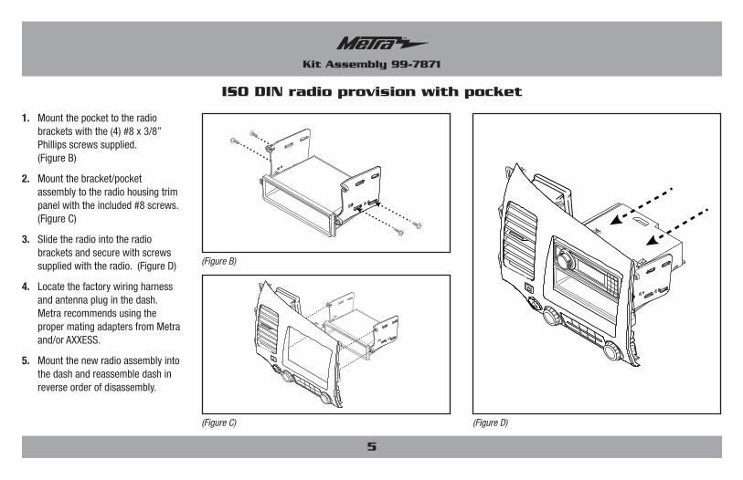
ISO DIN radio provision with pocket
(Figure A2)(Figure A1)
BACK FRONT(6) METAL RETAINING CLIPS
(5)WHITE PLASTICRETAININGCLIPS
Place the (6) metal clips
Place the (5) plastic clips
front back
5
Kit Assembly 99-7871
1. Mountthepockettotheradiobracketswiththe(4)#8x3/8”Phillipsscrewssupplied.(FigureB)
2. Mountthebracket/pocketassemblytotheradiohousingtrimpanelwiththeincluded#8screws.(FigureC)
3. Slidetheradiointotheradiobracketsandsecurewithscrewssuppliedwiththeradio.(FigureD)
4. Locatethefactorywiringharnessandantennapluginthedash.MetrarecommendsusingthepropermatingadaptersfromMetraand/orAXXESS.
5. Mountthenewradioassemblyintothedashandreassembledashinreverseorderofdisassembly.
ISO DIN radio provision with pocket
(Figure C)
(Figure B)
(Figure D)

6
Kit Assembly 99-7871
Note:
Secure the A/C vent, climate control, hazard switch, and the passenger air bag on/off light into the 99-7871 radio housing panel using the factory hardware. (Figure A1)
Position the (6) metal factory retaining clips and (5) plastic white clips onto the radio housing in the same location as the factory radio/climate control panel. (Figure A2)
Continued on next page
Double DIN radio provision
(Figure A2)(Figure A1)
BACK FRONT(6) METAL RETAINING CLIPS
(5)WHITE PLASTICRETAININGCLIPS
Place the (6) metal clips
Place the (5) plastic clips
front back

7
Kit Assembly 99-7871
1. Attachthebracketstotheradiohousingtrimpaneltrimplatewiththesupplied#8x3/8”screws.(FigureB)
2. Fromtheback,slidethedoubleDINradiointothebracket/radiohousingassemblyandsecureusingthescrewssuppliedwiththeradio.(FigureC)
3. Locatethefactorywiringharnessandantennapluginthedash.MetrarecommendsusingthepropermatingadaptersfromMetraand/orAXXESS.
4. Mountthenewradioassemblyintothedashandreassembledashinreverseorderofdisassembly.
Double DIN radio provision
(Figure B) (Figure C)

METRA. The World’s best kits.™ metraonline.com1-800-221-0932 © COPYRIGHT 2004-2014 METRA ELECTRONICS CORPORATION
REV.
7/2
2/20
14
INST
99-7
871
KNOWLEDGE IS POWEREnhance your installation and fabrication skills by enrolling in the most recognized and respected mobile electronics school in our industry.Log onto www.installerinstitute.com or call 800-354-6782 for more information and take steps toward a better tomorrow.
Metra recommends MECP certified technicians
INSTALLATION INSTRUCTIONS FOR PART 99-7871