Embed Size (px)
Citation preview

Application of ultrasonic flowmeters in LNG
D. Laan
KROHNE customer
presentation D. Laan, KROHNE

Application of ultrasonic flowmeters in LNG
Agenda
1. Introduction
2. Transducer and flowmeter design and tests
3. Calibration Concept
4. Flow Tests on Liquefied Nitrogen at NIST
5. Applications
6. Flowmeter verification

3
Introduction KROHNE, history and experience
Experience with ultrasonic flowmeters since early 1980’s
Experience with measuring LNG using Ultrasonic Flowmeters since early
1990’s
Using acoustic wave guides for high and Low temperature sensor design
Osaka Gas – Japan 1990’s

4
Introduction KROHNE, experience
Over 15 years of Experience with Ultrasonic Flowmeters with Fiscal Accuracy
Proven technology in the field
In operation since 1997!
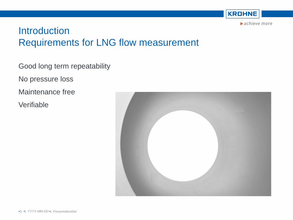
Introduction
Requirements for LNG flow measurement
Good long term repeatability
No pressure loss
Maintenance free
Verifiable
| YYYY-MM-DD 5 | Presentationtitel
Application of ultrasonic flowmeters in LNG
Agenda
1. Introduction,
2. Transducer and flowmeter design and tests
3. Calibration Concept
4. Flow Tests on Liquefied Nitrogen at NIST
5. Applications
6. Flowmeter verification

7
Transducer design
2 possible methods: Wave guide and direct method
Wave guide:
The piëzo kristal is mounted away from the cold or hot medium.
The acoustic signal is guided into the liquid using a wave guide
Direct method:
The piëzo kristal is mounted directly at the liquid behind a 3 mm steel
acoustic window
Piëzo kristal
Direct method Wave guide method

8
Transducer design
Advantage of wave guide method
Electric connection and acoustic coupling in a less extreme environment
Disadvantages of wave guide method
Temperature gradient in wave guide provides unknown transient time of acoustic
signal in wave guide
Difficult to insulate
Heat leakage at transducer area which may provide gas bubbles near the transducer
Ice forming

9
Transducer design
Advantage of direct method
Acoustic signal goes direct into the liquid, only the transient time in liquid is measured
Compact construction
Flowmeter can be completely insulated, no heat leakage, no ice forming
Consequence:
Replacement of transducers is not possible
10
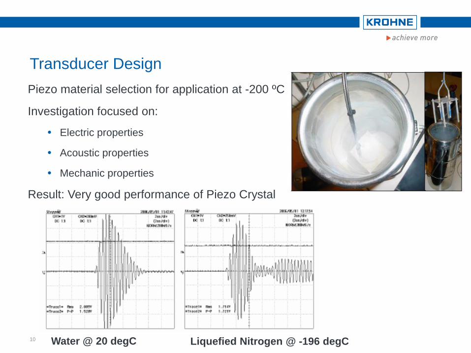
Transducer Design
Water @ 20 degC Liquefied Nitrogen @ -196 degC
Piezo material selection for application at -200 ºC
Investigation focused on:
Electric properties
Acoustic properties
Mechanic properties
Result: Very good performance of Piezo Crystal

12
Transducer Tests
Liquefied Nitrogen @ -196 degC
Transducer submerged in Liquefied N2
Signal is monitored
Temperature shock tests
Durability tests
Result: Stable behaviour and a good
performance
13
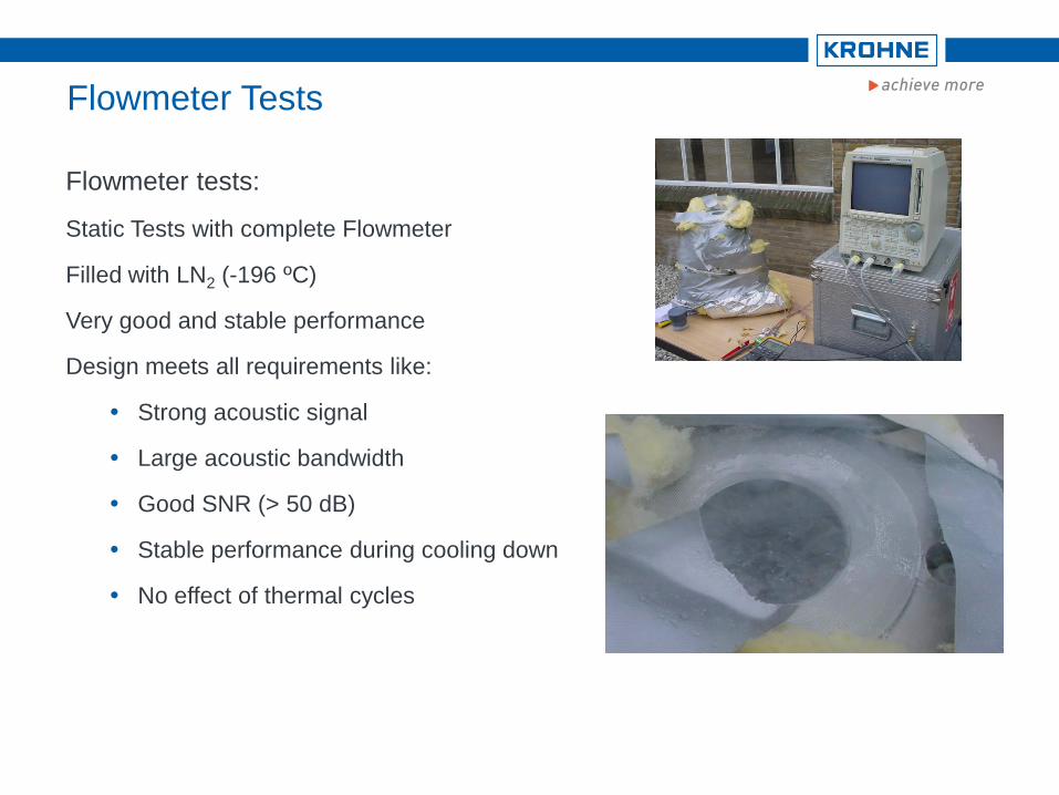
Flowmeter tests:
Static Tests with complete Flowmeter
Filled with LN2 (-196 ºC)
Very good and stable performance
Design meets all requirements like:
Strong acoustic signal
Large acoustic bandwidth
Good SNR (> 50 dB)
Stable performance during cooling down
No effect of thermal cycles
Flowmeter Tests

Application of ultrasonic flowmeters in LNG
Agenda
1. Introduction,
2. Transducer and flowmeter design and tests
3. Calibration Concept
4. Flow Tests on Liquefied Nitrogen at NIST
5. Applications
6. Flowmeter verification

15
Calibration Concept
No LNG calibration facility available (yet), with good reference
Calibration procedure has been developed
Transfer calibration at ambient conditions to application at cryogenic condition
The following items have been into account:
Uncertainty calibration rig
Thermal expansion
Linearity → Reynolds calibration
16
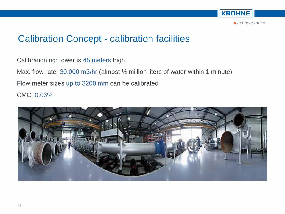
Calibration Concept - calibration facilities
Calibration rig: tower is 45 meters high
Max. flow rate: 30.000 m3/hr (almost ½ million liters of water within 1 minute)
Flow meter sizes up to 3200 mm can be calibrated
CMC: 0.03%

17
Calibration Concept – Thermal Expansion
Illustration using ALTOSONIC III
Liquid: Water
Tests at 20ºC, 50ºC and 80ºC
Uncorrected Flow at 20, 50 and 80 degC
-0,5
-0,4
-0,3
-0,2
-0,1
0
0,1
0,2
0,3
0,4
0,5
0 50 100 150 200
Volume flow [m3/h]
Devia
tio
n [
%]
20 degC 50 degC 80 degC

18
Calibration Concept – Reynolds calibration
Corrected for Thermal expansion
Plotted as function of Reynolds number (taking into account changing viscosity)
Flow corrected for thermal expansion and plotted as
function of Reynolds number
-0,5
-0,4
-0,3
-0,2
-0,1
0
0,1
0,2
0,3
0,4
0,5
0,0E+00 5,0E+05 1,0E+06 1,5E+06 2,0E+06
Reynolds number [-]
dev
iati
on
[%
]
20 degC 50 degC 80 degC
Application of ultrasonic flowmeters in LNG
Agenda
1. Introduction,
2. Transducer and flowmeter design and tests
3. Calibration Concept
4. Flow Tests on Liquefied Nitrogen at NIST
5. Applications
6. Flowmeter verification

20
Test on Liquefied Nitrogen at NIST
Test rig in USA
NIST, Boulder, USA
Cryogenic Test rig on liquefied Nitrogen
Temperature: -193 [ºC] to -183[ºC]
Pressure range: 4 to 7.6 [bar]
Flow range: 4.5 to 45 [m3/h]
Reference: Weighing Tank
Overall uncertainty on totalized mass flow: 0.17%
(k=2) (in range 4.5 to 45 m3/h)
ALTOSONIC V 10 D
DN50 (2”) DN100 (4”)
21
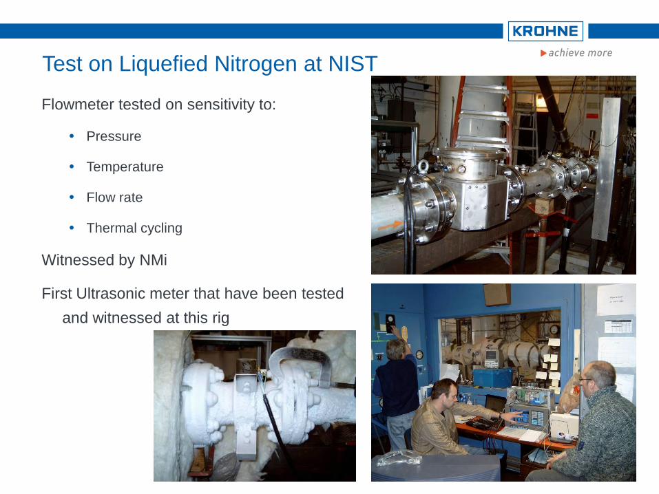
Test on Liquefied Nitrogen at NIST
Flowmeter tested on sensitivity to:
Pressure
Temperature
Flow rate
Thermal cycling
Witnessed by NMi
First Ultrasonic meter that have been tested
and witnessed at this rig
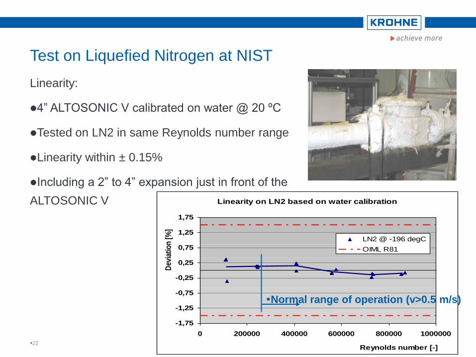
Test on Liquefied Nitrogen at NIST
Linearity:
4” ALTOSONIC V calibrated on water @ 20 ºC
Tested on LN2 in same Reynolds number range
Linearity within ± 0.15%
Including a 2” to 4” expansion just in front of the
ALTOSONIC V
22
Linearity on LN2 based on water calibration
-1,75
-1,25
-0,75
-0,25
0,25
0,75
1,25
1,75
0 200000 400000 600000 800000 1000000
Reynolds number [-]
Dev
iati
on
[%
]
LN2 @ -196 degC
OIML R81
Normal range of operation (v>0.5 m/s)

23
Test on Liquefied Nitrogen at NIST
Results
Sensitivity to pressure and temperature:
No sensitivity to pressure and temperature has been observed (in the range of the rig)
No effect has been measured as a result of thermal cycles
Reproducible results after several thermal cycles
Linearity
Linearity is better than ± 0.15% based on water curve
Even for flow rates down to 1.5% of F.S.
Repeatability and Stability
A complete flow rate cycle is done between collecting each flow rate point
A repeatability of ± 0.07% has been obtained in the normal flow range
Even at 1.5% of F.S. a very good and stable performance is observed

Test on Liquefied Nitrogen at NIST
Results
Uncertainty analysis in cooperation with NMi
Uncertainty statement NMi
With these data the uncertainty is expected to be < 0.2%
24
Application of ultrasonic flowmeters in LNG
Agenda
1. Introduction,
2. Transducer and flowmeter design and tests
3. Calibration Concept
4. Flow Tests on Liquefied Nitrogen at NIST
5. Applications
6. Flowmeter verification

Applications, LNG import terminal
Enagas, Spain
26
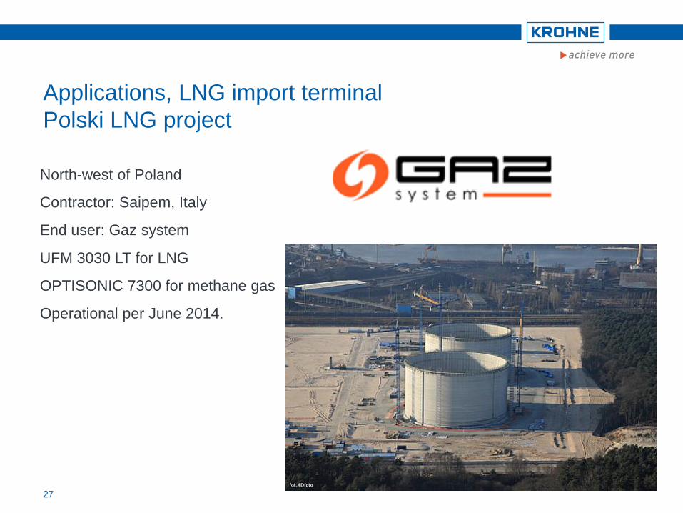
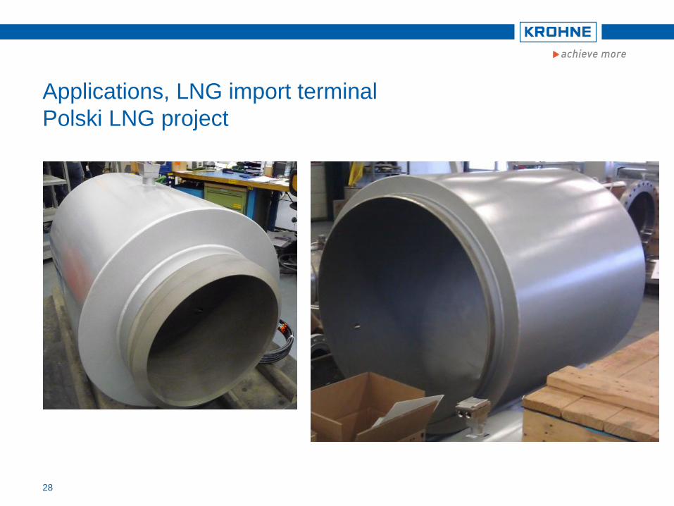
Applications, LNG import terminal
Polski LNG project
North-west of Poland
Contractor: Saipem, Italy
End user: Gaz system
UFM 3030 LT for LNG
OPTISONIC 7300 for methane gas
Operational per June 2014.
27
Applications, LNG import terminal
Polski LNG project
28
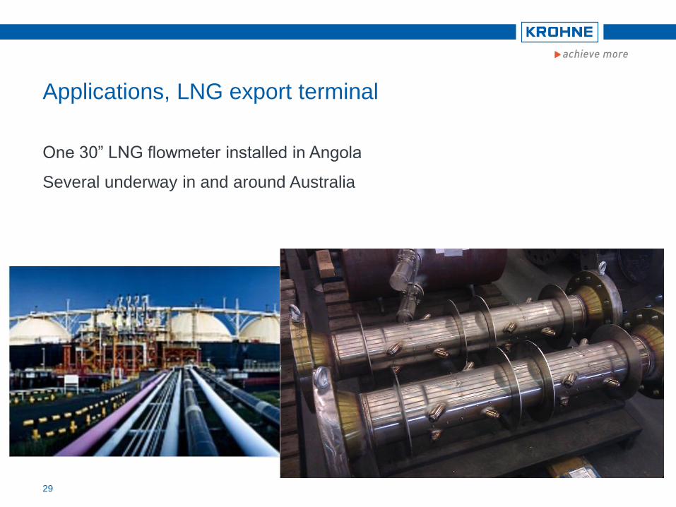
Applications, LNG export terminal
One 30” LNG flowmeter installed in Angola
Several underway in and around Australia
29
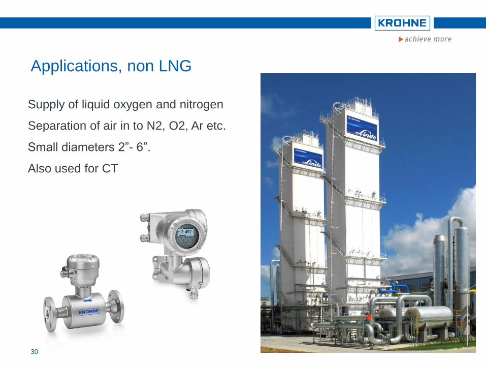
Applications, non LNG
Supply of liquid oxygen and nitrogen
Separation of air in to N2, O2, Ar etc.
Small diameters 2”- 6”.
Also used for CT
30
Application of ultrasonic flowmeters in LNG
Agenda
1. Introduction,
2. Transducer and flowmeter design and tests
3. Calibration Concept
4. Flow Tests on Liquefied Nitrogen at NIST
5. Applications
6. Flowmeter verification

32
Typical advantages
No moving parts, no wear, no
maintenance, no recalibration
Excellent long term repeatability
No obstructions in the pipe, no
pressure loss
Flowmeter verification
Ultrasonic flow meters
transducer A
transducer B
D

Flowmeter verification
Standard product for cryogenic applications
OPTISONIC 3400
Robust all welded stainless steel construction
DN25…DN3000 (1”…120”)
Liquid temperatures as low as minus 200°C (-328°F)
External sensor housing for easy insulation and avoidance of icing
IP68 (NEMA 6P) ingress protection in case of condensation
Hazardous area approvals: ATEX zone 1, IEC-Ex
Remote converter

Measurement accuracy
± 0,3% of m.v. ± 2 mm/s under ref. conditions
Bidirectional flow measurement at nearly zero flow:
0,3...20 m/s (1...66 ft/s)
For process temperature range of
–200...+250°C (-328...+482°F)
Inlet/outlet conditions: min. 5D/3D
For complete diameter range DN25....3000 (1...120
inch) always a 3-beam ultrasonic sensor
construction
Flowmeter verification
Standard product for cryogenic applications
TBA - TAB ~ vMedium

Flowmeter verification
Diagnostics NAMUR NE107 on all communication
protocols for status messages and error
handling
Status messages are grouped
Group, or priority can be changed by user or switched off
F Failure
S Out of specification
M Maintenance required
C Function check

Flowmeter verification
Diagnostics
F F Sensor – crossed cabling
C C Configuration – flow simulation,
VoS simulation
S S Proc: Empty pipe
S S Proc: Signal lost (per path)
S S Proc: Signal unreliable (per path),
flow profile
Flowmeter verification
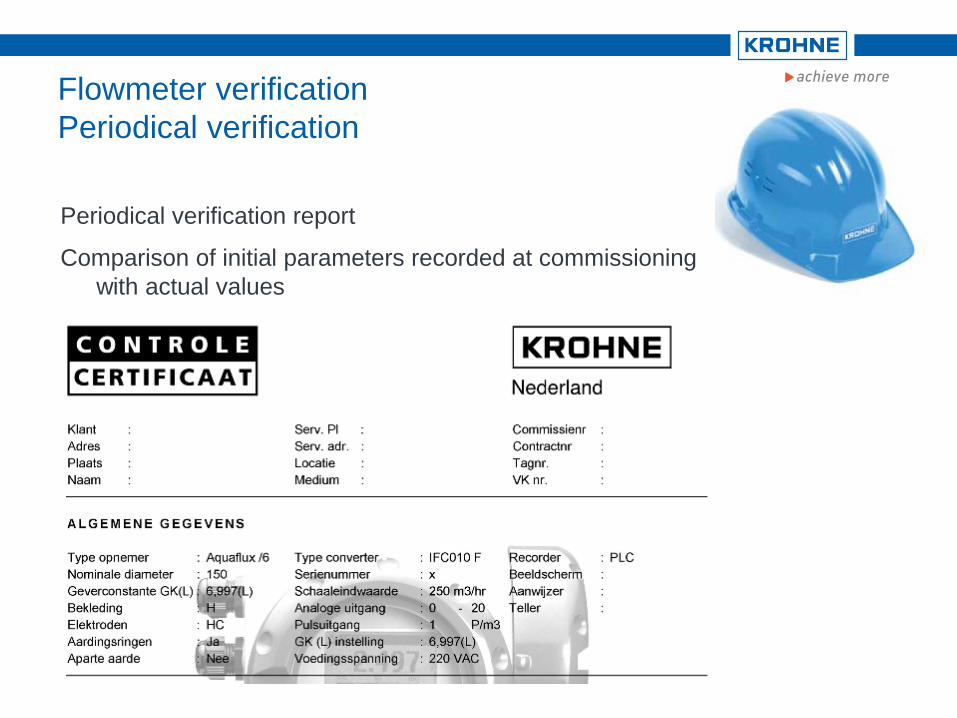
Periodical verification
Periodical verification report
Comparison of initial parameters recorded at commissioning
with actual values

Conclusion
Requirements for LNG flow measurement
Good long term repeatability!
No pressure loss!
Maintenance free!
Verifiable!
REQUIREMENTS FULFILLED!
| YYYY-MM-DD 38 | Presentationtitel
Thank you for your attention!