Embed Size (px)
Citation preview

1
ANALYTICAL DESIGN OF ROCK-BOLT SYSTEMS
“Imagination is more important than knowledge” Albert Einstein 1.INTRODUCTION Some forty years ago, most opening supports and reinforcements were designed using
empirical rules defining ground loads acting on the supporting structures. This approach is
still popular and interest in it has been renewed by the use of rock mass classification systems
(Barton et al. 1974, Bieniawski, 1974,1976,1989). Correlations between rock mass conditions
and the type of support used are based on case histories. This approach perpetuates existing
practice, even if over-conservative or unsatisfactory.
Most recent underground excavation design relies on more elaborate analysis of the
complex rock –support interaction. Moreover, the effect of geometry of opening has to be
allowed for. A new concept of RRE (Rock-mass, Rock-bolt, Excavation) which will be
developed in thesis, is intended to cover all parameters involving in design of a proper
reinforcement system. This concept must take into account not only the properties of rock
mass, but also the structure behavior of the reinforcing structure (element) and the opening
geometry. Stresses and displacements in the rock mass surrounding openings depend upon the
rock mass properties, the in-situ initial stress field, opening shape, and the type (stiffness) of
This technical article has been submitted to Rock Mechanics’ research and development (R&D) of mining engineering department of Middle East Techical University as an advanced study. Author: Eng. Reza Rangsaz Osgoui Tutor: Prof.Dr. Erdal Unal Summer 2003, Ankara- Turkey

2
the support and the time of its installation. In this study, the time –independent effect is
disregarded.
A complete analysis requires a larger amount of data and information, which may be taken
into account by numerical modeling. However, in most cases it is difficult to obtain all
necessary data before construction. Many of the parameters that influence the analysis are ill-
defined and, up to now, no perfect constitutive model has been shown to be successful at
simulating all the aspects of rock behavior important to design of reinforcement systems for
underground excavations. Some rock properties may only be evaluated by back-analyzing
field data.
A good understanding of the deformations (the most dangerous phenomenon) caused by an
underground opening requires simultaneously knowledge of the rock-support interaction and
interpretation of field data. Assessing the stress acting on reinforcement system as well as
displacements occurring during and after construction is the main purpose of analytical
methods in designing a proper reinforcement system for defined opening. The measurement of
the wall’s displacements, commonly called “ convergence” is indeed the one most used on a
opening site.
2.GENERAL REMARK In this stage of design of rock-bolt systems, an extensive literature survey conjunction with
analytical models of passive rock-bolts is fully discussed. To date, a large number of
analytical solutions have been obtained for rock-bolt design. It is clear that rock mass
reinforcement techniques, such as by means of fully grouted bolts or cables, have been
applied to openings, but theoretical problems have been encountered in the design of this
reinforcement scheme with analytical axisymmetric models due to the difficulty of
considering the influence of the passive bolt and the rock mass rock-bolt interaction (RR from
RRE concept). Analytical axisymmetric models that can define the stresses and deformation
induced by excavation (convergence-confinement method) are widely used in the design of
excavation and reinforcement system due to the computational simplicity. Many analytical
formulations for the calculation of the ground characteristics curve have been developed and a
number of models, based on either the Mohr-Coulomb or the Hoek-Brown strength criterion
with elastic-plastic or elastic-brittle plastic stress-strain behavior have been adopted. Some
models with a strain softening behavior with non-linear strength criteria, and associated or
non-associated flow rules have also been presented.

3
Table 1.Material (rock mass) behavior models used in rock-bolt design.
Author / Year Strength/Yield Criterion
Stress-Strain Model
Treatment of plastic volumetric strains
Indraratna & Kaiser
1987,1990
Mohr-Coulomb (linear)
elastic-brittle plastic
non-associated flow rule
Peila & Oreste 1995,1996,1997,
2003
Hoek & Brown (non-linear)
strain-softening
associated flow rule applied over limited
range of post peak strain
Hoek & Brown 1980,1983
Hoek & Brown(non-
linear)
elastic-brittle plastic
associated flow rule applied over limited
range of post peak strain
Stille et al. 1983,1989
Mohr-Coulomb (linear)
elastic-brittle plastic
non-associated flow rule dilatancy after failure
In order to better understand of rock-bolt and rock mass interaction (RR of RRE Concept), it
is essential to get a good sense of material (rock) behavior, by means of which some important
analytical design approaches have been developed (see Tabale1). The material behavior
models used in analytical solution of rock-bolt design are illustrated in the Figure1 and 2.
Figure1. Material behavior model in the case of
Elastic-brittle plastic (after Brown et al. 1983).
Figure2. Material behavior model in the case of the
strain -softening (after Brown et al. 1983).

4
In general, rock reinforcement with different types of rock-bolts can be assessed with
analytical solutions based on the theories of the ground reaction curve (Hoek & Brown, 1980,
Brown et al. 1983, Stille et al.1989, Oreste & Peila, 1995,1996,1997,2003).
The arising deformations and stresses around an excavation in rock are a result from the
interaction between rock mass and rock support. Analytical solution can be achieved under
certain conditions. The problem is often solved for a circular opening in a hydrostatic stress
field and presented in a ground-support interaction diagram with the ground reaction curve
and the reaction line of the support (see Figure 3).
Figure 3. The convergence–confinement method. Key: p: internal opening pressure; u: radial displacement of the wall (positive towards the
opening axis); po : in situ hydrostatic stress; peq : pressure acting on the support structure; pmax : pressure that induces the plastic failure of the structure (support capacity); k: support stiffness; uin : displacement of the wall before support installation; ueq : displacement at equilibrium; uel : displacement of the wall on reaching the elastic el limit in the support; umax : displacement of the wall on collapse of the max support; and A: equilibrium point of the opening-support system.
Many approaches to the calculation of the ground reaction curves for different types of rock
mass behavior (see Table 1) have been reported in the literature. Brown, Bray, Ladanyi and
Hoek (1983) have compiled a comprehensive report on the subject. They presented a stepwise
method based on finite difference method of solving the partial differential equation for strain
softening behavior of rock mass apart from normal method, which had been introduced earlier
(Hoek & Brown, 1980).
Here let’s briefly argue about grouted (in general name friction bolt) and prestressed types
of bolt, which have been recently a debatable subject. The reaction line of a rock support with
anchor bolts has been presented elsewhere(Hoek and Brwon 1980, Oreste 2003). The anchor
bolt is connected to the rock in the anchoring zone and at the anchor head. Between these two
connection points the rock is free to deform independently of the bolt. The most common
anchor types are mechanical, cement grout, and chemical. The load in the rock-bolt is
transferred to the opening surface at the anchor head through a nut and a washer plate.
The reaction line for a support with anchor bolts cannot be used for grouted bolts since the
grouted bolts don’t act independently of the rock. The deformations in the rock cannot be
separated from the deformations in the bolt since the bolt and rock is grouted together. In such

5
a cases the bolts will interact with the rock and influence the ground reaction curve of the rock
mass.
Over the years, on the other hand, there has been much debate as to whether tensioned bolts
or untensioned grouted bolts are more suitable for stabilizing rock openings. The question of
whether to use tensioned bolts or untensioned grouted bolts is not of minor importance.
Except from economic point of view, tensioned bolts are commonly used all over the world
with the explanation that they are recommended in the empirical design method and will give
the most efficient. It is doubtful whether this will in fact be achieved. The Q-system (Barton et
al. 1974), for example, is such as an empirical method based on roughly 200 case records and
therefore can be conservative. It reflects traditional support methods for advanced opening
construction technique, which are not always the optimal ones. The Q-system recommends
mainly the use of tensioned bolts for poorer rock qualities and untensioned bolts only for good
and very good rock.
On the other side, in the Q-system, for many ground categories, particularly in poor,
yielding rock it does not generally recommend the installation of untensioned grouted bolt or
sweelex bolt. Therefore, it is not meaningful to compare the proposed analytical approached
with the Q-system. The geomechanical classification or rock mass rating (RMR) developed by
Bieniawski (1974,1979,1989) is, however, applicable to fully grouted bolts in all types of
rock; accordingly: the analytical approaches in some cases can be compared with empirical
reinforcement design.
Swidesh experience of rock-bolting today is that almost without exception untentioned
grouted bolts and swellex bolts are utilized for every type of rock condition. Some technical
report conducted by others in Sweden underlined the good experience from support systems
using untensioned grouted bolts and shotcrete in poorer rock. Therefore, the behavior of
grouted bolts as well as swellex bolts will mainly be analyzed in the thesis.
In the following, four constitutive models developed for the design of rock-bolt system
based on analytical methods will be discussed. In is of great importance to utterly acquaint
with those models involving the rock-bolts, rock mass interaction.
3. AXISYMMERTIC OPENING PROBLEM
Many authors have calculated the ground reaction curve of the rock mass for different
failure criteria of the rock (Brown et al. 1983). For an elastic- brittle-plastic rock mass
material with a Coulomb’s failure criterion for both the peak and residual strength and a non-

6
associated flow rule in which post-peak dilatancy occurs at a constant rate with major
principal strain, the following solutions of the ground reaction curve will be achieved. This
solution has been employed both Stille et al. (1983,1989) and Indraratna & Kaiser
(1987,1990) (see Figure 4).
The stress-strain relation of the rock mass
is illustrated in Fig.1. In the plastic
(yielding or broken) zone nearest to the
opening surface of the Figure4.The axisymmertic opening problem
circular opening the following tangential
stresses, σt, and radial stresses, σr, will
occur:
r
k
irrit a
rrkap
r
−
+=
−1
)(σ (1)
r
k
irit a
rrap
r
−
+=
−1
)(σ (2)
where:
,2
45tan
,tan
2
+=
=
rr
r
rr
k
ca
φ
φ
cr= residual value of the cohesion,
φr= residual value of the friction angle,
ri= radius of opening,
pi= outward radial pressure on the
opening surface.
The boundary, re, between the zones of plastic and elastic behavior can for a rock mass with
initial state of stress po be calculated with the following expression:
( )1
1
12 −
+
−
−++=
rk
ri
ro
i
e
ap
aaapk
rr (3)
Above equation can also define the extent of the yielding zone where:

7
,2
45tan
,tan
2
+=
=
φ
φ
k
ca
c= cohesion,
φ= friction angle.
The stress outside the plastic zone (i.e. elastic zone), r>re, can be achieved with the following
equations:
,)(2
−−=
rrpp e
oreot σσ (4)
,)(2
−+=
rrpp e
oreor σσ (5)
where:
aapk ore −+
+= )(
12σ (6)
σre is the radial stress at the elastic-plastic boundary.
The deformations of the opening surface, ui, can be computed as:
,)1(21
1
−+
+
=+
frr
fAru
f
i
eii (7)
where
( )reopE
A σν−
+=
1 , (8)
and
E= Young’s (elasticity) modulus of rock mass
ν=Poisson’s ratio of rock mass,
po= in-situ stress
the factor f expresses the volume expansion after failure and is given by:
−+
+
=ψϕ
ϕ
245tan
245tan
f , (9)
where ψ= dilatancy angle.

8
Equation (7) is derived from the approximation that the rock mass is subjected to elastic
strains in the plastic zone that are constant and equal to the elastic strains at the boundary
between the zones of plastic and elastic behavior.
4.FLOW RULE OF PLASTICITY CONCEPT
No analytical model cannot introduce the real interaction between rock–bolt and rock mass
around a opening provided that the real behavior of them is realized. At the failure point and
post –peak behavior of a rock, it is important to determine the post-peak parameters of rock
due to their applicability the analysis of the broken zone deduced as well as reinforced rock
mass. Flow rule is recognized to be a tool, whereby; post peak parameters of rock can be
determined based on selective yield condition. In what follows, we will assume that elastic
stress increments have been computed and that both yield conditions are exceeded; later on,
the condition for separate yielding will be given. The usual assumption is made that the
overall strain increment of an element can be decomposed into elastic and plastic parts and,
further, it is assumed that the plastic contributions of shear and volumetric yielding are
additive. The principal axes of both plastic and elastic strain increment are taken to be coaxial
with the principal axes of stress (only valid if elastic shear strains are small compared to
plastic strains); the strain increments obtained are: pv
ips
ie
ii eeee ∆+∆+∆=∆ (10)
Where i=1,3 and superscripts psandpv stand for “plastic shear” and “plastic volume”,
respectively. The flow rules for shear and volumetric yielding are:
i
ss
psi
ge
σλ
∂∂
=∆ and i
vv
pvi
fe
σλ
∂∂
=∆ (11)
It can be shown that the volumetric flow rule is associated and the shear flow rule is non-
associated. The plastic potential for shear yielding is:
ψψσσ NcNgs 231 +−= (12)
where Nψ = (1+sinψ)/(1-sinψ), and
ψ is the dilatancy angle.

9
An alternative approach to the use of experimentally determined parameters in defining the
post-peak volumetric strain is to estimate them using the associated flow rule of the theory of
plasticity. Hoek and Brown (1980) have previously used this approach in their closed from-
solution. When an associated flow rule applies, the yield criterion and the plastic potential
function are the same functions of the stress components. In other words, the flow rule is
referred to as associated if the plastic potential and yield surface coincide. As a consequence
of this, the plastic strain increment vector must be normal to the yield surface. If the yield
surface is represented by a relation between principal stresses, σ1 and σ3, then the
corresponding components of the strain increment vector are the increments of ε1pand ε3
p. If
the flow rule is non-associated, the yield criterion and the plastic potential function are not the
same and the normality principles do not apply. There is limited evidence available to suggest
that the dilation rate at peak stress in dense brittle rocks or tightly interlocked aggregates can
be predicted closely using the associated flow rule. It is not clear, however, that the associated
flow rule applies to heavily fractured and poorly interlocked rock masses. Indeed, analyses of
data obtained from Brown et al.(1983) suggest that, in some such cases, the flow rule will be
non-associated. This means that the resulting plastic volume changes will be less than those
predicted using an associated flow rule.
More recently, based on analyses undertaken by Indraratna (1987), a flow rule applicable to
a linear Mohr-Coulomb failure criterion, has been adopted:
0=+ ppr θαεε (13)
The parameter α is the dilation coefficient that characterizes the volume change in the
plastic zone. Zero volumetric strain (no volume change) is represented by α=1. If α=m, the
associated flow rule is obtained for a Mohr-Coulomb material where m=tan(45+ ϕ/2). For a
material with a friction angle of 30°, a value
of α=3 is a upper
bound. The associated low assumes that
the plastic strain increments are normal to
the failure envelope (2-D problem)
satisfying normality condition, thereby
generally overestimates the plastic strains in
rock. Therefore, a non-associated flow rule
Figure 5. Mohr-Coulomb linear
failure criterion and flow rule

10
(1<α<m) is more realistic, as illustrated by Figure 5.
A further attention has to be taken in differences between brittle material and plastic
material (i.e. ideal plastic such as clay). Only for 1<α<3 the non associated flow rule satisfies
the brittle material because for a brittle rock, α=3 is a upper bound realized by non-associated
flow rule whereas for α>3 and α=1 a plastic behavior occurs satisfied by a associated flow
rule. A good definition for these hypotheses was studied by Peila et al. (1995) and Cividini
(1993).
5. ANALYTICAL APPROACHES FOR ROCK-BOLT DESIGN
In this part of study, some crucial methods employing analytical methods for rock-bolt
design conducted by others are extensively argued so that a complete and extensive literature
on subject will be achieved. It is so convincing, at this point, that such constitutive models of
rock-bolt design are mainly divided into two categories based on material behavior model and
failure criteria.
PART A: LINEAR CONSTITUTIVE MODEL
USING NON-ASSOCIATED FLOW RULE AND
MOHR-COULOMB YIELD CONDITION
5.1. STILLE’S CONSTITUTIVE MODEL
Stille et al. (1983,1989) presented a closed-form elastic-plastic solution of grouted bolts by
considering five different approaches of bolt performance which, even though introducing
some simplifying assumptions, have proved to be in good agreement with measured data. In
Stille’s approach, the analysis of ground reaction curve for a rock mass with grouted rock-
bolts is considered. In order to model the rock-bolt and rock mass behavior five following
categories are taken into account.
a) Elastic condition
b) Elastic bolt in a plastic rock mass
c) Plastic bolt in a plastic rock mass
d) Plastic deformation of the grouting material
e) Elastic bolt with nut and end-plate and plastic deformation of the grout material

11
Elastic condition
In the elastic condition grouted bolt improves the rock mass in terms of deformation
modulus and stiffness. With the condition that the rock and the bolt will have the same strain
the effective modulus Eeff can be obtained according to the theory of composite material and
will get the following:
lc
sbeff SS
YEEE
⋅⋅
+= (14)
where Eb and Es are the modulus of the rock mass and steel respectively and Y is bolt area.
The bolt load T can be calculated from the following system of equations:
ru
r ∂∂
−=ε (15a)
rr
pE
u eore
eff
2
)(1⋅−⋅
+= σν (15b)
rEYT ε⋅⋅= (15c)
The load will then be:
YEr
rp
ET s
eore
eff
⋅⋅⋅−⋅+
= 2)()(1 σν (15d)
Elastic bolt in a plastic rock mass
In the case of the elastic bolt in a plastic rock mass it is assumed that bolt distances are so
small and rock mass and rock-bolt have the same strain, furthermore the occurrence of a
tensile load in the bolt will imply a corresponding additional compressive stress in the rock
mass. Radial stress in the rock mass will then be the sum of the outer stress, σr, and the above
mentioned additional compressive stress. The equilibrium partial differential equations in the
polar coordinate will occur:
0=∂∂
−−r
r rrt
σσσ (16)
clrb SS
T−= σσ (17)
rb
rtr a
ak
++
=σσ (18)

12
ssEYT ε= (19)
Equation 16 is the condition of equilibrium for an infinitesimal element; equation 18 is the
Mohr-Coulomb failure criterion for a rock mass with residual values on cohesion and friction
angle. Equation 19 is the bolt stress from the plastic strain given by:
elrs εεε −= (20)
Where the elastic strain, εel is assumed to be constant in the plastic zone and equal to:
)(1reoel p
EA σνε −
+==− (21)
Equation 21 is equal to the elastic strain at the boundary, r=re, between the zones of elastic
and plastic behavior. The radial deformations, ur, and the total radial strain,εr, depend on the
properties of the rock mass and are obtained from:
,)1(21
1
−+
+
=+
frr
fAru
f
i
eii (22)
ru
r ∂∂
−=ε (23)
By combining equations (20-23) and 19 the bolt load, T, can be eliminated from equation17.
The stress in the rock,σb, can then be omitted with equation18. Therefore, the tangential
stress, σt, can be eliminated from equation 16 and the following partial differential equation
will result:
4
1
3)1( Crr
Ckr
rf
err
r −
=−+
∂∂ +
σσ (24)
This differential equation will have the following solution:
r
fe
r
kr k
Crr
kfC
rC r
−−
+−=
+−−
14
13)1(
5σ (25)
The C5 can be determined from the boundary condition in the way that the radial
stress,σr=pi, at the opening surface, r=ri. The radial stress will then be:
++
−−
+
+−
+=+−+ 1
34
11
34
11
fe
rr
k
i
f
i
e
rrir r
rkf
Ck
Crr
rr
kfC
kC
pr
σ (26)

13
The boundary between the zones of elastic and plastic behavior r=re, can then be found
from the conditions that the radial stress, σr, shall be continuous over the boundary and the
failure criterion for the peak values are fulfilled.
The ratio re/ri or the extent of the yielding can be solved by trial-and –error form:
11
134
34
1
1
−
+
++
−+
++
−+
=
rk
fe
rri
rrre
i
e
rr
kfC
kCp
kfC
kC
rr
σ (27)
where
YEf
AfSS
kC scl
r
12
3 +⋅=
rrrscl
r aakYEf
AfSS
kC +−+
⋅=1
24
The bolt load can then be obtained from the following equation:
−
+=
+1
11
2 fe
s rr
ffAYET (28)
where err ≤ .
The bolt load will be in tension with its maximum tensile load at the opening surface and the
tensile load will decrease into the rock. This occurrence have been previously proved by
Freeman 1978,Zhen Yu et all. 1983, and Xueyi 1983. Besides, Indraratna 1990 pointed out
that by shear stress transmission from the rock to the bolt surface the axial tension would
occur.
Plastic bolt in a plastic rock mass
If the interaction between the bolts an d the rock mass is ideal and the end plate stiff the
bolts will be subjected to high loads close to the opening surface. This implies yielding of the
bolt if the ultimate strength is exceeded.
Under these conditions two zones will be developed around the opening (see Figure6):
Plastic rock and elastic bolt,

14
Plastic rock and plastic bolt.
In the zone closet to the opening, the stress situation can be derived like the previous
solution with the exception that the bolt load has to be replaced by ultimate strength of bolt
(yielding load of bolt) Tmax.
As brief, the radial stress can be solved in terms of Tmax:
−
−−
−
−+=−
11max
1
max
r
r
lcr
k
ir
r
lcrir k
kSS
Ta
rr
kk
SST
apr
σ (29)
The extension of the zone with plastic rock and plastic bolt (this zone was named with
Equivalent Plastic Zone EPZ by Indraratna) can be calculated through the conditions that the
bolt load and radial stress shall be continuous over the boundary r=rp. In the zone with plastic
rock and elastic bolt, equations (26-28) are valid if ri is replaced by rp and pi with σrp. The
values of re and rp can then be calculated by trial and error with the following equations:
−
+=
+1
max 11
2f
p
es r
rf
fAYET (30)
−
−−
−
−+=−
11max
1
max
r
r
lcr
k
i
p
r
r
lcrirp k
kSS
Ta
rr
kk
SST
apr
σ (31)
Plastic deformation of the grouting material
Common types of grouted bolt are not equipped with a special anchor head. For this types of
bolt the bolt load will be zero at the opening face and increase inwards. The plastic
deformations of the rock mass will be largest close to the opening surface and the shear
strength of the grouting may be exceeded, in which case sliding will occur. The bond between
Figure 6. Rock and bolt conditions in the rock mass

15
the bolt and the rock mass is considered to be plastic and only transfer a constant shear load
per unit length, τ, to the bolt. If it is then assumed that the shear load can be equally
distributed out into the rock mass, the following equations are obtained:
lc
irrt SS
rr
rτσ
σσ −=∂∂
−− (32)
rb
rtr a
ak
++
=σσ (18)
)( irrT −−= τ (33)
The load in the bolt will increase linearly from zero value at the opening face. the shear
load, τ, transferred from the bolt can be interpreted as a volume load radial directed out from
the opening. The stresses acting on the rock, σb, will not be influenced by the bolt load,T, but
indirectly by the shear load. The only connection between the rock and the bolt is the shear
load and not the total bolt load. The radial stress, σr, wills for this case be the same as the
stresses acting on the rock mass, σb. The partial differential equation of equilibrium will be
different from the earlier case since the shear load will influence the equilibrium of a
infinitesimal element as shown in Figure 7. Under these conditions, two zones will be
developed surrounding the opening as shown in Figure 8. By combining equations 32 and 18,
a distinguished differential equation will be established and using the boundary conditions at
opening face the radial stress will then be:
Figure 7. Stresses in the bolt and rock at plastic deformation in the grouting material (a) Stresses in the bolt. (b) Stresss in the rock.

16
−−−
−−+=
−
11
11 1
rlc
ir
k
irlc
irir kSS
ra
rr
kSSr
apr ττ
σ (34)
The extension of the zone with plastic rock and plastic bolt (this zone was named with
Equivalent Plastic Zone EPZ by Indraratna) can be calculated through the conditions that the
bolt load and radial stress shall be continuous over the boundary r=rp. In the zone with plastic
rock and elastic bolt, equations (26-28) are valid if ri is replaced by rp and pi with σrp. The
values of re and rp can then be calculated by trial and error with the following equations:
)( ipp rrT −−= τ (35)
−
+=
+1
11
2f
p
esp r
rf
fAYET (36)
−−−
−−+=
−
11
11 1
rlc
ir
k
i
p
rlc
irirp kSS
ra
rr
kSSr
apr ττ
σ (37)
Elastic bolt with nut and end-plate and plastic deformation of the grout material
For a grouted rock-bolt with a nut and end
plate, plastic deformation can occur in the
grouting material before the yield strength
of the bolt reached, due to low bond
strength. Sliding in the bond between rock
and the bolt then starts at the opening
surface where the grouting material is
assumed to be in a plastic condition and
only able to transfer a constant shear load
Figure 8. Rock and grout conditions in the rock mass
Figure 9. Interaction between rock mass and bolt with end plate. Local deformations of the rock mass under the end plate is shown.

17
between rock mass and bolt. It is
interesting at this point that the bolt load is
not zero at the opening surface because of
the interaction with the end-plate. The
magnitude of the bolt load at the opening
surface depends on the bearing capacity of
the rock mass under the end plate, see;
Figure 9.
Similar to previous model, two zones with different conditions in the support and the rock
will develop (see Figure 8). According to the theory of elasticity and assuming a circularly
distributed load, the deformation of the rock mass under the end plate is obtained by:
EDT
u ee
)1( 2ν−= (38)
where
Te= bolt load due to effect of end-plate
E= Young’s modulus of the rock mass
D= diameter of the end-plate
The deformation in the rock mass under the end plate is also governed by:
)()( sgrpie uuuuu +−−= , (39)
where
ui= deformation of rock mass at surface, r=ri,
up= deformation of rock mass at r=rp,
ugr= deformation of bolt due to bond load,
us= deformation of bolt due to loading of end-plate.
Rock deformation at the opening surface, ui, and at the boundary between plastic and elastic
grout, up, is calculated from:
Arfrr
fAr
u i
f
i
er +
−+
+
−=+
)1(21
1
(40)
where, r=ri and r=rp respectively and A and f are computed by equations (8) and (9). The
deformation in the bolt is:
Sgr YE
xu2
2τ−= (41)
s
es YE
xTu = (42)
where x=rp-ri

18
The equilibrium differential equation will be:
lc
irrt SS
rr
rτσ
σσ −=∂∂
−− (32)
rb
rtr a
ak
++
=σσ (18)
ei TrrT +−−= )(τ (43)
The solution of above differential equation is like previous case, hence:
eip TrrT +−−= )(τ (44)
−
+=
+1
11
2f
p
esp r
rf
fAYET (45)
−−−
−−+=
−
11
11 1
rlc
ir
k
i
p
rlc
irirp kSS
ra
rr
kSSr
apr ττ
σ (46)
Where Te is obtained from equations 38 to 42 as:
( )
+
−
+−=
s
spi
e
YEx
ED
YExuu
T)1(
22
2
ν
τ
(47)
A hypothetical example is shown to elucidate the different performances of grouted bolt in
the aforementioned analyses. Figure 10 shows the analytical bolt load distribution curves
along the bolt according to equations 28,30,35, and 43. The analytic solutions correspond to:
Figure 10. The different analytic bolt load distributions of a grouted bolt.

19
i. The bolt is in elastic condition and the interaction between rock mass and bolt is ideal.
The required bond strength, highest close to the opening surface and decreasing
inwards, is numerically equal to the inclination per unit length of the bolt load curve
in every point along the bolt. The stiffness of the end plate is infinite.
ii. In the outer part of the bolt, the yield strength of the bolt is exceeded. The interaction
between rock mass and bolt is ideal and a perfect plastic behavior of the bolt is
assumed.
iii. The bolt is without end-plate and in elastic condition. The shear strength of the
grouting material is exceeded in the outer part of the bolt. In that zone, the bolt load
only depends on the residual capacity of the grout to transfer load between rock mass
and bolt.
iv. The bolt is in elastic condition. The shear strength of the grouting material is exceeded
in the outer part of the bolt and the load depends on the local deformations of the rock
mass under the end plate and the residual capacity of the grout to transfer load
between rock mass and bolt. The end-plate acts theoretically as a circular spread load.
Grouted bolts themselves are not considered to establish any radial support pressure, Pi, on
the rock surface, so equilibrium for the ground reaction curve is reached as for unsupported
rock when Pi=0. The principal effect of grouted bolts, compared to the unsupported roc mass,
is that the stability of rock mass is improved as the bolts through tension load influence the
strength of the rock mass and the volume expansion at failure. In the previous studied
conducted by Hoek and Brown (1980), these effect of grouted bolts were mentioned, but no
analytical solution was presented.
This analytical solution discussed here, was employed at the Kielder experimental opening
to be verified. Based on results obtained from both this solution and field measurement, it was
concluded that there was a good consistency between results( Freeman,1978,Ward et al. 1983)
5.2.INDRARATNA & KAISER CONSTITUTIVE MODEL
Indraratna (1987,1988,1989,1990) developed an analytical model which represents the
behavior of a reinforced rock mass near a circular underground opening in a homogeneous,
isotropic and uniform field stress. The theory adopts the concepts of elasto-plasticity and
considers a proper interaction mechanism between the ground and the grouted (friction) bolts
to accommodate for the influence of bolt/ground interaction, size of opening and the bolt

20
pattern on yielding and opening wall displacement. It highlights the influence of bolt pattern
on the extent of the yield zone and opening deformation in terms of convergence reduction. In
this model, two appealing dimensionless parameters namely bolt density and normalized
convergence ratio were defined. It is also so interesting that a new parameter, neutral point of
bolt, developed by Xueyi (1983) was incorporated into analysis. Such dimensionless
parameters were considered to incorporate the opening convergence into the bolt pattern for a
given bolt length. Furthermore, one of the important tasks conducted by Indraaratna (1990)
was that he incorporated this solution into empirical design approaches (rock mass
classification systems) especially Bieniawski’s RMR system and acceptable agreement was
resulted. This constitutive model deals with mainly the effect of bolts on the stress and
displacement field near an opening. The elasto-plastic model presented in the following
constitutes an extension of the approach introduced earlier by Kaiser et all.(1985) for the
purpose of assessing the influence of fully grouted rock-bolts on opening behavior.
5.2.1. Elasto-plastic behavior of model
The assumption of homogeneity, isotropy and linear elasticity prior to yielding of the rock
mass are made to simplify the mathematical treatment. In addition, the existence of a uniform
field stress can often be justified for deep excavations. Yield initiation is assumed to occur
following a linear Mohr-Coulomb failure criterion. In particular, near a opening where the
confining(radial)stress is a minimum, the fracture initiated by a relatively large deviator
stress(σθ-σr) can be modeled adequately by a linear failure envelope. Owing to the fact that
some “strain-weaking behavior” is observed in most rocks, this is simulated by an elastic,
brittle-plastic model which is characterized by an instantaneous strength drop at peak .The
yield envelope is considered to be linear although the post peak strength is reduced. The
principal stresses in the plastic or yield zone can be described by:
cr sm σσσθ += (18b)
where
+=
245tan 2 φm 0<s<1
The parameter s is a measure of the degree of strength loss occurring immediately after the
peak strength is reached. In uniaxial compression, s is almost zero, whereas it approaches
unity if the perfectly elasto-plastic state is attained in treaxial compression.

21
The strains in the plastic zone are the sum of elastic and plastic components. The elastic
component in the plastic zone has been determined by assuming identical constants to those of
the elastic rock (E,ν )and by applying Hooke’s laws. The plastic strains are governed by an
appropriate flow rule postulated for a yielding behavior. Since the extent of yielding is
dependent on the dilation characteristics of the yielded material, the flow rule must
accommodate the influence of dilation. A non associated flow rule for this analysis is taken
into account as discussed in the part 3 .
5.2.2 Neutral point of rock-bolt
The shear stress distribution (τz) along a grouted bolt can be represented by (Xueyi, 1983):
dzddQ zz τπ=− (48a)
z
zbzz d
drdz
dQd
σπ
τ ⋅−=⋅−=2
1 (48b)
Where bolt diameter d=2 × bolt radius (rb), Qz is the axial load distribution and σz is the axial
stress distribution along the bolt.
The shear stress is related to the first derivative of the axial stress; hence, a zero value of τz
defined as the neutral point must exist where the axial stress attains a maximum. A model for
stress distribution associated with grouted bolts has been proposed initially by Freeman, 1978
based on field measurements from the Kielder experimental opening, and later by Xueyi 1983,
also based on field observations. This model, illustrated diagrammatically in Figure 11,clearly
demonstrates the occurrence of the neutral point the location of the maximum axial stress. It
further exhibits points of inflection on the axial stress distribution associated with the
Figure 11. Stress distribution model for grouted bolts (after Xueyi, 1983).

22
maximum and minimum of the shear stress distribution, where:
02
2
==dz
ddz
d zz στ (49)
The shear stress distribution is characterized by the division of the bolt into a pick-up length
and an anchor length, on either side of the neutral point. This is justified mathematically by
considering the equilibrium of the grouted bolt relative the surrounding rock. The pick-up
length restrains the ground displacements towards the opening whereas the anchor length is
restrained by the rock. The equilibrium of the bolt relative to the rock is thereby ensured as a
result of the shear stresses acting in opposite directions along the pick-up length and anchor
length, respectively. The relative displacement at the neutral point is essentially zero. Yu and
Xian (1983) have independently investigated the interaction mechanisms of the fully grouted
bolts and have provided further theoretical support for the above described model. The
location of the neutral point along the bolt has been determined by equilibrium considerations,
and it is given by:
+
=)(1ln
aL
Lρ (50)
where L is bolt length and a is opening radius. According to observations, it was seen that ρ~
0.45L+a and L~(20-30) d
For a axisymmetrical problem and considering identical bolt with equal spacing along the
opening axis and around the circumference, the tangential bolt spacing around the opening is
defined by the product of the opening radius and the angle between two adjacent bolts(i.e.
ST=aθ) see Fig12.
5.2.3. General elastic, brittle-plastic model around circular opening
This part of study intended to introduced an analytical of circular opening in isotropic,
elastic- brittle plastic continuum undertaken by Kaiser et al.(1985). Since in the following
analysis Kaiser’s solution will be a base, it is, hence, necessary to acquaint with that solution.
a) Failure Criterion
The linear Mohr-Coulomb criterion is applied with a reduction in post-peak strength, as
given by the following relationships:

23
cr sm σσσθ += (18b)
0<s<1
The parameter s a measure of the degree of strength loss occurring instantaneously after the
peak (failure) stress.
b) Stress in the yielded zone
The combination of the equilibrium equation and failure criterion results in the following
ordinary differential equation:
0=−
+rdr
d rr θσσσ
(51)
cr sm σσσθ +=
results in
rrm
drd crrr σσσ
=−
+)1(
(52)
where
φφφ
sin1sin1
245tan 2
−+
=
+=m and ccr sσσ .=
The shear stress (τrθ) at any given radial distance is zero for axisymmetric deformation under
plane strain condition. For an unsupported opening where bolt density parameter (β=0), the
solutions of Equ.52 are given by:
−
−⋅
=−
11
1mc
r ar
ms σ
σ (53)
−
−⋅
=−
11
1mc
arm
ms σ
σθ (54)
the above solution is the same for both the geomechanical model and the actual excavation.
c) Stresses in the outer elastic zone
The stress distribution in the elastic zone is equivalent to that of a larger opening of radius R,
supported by an uniform internal stress σri under the same external field stress. R is the radial
distance to the outer limit of the yielding zone surrounding the opening.
At the elastic plastic boundary (r=R), the internal stresses are given by:

24
−
−⋅
=−
11
1mc
ri aR
ms σ
σ (55)
−
−⋅
=−
11
1mc
i aRm
ms σ
σθ (56)
In the elastic zone, the stress distributions are given by: 22
1
+
−=
rR
rR
rior σσσ (57)
22
1
−
+=
rR
rR
rior σσσ (58)
where
or σσσ θ 2=+ (59)
d) Radius of the yielded zone
The plastic zone radius R can be determined by assuming continuity of radial stress at the
elastic-plastic boundary. It is also assumed that the field boundaries are far enough from the
opening, such that their influence on the solution on the solution for R is negligible.
Equating the expressions for σri at r=R, obtained for the elastic and plastic zones
respectively, the normalized plastic zone radius (R/a) can be derived as follows: )1/(1
0 12
1111
−
−
+−
+=m
cmm
saR
σσ (60)
e) Strains in the elastic zone
Hook’s laws can be applied to determine the radial and tangential strains in the elastic
region surrounding the plastic zone.
−
−−
= θσννσνε
11 2
rr E (61)
−
−−
= rrEσ
ννσνεθ 1
1 2
(62)
substitution of the expressions for stresses (Equations 57, 58) in the above relationships
provides the strain fields for the model test under plane strain conditions (γrθ):

25
2
12
)21(2
−+−=
rR
GG o
rioor σ
σσν
σε (63)
2
12
)21(2
−−−=
rR
GG o
rioo
σσσ
νσ
εθ (64)
where σ ri is the radial stress at r=R . The term σo(1-2ν)/2G is the initial elastic deformation of
the plate without the opening. The other term is the deformation due to excavation. The
deformation of the laboratory model is the combination of both terms.
f) Strains in the plastic zone
The total strains in the plastic zone are made up of both elastic and plastic strains (εt=εe+εp).
Hook’s law has been applied to calculate the elastic strains, which are given by the following
expressions:
( )
−+−−
−⋅
= − )12()(12
1 1 νννσ
εθmce
armm
ms
G (65)
( )
−+−−
−⋅
= − )12()(112
1 1 νννσ
ε mcer a
rmms
G (66)
The continuity of total strains across the elastic-plastic boundary requires a specific
tangential plastic strain associated with strength loss after peak to occur immediately.
The magnitude of this plastic strain at r=R is given by:
)1)(1(2
sGcR −−= ν
σεθ
(67)
Clearly, the plastic strains become zero at the elastic-plastic for perfectly plastic material with
s=1.
Substitution of Equations 65 and 66 and the flow rule (Equ.13) in the total strain compatibility
condition 0/)( =−+ r
drd t
rt
t
εεε
θθ
provides the following differential equation:
1))(1)(1(2
)1( −+−
−=++ mcp
p
arm
Gs
drd
νσ
αεε
θθ (68)
The solution of the above equation with the boundary condition stated in Equation 67 is
given by:

26
α
θ
α
θ ενσε+−+
⋅+
−
++
−
=11
112
1rR
ar
rR
amm
Gs R
mm
cp (69)
and pp
r θεαε ⋅−= (70)
The addition of the corresponding Equations 65,66 and 69,70 gives the total strains in the
plastic zone for the boundary conditions of the model test, where:
εθt = εθe + εθp and εrt = εr
e + εrp (71)
g) Radial displacement field
The displacement field can be obtained directly by the following strain-displacement
relationships which satisfy the compatibility conditions:
rur
r ∂∂
=ε and θ
ε θθ ∂
∂⋅+=
urr
ur 1 (72)
the conditions of plane strain under axisymmetric deformation (γrθ) imply that the total strains
are independent of the tangential strain components. Therefore, the radial displacement field
can be readily evaluated from any of the following expressions:
tr
ru
θε= or
drut
rr ⋅= ∫ε (73)
Elasto-plastic opening convergence can be subsequently determined by substituting r=a in the
above expressions.
The displacement field is then given by:
−−+
−−
+
−
++
−+
−−−
=
+
+−
1
1
)1)(1(1
)12(
11)1(1)1(
2 α
α
νν
ανν
σ
rRs
ms
rR
mm
mvm
ars
Gru
mm
cr (74)
and the opening closure by:
−+
−
++
+
−
=−+ 1
)1(1112
)1( αα
ανσ
aRs
aR
mms
Gau m
cep
a (75)
the closure of a opening under external load application in a linear elastic material is:

27
Ga
uo
ea /)1( νσ −=
(76)
The total opening convergence normalized to the elastic convergence is then:
=
o
ce
ep
uu
σσ2
−+
−
++
+−+ 1
)1(111αα
α aRs
aR
mms
m
(77)
which is independent of the deformation properties of the elastic material.
5.2.4.Influence of bolting on strength parameters
The equilibrium of an element near an unsupported opening in accordance with theory of
elasticity (Figure 12) can be represented by:
0=−
+rdr
d rr θσσσ
(51)
Combination of the linear Mohr-Coulomb linear failure criterion, the above equilibrium
equation leads to:
Figure 12. Equibliriım consideration for bolt-rock mass intearction

28
rrm
drd crrr σσσ
=−
+)1(
(52)
on the other hand, in a bolted element (Figure12 ), the equilibrium condition for this segment
of longitudinal length SL can be represented by the following equation, if the additional radial
force due to shear stresses along the borehole is assumed to be given by
drdT λσπ θ=∆ (78)
[ ]rr
mdr
d crrr )1()1(1 βσσβσ +=
+−+
(79)
the bolt density parameters is defined by:
TLL SSad
Sd λπθλπβ == (80)
as we see the bolt density parameter is dimensionless. It reflects the relative density of bolts
with respect to the opening perimeter and takes into consideration the sheer stresses on the
bolt surface, which oppose the rock mass displacements near the opening wall.
The magnitude of β can be increased by:
1. Decreasing the bolt spacing
2. Increasing the bolt surface area
3. Increasing the roughness of bolt surface
In practice, the value of β varies between 0.05 and 0.20 for most cases. In a few case
histories such at the Enasan Opening, analyzed by Indraratna(1987) very high values for β (in
excess of 0.4)were reached by very intensive bolting patterns. The friction factor, λ, is
analogous to the coefficient of friction. It relates the mean mobilized shaer stress to the stress
applied normal to the bolt surface. The magnitude of λ for smooth rebars falls in the range tan
(φg/2)< λ<tan (2φg/3) and for shaped rebars approaches tanφg, depending on the degree of
adhesion (bond strength) at the bolt/grout interface. The friction angle of a hardened grout
(cement or resin) is comparable to that of most intact rock. The ratios β/λ for many case
histories determined by Indraratna(1990a) indicate that the β/λ varies between 0.12 and 0.41
in a normal manner.
The bolt length, another important parameter for controlling displacements, is not included
in the bolt density parameter because the effect of a bolt depends on its length relative to the
radius of the yield zone. The shear stress distribution and, hence, the location of the neutral
point are directly related to the bolt length, the extent of the plastic zone and the strength

29
reduction in this zone. As will be shown later, the extent of the yield zone and the opening
wall displacements can be effectively reduced by increasing the bolt length.
5.2.5. Concept of equivalent strength parameters
Equations 52 and 79 describe the equilibrium condition of the unsupported and reinforced
segments, respectively. Both equations contain the same algebraic structure if the terms m (1+
β) and σcr(1+ β) are replaced by the equivalent parameters m* and σcr*,respectively. Equation
79 for the bolted composite can then be simplified to:
rrm
drd crrr *)1( σσσ
=−
+∗
(81)
Where
)1( β+=∗ mm and )1( βσσ +=∗crcr
grouted bolts create a zone of improved, reinforced rock in the region defined by the pick-up
length of the bolts. Within this zone, the friction angle and the uniaxial compressive strength
of the rock mass are increased. Therefore the degree of stabilization around the opening wall
is a function of the bolt density parameter, β. Hoek and Brown (1980) had recognized the
increase in apparent strength parameters due to fully grouted bolts but have not presented a
theoretical model.
It should be noted that unlike equivalent friction angle φ*, no expression defining the
equivalent cohesion was considered. Some criticizes arose for this constitutive model due to
that deficiency (Oreste and Peila, 1996).
5.2.6.Concept of equivalent plastic zone
Grouted bolts have the effect of improving the weakened or loosened zone by increasing the
apparent strength. The extent of the plastic zone is directly related to this rock mass properties
and any improvement of the rock strength must reduce the extent of the zone of overstressed
rock, if the bolts are installed soon after excavation close to the face. Consequently, the plastic
zone of a bolted opening is smaller than that of an unsupported opening in the same ground.
This is termed the “ Equivalent Plastic Zone” because it is the yield zone in a material of
improved properties simulating a behavior equivalent to the bolted rock mass. A reduction of
the apparent plastic zone in turn curtails opening wall displacement. The extent of the plastic
zone is influenced by the material parameters φ and σc and is independent of the elastic
parameters E and ν. Indraratna’s solution does not consider an increased stiffness of the
30
reinforced rock because the elastic component of strain or displacement is assumed to be
small in comparison to the plastic component. The following factors directly affect the radius
R* of the equivalent plastic zone:
Bolt density parameter,β
Bolt length,L
Radius of the neutral point of the bolt,ρ
Opening radius,a
Fiels stress,Po
It should be noted that the above parameter are only with respect of rock-bolt. It is further
interesting to say that four of five parameter were also recognized by empirical approach
under taken by Ünal(1983).
In comparison with Ünal’s rock load height concept, it can be deduced here that rock load
height is similar to plastic (yielding) zone. Opening span, the effect of field stress particularly
horizontal stress, bolt pattern are considered as the main parameters affecting the failure
(overstressed) zone of an opening in both approaches. Another convincing argument arising
here is the role of rock mass classification systems such as MRMR. Why Indraratna does not
consider the one of the rock mass classification systems is that the plastic zone and equivalent
plastic zone are calculated based on analytical expression (theory of elasticity) whereas Ünal’s
empirical solution takes into account the rock mass classification ratings.
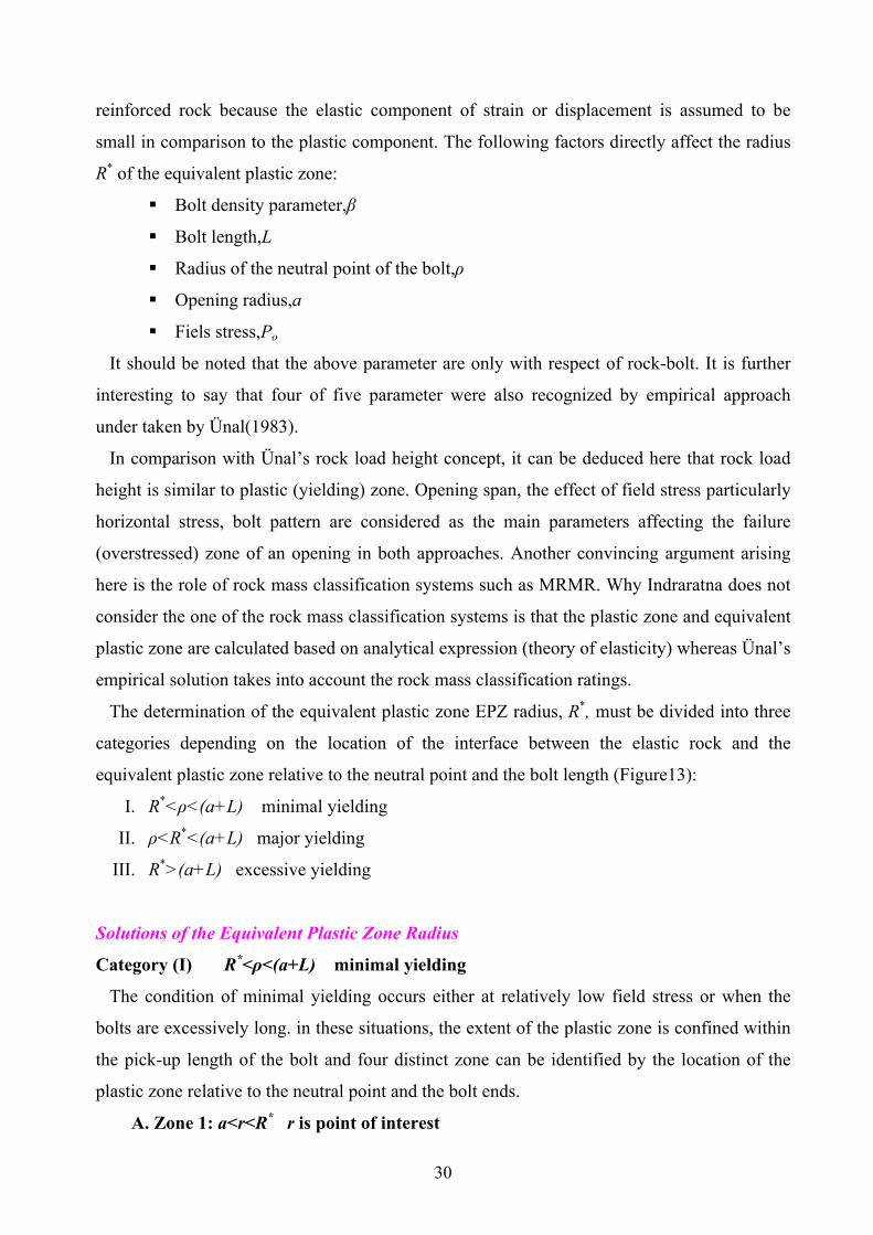
The determination of the equivalent plastic zone EPZ radius, R*, must be divided into three
categories depending on the location of the interface between the elastic rock and the
equivalent plastic zone relative to the neutral point and the bolt length (Figure13):
I. R*<ρ<(a+L) minimal yielding
II. ρ<R*<(a+L) major yielding
III. R*>(a+L) excessive yielding
Solutions of the Equivalent Plastic Zone Radius
Category (І) R*<ρ<(a+L) minimal yielding
The condition of minimal yielding occurs either at relatively low field stress or when the
bolts are excessively long. in these situations, the extent of the plastic zone is confined within
the pick-up length of the bolt and four distinct zone can be identified by the location of the
plastic zone relative to the neutral point and the bolt ends.
A. Zone 1: a<r<R* r is point of interest

31
Figure 13. Categorazation of the extent of yielding (after Intraratna, 1987)

32
In this region of the pick-up length, the ground displacements toward the opening are
resisted by positive shear stress. The equivalent stress field in this zone is represented by:
−
−=
−
∗
∗ ∗
11
1mc
r ar
msσ
σ (82)
∗∗ += cr sm σσσθ (83)
where
)1( β+=∗ mm and )1( βσσ +=∗cc
B. Zone 2: R*<r<ρ
This part of the elastic zone is confined to the pick-up length of the bolt. The elatic stress
fields in this zone are given by:
22*
1
+
−=
∗
rR
rR
rRor σσσ (84)
22*
1
−
−=
∗
rR
rR
rRo σσσθ (8)
the peak tangential stress, σθR, at the elasto-plastic interface for s=1 is given by the following
condition: ∗∗ += crRR m σσσθ
the radial stress at the elasto-plastic boundary σrR is derived by substituting r=R* in the latter
equations:
12 *
+−
= ∗mco
rRσσ
σ (86)
C. Zone 2: ρ <r<(a+L)
This part of the elastic zone is contained within the anchor length of the bolt. The radial and
tangential stress fields are given by:
22
1
+
−=
rrorρσρσσ ρ (87)

33
22
1
−
+=
rroρσρσσ ρθ (88)
where 2*2*
1
+
−=
ρσ
ρσσ RR
rRop (89)
D. Zone 4: r > (a+L)
This outermost elastic region, beyond the bolt, is in virgin rock and the elastic stresses are
given by:
22
1
+
+
+
−=r
Lar
LaLor σσσ (90)
22
1
+
−
+
+=r
Lar
LaLo σσσθ (91)
where 22
1
++
+−=
LaLaoLρσρσσ ρ (92)
the radial distance to the neutral point is given by Equation 50 ,as discussed earlier. At the
elastic-plastic interface, the assumption of continuity of radial stress gives
−
−
=+−
=−∗∗
111
2)1(
*
*
*
*mcco
rR aR
ms
mσσσ
σ (93)
the solution of above equation provides the normalized radius of the equivalent plastic zone
(EPZ): )1/(1
**
***
12
1111
−
−
+−
+=m
c
o
mm
saR
σσ (94)
It is obvious that as β tends to zero, the parameters m* and σc* approach m and σc. In other
word, above equation becomes identical to that of unsupported case as derived by Kaiser et
al(1985) i.e.
( ) )1/(1 *
)12
11( −+
−
+−
= m
c
co
smm
aR
σσσ (95)

34
As discussed above, for the category (І) the solutions are solved, in the same way solutions
for the categories (ΙΙ) and (ІІІ) are extractable. The condition of major yielding, ρ<R*<(a+L),
occurs when the extent of the plastic zone has propagated beyond the neutral point. In this
situation, the plastic zone itself is divided by the neutral point into two zones. Consequently,
only the plastic zone region that falls within the pick-up length of the bolt is effectively
stabilized by the positive shear stresses. The equivalent plastic zone radius is then given by:
)1/(1
1
1*
11
−′
+
′+=
m
AB
aaR ρ (96a)
where
−
′
+′−′
=′ 12
111
1c
o
mm
sB
σσ (96b)
−
−+
−−′
=−
111
11 )1(
*1
*m
ammA ρ
ββ (96c)
m=m(1-β) and σ΄c=σc(1-β) (96d)
The condition of excessive yielding, R*>(a+L), occurs either due to large in-situ stress in
relatively weak rock or as a result of inadequate bolt length. In this situation, the bolt is
completely embedded in the yielded rock and no anchorage is provided from the outer elastic
zone. The radius of the equivalent plastic zone is now given by:
)1/(1
32
1*
111
−
++
+
+=
m
AAB
aL
aR (97a)
−
+−
= 12
111
1c
o
mm
sB
σσ (97b)
−
+
−′−
=−′
111
)1(
2
mLa
mmA
ρ (97c)
( )
−
+
−−
+=−−′
1111
)1()1(
*3
*mm
aLa
mmA ρ
ρβ (97d)
)1(* β+= mm
)1( β−=′ mm (97e)

35
The strain and displacement fields are determined by the application of Hooke’s laws, strain
compatibility, flow rule and strain-displacement relationships as discussed earlier.
5.2.7. Discussion of behavior predicted by the analytical model
Evidence to support the analytical predictions has been obtained by laboratory simulations
of a model opening; accordingly, results in much interesting finding as briefly given
here(Indraratna 1987):
1. It was concluded that as the bolt density parameter β increases, the radial and
tangential stress fields approach those predicted for non-yielding, elastic rock, and the
radius of equivalent plastic zone (R*) approaches the opening radius. Further away
from opening, the stress field tends toward the far-field stress.
2. For the strain field, as the bolt density parameter β increases, the radial and tangential
strains approach the elastic solution. The pronounced reduction of the total tangential
strain(εθt) inside the overstressed zone at the elastic-plastic boundary indicates
strengthening of the yielding material by the bolts.
3. Regarding displacement induced, as the distance from the opening wall increases, the
effect of bolting on the radial displacement diminishes rapidly and the far field
conditions are approached. It is evident that the maximum decrease in strains and
radial displacements occurs at the opening wall. Hence, the opening wall convergence
can be considered as the most appropriate parameter for a displacement controlled
design approach.
5.2.8. Influence of grouted bolts on opening wall stability
The radial strains and displacements at the opening wall are the most fundamental quantities
required to evaluate the stability of a opening. In the field they are not only feasible to
measure but are also generally reliable. The radial strain and convergence of the reinforced
opening wall can be predicted from the following equations, after the magnitude of R* has
been determined for the respective categories I to III:
GaRs
aRM
Gcr
a
c
am
cra 2)1(1
2)1(
)1(*)(** νσ
σσναε −
−+
−
−−=
++
(98)

36
−+
−
+
−=
++ )1(*)(**
)1(112
)1(αα
σσνa
Rsa
RMGa
uc
m
cra (99)
where
)1(1 ν+=
EG
and
)1(sin12
−−+=
αφαM (100)
the derivation of the above expressions is based on the assumption that both radial
displacement and radial stresses are continuous across the elasto-plastic boundaries, regardless
of the field stress magnitude. In addition, the post peak parameters α and s are assumed to be
constant irrespective of the bolt density; whereas, the elastic parameters G and ν are
considered to be characteristic of the original intact material prior to yielding.
5.2.9. Use of displacement control approach for design
The dimensionless ratios R*/a and u*/a are both directly dependent on the bolt density
parameter β and normalized bolt length (L/a). If β is kept constant for a smaller opening
excavated in the same homogeneous and isotropic rock., the ratio u*/a is not affected if the
bolt length is also reduced proportionately(i.e. scaled reduction). However, if the bolt length
remains unchanged for a smaller opening radius, the quantity u*/a decreases for the same β. In
contrast, for a larger opening the bolt length must be increased accordingly in order to
maintain the same u*/a ratio for a given β.
The above predictions may not be accurate for a opening excavated in a predominantly
jointed medium. This is because; a larger opening intersects a greater number of
discontinuities, thereby adopting a behavior equivalent to that of an excavation in a weaker
medium.
The applicability of this philosophy was examined by Indraratna 1987 in details. By
knowing the properties of rock mass around the opening and post peak parameters of rock α
and s, one is able to calculate the extent of the yielding zone and predicted convergence of the
unsupported opening as discussed earlier. The next step is to use a bolt pattern with respect to
bolt density parameter. Since the bolt length isn’t included into bolt density parameter, we can
assess the stability based on either bolt density effect or bolt length effect. No matter which

37
treatment is applied, the extent of yielding zone as well as total opening wall convergence
decrease.
5.2.10. Normalized convergence ratio
The convergence of a reinforced opening can be presented by the dimensionless ratio ua*/ua,
where ua*and ua are the total convergence of the reinforced and unsupported opening
respectively at the same stress level. The total opening convergence includes both the elastic
and plastic displacements. For a given field stress, ua* is less than ua but it approaches ua when
the bolt density (β) or the bolt length (L) tends to zero.
The normalized convergence ratio decreases as the intensity of bolting increases. It obtains a
minimum value when ua* tends to ue, the elastic portion of the total convergence. The latter
condition may be approached at every intensive bolt densities such as β>.30, which is not
only rare in practice but is economically unattractive. The convergence ratio is particularly
useful in the design of grouted and swellex bolts, since it reflects the reduction in convergence
that can be achieved by a given bolt pattern.
An important characteristic of the convergence ratio is that it is insensitive to moderate
changes of the deformation and strength parameters. For instance, a change in Young’s
modulus affects both ua* and ua equally, hence the ratio ua*/ua remains unaltered. The latter
characteristic of the normalized convergence ratio makes its use in design even more reliable,
since the variation of in-situ geotechnical parameters can be tolerated without any significant
error.
5.2.11. Concept of bolt effectiveness
In order to assess the efficiency of bolting, the opening convergence is selected as the
appropriate evaluation criterion. Obviously, optimal efficiency of a bolt system corresponds to
minimal opening convergence that can be achieved within economic limitations. In reality, the
total convergence of a yielding, reinforced opening wall (ua*) must be less than of an
unsupported opening (ua), but more than the convergence predicted by the linear elastic
solution (ue). Considering these limitations the bolt effectiveness (i) for a given field stress is
best defined as:
%*
ea
aa
uuuu
i−−
= (101)

38
The bolt effectiveness (i) is sensitive to moderate changes in uniaxial compressive strength
and the friction angle. Therefore, its use as a design tool is justified only if the geotechnical
properties of ground are accurately determined.
5.2.12. Relationship between the analytical solution and rock mass classification
approach (empirical design)
No analytical solution, according to engineering judgment, is valid on the condition that it is
verified by empirical approaches. Rock mass classification is generally recognized the most
suitable way of designing the reinforcement system in a rational manner.
Amongst rock mass classification systems, the Bieniawski’s (RMR System) seems to be
applicable to fully grouted bolts in all types of rock. The deficiency of the Q-system for
defining an appropriate reinforcement system in the case of using the grouted bolt has been
discussed earlier .Unfortunately, Bieniawski didn’t offer any extra support design guideline
apart from that has been published in the literature.
According to Bieniawski’s guidelines (1974, 1979, 1989), the recommended bolt lengths (L)
and grid spacing (SL×ST) for different rock classes are tabulated in the first three columns of
Table2. The ratio β/λ for these rock classes can be deduced from this information and is
tabulated in the forth column. The magnitude of λ may be estimated from the effective bond
angle of the bolt/grout interface to determine β. The corresponding bolts density parameters
for an assumed λ=0.5 are given in the last column of Table 2. Several interesting aspects
evolve from this table. The bolt densities (β) recommended for poor to very-poor rock are
relatively insensitive to rock quality changes and the advocated range of β for some rock
classes (RMR< 40) is very wide.
According to surveyed conducted, for RMR<20, bolt densities seems to be too lower. Based
on results obtained from experiences, as the bolt density increases, so the spacing decreases.
Hence a reduction of the bolt spacing for a weakest rock class would provide a sufficiently
high magnitude for β to curtail displacements more effectively than by increasing the bolt
length. This finding is so important in that in the weak rock mass RMR<40, for instance at the
weak, stratified, clay bearing rock masses perfectly characterized by Ünal (1996), decreasing
the bolts spacing is far more effective than increasing the bolts length. This evidence was also
supported by Laubscher and Taylor who proposed bolt spacing less than 0.75m for poor
ground at RMR<30. This bolt spacing corresponds to a β-value of about 0.28 for λ=0.5, and

39
seems to be in good agreement with the densities proposed by Intraratna (1987,1990) for
effective convergence reduction.
In my opinion, on the basis of results and observations, I concluded that the RMR system
may not provide a sufficiently sensitive guide to properly designed grouted bolts, even all
types of fictitious bolt, in weak, yielding rock mass. For classes of poor rock (RMR<40), a
rational design method for grouted bolts should be based on an analytical approach, which
provides a sound basis for effective convergence control. However, for reinforcement system
guidelines fro RMR<40, it is wise to classify the rock mass based upon Modified Rock Mass
Rating (M-RMR) developed by Ünal (1996) and then in order to better characterize the rock
mass in terms of strength parameters, the M-RMR class of rock mass can be switched into
GSI (Geological Strength Index), leading ultimately to a new concept of empirical
reinforcement design, which satisfies analytical methods.
Table 2. Recommended bolt densities according to
Geomechanics Classification (RMR) (after Intraratna & Kaiser, 1990) Rock class L SL and ST β
RMR Condition (m) (m) β/λ (at
λ=0.5 )
81-100 Very good no support 0.00
61-80 Good 2-3 2.5 0.05 0.10
41-60 Fair 3-4 1.5 – 2.0 0.08 – 0.14 0.04-0.07
21-40 Poor 4-5 1.0 – 1.5 0.14 – 0.31 0.07 – 0.16
<20 Very poor 5-6 1.0 – 1.5 0.14 - 0.31 0.07 – 0.16
5.2.13. Discussion and verification of the analytical model
The development of load on a grouted bolt has the effect of providing additional
confinement (increased radial stress) in the yielded zone. As a result the tangential stress at the
same point is increased more than proportionately. The original failure envelope is thereby
shifted upwards, indicating an improvement of the apparent strength (σc, φ), as represented by
the Mohr-Coulomb diagram in Figure 14. This enables the rock mass to behave as a stronger
material leading to a corresponding reduction in opening convergence at a given field stress.
Owing to the fact that fully grouted bolts effectively improve the apparent strength of the
rock mass, the behavior of the reinforced opening can be ideally represented by a shift of the

40
ground convergence curve. The vertical axis of the ground convergence curve (Figure 15)
represents the fictitious radial stress (σs) required at the opening boundary to prevent further
convergence. The horizontal axis represents the opening convergence at the opening wall (ua).
The ground convergence curves are identical at every point along the opening boundary for
the condition of axisymmetric yielding under hydrostatic field stress.
Figure 14. Effect of grouted bolts on
failure envelope (after Intraratna, 1987,1990)
Figure 15. Effect of grouted bolts on
ground convergence curve ((after Intraratna, 1987,1990)
The response of an unsupported opening in yielding rock is given by curve A. curve B
represents an imaginary ground convergence curve of the opening, where bolts would have
been installed before any displacements could have occurred. In reality, an initial

41
displacement (uo) of the opening wall occurs prior to the installation and subsequent activation
of the grouted bolts. The magnitude of convergence after bolting is dependent on the apparent
stiffness of the bolt/ground composite, and is reflected by a shift of the ground convergence
curve from curve A to curve C, as a result of the reduced yield zone. In contrast to fully
grouted bolts, pre-tensioned mechanical bolts provide direct radial pressure (active support)
against the opening wall, but do not become an integral part of the deforming rock mass.
Consequently, their performance is best represented by a support confinement curve with a
specific stiffness and its interaction with the original ground convergence curve.
PART B: NON-LINEAR CONSTITUTIVE MODEL
USING ASSOCIATED FLOW RULE AND
EMPIRICAL HOEK & BRROWN YIELD CONDITION
In this part, constitutive models associated with passive rock-bolt systems are discussed
based on non-linear Hoek and Brown failure criterion using associated flow rule. Unlike
previous constitutive model, this model has been highly subjected to argue due to its
complexity. Since the Ph.D. study is concerned with passive rock-bolt systems (grouted and
swellex bolts) the Hoek and Brown solution (1980) corresponding to pre-stressed rock-bolt
design won’t be disputed here. Hoek and Brown (1980) introduced a solution containing
ground reaction and available support curves (convergence-confinement method) for a
circular opening at a hydrostatic field stress in a homogeneous, isotopic rock mass based on
theory of elasticity. They took their non-linear failure criterion, associated flow rule, and a
material behavior model prosecuting elastic-brittle –perfectly plastic into account. Based on
their solution, alternatively recommended support systems could be utilized in a variety of
rock mass conditions. Despite their sophisticated solution, no analytical model for passive
rock-bolt system and its interaction with rock mass could have been presented. However,
Hoek and Brown only pointed out that the support action of grouted rock-bolts would arise
from internal reinforcement of the rock mass in much the same way as the presence of
reinforcing steel acts in reinforced concrete. Up to that time, no direct evidence was available
on the strength of reinforced rock masses.
Oreste and Peila (1995.1996,1997,2003) introduced a design of passive rock-bolt systems
based on convergence-confinement concept. In my opinion, there have been some
inconveniences and uncertainties in their solution; however, the model they used is so
complex.

42
5.3.ORESTE & PEILA CONSTITUTIVE MODEL
Peila and Oreste (1995) presented a new convergence-confinement approach able to model a
reinforced rock mass zone surrounding an opening zone with new improved properties.
A circular opening subjected to an undisturbed hydrostatic stress field, under plane strain
conditions has been modeled (Figure 16). The rock mass has been considered homogeneous,
isotropic, elasto-plastic with a strain-softening material behavior and non-linear Hoek and
Brown yield condition both peak and residual parameters of failure criterion i.e. both m and s
decrease from the peak value to the residual ones linearly with the tangential strain.
It is at this point so interesting that for the first time, the strain-softening model was chosen
for modeling the reinforced rock mass around
an opening. Brown et al (1983), however, in an
outstanding article presented a new analytical
solution for a unsupported circular opening
following the previous solution of Hoek and
Brown (1980) modeling the rock mass in the
case of both elastic-brittle plastic and elastic-
strain softening. The problem has been solved
with the usual concepts applied in the
converegnce-cofinement approach using a
finite difference scheme (due to the
mathematical complexity of the describing
equation) because the differential equations
that describe the rock mass stress-strain field, with and without bolts, have been easily solved
by finite difference method (FDM). The mathematical solution follows the step-wise sequence
of calculations for an elastic-strain, softening-plastic model in which post-peak dilatancy
occurs at a lower rate with major principle strain in the constant strength plastic zone than in
the strain softening zone. The bolts are considered to be fully bonded to the rock and with
linear-elastic behavior. In this work it has been shown that small variations of the rock mass
mechanical properties (the peak and residual strength parameters, the elastic modulus and the
strain softening parameters) in the reinforced zone with respect to natural rock mass, influence
the opening deformations and the stresses induced in the rock mass.
Figure 16. Assumed opening geometry (after Brady & Beown, 1985).

43
This model is capable of taking the effect of the distance from the bolted section to the
opening face, the effect of increasing the lateral spacing between bolts (ST in Fig.17) and the
influence of different bolt end plate response
curves into consideration.
When the bolts are installed, a certain
convergence of the natural rock mass has
already developed (with respect to undisturbed
condition). This is modeled by reducing the
fictitious internal pressure from the Po value to a
percentage of this value (Panet and Guenot,
1982), according to the distance from the
opening face; a further reduction of the internal
pressure (simulation of the excavation process
(FLAC 4, 2000)) induces tensile forces in the
bolt which are applied to the rock mass through
the bolt lateral surface and the nut end-plate. Indraratna & Kaiser (1990) had mentioned that
relatively small displacements (4-5 mm) were normally sufficient to mobilize axial bolt
tension by shear stress transmission from the rock to the bolt surface. The force applied by the
bolt to the opening surface is strictly dependent on the nut end-plate stress-strain behavior.
The condition of ideal tie, which means zero flexibility of the nut end-plate, allows the bolt to
transfer the maximum force to the opening surface. In reality, however, even a lower bound
condition where zero force is applied to opening perimeter is not taken to account and an
intermediate condition is presented. The main steps of the analysis are as follows:
a. Computation of the convergence-confinement curve without bolts and stresses and
strains for an internal pressure Pin value between Po and the internal pressure of bolt
installation (Pinst) [Pinst<Pin<Po].
b. Computation of the convergence-confinement curve of a fictitious opening with a
radius equal to the real opening radius plus the bolt length [rfict=rin+Lb];
c. Computation of the real stress-strain field influenced by the presence of the reinforcing
elements starting from the values computed in step (b), for each point of the
convergence-confinement curve of the fictitious opening (displacement and internal
pressure), using a finite difference procedure. The value of the pressure and radial
Figure 17. Geometry of the axsisymmetric problem (after Oreste & Peila,1996).

44
displacement obtained at the opening radius are the real values of the bolted
convergence-confinement curve.
The final convergence-confinement curve is therefore obtained by considering the values
computed in step (a) for an internal pressure which varies from Po to Pinst, and the curve
computed in step (c) fro an internal pressure which varies from Pinst to zero.[0<Pin<Pint].
5.3.1.Rock mass behavior model
The strength criterion adopted is that proposed by Hoek & Brown (1980,2002): a
cibci sm
+
′+′=′
σσ
σσσ 331 (102)
where mb is a reduced value of the material constant mi and is given by:
−−
=D
GSImm ib 1428100exp (103)
s and a are constants for the rock mass given by the following relationships:
−−
=D
GSIs39100exp and
( )3/2015/
61
21 −− −+= eea GSI (104)
D is a factor which depends upon the degree of disturbance to which the rock mass has been
subjected by blast damage and stress relaxation. It varies from 0 for undisturbed in-situ rock
masses to 1 fro very disturbed rock masses. Guidelines for the selection of D are shown
elsewhere (Hoek et al. 2002).
It is assumed that the residual strength criterion is given the same analytical formulation,
where the parameters m and s refer to the residual values mr and sr.
A strain softening behavior is assumed in the plastic zone (Brown et al.1983). The f and h
parameters describe the magnitude of the plastic behavior after the peak condition (ratio
between the radial and tangential plastic strain both in the residual and softening branch of the
stress-strain curve), while α defines the width of the softening zone (see Figure 2).
Experimental data are required to determine these parameters (Brown et al.1983, Peila &
Oreste, 1995). The appropriate rock mass properties can be obtained by back-analysis of field
data and are based on the designer experience.
Peila and Oreste (1985) presented an analytical expression of f using associated flue rule of
the theory of plasticity corresponding to Hoek and Brown Failure Criterion:

45
12 1
+=+
−sorCm
mfσ
(105)
Brown, Bray, Ladanyi, and Hoek (1983) presented, as earlier mentioned, an analytical
solution for a circular opening in the case of strain-softening behavior of material which
allows for the non-linearly empirical Hoek & Brown failure criterion. In that case, the solution
must account for the possible existence of three different zones around the opening: (1) An
elastic zone remote from the opening; (2) an intermediate plastic zone in which the stresses
and strains fall on the strain-softening portion of Fig 2; and (3) an inner plastic zone in which
stresses are limited by the residual strength of the rock mass (see Figure 18). For non-
axisymmetric problems, comparable closed-form or iterative finite difference solutions cannot
be obtained, and a numerical method of computation, such as the finite element method
(FEM), must be used (Brady & Brown, 1985).
Figure 18. Plastic zone divided into thinannuli for finite difference solution (stepwise geometrical discretization) (after Brady & Brown,1985).
According to Figure 19, the zones around an opening can be defined based on the properties
of the rock mass. An unsupported opening, Pi=0, constitutes two major rock mass around
itself namely, broken (plastic or yielding) zone and elastic (natural) zone while a reinforced
opening is embedded within reinforced rock mass and elastic zone. What is by far important
to recognize is that how much the reinforced rock mass accounts for yielding zone. Intraratna
(1987) regarded the reinforced rock mass surrounded within yielding zone as equivalent
plastic zone (EPZ). The connection between those zones is of great importance in order to
better understand the behavior of reinforced rock mass.

46
With a assumption that a linear elastic stress-
strain behavior occurs before failure and use the
equilibrium equation (Equ. 51) and boundary
conditions u=0, εr=0, εθ=0, σr= 0 at r=∞ and σr=
σre (σre is the radial stress at failure) at the plastic-
elastic interface (re), stress and strain in the elastic
region will be:
3
2
)( )( σσσ =
−−=
rr
PP ebrkroor (106)
1
2
)( )( σσσθ =
−+=
rr
PP ebrkroo (107)
3
2
)(1)( ενσε =
+
−−=rr
EP e
brkror (108)
1
2
)(1)( ενσεθ =
+
−−=rr
EP e
brkro (109)
+−−=
rr
EPu e
brkror
2
)(1)( νσ (110)
at r=re the radial and tangential stresses (minor and maximum principal stresses) apart from
having to satisfy the elasticity theory, must also satisfy the adopted failure criterion: a
c
brkrbcbrkrbrk sm
++=
σσ
σσσθ)(
)()( (111)
where σθ(brk) is the tangential stress at failure.
Equation 111 may be rewritten, using equations 106 and 107:
( )acibrkrcibbrkro smP σσσσ +=− )()((2 (112)
from which, after some simplifications, one obtains:
ciobrkr MP σσ −=)( (113)
where
sPmmm
Mci
obbb ++
+−=
σ
2
45.0
8 and a is considered to be 0.5. (114)
It is therefore possible to define the strains at the elastic-plastic interface, from equations 108,
109 and 113:
Figure 19. studid problem scheme ( after Peila & Oreste, 1995).

47
EM cirr e
νσε +−=
1)( (115)
EM cire
νσεθ+
=1
)( (116)
The mathematical formulation proposed by Brown et al. (1983) has been utilized in order to
describe the stress-strain behavior of the rock mass in the plastic (strain-softening) zone, It is
assumed that both m and s decrease from peak values to the residual value mr and sr, linearly
with the tangential strain:
)(
)()1(
)1()(
)()1(re
rejmmmm rjθ
θθ
εαεε
−
−−+= +
+ (117)
)(
)()1(
)1()(
)()1(re
rejssss rjθ
θθ
εαεε
−
−−+= +
+ (118)
where m(j+1) and s(j+1) are the m and s values in the softening zone at a point where the
tangential strain is εθ(j+1).
On this basis, the value of re, the position of which has not yet been defined, is obtained
with a numerical solution based on the finite difference method. The computational procedure
involves the discretization of the plastic zone in annular rings starting from the unknown
elastic-plastic interface towards the opening, by incrementing the tangential strain value εθ(j)
for every calculation step and calculating the corresponding radial strain. Since, from the
above equations, at r=re, the radial stress, mb and s (peak value) are known, and by assuming
that the tangential and radial strain are continuous the following can be written:
)()()( orbrkrr reσσσ == (119)
)()( ore mm = (120)
)()( ore ss = (121)
)()()()(
2orerere crcibr sm θθ σσσσσσ =++= (122)
)()( ore rr εε = (123)
)()( ore θθ εε = (124)
while for ring (j+1), which lies between the radii r(j+1) and r(j), the strains at the boundaries are
defined by:

48
)(5.05.0 )1()()1()()1()(
)1()(
)1(
)1(+
++
+
+
+ +=
+
≅
−−
=∆∆
jrjrjjjj
jj
j
j
drdu
drdu
rruu
ru
εε
which, since
)()(
)(i
j
j
ru
θε−= and )1(
)1(
)1(+
−=+
+j
j
j
ru
θε ,
can be written as:
)1()()1(
)1()()(
)(
)1(
)(
)1(
22
++
+++
−−−−
==jrjrj
jrjrj
j
j
j
j
rr
εεεεεε
λλ
θ
θ (125)
where: λ(j+1) and λ(j): ratio between the radius r(j+1) or r(j), and the unknown value of re; the
tangential strain at r(j+1), εθ(j+1), is imposed by assuming an arbitrary incremental value at r(j) is
known.
The stresses at the boundaries, for ring (j+1), are defined by:
)(5.0
)).(5.0(
)(5.0
)1()(
2)1()()1()1(
)1()(
),1(),1(
)1()(
)1()(
)1(
)1(
+
+++
+
++
+
+
+
+
+
++=
+
−≅
−
−=
∆
∆
jj
cijmedcijrjrjmed
jj
medjrmedj
ji
jrjr
j
jr
rr
sm
rrrrr
σσσσ
σσσσσ θ
(126)
where,mmed(j+1),smed(j+1): average strength parameters. After some substitution equations 125,
126,and 128 allow one to define the radial and tangential stresses at the linear surface of ring
(j+1):
Abbjr −−=+2
)1(σ (127)
where:
)5.0(4 2)()()()( cjmedjrcijmedr smkA
jσσσσ +−=
cijmedjr kmb σσ )()( +=
2
)1(
)1(
2
)1()(
)1()(
11
+
−=
+
−=
+
+
+
+
j
j
jj
jj
rrrr
kλλ
2)1()1()1()1()1( cijjrcijjrj sm σσσσσθ +++++ ++= (128)
By carrying out the iteration from the unknown value of the plastic radius and by calculating
the value of λ(j+1) for each iteration, the plastic radius, for a defined internal pressure Pin,
results to be:

49
∑ = +
= =+ n
j j
ipe
rrjrin
0 )1(
)( )1( λσ (129)
where n is the total number of iteration. The problem is solved computing σr(j+1), ur(j+1) and
re(j+1) for each calculating ring.
5.3.2. Reinforced rock mass and grouted bolt behavior simulation
When the reinforcing elements are to be accounted for, the equilibrium equation, as shown
in Figure 20, must be rewritten as:
rSSr
drdT
drd
TL
i
r
rr 1+
−=
σσσσ θ (130)
where:
SL= longitudinal bolt spacing along the opening axis;
STo= transversal bolt spacing on the opening perimeter;
r = distance between the considered point in the rock mass and the opening axis;
T = axial tensile force in the bolt at a distance r, from the opening axis;
Assuming that the principal stress directions are
not affected by the bolts, and that there is no
adherence loss between the bolt and the rock mass,
the axial force in the bolt (T) depends upon the
radial strain in the rock mass, which is developed
following bolt installation:
)( rrbb AET εε −−= (131)
where εr is the radial strain in the rock mass at a
distance r from the opening axis, εr is the radial strain in the rock mass at the same distance r
when the bolt is installed, Eb is the Young’s modulus of the bolt and Ab is the bolt transverse
section.
The numerical calculation procedure used for the simulation of the plastic natural rock mass,
described in the previous paragraphs, is now applied both in the elastic and plastic conditions.
Starting from the known values of the convergence-confinement curve of the fictitious
opening (at rfic) the calculation rings develop towards the opening perimeter until rock failure
occurs. Equations 106 to 110 are now substituted by equations 133 to 136, written in a finite
Figure 20. Stresses in the bolt and in the rock mass(after Oreste &Peila,199).

50
difference form, for a distance r(j+1) from the opening axis. r(j+1) is defined by equation 132
and depends on the incremental value of the tangential strain.
ξξ
⋅⋅⋅−+−
=+ 242
)1(ztt
r j (132)
)()( )1()1()1()1()1()1( ++++++ −+−+= jrjrjjjrjr cq εεεεσσ θθ (133)
)()(1)1()1()1()1()1()1( ++++++ −+−+= jrjrjjjj q
eεεεεσσ θθθθ (134)
( ) ( )[ ] ( ) ( )[ ])()1(
)()()()()(
)()1(
)()()1()1()1()1()1(
22
jj
jrjrjjj
jj
jrjrjjjjrjr rr
rrr
r−
−−−−
−
−−−+=
++
+++++
εεεεεεεεεε θθθθ (135)
)1()1()1()1()1( )( +++++ −−= jjjjj ruu θθ εε (136)
where:
EE
EEE
e
b
2
22
3
22
1)(1
ν
νννν
−
+
−
+−=
eEE
E
EE
c
bb
22
22
211
1
−
+
+−
=ν
νν
ν
;2cqn −= ;1 2
2
eEE
Eq
b
−
+
=ν
νν
e
qn 122 −+−=γ
[ ])()(2
)()22()(2)(2
)()()()()(
)()()()()()()1()1()(
jrjrjjj
jrjrjjjjjjj
r
rqcnrre
t
σσσσ
εεεεεε
θθ
θθθθ
−−−
+−−+−+−= ++
)()()( )()()()()1()1( jjjrjrjj n θθθθ σσεεεεγξ −−−+−= ++
).()()(2)(1)(2 )()()()()()()1()1()()(2
)( jjjrjrjjjjjrjrj qqe
rz θθθθθθ σσεεεεεεσσ −−
−+−−−−−= ++
The over-lined variables in equations 132 to 136 refer to the stress-strain field in the rock-
mass at the moment of the bolt installation, i.e. Pin=Pinst..

51
The plastic radius in the reinforced rock mass (for internal pressures lower than the fictitious
pressure Pinst is now known before the simulation of the plastic zone is started (i.e. the radius
for which the tangential stress defined in the elastic field by equation 133 is greater than the
tangential stress defined by the strength peak condition).
The axisymmetric equilibrium with bolts (Equ. 130) is expressed in a finite difference form
for a generic ring by below equation:
)(21
1
)(21
)(21)(
21
)1()()1()(
)1()(
)()1(
)()1()()1(
)()1(
)()1(
++
+
+
++
+
+
+××
−
−+
+
+−+=
−
−
jjTL
i
jj
jj
jj
jrjrjj
jj
jrjr
rrSSr
rrTT
rrrr
σσσσσσ θθ(137)
and from the Hoek and Brown failure criterion:
2)()1()()1()()1( )(
2)(
21)(
21
ciacijrjra
jrjrjj sm σσσσσσσσ θθ ++=+−+ +++ (138)
one can obtain:
)(21
1
)(21
)(2
)1()()1()(
)1()(
)()1(
2)()1(
)()1(
)()1(
++
+
+
+
+
+
+⋅⋅
−
−+
+
+⋅+=
−
−
jjLT
i
jj
jj
jj
ciacijrjra
jj
jrjr
rrSSr
rrTT
rr
sm
rr
σσσσσσ (139)
where
[ ])1()(21
++= jja mmm and [ ])1()(21
++= jja sss .
For the reinforced rock mass equation 126 is substituted by equation 139. Assuming the
same geometrical discretization used for the solution of the stress-strain field in the natural
rock mass for an internal pressure equal to Pinst, equation 127 is substituted by equation 140.
lhhjr −−=+2
)1(σ (140)
where ησσ kmkh ciair 2)( −+=
−++−= χησσσσσ )(
2)()(
2
24 irciacijr
ajr smkl
TLjj
ijjjj
SSrrrTTrr
2)1()(
)1()()1()(
)())((
+
++
−
−+=η
22
)1()(
)1()(
−
−=
+
+
TL
i
jj
jj
SSr
rrTT
χ

52
having assumed the same previously described discretization of the natural plastic rock mass,
the r(j+1) value is known for each calculation ring.
From the radial and tangential strains continuity it is then possible to rewrite equation 125
where the radial and tangential strains at the inner surface of the considered annulus
(respectively, εr(j+1) and εθ(j+1)) are unknown. Since an increment of the tangential strain, in the
plastic zone, produces an increment of the radial strain [equation (141a) in the plastic residual
zone and equation (141b) in the softening zone], equation (125) can be solved as follows:
)( )()1()()1( jjjrjr f θθ εεεε −−= ++ (141a)
)( )()1()()1( jjjrjr g θθ εεεε −−= ++ (141b)
[ ]f
f
jjj
jrjjjjjjj )(2
)(2(2
)()1()1(
)()()1()()()1()()1( λλλ
ελλελλλε θθ −+
−+−+=
++
+++ (142a)
[ ]g
g
jjj
jrjjjjjjj )(2
)(2(2
)()1()1(
)()()1()()()1()()1( λλλ
ελλελλλε θθ −+
−+−+=
++
+++ (142b)
where f and g are the parameters in the plastic zone. When the radial strain εr(j+1) at r(j+1) is
known, it is possible to calculate the axial force in the bolt T(j+1) (Equ. 131) , the radial stress
in the plastic reinforced rock mass (Equ.140 ) and the corresponding tangential stress.
Therefore, the problem is completely solved.
6. CONCLUSIONS
In an effort to present a new constitutive model of rock-support interaction analysis, a
comprehensive literature survey on that topic was conducted. To date, four constitutive model
of rock-support interaction theory have been developed based on stress-strain behavior and
yield condition disciplines. While Stille’s approach and Indraratna & Kaiser’s analysis are in
conjunction with elastic-brittle plastic stress-strain relationship and linear Mohr-Coulomb
failure Criterion, Hoek & Brown and Oreste & Prila analyses are governed by non-linearly
empirical failure criterion. The rock-support solution undertaken by Hoek & Brown for
prestressed rock bolts in the case of elastic-brittle-plastic model of material is disregarded in
this study. For the first time, in order to develop an accurate and reliable roc-support
interaction analysis, the elastic-strain softening behavior of rock taken into account by Oreste
& peila, however, there are some uncertainties and inconveniences in their theory due to its
complexity of mathematical operations.

53
The author suggests enhancing the Indraratna & Kaiser’s solution because their model is
simple and back analysis of some physical models and two-site application showed a good
agreement between measured data and their solution. The following deficiencies of
Indraratna & Kaiser’s solution were recognized while comparing with the other models:
- Linear yielding criterion
- Elastic-brittle-plastic stress-strain law
- Same elastic modulus in the reinforced zone and in the natural rock mass
- Only the strength of rock mass is reduced to the residual value regardless of
considering the internal friction angle of rock mass.
If Indraratna & Kaiser’s constitutive model is mingled and modified with strain-softening
behavior of material as well as non-linear yield condition, a competitively precise model with
the minimum assumptions would be achieved.
7. REFERENCES 1. Personal communication with Prof.Dr.
Ünal (2003). 2. Barton, N., R. Lien and J. Lunde. (1974).
Engineering classification of rock masses for the design of tunnel support, Rock Mechanics, 6(4): 183-136.
3. Bieniawski,Z.T. (1989).Engineering Rock Mass Classification, John Wiley and Sons. New York.
4. Stille, H. (1983). Theoretical aspects on the difference between prestressesd anchor bolt and grouted bolt in squeezing rock. Proceedings of the International symposium on Rock Bolting. Edited by: O.Stephansson, Abisko, Sweden.pp65-73.
5. Stille, H., Holmberg, M. and Nord, G. (1989). Support of weak rock with grouted bolts and shotcrete. Int. J. Rock Mechanics and Mining Science & Geomechanics Abstracts. Vol 26. No. 1.pp 99-113.
6. Indraratna, B.(1987). Application of fully
grouted bolts in yielding rock. Ph.D thesis, University of Alberta.
7. Indraratna, B., Kaiser. P. K.(1987).Wall convergence in tunnels supported by fully grouted bolts. 28th U.S.Symp.on Rock Mech., Tuscon, Arizona, pp.843-852.
8. Indraratna, B. & Kaiser, P. K. (1990).Analytical model for the design of grouted rock bolts. International Journal for Numerical and Analytical Methods in Geomechanics. Vol 14. No.4, 227-251.
9. Indraratna, B. & Kaiser. P. K. (1990). Design for grouted rock bolts based on the convergence control method. Int. J. Rock mech. Mining Sci. & Geomech. Abstr. 27, 269-281.
10. Indraratna, B. (1993). Effect of bolts on failure modes near tunnel openings in soft rock. Geotechnique. Vol 43. No 3. 433-442.
11. Freeman. T. J. (1978). The behavior of fully-bonded rock bolts in the Kielder experimental tunnel. Tunnels & Tunneling 10,pp.37-40.
12. Ward. W. H., Tedd. P.and Berry. N. S. M. (1983). The Kielder experimental tunnel: final results. Géotechnique 33, No. 3, pp. 275-291.
13. Kaiser, P. K., Guenot, A. & Morgenstern, N. R. (1985). Deformation of small tunnels. Part 4: Bahavior during failure. Int. J. Rock mech. Mining Sci. & Geomech. Abstr..22, 141-152.
14. Oreste, P. P. & Peila, D. (1996). Radial passive rockbolting in tunnelling design with a new convergence- confinement

54
model. Int. J. Rock mech. Mining Sci. & Geomech. Abstr. 33, 443-454.
15. Peila, I. D.& Oreste, P. P.(1995). Axisymmetric analysis on ground reinforcing in tunneling design. Computers and Geotechnics. Vol 17. 253-274.
16. Peila. D., Oreste. P. P., Pelizza. S. (1997). Influence of face plate behavior on bolt support action. Int. Symp on Rock Support applied solutions for underground structures, Lillehammer, Norway.pp 296-306.
17. Oreste. P. P. (2003). Analysis of structural interaction in tunnels using the covergence–confinement approach. Tunnelling and Underground space Technology.(in press).
18. Brown, E. T., Bray. J. W., Landanyi. B. and Hoek. E. (1983). Ground response curves for rock tunnels. J. Geothechnical Engng .109, 15-39.
19. Brown, E.T. and Bray, J.W. (1982).
Rock-support interaction calculations for pressure shafts and tunnels. In Rock Mechanics: Caverns and Pressure Shafts (ed. W. Wittke) 2, pp. 555-565. Rotterdam: Balkema.
20. Asef, M. R., Redddish, D. J., Lloyd,
P.W. (2000). Rock–support interaction analysis based on numerical modeling. Geotechnical and Geological Engineering 18: 23–37.
21. Zhen Yu, T & Jie Xian, C. (1983). Behavior of rock bolting as tunneling support. Proceedings of the International symposium on Rock Bolting. Edited by: O.Stephansson, Abisko, Sweden.pp 87-92.
22. Xueyi, S. (1983). Grouted rock bolt used in underground engineering in soft surrounding rock or in highly stressed regions. Proceedings of the International symposium on Rock Bolting. Edited by: O.Stephansson, Abisko, Sweden.pp93-99.
23. Florence, A, L. & Schwer, L, E. (1978). Axisymmetric compression of a mohr- coulomb medium around a circular hole.
International journal for numerical and analytical methods in geomechanics, Vol. 2, 367-379.
24. Ünal, E. (1983). Development of design guidelines and roof control standards for coal mine roofs. Ph.D.Thesis, Penn State Univ., 355pp.
25. Ünal, E. (1996). Modified rock mass classification: M-RMR system. Milestone in Rock Engineering: A Jubilee Collection; Z. T. Bieniawski, Editor; Balkema, 203-223.
26. Hoek, E. & Brown, E. T. (1980).
Underground excavation in rock. IMM. London.527pp.
27. Hoek, E., Kaiser, P.K. and Bawden, W.F. (1995). Support of underground excavation in hard rock, A. A. Balkema.
28. Brady, B.H.G. and Brown, E.T. (1985). Rock mechanics for underground mining. London. Allen and Unwin.
29. Atlas Copco Rock Drills AB. (1998).Numerical approach for evaluation of tunneling supported by swellex rock bolt. Japan construction method and machinery research institute.
30. Hoek, E. and Brown, E.T. (1980). Empirical strength criterion for rock masses. J. Geotech. Engng Div., ASCE 106 (GT9), 1013-1035.
31. Hoek, E., Carranza-Torres, C.T., and Corkum, B. (2002). Hoek-Brown failure criterion –2002 edition. Proc. North American Rock Mechanics Society meeting in Toronto in July2002.
32. FLAC (Fast Lagrangian Analysis of Continua) V.3.2. User’s manual.(1993). ITASCA Consulting Group, Minneapolis, Minnesoat.USA.