Embed Size (px)
Citation preview

Hermann Kaps Bremen 20 May 2013
Page 1 of 64
Securing cargo for the road – the facts
Contents
Preface .................................................................................................................................................... 2 Introduction .............................................................................................................................................. 2 1. Tie-down lashing ........................................................................................................................... 4
1.1 Essentials of tie-down lashing ................................................................................................... 4 1.2 Traditional assessment models ................................................................................................ 5 1.3 Attempted improvements in EN 12195-1:2003 ......................................................................... 8
1.3.1 Physical basis for the k factor ............................................................................................ 8 1.3.2 The k factor in a tie-down lashing ...................................................................................... 9 1.3.3 Mathematical models used in DIN EN 12195-1:2004 ........................................................ 9 1.3.4 The standard tension force STF ........................................................................................ 10 1.3.5 Use of the friction between the lashing equipment and the cargo ................................... 14
1.4 Actual securing effect of a tie-down lashing ........................................................................... 15 1.4.1 Pre-tensioning forces in the initial situation ..................................................................... 15 1.4.2 Changes to the lashing lengths and lashing angles ........................................................ 16 1.4.3 Elasticity of lashing belts .................................................................................................. 19 1.4.4 Securing force in a lateral direction relative to the vehicle .............................................. 20 1.4.5 Securing force in a longitudinal direction relative to the vehicle ...................................... 23 1.4.6 Securing moment in a lateral direction relative to the vehicle ......................................... 26 1.4.7 Securing moment in a longitudinal direction relative to the vehicle ................................. 29 1.4.8 Influence of the coefficient of friction between the lashing material and the cargo ......... 33
1.5 Practical implementation ......................................................................................................... 37 1.5.1 Simplified assessment models ........................................................................................ 37 1.5.2 Coefficient of friction between the loading surface and the cargo ................................... 38
2. Direct securing ............................................................................................................................ 44 2.1 Necessary movement of the cargo ......................................................................................... 44
2.1.1 Lashing devices ............................................................................................................... 45 2.1.2 Blocking devices .............................................................................................................. 48
2.2 Permitted pre-tensioning force for a direct lashing ................................................................. 48 2.3 Securing effect of a direct lashing arrangement ..................................................................... 50
2.3.1 Effect against horizontal movement (displacement, deformation) ................................... 50 2.3.2 Effect against tipping ....................................................................................................... 51
2.4 Static indeterminacy with complex direct securing scenarios ................................................. 51 2.4.1 Different lashing angles and lengths................................................................................ 52 2.4.2 Different securing materials ............................................................................................. 53
3. Miscellaneous ............................................................................................................................. 55 3.1 Rolling factor ........................................................................................................................... 55
3.1.1 Physical causes ............................................................................................................... 55 3.1.2 Problems with acceptance ............................................................................................... 56
3.2 Tipping test .............................................................................................................................. 58 3.2.1 Equivalence to mathematical models .............................................................................. 58 3.2.2 Practicability ..................................................................................................................... 59 3.2.3 Enhancement for any vertical accelerations .................................................................... 60
4. Summary .................................................................................................................................... 61

Hermann Kaps Bremen 20 May 2013
Page 2 of 64
Preface
The report "Securing cargo in road transport – Who knows the truth?", which was published here in May 2010 was met with lively interest, but at the same time triggered considerable demand for clarification. The facts published here are intended to provide answers to the most important questions and perhaps provide assistance in achieving a common interpretation of DIN EN 12195-1. Ideally, such an interpretation would be in harmony with the recently reworked VDI Guideline 2700, Part 2 and the CTU Code due to be published by the IMO.
The EN 12195-1:2010 standard has now been recognised by ADR 2013 as the accepted basis for securing hazardous goods and is used throughout the Federal Republic of Germany for this purpose. On the other hand, the majority of the regional police authorities in Germany inspect the securing of non-hazardous cargoes on the basis of DIN EN 12195-1:2004, which is evidently stricter. This state of affairs alone is paradoxical in the eyes of all practitioners and needs to be clarified and, where necessary, rectified.
Introduction
What are the minimum requirements that need to be met by regulations governing the securing of cargo? This question is of concern to a very wide range of people, who will not be listed here. The answers are multi-faceted and driven by varying expectations.
1. According to the German road traffic regulations StVO §22 (1): The cargo, including any equipment and devices for securing the cargo, must be stowed and secured in such a way that it cannot slide, tip over, roll back and forth, fall from the vehicle or cause avoidable noise even in the event of an emergency braking manoeuvre or sudden avoiding action. Accepted technical rules and regulations must be observed.
2. According to ADR 2013: Packages containing dangerous substances and unpackaged dangerous articles shall be secured by suitable means capable of restraining the goods (such as fastening straps, sliding slat boards, adjustable brackets) in the vehicle or container in a manner that will prevent any movement during carriage which would change the orientation of the packages or cause them to be damaged.
3. The customers of a carrier, and in particular the consignees and the insurers of the consignment, wish to have any cargo secured in a manner that goes beyond the legal requirements of any national road traffic regulations or the ADR to the extent that both mechanical and climatic damage to the cargo are always avoided.
As far as the practical implementation of cargo-securing measures is concerned and when carrying out police inspections, it is necessary to rely on "accepted technical rules and regulations". In addition to notes on how securing should be performed, these rules also include mathematical test criteria that assess the balance between defined loads and stresses that arise during transportation on the one hand, and the effectiveness of the selected manner of securing the cargo on the other. Such assessments and their results are based on vastly simplified mathematical models, and it must not be assumed that these models offer an entirely accurate or complete reflection of reality either with respect to the loads and stresses experienced or with respect to the effectiveness of the securing. This has already been dealt with comprehensively in the report "Securing cargo in road transport – Who knows the truth?".
An exact representation of the physical reality using the mathematical models described is hardly feasible; indeed, the huge variety of factors that play a role means that it is not even an appropriate goal. Rather, the objective is to make the model used simple and universally applicable, while at the same time ensuring that the objectives and requirements listed above can be achieved without an excessive amount of effort. The wide range of factors that play a role means that it is only possible to determine whether a mathematical model meets these

Hermann Kaps Bremen 20 May 2013
Page 3 of 64
requirements after a period of several years and careful analysis of accidents. The simple fact that accidents still occur is not, on its own, an indicator of the model's technical suitability, because accidents are often demonstrably the result of a failure to comply with the model.
The table below shows an overview of the mathematical models that are currently regarded as being necessary.
Longitudinal sliding
Transverse sliding
Longitudinal tipping
Transverse tipping
Tie-down lashing (TDL) TDL Long. S TDL Tran. S TDL Long. T TDL Tran. T
Direct lashing (DL) DL Long. S DL Tran. S DL Long. T DL Tran. T
Up to now, calculations have taken virtually no account of compaction in the form of strapping or bundling individual cargo units or covering bulk cargo. The effectiveness of any combination of tie-down lashing or direct lashing with blocking measures is checked by simply adding together the securing effects. Checks with respect to the longitudinal axis make a distinction between two directions: in the direction of travel and against the direction of travel. This is because it is assumed that the corresponding loads experienced during transportation are different. Tie-down lashings are generally regarded as a number of lashings passed over the cargo transverse to the vehicle and which are attached to both sides of the vehicle, but are pre-tensioned on one side only.
Interpretation of vastly simplified mathematical models sometimes results in misunderstandings. Thus, for example, the currently accepted technical rules and regulations regard a tie-down lashing as adequate to withstand a load in the direction of travel if the
inertial force of the cargo FX = 0.8 m g is equal to or less than the friction between the
cargo and the vehicle FR = (m g + FV).
0.8 m g (m g + FV)
At this point it is uncertain whether the coefficient of friction for static friction or dynamic
friction should be used and how the total of all the vertical pre-tensioning forces FV of the tie-down lashings should be arrived at. This is purely a question of calibrating the model so that the result is able to stand for the complex physical reality. It is therefore wrong to use the mathematical model to conclude that a tie-down lashing checked against it will necessarily be able to withstand an emergency braking manoeuvre involving a deceleration force measured at 0.8 g without the cargo sliding (referred to here as "displacement") or becoming deformed. In the same way, the fact that the cargo is expected or observed to slide during an emergency braking manoeuvre despite being lashed down should not be taken to mean that the coefficient of dynamic friction should necessarily be used in the mathematical model.
Simplified mathematical models can be calibrated by means of statistical analysis of a considerable number of large-scale, systematic trials. However, this is an expensive undertaking that has never been put into practice. An alternative approach is to carry out comprehensive physical analysis of the load mechanisms on the basis of a small number of trials. It is possible that there is already a significant amount of material available. In fact, however, the preferred approach in the past appears to have been to assess proposed mathematical models on the basis of "previous practical experience" and it is unavoidable that economic considerations will also have played a role. Nevertheless, after a number of years have elapsed, it is somehow possible to assess the suitability of a mathematical model retrospectively.

Hermann Kaps Bremen 20 May 2013
Page 4 of 64
1. Tie-down lashing
1.1 Essentials of tie-down lashing
As a way of securing cargo, the tie-down lashing is undoubtedly archaic, as cargo such as bales, barrels, jars and perhaps wooden crates that used to be transported on horse-drawn carts hardly lend themselves to being secured directly.
This towering load of hay being transported on a wagon (Figure 1) provides an impressive demonstration of the tie-down lashing technique. The pole lying along the length of the hay is held down by two diagonal chains at each end. In addition, there are at least three ropes used as tie-down lashings across the load of hay. If we take a closer look, this arrangement of securing equipment covers virtually all the crucial aspects needed for a good tie-down lashing:
- The hay is compacted, and its elasticity ensures that the pre-tensioning forces on the chains and lashing ropes are high and remain so. With rigid cargo units, this role is nowadays fulfilled solely by the lashing equipment, which is why it must have an adequate degree of elasticity and must be capable of being re-tensioned.
- The long pole ensures that the load exerted by the vertical securing forces is distributed well along the length of the cargo and prevents the lashing ropes from cutting into the cargo too deeply. Nowadays, with soft loads such as this, edge protectors fulfill the same function, although they are sadly often not present.
- The lashing ropes achieve another desirable side effect, namely that they compact the load of hay. And today, this remains an important subsidiary function of a tie-down lashing.
Figure 1: Hay wagon with the load secured by tie-down lashings, http://kleinsthof.de
There are many aspects to the securing effect of a tie-down lashing applied at right angles to the vehicle axis. The effect can be broken down into the following elements:
1. The vertical components of the lashing forces increase the friction between the cargo and the loading surface, but also between horizontal layers of the cargo, and thus secure the cargo against shifting horizontally. This effect applies in all directions, i.e. longitudinally and laterally, but presupposes that the pre-tensioning force in the tie-down lashings is permanently present and that there is an adequate coefficient of friction.
2. If an external force is applied transversely to the vehicle axis, the cargo will shift slightly to the side. This can take the form of displacement (sliding) or deformation. With inclined tie-down lashings, the friction between the lashing equipment and the cargo results in a

Hermann Kaps Bremen 20 May 2013
Page 5 of 64
small, transverse securing component, which comes from the difference between the forces in the parts of the tie-down lashing. In a strictly vertical tie-down arrangement, both parts of the lashing will provide a transverse securing component. In the transitional region between an inclined and a vertical tie-down arrangement, both these effects occur concurrently.
3. If an external force is applied longitudinally along the vehicle axis, the cargo will shift longitudinally slightly. Both parts of a transverse tie-down lashing, whether inclined or vertical, are then inclined longitudinally and gain a small longitudinal securing component, whose magnitude is restricted by the friction between the cargo and the lashing equipment.
4. A tie-down lashing increases the stability in all directions of cargo units at risk of tipping, because the sum of the vertical components of the lashing forces can be added to the dead weight of the cargo, thus increasing its stabilizing moment. This simplified approach, however, only applies under symmetrical conditions. If the lashing equipment is arranged asymmetrically with respect to the centre of gravity of the cargo or to the effective tipping axes, each of the lashing forces must be included separately in the calculation.
5. If an external force is applied transversely to the vehicle axis, a cargo unit that is at risk of tipping will shift sideways slightly or even start to tilt a little. As a result, the geometry changes a little and becomes more favourable so that small, additional moments are generated that increase stability.
6. If an external force is applied longitudinally along the vehicle axis, a cargo unit that is at risk of tipping will shift longitudinally slightly or even start to tilt a little. Both parts of a transverse tie-down lashing then act as a direct lashing to prevent tipping. In this case, the maximum load that can be absorbed is determined by the lashing capacity LC. This relatively large force is, however, only achieved after the lashing equipment has stretched, which would in turn result in a significant amount of tilting involving additional dynamic effects. For this reason, the lashing capacity LC should not be used as a parameter in the model.
7. The various ways in which the cargo moves as listed above may possibly lead to a small degree of elastic stretch in the lashing equipment and hence to an increase in the forces. This increases the effects described under points 1. through 6. above.
8. If several cargo units are standing next to each other or stacked, a tie-down lashing acts to compact the cargo. If, however, there were initially gaps in the cargo, this can also lead to a reduction in the pre-tensioning force in the tie-down lashing. This highlights the importance of employing tensioners that allow the lashing equipment to be re-tensioned and of actually doing so during transportation.
9. Elastic tie-down lashings damp vertical vibrations of the cargo that can be caused by unevenness of the road. It is therefore important to use at least two tie-down lashings, even if friction alone appears to be sufficient to secure the cargo.
The complex mechanisms that govern the way in which these forces act mean that they cannot be represented with simple mathematical formulae. Indeed, they cry out for a simplified mathematical model to be developed that nevertheless encompasses the totality of all the effects. In the past, this has clearly only been achieved to a limited and insufficient extent.
1.2 Traditional assessment models
The traditional assessment model for tie-down lashings as described, for instance in the German VDI 2702 Guideline issued in May 1990 only makes use of the effects described in points 1. and 4. in the previous section. Thus, only the increase in friction resulting from the sum of the vertical components of the lashing forces is taken into account as having an effect

Hermann Kaps Bremen 20 May 2013
Page 6 of 64
to secure the cargo against sliding. In the same way, the securing effect against tipping is taken to be the sum of the vertical components of the lashing forces that increase stability. Expressed mathematically, the balances are as follows:
Sliding balance: )sinFn2W(Wf T (1)
Tipping balance: )sinFn2W(bWfa T (2)
f = coefficient of acceleration (0.8 to the front, 0.5 to the rear and to the sides) W = weight of the cargo to be secured [daN]
= coefficient of friction between the cargo and the loading surface n = number of tie-down lashings FT = pre-tensioning force in the tie-down lashing [daN]
= vertical lashing angle [°] a = lever of tilting moment [m] b = lever of stability moment [m]
FT FT
fW
a
b
tipping axis W
Figure 2: Traditional assessment of a tie-down lashing
These two models have two invaluable advantages. They are equally applicable to the longitudinal and transverse directions with respect to the vehicle and they do not rely on evaluating the effects of small movements of the cargo. The securing effects derived from small movements in the cargo, which taken together are considerably smaller than the primary effect of increasing friction, are not taken into account.
Of course, one could take the view that the cargo should not move anyway. This would, however, be inconsistent, because the traditional mathematical models for assessing direct securing arrangements imply a significant amount of cargo movement in order to exploit the full lashing capacity LC of the securing equipment (see Chapter 2). Furthermore, trying to compensate for a disequilibrium of forces or moments without any movement of the mass involved would contradict the laws of mechanics. Cargo that has been secured with tie-down lashings is permitted to move when subjected to an external load and, as shown in all trials, it duly does so.
The mathematical models described above, which have certainly proved themselves in practice, have created the general impression among many practitioners that they provide a complete physical description of the securing effect of a tie-down lashing. This has led to the dogma that a tie-down lashing should be as close as possible to vertical, because the sine of
the lashing angle only achieves its maximum value at 90°. Also, one occasionally hears the argument that since the cargo does not move, it is only logical to use the coefficient of static
friction for . These conclusions are not tenable, as we shall demonstrate in Section 1.4.
It is, however, clear that the mathematical models above fail to take account of a considerable percentage of the potential securing effect of a tie-down lashing. To use these models therefore means to err on the side of caution, particularly if the lower coefficient of sliding friction is used for calculation. It is not known whether this mathematical safety margin was intended to compensate for any loss of pre-tensioning force as a result of the equipment being tensioned on one side only or the loss of tension in the tie-down lashings during a long journey or any uncertainty in assessing the level of friction. Unfortunately, we have no way of knowing what was in the minds of those who drew up these mathematical models.

Hermann Kaps Bremen 20 May 2013
Page 7 of 64
We must draw attention to a small, hidden shortcoming of the mathematical models
described above. This relates to the dominant influence of the coefficient of friction or the resting moment arm b. If we consider the securing effect of the tie-down lashing separately in
each of the models, the values and b have a linear impact, i.e. the securing effect is
doubled if or b is doubled.
Securing effect against sliding: sinFn2SE T
Securing effect against tipping: sinFn2bSE T
This matches the intuitive expectation of any practitioner. However, if the complete balances are taken into account and used to determine the total number of tie-down lashings or the total pre-tensioning force required, this results in a markedly non-linear influence of the
values and b. The examples below determine the number of tie-down lashings n required
against the coefficient of friction and the resting moment arm b. In order to achieve this, the balance calculations above are solved for n.
Number n required to prevent sliding:
sinF2
W1
fn
T
(3)
Number n required to prevent tipping:
sinF2
W1
b
fan
T
(4)
0
5
10
15
20
25
30
35
40
45
50
55
60
65
70
75
80
85
90
0,1 0,2 0,3 0,4 0,5 0,6 0,7 0,8
friction coefficient mü
nu
mb
er
of
belt
s
Figure 3: Influence of the coefficient of friction on the number of tie-down lashings required
We can see that the relationship between n and or between n and b is hyperbolic rather
than linear. The reason for this is that both and b not only influence the securing effect directly and linearly, but also play a considerable role in determining the securing effects needed from the tie-down lashing on the basis of the weight of the cargo. In terms of the underlying physics, this is correct, but it is incomplete because it ignores the other securing effects that essentially have the same nature as direct securing. This means that in the event
of a low coefficient of friction , for example, the model would require a number of tie-down lashings that practitioners would intuitively feel to be excessive. This can, in turn, have an impact on the credibility of the simplified mathematical models among practitioners.
If tie-down lashings are used, steps should always be taken to ensure a good coefficient of
friction of at least 0.3. If this is done, the non-linearity of the relationship to the number of tie-down lashings is kept to a reasonable level. Furthermore, extremely small resting moment arms b are rare, so that the underlying distortion in the mathematical models as described is
f = 0.8
f = 0.5
W = 10000 daN FT = 400 daN
= 80°

Hermann Kaps Bremen 20 May 2013
Page 8 of 64
of little practical significance. Overall, we can therefore say that these models as used in the VDI 2702 Guideline of 1990, coupled with the recommendation that the coefficient of dynamic friction should be used, were both thoroughly appropriate and successful. The same applies to the slightly reworked version with the designation VDI 2700, Part 2, issued in November 2002.
1.3 Attempted improvements in EN 12195-1:2003
During the consultation process for establishing a European standard to harmonize cargo securing around the turn of the millennium, a note that appeared in the VDI 2700 Guideline, Part 2 of November 2002, and which dealt with the issue of tensioners being arranged on one side only was taken up.
This note indicated that if tie-down lashings are used and tensioners are only employed on one side, it may be appropriate to apply a greater pre-tensioning force on the side on which the lashing is tensioned, taking into account the permitted lashing force and the difference in pre-tensioning force that initially arises as a result of the losses due to the belt passing over the cargo. The note appeared in this guideline in the context of the mathematically determined minimum pre-tensioning force used to complete the balance calculations for forces and moments.
The authors of the European standard wanted to go further than a mere footnote and included the actual magnitude of loss of pre-tensioning force to be expected in the calculation in the form of a fixed correction factor. This represented the birth of the k factor. Because of the importance of the key physical relationships in assessing the securing effect of a tie-down lashing, we shall spend some time developing this a little further.
1.3.1 Physical basis for the k factor
Justification for taking a k factor into account is the incontrovertible fact that if a rope or belt is deflected and only tensioned on one side, a reduced "resultant" force Fres is observed behind the point of deflection. This phenomenon was described mathematically by Leonhard Euler (1707–1783) and subsequently presented to the fields of technology and engineering by Johann Albert Eytelwein (1764–1848).
F Fres
Figure 4: eFFres
Euler's number e is an important natural constant, whose value, expressed in the decimal system and rounded, is 2.718281828. The function ex is present on all advanced pocket
calculators. The deflection of the rope through an angle of 75° and with an assumed
coefficient of friction between the rope and the point of deflection of 0.2 as shown in Figure 4 would mean that, given a tensile force F of 100 daN, only a force Fres of 77 daN would reach the other side. The deflection angle must be included in the calculation in radians. In this example, it has a value of approximately 75 / 57.3 = 1.31 rad.
7777.0100e100 31.12.0
The radius of the deflection point is of no significance, provided that it is not so small that the internal stiffness of the rope causes an additional loss of force. With flat lashing belts, it is perfectly possible that the deflection radius can be less than 1 cm without this edge effect having any significant impact. This threshold radius is significantly higher if a chain is used.

Hermann Kaps Bremen 20 May 2013
Page 9 of 64
1.3.2 The k factor in a tie-down lashing
The Euler edge friction can be estimated simply for a traditional tie-down lashing on the basis
of the lashing angle between the lashing belt and the loading surface. As shown in Figure
5, the lashing belt is deflected twice by the same angle . On each deflection, the pre-
tensioning force FT is reduced by the factor c = e-'. The coefficient of friction ' used here applies to the friction between the belt and the cargo unit.
FT
FTc
FTc
FTc2
Figure 5: Loss of pre-tensioning force as a result of friction at the edges of the cargo
If we assume lashing angles between 80° and 90° and coefficients of friction of 0.20 through 0.25 between the belt and the cargo, this results in values of around 0.5 for the factor c2. This means that only around half the pre-tensioning force FT applied with the tensioner is actually present on the other side. Consequently, in contrast to what is stated in the VDI 2702
Guideline (2 FT sin), the sum of the vertical components of the pre-tensioning force that is
actually available is only (1.5 FT sin). This factor of 2 or 1.5 was dubbed the k factor, and in DIN EN 12195-1:2004 it was defined as 1.5 if tensioning was only carried out on one side and it was retained as 2 if tensioning was carried out on both sides.
Because practical considerations dictate that tensioners are generally placed on one side only, this definition reduced the mathematical securing effect of a tie-down lashing by 25%, whether it was used to prevent sliding or tipping. This mathematical loss must be compensated for by a 33% increase in the number of belts if the values for friction and pre-tensioning force remain the same.
This substantive increase in securing requirements is not easy to understand from today's perspective. As far as we know, there were no systematic surveys in the form of accident analyses or statistics to support the contention that tie-down lashings compliant with the predecessor Guidelines VDI 2702 or VDI 2700, Part 2 would not have been adequate. The broad acceptance of this change in the industry in Germany can, perhaps, only be explained by the thoroughly convincing evidence of the Euler equation. Indeed, this can be demonstrated with a simple experimental measurement, and this has actually been done.
As a result, the details of the original mathematical models for assessing a tie-down lashing were corrected. Nevertheless, the suitability of these models for providing a fair representation of the securing effect of a tie-down lashing must increasingly be called into question, unless they represent a deliberate attempt to achieve an increase in safety willingly paid for by a 33% increase in the number of lashing belts.
1.3.3 Mathematical models used in DIN EN 12195-1:2004
The introduction of the k factor made it possible to use the transverse components of an inclined tie-down lashing in calculations. Up to that point, it was tacitly accepted that these horizontal components cancelled each other out when not subjected to a load, in much the same way as is the case with direct lashing. The lateral components of the tie-down lashing
shown in Figure 6 are as follows: on the left FT cos and on the right FT c2 cos. The
effective force is always the difference, because the forces act in opposite directions.

Hermann Kaps Bremen 20 May 2013
Page 10 of 64
FTc2
FT
H
B
Figure 6: Components of a tie-down lashing with different pre-tensioning forces
From this, we can derive the following securing effect against sliding, including the increase in friction provided by the vertical components:
Securing effect to the left: ]cos)c1(sin)c1[(FSE 22T (5)
Securing effect to the right: ]cos)c1(sin)c1[(FSE 22T (6)
Similar equations can be derived for the securing effect against tipping:
Securing effect to the left: ]cosH)c1(sinB[FSE 2T (7)
Securing effect to the right: ]cosH)c1(sincB[FSE 22T (8)
The equations show that the securing effects to the left are significantly higher and the securing effects to the right are correspondingly significantly lower. Depending on the choice
of the parameters , c, B and H, the latter can become zero or even negative. This insight alone clearly demonstrates that mathematical models such as these, even though they may be mathematically correct, do not correspond to and therefore inadequately represent the physical reality. The solution to this problem is shown in Section 1.4.
The 2004 edition of DIN EN 12195-1 was less radical in its approach. The transverse components were not taken into account when formulating the securing effect against sliding. They were, however, taken into account when considering tipping, and the unfavourable scenario shown for the securing effect against tipping to the right (Equation 8) was assumed. The possibility of the securing effect becoming very small, zero or even negative, actually resulted in a formula which, under certain circumstances, could require an infinite number or even a negative number of lashing belts. This has already been dealt with comprehensively in the report " Securing cargo in road transport – Who knows the truth?".
1.3.4 The standard tension force STF
The introduction of the k factor in EN 12195-1:2003 was not met with approval in some other parts of Europe, resulting in a certain degree of discontent. Counterarguments were presented in the form of sample calculations resulting in a nonsensically large number of tie-down lashings, together with the results of practical trials and measurements1. Furthermore, the agreed magnitude of the k factor was contentious and remains so to this day, even though it was officially removed from EN 12195-1:2010.
Above all, the sample calculations clearly demonstrate that the formulae provided are of no help in verifying the use of tie-down lashings to secure cargo against tipping. The results of the practical trials and measurements cannot and should not be confirmed or called into question in this document. The subsequent considerations with respect to the magnitude of the k factor, however, deserve some discussion, as this allows us to present some other important facts. The crucial issue is the pre-tensioning force that can be achieved in a tie-down lashing which, taken together with friction, is universally agreed to be the key factor with respect to the securing effect.
1 "Verifiy-Report" published by TFK and MariTerm AB, Sweden, 2004

Hermann Kaps Bremen 20 May 2013
Page 11 of 64
The only thing the VDI 2700 Guideline Part 2 of January 2002 has to say about the desirable level of pre-tensioning force in a tie-down lashing is that it should not exceed 50% of the lashing capacity LC of the lashing equipment used, but that it should at least achieve the value determined by solving the sliding or tipping balance calculations for the pre-tensioning force FT. One sample calculation in this guideline results in a value for the minimum pre-tensioning force of 1563 daN. However, this value simply cannot be achieved with normal lashing belts.
DIN EN 12195-1:2004 also simply requires values between 0.1 LC and 0.5 LC for the pre-tensioning force FT in tie-down lashings, even though the Reference to Standards section of this standard includes EN 12195-2, which was published in February 2000 and which defines a "Standard Tension Force" (STF). This standard, which was published in February 2001 as DIN EN 12195-2 with the title "Web lashings made from man-made fibres", for the first time specifies the pre-tensioning force that can be achieved on lashing belts using normal ratchet tensioners and how to determine this using a uniform testing method.
It was only in the draft of the revised version of VDI 2700, Part 2 of January 2002 and in DIN EN 12195-1:2011 that this STF value was recommended as the pre-tensioning force to be used in the balance calculations. This has a consequence for the k factor.
The scenario shown in Figure 5 assumes that the pre-tensioning force FT is established using a tensioning device that increases the tension constantly, such as a turnbuckle. However, the normal means of tensioning web lashing belts are ratchet tensioners with a lever. When the belts are tensioned, this lever is operated until a hand force2 of no more than 50 daN is reached. The ratchet lever is then relaxed until the ratchet pawl engages in the last tooth of the winding drum over which the pawl has passed. This relaxation causes the pre-tensioning force in this part of the belt to fall slightly.
The result is that the pre-tensioning force on the side opposite to that being tensioned is higher than would normally be expected according to the Euler equation in respect of the remaining pre-tensioning force on the side being tensioned. One recent publication3 takes this typical modus operandi for ratchet tensioners as an argument for using a k factor of 2, which equates to the same pre-tensioning force on both sides of the belt. Initially, the argument appears to be sound. But, on closer inspection, the scope for such balancing of pre-tensioning force is small if the ratchet tensioners are used as intended in compliance with the standard.
The standard tension force STF printed on the label of any standardized belt is determined for each belt prototype using a testing method described in the DIN EN 12195-2:2001 standard. This method simulates practical usage of the belt in a standardized testing device in which the tensioning lever is eased after tensioning up to the standard hand force SHF of 50 daN until the pawl engages with the last tooth of the winding shaft that it passed over. The statistical effect of the resulting loss in force from multiple repetitions of the test with the belt in different positions is that, depending on the gap between the teeth, only around 70% to 90% of the maximum possible pre-tensioning force that can be achieved with the SHF can be determined to be present as the STF.
This testing method can be modelled mathematically as follows: Tensioning the belt with the standard hand force SHF generates the initial force Fmax on the side being tensioned and the
associated residual force (k – 1) Fmax on the opposite side. Subsequent locking of the
tensioning lever causes the force on the side being tensioned to be reduced by F. The
residual force is the standard tension force STF = Fmax – F. This allows us to calculate the new factor k' with reference to STF.
FΔF
FΔ)1k(k
FΔF
F)1k(FΔF
S
F)1k(S'k
maxmax
maxmax
TF
maxTF
(9)
2 The ratchet tensioners are designed and approved in compliance with the standard on the basis of this
"maximum permitted hand force" (Standard Hand Force, SHF). 3 CEFIC position paper on the EN 12195-1:2010 standard in the magazine "Gefährliche Ladung" 07/2012

Hermann Kaps Bremen 20 May 2013
Page 12 of 64
We can immediately see that this corrected value k' must be greater than k. It tends towards larger values for ratchet tensioners with 10 or 11 teeth on the ratchet wheel of the winding axis and towards lower values for those with 18 or 20 teeth. In order to estimate the
magnitude of k, it must be possible to determine the values Fmax and F with at least some degree of precision. The initial pre-tensioning force Fmax is determined from the standard hand force and the transformation ratio of the ratchet minus any friction in the ratchet mechanism.
)1(r
RSF RHFmax [daN] (10)
The relaxation as the pawl engages with the last tooth of the winding shaft leads to an elastic
shortening of the belt by a length L, whose statistical average is derived by multiplying the radian measure of half a tooth pitch by the effective winding radius. This length is:
z
rr
z
2
2
1L
[mm] (11)
The elastic constant D required to calculate the loss of force in the section of the belt with a length L is estimated from the elastic elongation of approximately 4% on reaching the LC
value as reliably given for high-quality belts. Thus: D = LC / (0,04 L). The length L must also be specified in mm here.
Lz04.0
LCrDLF
[daN] (12)
Fmax = maximum pre-tensioning force that can be achieved with standard hand force without relaxation [daN] R = lever length of the ratchet [mm] r = effective radius of the winding shaft with approximately 2 layers of belt [mm]
R = coefficient of friction in the ratchet mechanism STF = standard tension force [daN] SHF = standard hand force = 50 [daN]
L = relaxation of the belt when the pawl engages [mm]
F = reduction in pre-tensioning force after the pawl engages [daN] z = number of ratchet teeth D = elastic constant of the belt [daN/mm] LC = lashing capacity of the belt [daN] L = length of the section of belt under consideration [mm]
The average of an analysis of 30 different ratchet tensioners from different manufacturers resulted in a value of k' = 1.60 for an initial value k = 1.5.
single pawl
2 staggered pawls
r R

Hermann Kaps Bremen 20 May 2013
Page 13 of 64
Figure 7: Ratchet tensioners
The following figures, also assuming a value of k = 1.5, represent a typical example: Certified STF = 480 daN; lever length R = 265 mm; winding radius r = 19 mm; number of teeth z = 11; lashing capacity LC = 2000 daN; assumed length of the belt on the side being tensioned L =
2700 mm; coefficient of friction in the ratchet R = 0.16; standard hand force SHF = 50 daN.
10027001104.0
200019
Lz04.0
LCrF
daN
58684.019
26550)1(
r
RSF RHFmax daN
60.1100586
1005.05.1
FF
F)1k(k'k
max
1,00
1,10
1,20
1,30
1,40
1,50
1,60
1,70
1,80
1,90
2,00
2,10
2,20
2,30
2,40
0 5 10 15 20 25 30
number of ratchet tensioners
k f
akto
r
Figure 8: k' values for ratchet tensioners
Figure 8 shows the k' values determined for 30 different ratchet tensioners. The calculation
assumes a nominal k factor of 1.5, derived from a lashing angle = 90° and a coefficient of
friction between the belt and the cargo = 0.22. The black diamonds indicate the k' values in relation to the certified STF values. The red squares indicate the k' values with reference to the STF values calculated using the mathematical model. In both cases, the average result was 1.61 as stated above. The k' values derived with reference to the certified STF values show a far greater spread. This is peculiar and could be the result of test methods not being employed correctly.
In the first place, the argument presented for a uniform k factor of 2 in the publication mentioned above has been put into perspective by the actual process involved in tensioning a belt, and has been disproved as a general rule.
Nevertheless, significant errors when evaluating the effectiveness of a tie-down lashing can arise if the certified standard tension force STF determined is too small as a result of the inadequately described test method4 in DIN EN 12195-2:2001. If you correlate the values that can be achieved in practice using standard hand force with this excessively small value, the fact is that k factors considerably larger than 2 can result, but these are not accepted by the standard. Nevertheless, the value of 2.8 for k given in the publication mentioned above is
4 In the standard concerned, the free clamping length of the belt to be tested is specified as 0.5 to 4.0 m. If a short
free clamping length is selected, this inevitably results in a large reduction in force when the lever is relaxed with the consequence that the certified STF is too small.

Hermann Kaps Bremen 20 May 2013
Page 14 of 64
likely to have been an isolated extreme example where the certified STF was too low and the ratchet tensioner was used to tension the belt beyond the range permitted by the standard.
1.3.5 Use of the friction between the lashing equipment and the cargo
The idea of making use of the friction between the belt and the cargo for securing the cargo is nothing new and was taken up in the German VDI 2702 Guideline as early as May 1990. Section 5.2 of this guideline dealt with inclined, transverse lashing of cuboid cargo units, and the second example described a crate that was liable to tip and had no lashing points being secured by two lashing belts that were not attached to the crate, but each of which instead completely encircled it. These loop lashings end up on both sides of the crate at an angle of
and appear to be direct lashings, but are connected to each other by means of Euler edge
friction. The entire contact angle is 2 ( + ).
FT + F
FT - F
Figure 9: Securing cargo with loop lashings (as per VDI 2702)
The purpose of this example was to show that the lashing force required on one side presupposes a residual lashing force on the other side. This residual lashing force correlates to the required lashing force according to Euler's friction loss. The analysis of the example that then follows, however, contains a minor error in the balance equation for tipping, but we shall not go into that here.
The presentation of the scenario assumes that tensioning equipment initially applies a specific, equal pre-tensioning force to both sides of the configuration to be secured. When the assumed load is applied, this force increases on one side and decreases on the other side until the forces reach the stated ratio. The pre-tensioning force initially applied must be large enough to balance the sliding or tipping calculation.
There is no mention of the fact that the assumed opposing changes to the pre-tensioning force on the two sides presupposes that the cargo unit moves slightly. This was presumably a tacit assumption, because the example was presented as a special case of direct securing. This classification is perfectly understandable if you accept that "the lashing equipment is secured to the cargo by friction". And it is also obvious that a higher level of friction between the encircling lashing equipment and the cargo unit will enhance the securing effect.
However, the fact that it is normal that a pre-tensioning force is applied to tie-down lashings on one side only, combined with the use of the k factor and the mathematical model that accounts for vertical forces only, led to the often-repeated dogma that friction should be kept as low as possible at the edges of the cargo. This principle is not wrong, but may, on closer investigation, need to be qualified, i.e. it may not apply under certain circumstances. "Frictional engagement" between the tie-down lashing and the cargo will play a key role in the next section.

Hermann Kaps Bremen 20 May 2013
Page 15 of 64
1.4 Actual securing effect of a tie-down lashing
This discussion will present the complete securing effect of a tie-down lashing in mathematical form on the basis of the list in Section 1.1, excluding the secondary effects of compaction and the attenuation of vibrations. It is assumed that the tie-down lashing uses a synthetic web belt with a ratchet tensioner on one side and is secured laterally across the vehicle. The dimensions of the cargo match the lashing angles and the width of the vehicle (approx. 2.5 m).
The purpose of this presentation is to compare different mathematical models and assess any possible simplifications. When comparing mathematical models, the same coefficient of friction between the cargo and the loading surface is assumed, in order to assess the securing effects of the transverse components without any falsification.
1.4.1 Pre-tensioning forces in the initial situation
In the calculations in the sections below, it is assumed that the tie-down lashing under consideration has been tensioned on one side with the pre-tensioning force STF. Section 1.3.4 demonstrated that this pre-tensioning force STF is to be regarded as the difference between the maximum force Fmax that can be achieved with a hand force of 50 daN and the
loss in force F, while the opposite side remains tensioned with a pre-tensioning force of
c2 Fmax. This pre-tensioning force is also expressed with STF. The factor c2 stands for Euler's friction loss.
maxTF
2
max
maxTF
2
TF
maxTF
2max
2
FFΔ1
1Sc
FΔF
FSc
S
FScFc (13)
The expression in brackets on the right is the factor by which the pre-tensioning force on the opposite side relative to the standard tension force STF is increased when STF is defined as the pre-tensioning force after the ratchet tensioner has been relaxed, as described in detail in Section 1.3.4. This value is referred to below as the "ratchet factor" or fR. It is directly
dependent on the quotient F/Fmax, and is always greater than 1.
Note: The factor fR accords with the correction of the k factor detailed in Section 1.3.4. It is simply a different approach to the same issue. The following relationships exist:
2c1k and 2R cf1'k (14)
The k factor and k' factor represent the pre-tensioning force on the two sides. However, treatment of the transverse components on the two belt sections becomes clearer if they are regarded separately. For this reason, they are included in the calculation as STF and
STF fR c2 rather than combined as k' STF.
In the calculations in the following sections it is further assumed that the originally differing pre-tensioning forces on the two sides have become equalized as the result of slight lateral accelerations. Such equalization is not, as is commonly simply assumed, the result of vertical vibration of the vehicle, but rather the result of lateral movements of the cargo, primarily in the form of deformation. This assumption that the initial situation is symmetrical simply facilitates comprehension of the calculations. It is not a strict technical requirement. Given these assumptions, the following pre-tensioning force is present on both sides:
2
)cf1(SF
2RTF
T
[daN] (15)
FT = pre-tensioning force after equalization [daN] STF = standard tension force [daN] Fmax = maximum pre-tensioning force that can be achieved with standard hand force without relaxation [daN]
F = reduction in pre-tensioning force after the pawl engages [daN]

Hermann Kaps Bremen 20 May 2013
Page 16 of 64
c = Euler factor (c = e-B)
= vertical lashing angle [rad]
B = coefficient of friction between the belt and the cargo fR = ratchet factor
The value of fR depends on a large number of parameters (see Section 1.3.4). To allow a generally applicable assessment of a tie-down lashing, it is chosen in such a way that there is extremely little chance that the value attained in practice will ever fall below this value. The random sample of 30 ratchet tensioners used in Section 1.3.4 produces the values for fR shown in Figure 10 for belt section lengths of 2.0 m. The value fR = 1.2 is used below.
0,0
0,2
0,4
0,6
0,8
1,0
1,2
1,4
1,6
1,8
2,0
1 3 5 7 9
11
13
15
17
19
21
23
25
27
29
ratc
het
facto
r fR
Figure 10: Ratchet factors for a random sample with belt section length of 2 m
1.4.2 Changes to the lashing lengths and lashing angles
If significant external forces act on secured cargo, the cargo will move slightly in the direction of these forces. This movement can take the form of displacement (sliding) or deformation (plastic and/or elastic deformation). In the case of deformation, a distinction must be made between "traditional" frame deformation and deformation resulting from layer displacement (referred to below simply as "layer displacement"). The height of the cargo is unaffected by displacement and layer displacement. It decreases slightly in the event of frame deformation. Another way in which cargoes move is when a cargo that is liable to tip tilts if its stabilizing moment is smaller than the tilting moment generated by the external force.
If we wish to determine the securing effect of a tie-down lashing as exhaustively as possible, it is important that any changes to the lengths and angles of the various sections of the belt that are caused by such movements are taken into account. The total change in the length of the belt is also significant, because this entails a change to the overall level of pre-tensioning force in the tie-down lashing.
It is sufficient to adopt a simple linear approach to calculating changes to the angles, because they only have a major influence on the securing effect if the lashing angles are large, and a linear approach is adequate for such large angles in particular. The reverse is true with respect to changes in length. They are calculated precisely using Pythagoras' theorem. This results in correspondingly complex formulae.
Lateral movement crosswise relative to the vehicle
When the cargo moves laterally relative to the vehicle, the edges of the cargo units shift by
the short distances Y and Z. The distance Y is used below as an input and reference
parameter. The lashing angle and the distance Y are treated as absolute values in the formulae.
In the case of displacement and layer displacement in a transverse direction relative to the
vehicle, Z = 0 (Figure 11).

Hermann Kaps Bremen 20 May 2013
Page 17 of 64
LYcosYL2LL 22left LYcosYL2LL 22
right (16)
sinL
Yleft [rad]
sin
L
Yright (17)
L
Y
L
H L
H L
Figure 11: and L on displacement or layer displacement in a transverse direction relative to the vehicle
In the case of frame deformation in a lateral direction relative to the vehicle, Z is a small, negative value (Figure 12).
HYHz 22 [m] (left and right) (18)
LcosYL2LL 2left [m]; LcosYL2LL 2
right [m] (19)
sinL
Yleft [rad]
sin
L
Yright [rad]
Z
L
Y
L
H L
H L
Figure 12: and L on frame deformation in a lateral direction relative to the vehicle
In the event of tilting (Figure 13), a positive value for Z results on the left. On the right, the movement of the edge of the cargo corresponds to that in the event of frame deformation.
YH
Bzleft [m] HYHz 22
right [m] (20)
L)HB1(Y)cosLB(Y2LL 2222left [m] (21)
LcosYL2LL 2right [m] (22)
L
sinYleft
[rad]
L
sinYright
[rad]

Hermann Kaps Bremen 20 May 2013
Page 18 of 64
H L
Y
L
H L
Z
L
B
Figure 13: and L on the left in the event of tilting in a lateral direction relative to the vehicle
Movement in a longitudinal direction relative to the vehicle
When the cargo moves longitudinally relative to the vehicle, the edges of the cargo unit shift
by the short distances X and Z. Because the belt runs in a direction perpendicular to that in which the cargo moves, it only moves with the cargo within the limits permitted by the
friction available. The distance X is used below as an input and reference parameter. Any
change to the length L of the belt is always positive and equal on both sides of the cargo.
The change to the lashing angle is so slight that it can be ignored when calculating the securing effect.
In the event of displacement and layer displacement in a longitudinal direction relative to the vehicle (Figure 14), the following applies to both sides:
0Z and LXLL 22 [m] (23)
X
X
L
(L2 + X
2)
Figure 14: L on displacement or layer displacement in a longitudinal direction relative to the vehicle
In the event of frame deformation in a longitudinal direction relative to the vehicle (Figure
15), z is a small, negative value as described in Equation (18) for lateral frame deformation. The geometrical result is that the length of the belt does not change in any way. The following applies to both sides:
HXHZ 22 [m] and L = 0 [m] (24)

Hermann Kaps Bremen 20 May 2013
Page 19 of 64
X
H
L L
H
Figure 15: L on frame deformation in a longitudinal direction relative to the vehicle
In the event of tilting (Figure 16), a positive value for Z results on both sides. The following relationships apply on both sides:
XH
Jz [m] and L)HJ1(XXJ2LL 2222 [m] (25)
X
Z
H
J
Figure 16: L on tilting in a longitudinal direction relative to the vehicle
1.4.3 Elasticity of lashing belts
The changes in the lengths of the belt sections lead to changes in the pre-tensioning forces. This applies both to the left and right belt sections and to the overall level of pre-tensioning force. These changes to the forces are included in the calculation of the securing effect. As indicated in Section 1.3.4, the term "elastic constant" is used in this context. The elastic
constant D makes it possible to calculate the change in force F of a long elastic body
directly from the change in length L.
LΔDFΔ [daN] (26)
Lashing belts made from synthetic fibres behave with sufficient elasticity within their load range up to LC, and in simplified terms, linearity can be assumed. The tested belt shown in Figure 10 was certified as having an elastic stretch p of 3.75% on reaching its LC of 2500 daN. A specification such as this firstly makes it possible to determine the "nominal" elastic constant DN that can be defined for a standard length, for instance one meter.
p
100LCDN
[daN] (27)
The specific elastic constant can then be derived for any belt length L.
L
DD N [daN/m] (28)

Hermann Kaps Bremen 20 May 2013
Page 20 of 64
Figure 17: Load/stretch chart for a 50 mm polyester belt (source: Dolezych)
The load/stretch curve is somewhat flatter at the bottom of the load range. Therefore, the calculations in the sections below use a fixed value p = 4% for the stretch percentage5.
625004
1002500
p
100LCDN
daN
Change in force: L
DLΔFΔ N [daN] (29)
1.4.4 Securing force in a lateral direction relative to the vehicle
To start with, the changes in length Lleft and Lright as determined in Section 1.4.2 are used to determine the overall change in length of the belt resulting from the given type of movement. In the case of displacement and layer displacement, this change is positive with a maximum at a lashing angle of 90°. As a consequence, the pre-tensioning force FT calculated on the basis of Equation (15) rises. In the case of frame deformation, the overall change in length is a small negative value, tending towards zero at a lashing angle of 90°. The pre-tensioning force FT drops accordingly. This change in force is calculated in a simplified form using the entire length of the belt. FT1 is the corrected pre-tensioning force.
BL2
D)LL(FF N
rightleftT1T
[daN] (30)
The potential increase in force on the left or decrease in force on the right in the free sections
of the belt are calculated using the length changes Lleft and Lright.
L2
D)LL(F
Nrightleft
[daN] (31)
Up to lashing angles of approximately 85°, these changes in force are generally so large that
the belt slides over the cargo. This results in an upper limit for the change in force F determined by Euler's friction between the belt and the cargo unit. This upper limit is calculated below on the basis of the following boundary scenario.
Left: max1T FΔF Right: max1T FΔF
Euler's friction permits a maximum value: )FΔF(c)FΔF( max1T2
max1T
5 The stretch percentage used in the context above is elastic stretch in the load range up to LC. It should not be
confused with the ultimate elongation at failure which is occasionally cited. The latter is of a far greater magnitude and is of course not elastic, but permanent.

Hermann Kaps Bremen 20 May 2013
Page 21 of 64
Solving this equation for Fmax results in: 2
2
1Tmaxc1
c1FFΔ
[daN] (32)
The complete securing effect is made up of SE1 = the increase in friction from the vertical components of the forces in the left and right sections of the belt and of SE2 = the difference between the horizontal components of these forces.
)]sin()FF()sin()FF[(SE 1T1TL1
)sincosFcossinF(2SE 1TL1 (33)
)cos()FF()cos()FF(SE 1T1T2
)coscosFsinsinF(2SE 1T2 (34)
It is obvious that the maximum value for F from Equation (32) must be used in Equations (33) and (34) and subsequently also in Equation (35).
FT1 + F
FT1 F
+
Figure 17a: Securing effect resulting from forces in a lateral direction relative to the vehicle
Because is a small angle, the following can be set with sufficient accuracy: cos = 1 and
sin = . This simplifies the equation for the overall securing effect.
)cosFsinF(2)cosFsinF(2SE 1T1TL [daN] (35)
For a lashing angle = 90°, the equation is further simplified with sin = 1 and F = 0.
)(F2SE L1T [daN] (36)
SE = overall securing effect [daN]
L = coefficient of friction between the loading surface and the cargo FT1 = equalized, corrected pre-tensioning force [daN] according to Equation (30)
F = change to pre-tension force [daN] according to Equation (31), limited by Equation (32)
= initial lashing angle [°]
= change to lashing angle [rad] according to Equation (17)
To demonstrate this, we shall calculate an example on the assumption that we are dealing with displacement or layer displacement. The height and width of the cargo match the width of the vehicle of 2.5 m. The input parameters are as follows:
Height of the cargo unit: H = 1.778 m Width of the cargo unit: B = 1.873 m
Lashing angle: = 80° = 1.3963 rad
Lateral travel of the top surface of the cargo: Y = 0.1 m Standard tension force: STF = 400 daN Nominal elastic constant: DN = 62500 daN
Coefficient of friction between the belt and the cargo: B = 0.20
Coefficient of friction between the loading surface and the cargo: L = 0.40

Hermann Kaps Bremen 20 May 2013
Page 22 of 64
Ratchet factor: fR = 1.2
5721.0eec 3963.12.0222 B
805.19848.0778.1sinHL m
3.337)5721.02.11(4005.0)cf1(S5.0F 2RTFT daN
805.11.01736.01.0805.12805.1LYcosYL2LL 2222left m
020024.0Lleft m
805.11.01736.01.0805.12805.1LYcosYL2LL 2222right m
014654.0Lright m
5.398873.1805.12
6250000537.03.337
BL2
D)LL(FF N
rightleftT1T
daN
4.600805.12
62500)014654.0020024.0(
L2
D)LL(F
Nrightleft
daN
5.1085721.01
5721.015.398
c1
c1FF
2
2
1Tmax
daN
0546.09848.0805.1
1.0sin
L
y
rad
)cosFsinF(2)cosFsinF(2SE 1T1TL daN
)1736.05.1089848.00546.05.398(2)1736.00546.05.1089848.05.398(8.0SE
5.3934.801.313)8.184.21(2)0.14.392(8.0SE daN
As a comparison, the securing effect is calculated in accordance with VDI 2702 as it was in Equation (1):
1.3159848.04004.02sinS2SE TFL daN
The possible mean value for F of around 600 daN given a lateral movement of Y = 0.1 m is almost 6 times the limit value of 108.5 daN used for the actual calculation. This means that the limit value would be reached after a lateral movement of less than 2 cm with the given lashing angle of 80°.
The securing effect changes with the lashing angle. Because the width of the loading areas of commercial vehicles is restricted to around 2.5 m, small lashing angles only occur with low cargoes. The following plausible cargo dimensions have been chosen for the examples below showing the securing effects across a range of lashing angles between 45° and 90°:
Lashing angle 45° 60° 75° 90°
Cargo height H 1.000 m 1.333 m 1.666 m 2.000 m
Cargo width B 0.500 m 0.960 m 1.607 m 2.500 m
Figure 18 shows the curves for the securing effects compared with the curves resulting from the simplified mathematical models contained in VDI 2702, DIN EN 12195-1:2004 and DIN
EN 12195-1:2011. All five curves are subject to the same conditions as in the example for = 80° that we calculated above.
The actual securing effect reaches its maximum at a lashing angle of approximately 65° to
70°. Only at an angle of approximately 88° do the changes to the lengths of the belt

Hermann Kaps Bremen 20 May 2013
Page 23 of 64
sections caused by movement become so small that the favourable Euler force ratio can no
longer achieve its maximum value. Instead, as of approximately = 87°, the lateral component on the right starts to have a securing effect. These changes to the way in which the securing effect works cause a slight kink in the curve at this point.
The comparison with the mathematical models demonstrates that the actual securing effect across a wide range is actually greater than indicated by the earlier model in the VDI 2702 Guideline. The reduction caused by the introduction of the k factor in DIN EN 12195-1:2004 is considerable. The justification that this necessarily took account of physical facts is invalid, because these facts were only interpreted from a one-sided perspective.
Figure 18: Securing effect of lateral forces, comparison of mathematical models
1.4.5 Securing force in a longitudinal direction relative to the vehicle
Here also the changes in length on both sides L as identified in Section 1.4.2 will be used to identify the overall change in length of the belts for the given type of movement. In the case of displacement and layer displacement, this change is positive. As a consequence, the pre-tensioning force FT calculated on the basis of Equation (15) rises. This change in force is calculated in a simplified form using the entire length of the belt. FT1 is the corrected pre-tensioning force.
BL2
DLΔ2FF N
T1T
[daN] (37)
In the case of frame deformation, the overall change in length is zero. The pre-tensioning force is unchanged at FT1 = FT. In the case of frame deformation, however, there is a vertical
movement Z.
Hermann Kaps Bremen 20 May 2013
Page 24 of 64
FT1 FZ
FX
H
B
Figure 19: Securing effect resulting from forces in a longitudinal direction relative to the vehicle
The overall securing effect is made up of the vertical components on both sides FZ, multiplied
by the coefficient of friction L, and the longitudinal components FX on both sides.
Vertical component: LL
ZHFF 1TZ
[daN] (38)
Longitudinal component: LL
XFF 1TX
[daN] (39)
There is an upper limit for the longitudinal component X determined by the friction between the belt and the cargo. The deflected belt exerts a force FK on the edge of the cargo that is the resultant force from the pre-tensioning force of the two neighbouring belt sections. Because of the uneven load distribution on the two sides of the edges, we shall calculate conservatively using FT instead of FT1.
)2sin(F2F TK [daN] (40)
The upper limit of the longitudinal component depends on the coefficient of friction between the belt and the cargo.
)2sin(F2F TBmaxX [daN] (41)
The securing effect of the tie-down lashing in a longitudinal direction is calculated using these parameters.
)FF(2SE XZL (42)
An example will be calculated for displacement or layer displacement. The input parameters are as follows:
Height of the cargo unit: H = 1.778 m Width of the cargo unit: B = 1.873 m
Lashing angle: = 80° = 1.3963 rad
Longitudinal travel of the top surface of the cargo: X = 0.12 m Standard tension force: STF = 400 daN Nominal elastic constant: DN = 62500 daN
Coefficient of friction between the belt and the cargo: B = 0.20
Coefficient of friction between the loading surface and the cargo: L = 0.40 Ratchet factor: fR = 1.2
5721.0eec 3963.12.0222 B
805.19848.0778.1sinHL m
3.337)5721.02.11(4005.0)cf1(S5.0F 2RTFT daN

Hermann Kaps Bremen 20 May 2013
Page 25 of 64
00398.0805.112.0805.1LXLL 2222 m
0Z m
0.428873.1805.12
6250000398.023.337
BL2
DL2FF N
T1T
daN
4.28004.0805.1
12.00.428
LL
XFF 1TX
daN
7.866428.03.33720.02)2sin(F2F TWmaxX daN
7.420004.0805.1
778.10.428
LL
ZHFF 1TZ
daN
4.393)4.287.42040.0(2)FF(2SE XZL daN
In this case also, the value of the securing effect calculated according to VDI 2702 is significantly lower.
1.3159848.04004.02sinS2SE TFL daN
As expected, in the event of frame deformation, the actual securing effect is lower, because there is no elongation of the belt.
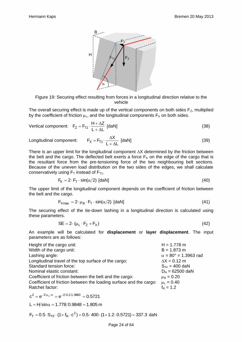
The securing effects change with the lashing angle. Figure 20 uses the same plausible
values for , H and B as Section 1.4.4 to show the securing effect curves compared with those derived from the simplified mathematical models in VDI 2702, DIN EN 12195-1:2004 and DIN EN 12195-1:2011. All five curves are subject to the same conditions as in the
example for = 80° that we calculated above.
Comparison with the mathematical models shows that, in a longitudinal direction also, the actual securing effect is considerably greater than indicated by the simplified mathematical models. In order to produce a value, the magnitude of which is comparable with the securing
effect in a lateral direction, the longitudinal movement of the cargo X was changed from 0.10 m to 0.12 m.
The difference between the securing effect to the rear and the securing effect to the front that appears in DIN EN 12195-1:2011 seems peculiar, because there is no physical basis for it. In fact, it is said that when they adopted this definition, the committee responsible was attempting to compensate for the different assumptions made across Europe with respect to the loads arising from forces acting in a longitudinal direction to the front.
Hermann Kaps Bremen 20 May 2013
Page 26 of 64
Figure 20: Securing effect of longitudinal forces, comparison of mathematical models
1.4.6 Securing moment in a lateral direction relative to the vehicle
It is only necessary to check that a tie-down lashing is suitable for securing cargo against tipping if the stability of the cargo unit is insufficient. Put simply, this applies to units whose contact width B is less than 60% of their height H. Taken together with the width of the loading area of approximately 2.5 m, and a maximum cargo height of approximately 3 m, this restricts the plausible lashing angles to a range between around 45° to a maximum of 83°. The following plausible cargo dimensions were chosen to demonstrate the securing effect
against tipping over this range. They are based on B = 0.48 H:
Lashing angle 45° 60° 70° 80°
Cargo height H 1.008 m 1.529 m 2.070 m 3.002 m
Cargo width B 0.484 m 0.734 m 0.993 m 1.441 m
The initial pre-tensioning force FT in accordance with Equation (15) is changed due to the movement of the cargo as a result of an external load. In addition to the types of movement investigated in Section 1.4.4, namely displacement/layer displacement and frame deformation, we shall here additionally investigate the possibility of tilting. Making the appropriate changes to the length of the belt on the left and right, Equations (30), (31) and (32) provide the necessary parameters for the calculation.
BL2
D)LL(FF N
rightleftT1T
[daN]
L2
D)LL(F
Nrightleft
[m]
2
2
1Tmaxc1
c1FF
[daN]

Hermann Kaps Bremen 20 May 2013
Page 27 of 64
FT1 + F
FT1 F
+
B – Y Y
H
tipping axis
Figure 21: Securing effect resulting from moments in a lateral direction relative to the vehicle
In order to account for movement of the cargo when formulating the securing moments, it is
necessary that the lever B of the left-hand vertical component is reduced by Y and also that
the right-hand vertical component with the lever Y has a tilting effect (Figure 21). These represent small reductions in the securing effect compared with the simplified mathematical models provided in the standards. However, the following calculations show that these reductions in the securing effect against tipping in a lateral direction remain minimal, because
only small values of Y are necessary in order to establish the desired lateral components of the pre-tensioning forces.
The complete securing effect against tipping is made up of SE1 = moment from the vertical components of the forces in the left and right sections of the belt and of SE2 = moment from the difference between the horizontal components of these forces.
Y)sin()FF()YB()sin()FF(SE 1T1T1 [daNm]
)cosFsinF(Y2)cos(sin)FF(BSE 1T1T1 [daNm] (43)
)]cos()FF()cos()FF[(HSE 1T1T2 [daNm]
)sinFcosF(H2SE 1T2 [daNm] (44)
21 SESESE [daNm]
SE = overall securing effect [daNm] B = contact width of the cargo unit [m] H = height of the cargo unit [m] FT1 = equalized, corrected pre-tensioning force [daN] according to Equation (30)
F = change to pre-tension force [daN] according to Equation (31), limited by Equation (32)
Y = lateral movement of the top surface of the cargo [m]
= initial lashing angle [°]
= change to lashing angle [rad] according to Equation (17)
In these derivations, simplifications have as before been made by making on the left and
on the right equal, and by using cos = 1 and sin = . The subtrahend in SE1
" Y)sin()FF( 1T " is not required if the cargo unit only slides, because the tipping
edge on the bottom of the cargo also shifts sideways. However, this is rather unlikely, as the cargo unit here is, by definition, liable to tip and is therefore more likely to tilt than to slide.
We shall calculate an example of tilting by 0.5° as a reactive movement. The input parameters are as follows:
Height of the cargo unit: H = 3.002 m Width of the cargo unit: B = 1.441 m
Lashing angle: = 80° = 1.3963 rad

Hermann Kaps Bremen 20 May 2013
Page 28 of 64
Lateral travel of the top surface of the cargo: Y = 0.0262 m Standard tension force: STF = 400 daN Nominal elastic constant: DN = 62500 daN
Coefficient of friction between the belt and the cargo: B = 0.20 Ratchet factor: fR = 1.2
5721.0eec 3963.12.0222 B
3.337)5721.02.11(4005.0)cf1(S5.0F 2RTFT daN
048.39848.0002.3sinHL m
0126.00262.0002.3
441.1Y
H
Bzleft m
0001.0002.30262.0002.3HYHz 2222right m
L)HB1(Y)cosLB(Y2LL 2222left [m]
01703.0048.3)48.01(0262.0)1736.0048.3441.1(0262.02048.3L 222left
00455.0048.31736.00262.0048.32048.3LcosYL2LL 22right
008465.0048.3
9848.00262.0
L
sinY
rad
BL2
D)LL(FF N
rightleftT1T
[daN]
8.440441.1048.32
62500)00455.001703.0(3.337F 1T
daN
3.221048.32
62500)00455.001703.0(
L2
D)LL(F
Nrightleft
daN
0.1205721.01
5721.018.440
c1
c1FF
2
2
1Tmax
daN
)cosFsinF(Y2)cos(sin)FF(BSE 1T1T1 [daNm]
5.788)0015.08.4409848.00.120(0262.02)0015.09848.0(8.560441.1SE1
)sinFcosF(H2SE 1T2 [daNm]
2.147)00834.08.4401736.00.120(002.32SE2 daNm
7.9352.1475.788SESESE 21 daNm
As a comparison, the securing effect is calculated in accordance with VDI 2702:
6.5679848.0400441.1sinSBSE TF daNm
This comparison shows that the actual securing effect after the cargo unit has tilted slightly is considerably greater than the securing effect calculated according to the recommendation, which is now regarded as outdated, in the VDI 2702 Guideline of 2000. Conversely, this means that if securing is carried out according to this guideline, the cargo would probably not tip at all, because the other movements of the cargo such as sliding, layer displacement or frame deformation would alone be sufficient to achieve the necessary securing effect. This probable behaviour will be verified below using the following conservative assumptions:
- The lateral travel Y is chosen in such a way that it is just large enough over the selected range of possible lashing angles between 45° and 80° to exactly achieve the change in

Hermann Kaps Bremen 20 May 2013
Page 29 of 64
length L required to achieve the maximum possible difference in force F resulting from Euler's friction.
- As a result of the first assumption, the vertical travel Z is so small that the belt as a whole is subject to virtually no change in length, i.e. FT1 = FT.
Figure 22: Securing effect of lateral moments, comparison of mathematical models
The curves in Figure 22 show that despite the conservative assumptions made, the actual securing effect exceeds that given by all the current mathematical models. The model given in DIN EN 12195-1:2004 is particularly striking. Lashing angles of less than 64° and the ratio B : H = 0.48 used here result in negative securing effects, i.e. in purely mathematical terms, the use of belts would increase the risk of tipping. This mathematical model is completely useless.
The lateral movement Y required to achieve the actual securing effect shown in Figure 22 is
just under 2 mm when = 45° and increases to just under 26 mm when = 80°. These values are significantly smaller than the movements required with a direct lashing in order to achieve the lashing capacity LC of the lashing equipment as normally determined in the balance calculation. This means that tilting is not required. Even a completely rigid cargo unit
that cannot itself be deformed in any way can achieve the necessary lateral movement Y by a small amount of sliding and/or deformation of the loading surface without tilting.
1.4.7 Securing moment in a longitudinal direction relative to the vehicle
A tie-down lashing placed laterally relative to the vehicle can act in the same way against tipping in a longitudinal direction as a direct lashing. Traditionally, direct lashings are assessed in such a way that their lashing capacity LC is used in a balance calculation. However, this approach presumes that the securing equipment stretches elastically to such an extent that the securing force increases from the initial pre-tensioning force FT up to the rated lashing capacity LC.
The amount of stretch required to achieve this can amount to several centimetres for a tie-down lashing and, in this case, where we are talking about securing cargo against tipping, is

Hermann Kaps Bremen 20 May 2013
Page 30 of 64
only achieved if the cargo tilts. Displacement and/or deformation are hardly sufficient for this scenario. Tilting of this magnitude, however, is associated with risks resulting from dynamic effects. In the example below, we estimate the potential magnitude of such tilting on the basis of a calculation.
Tilting with a securing force = LC
A homogeneous cargo unit with a weight W = 3200 daN, a width B = 1.873 m and a height H = 1.778 m is located transversely on the vehicle and secured with a lateral tie-down lashing. The tie-down lashing is placed halfway along the length of the cargo unit. The distance to the
front and rear tipping axis J = 0.444 m in both directions. The lashing angle = 80° on both sides. The lengths of the free belt sections L = 1.805 m on both sides.
FT1 FZ
FX
H
X
tipping axis
L
B
J
Figure 23: Securing effect resulting from moments in a longitudinal direction relative to the vehicle
The vertical components of the tie-down lashing that secure the cargo against tipping act on the lever J to the tipping axis. The moment balance calculation for tipping to the front on the basis of VDI 2702 is:
sinJF2JW2HWfl [daNm] (45)
7.9779848.0444.02
)444.0889.08.0(3200
sinJ2
)J2Hf(WF l
daN
If we interpret the minimum necessary force F required to maintain an equilibrium of moments in the two belt sections as the lashing capacity LC, a tie-down lashing with a single belt with a lashing capacity LC of 1000 daN would be sufficient. The nominal elastic constant DN for this belt is as follows for an assumed elastic stretch of 4% on reaching LC:
250004
1001000
p
100LCDN
daN
If we also assume that the belt has been pre-tensioned on both sides with a mean value of
330 daN, an increase in force of F1 = 648 daN is required on both sides. As a result of the
friction at the edges of the cargo, this increase is only approximately F2 = 490 daN in the horizontal central section of the belt. From this, the necessary change in length of the belt can be determined.
130.025000
873.1490805.16482
D
BF
D
LF2L
N
2
N
1
m
This change in length is distributed across both sides with a magnitude of 0.065 m on each side and results in the cargo moving upwards under the tie-down lashing by 6.6 cm, corresponding to a tilt of approximately 8.5°. Changes to the tilting geometry and the moment of rotational inertia of the tilting cargo during an emergency braking manoeuvre can cause

Hermann Kaps Bremen 20 May 2013
Page 31 of 64
this value to rise considerably, so that it seems inadvisable to interpret the necessary force as the lashing capacity LC.
It is presumably for this reason that the VDI 2702 Guideline of May 1990 and the VDI 2700, Part 2 Guideline of November 2002 include a mathematical model for this situation, in which a pre-tensioning force that should be limited to 50% of the lashing capacity LC is assumed as the securing force. The DIN EN 12195-1:2011 standard also proposes the pre-tensioning force STF (or a measured value) as the securing force and also introduces a safety factor into the calculation. This factor is 1.25 in the event of loads in the direction of travel and 1.1 in the event of loads against the direction of travel. The interim standard DIN EN 12195-1:2004 does not contain any suggestions for this scenario.
The mathematical models presented do not assume any reactive movement on the part of the cargo. Neither do they deal mathematically with any loss of friction if tensioners are used on one side only. Because this does not reflect reality, the actual securing effect of the tie-down lashing will be compared with the simplified mathematical models.
Securing effect with pre-tensioning force
We assume a movement of the cargo of the same magnitude as was used to present the securing forces in a longitudinal direction. The type of movement assumed is either frame deformation or tilting. Sliding is less probable because of the imminent risk of tipping and layer displacement is not considered for practical reasons.
In the event of frame deformation, the length of the belt does not change, and the pre-tensioning force does not, therefore, increase (Section 1.4.2). The force FT determined in Equation (15) is unchanged.
2
)cf1(SF
2RTF
T
[daN]
In addition to the longitudinal movement X, there is also a small vertical movement of the
top surface of the cargo Z according to Equation (24). In this case, the value of Z is negative.
HXHz 22 [m]
The overall securing effect is made up of the vertical components FZ on both sides, multiplied
by the lever (J – X) to the tipping axis, and the longitudinal components FX on both sides,
multiplied by the lever (H + Z).
Vertical component: L
ZHFF TZ
[daN]
Longitudinal component: L
XFF TX
[daN]
According to Equation (41), the upper limit of the longitudinal component is:
)2sin(F2F TBmaxX [daN]
We now calculate the securing effect of the tie-down lashing against tipping in a longitudinal direction.
XZ F)ZH(F)XJ(2SE [daNm] (46)
SE = overall securing effect [daNm] J = lever of the vertical components of the tie-down lashing to the tipping axis [m] FT = equalized pre-tensioning force according to Equation (15) [daN] FZ = vertical component of FT [daN] FX = horizontal component of FT [daN] H = height of the cargo unit [m]

Hermann Kaps Bremen 20 May 2013
Page 32 of 64
L = length of the free belt section [m]
X = longitudinal movement of the top surface of the cargo [m]
Z = vertical movement of the top surface of the cargo [m]
B = coefficient of friction between the belt and the cargo
= lashing angle [°]
We shall perform an example calculation. The input parameters are as follows:
Height of the cargo unit: H = 1.778 m Width of the cargo unit: B = 1.873 m Distance of the belt from the tipping axis: J = 0.444 m
Lashing angle: = 80° = 1.3963 rad
Longitudinal travel of the top surface of the cargo: X = 0.1 m Standard tension force: STF = 400 daN Nominal elastic constant: DN = 62500 daN
Coefficient of friction between the belt and the cargo: B = 0.20 Ratchet factor: fR = 1.2
5721.0eec 3963.12.0222 B
3.337)5721.02.11(4005.0)cf1(S5.0F 2RTFT daN
805.19848.0778.1sinHL m
0028.0778.11.0778.1HXHz 2222 m
7.331805.1
0028.0778.13.337
L
ZHFF TZ
daN
7.18805.1
1.03.337
L
XFF TX
daN
7.866428.03.3372.02)2sin(F2F TWmaxX daN
6.294)7.18775.17.331344.0(2F)ZH(F)XJ(2SE XZ daNm
As a comparison, the securing effect is calculated in accordance with DIN EN 12195-1:2011:
To the front: 8.27925.1
9848.0400444.02
25.1
sinSJ2SE TF
daNm
To the rear: 0.3181.1
9848.0400444.02
1.1
sinSJ2SE TF
daNm
This shows that under the assumption that the type of movement is frame deformation, the actual securing effect is smaller than that calculated by the mathematical model in DIN EN 12195-1:2011 for loads acting to the rear, but larger for loads acting to the front. We have already commented on this peculiarity at the end of Section 1.4.5.
If the actual securing effect of a tie-down lashing that has been dimensioned for loads to the rear in accordance with the mathematical model above (i.e. weaker) is not able to withstand the load, the cargo unit will inevitably tilt as soon as its increasing inner rigidity prevents any
further deformation. It is perfectly possible that this can happen even if X < 0.1 m.
We shall now calculate the same example using a tilting value of = 0.5° as a reactive movement.
0155.000873.0778.1tanHX m
0039.00155.0778.1
444.0X
H
JZ m

Hermann Kaps Bremen 20 May 2013
Page 33 of 64
L)HJ1(XXJ2LL 2222 [m]
0039.0805.1062.100024.00155.0444.02805.1L 2 m
2.4269.883.337873.1805.12
625000039.023.337
BL2
DL2FF N
T1T
daN
8.4190039.0805.1
0039.0778.12.426
LL
ZHFF 1TZ
daN
7.30039.0805.1
0155.02.426
LL
XFF 1TX
daN
6.1096428.02.4262.02)2sin(F2F TWmaxX daN
5.372)7.3782.18.419428.0(2F)ZH(F)XJ(2SE XZ daNm
This result exceeds both mathematical models given in DIN EN 12195-1:2011, which means that the cargo can be expected to tilt by less than 0.5° under the given conditions.
The calculated securing effects change with the lashing angle. The results shown in Figure 24 show that the mathematical models given in DIN EN 12195-1:2011 are sufficient. Nevertheless, when securing cargo against tipping to the rear, a small amount of tilting < 0.5° can be expected if the securing is dimensioned without any significant reserves.
Figure 24: Securing effect of longitudinal moments, comparison of mathematical models
1.4.8 Influence of the coefficient of friction between the lashing material and the cargo
The mathematical models used to represent the actual securing effect of a tie-down lashing depend to a considerable extent on the pre-tensioning force FT. This pre-tensioning force is based on the standard tension force STF of the belt used and on the transmission coefficient

Hermann Kaps Bremen 20 May 2013
Page 34 of 64
k, which was used in the form (1 + c2) in the calculations above. A large value for c2 assumes a low coefficient of friction between the belt and the cargo.
On the other hand, the securing effect of a tie-down lashing benefits from the difference between the transverse components of the pre-tensioning forces on the two sides when loaded in a lateral direction relative to the vehicle, in particular if the lashing angles are small. This difference increases with a large coefficient of friction between the belt and the cargo. This applies both to the securing forces and to the securing moments. In the event of a load in a longitudinal direction, the first of these influences is the dominant one, namely a low coefficient of friction between the belt and the cargo.
This somewhat confusing situation will be clarified in the diagrams below.
Figure 25: Securing effect of lateral forces, influence of the coefficient of friction between the belt and the cargo
Figure 25 provides an example showing that the coefficient of friction between the belt and the cargo should be kept to a minimum in order to maximize the securing effect in the form of transverse forces. This applies especially in the event of large lashing angles. In the event of small lashing angles of less than 70°, the significance of this influence is reduced and, indeed, is inverted slightly for lashing angles of less than 60°. However, because small lashing angles are only technically feasible for low, narrow cargo units, such angles indicate a securing scenario in which direct securing would possibly be the better option.
This means that as a basic principle the coefficient of friction between the belt and the cargo should be kept as low as possible with the large lashing angles that are usual in day-to-day practice. This is achieved using suitable edge protectors. In very specific circumstances with small lashing angles, it can, however, be better to place anti-slip material under the belts at the edges of the cargo.

Hermann Kaps Bremen 20 May 2013
Page 35 of 64
Figure 26: Securing effect of lateral moments, influence of the coefficient of friction between the belt and the cargo
Figure 26 shows the opposite effect of the coefficient of friction between the belt and the cargo if the tie-down lashing is to be used to secure the cargo against tipping. A large coefficient of friction favours the transverse components acting with the larger lever H to such an extent that it overrides the overall lower level of pre-tensioning force. The smaller the ratio B : H, i.e. the more liable a cargo unit is to tip, the greater this effect. In cases such as this, anti-slip material should be placed under the lashing belts. These comments should not distract from the fact that a direct lashing would possibly be the better option for securing against tipping in such cases.
Figures 27 and 28 show that the securing effects in the form of both forces and moments in a longitudinal direction relative to the vehicle certainly benefit from a low coefficient of friction between the belt and the cargo. This reinforces the basic recommendation that low-friction edge protectors should be used. Because longitudinal components of the lashing forces are also intended to be transmitted to the edge of the cargo when securing against longitudinal forces, it is advisable that the edge protectors should feature suitable beads or protrusions to prevent the belt from slipping in a longitudinal direction. This is regularly the case with narrow edge protectors, simply to prevent the belt from slipping off the side of the protector.

Hermann Kaps Bremen 20 May 2013
Page 36 of 64
Figure 27: Securing effect of longitudinal forces, influence of the coefficient of friction between the belt and the cargo
Figure 28: Securing effect of longitudinal moments, influence of the coefficient of friction between the belt and the cargo

Hermann Kaps Bremen 20 May 2013
Page 37 of 64
1.5 Practical implementation
The considerations and calculation methods presented in Section 1.4 representing the actual securing effect of a tie-down lashing and covering the four requirements "preventing cargo from sliding laterally and longitudinally" and "preventing cargo from tipping laterally and longitudinally" are scarcely suitable for practical use. They could be used with a calculation program for one-off calculation of standardized securing concepts. But even then, it would be advisable to carry out practical trials in order to calibrate any tolerances that may apply given specific cargo behaviour and other assumptions that were made, such as the elastic stretch and hysteresis behaviour of lashing belts.
For day-to-day use in correctly dimensioning any cargo securing measures and for use in police inspections, it is important to have simplified, recognized mathematical models. These should take the form of arithmetic rules or tables with the least possible number of parameters and which provide information on the number of tie-down lashings required. After all, this is ultimately the issue confronting any driver: "How many belts will I need to lash down the cargo before I can set off?"
1.5.1 Simplified assessment models
Section 1.4 demonstrated that current, and still controversial, mathematical models presented in the German VDI 2700, Part 2 Guideline and the two versions of DIN EN 12195-1 from 2004 and 2011 sometimes differ considerably, even when the same parameters are assumed, and that the results they deliver deviate from a more accurate determination of the securing effect, but largely err on the side of caution. We can assert the following:
- All of the mathematical models in DIN EN 12195-1:2011 are adequate. Nevertheless, the two different safety factors for longitudinal loads relative to the vehicle to the front and to the rear cannot be substantiated on the basis of the physical mechanisms involved.
- The mathematical models in VDI 2700, Part 2 differ from those in DIN EN 12195-1:2011 by the absence of the safety factor. The results they deliver therefore have a slightly lower margin of safety.
- The mathematical models in DIN EN 12195-1:2004 for lateral and longitudinal securing forces differ considerably from those in DIN EN 12195-1:2011, namely by 17.5%. In the case of lateral tipping loads, the discrepancies run into several hundred percent, for the reasons we have described. The reasons why these discrepancies arose have been discussed in Sections 1.3.2 and 1.3.3.
This means that it would be possible to agree on the mathematical models presented in DIN EN 12195-1:2011. However, this does not mean that these models cannot be improved.
The curves in Figures 18 and 20 show that the actual securing effect initially increases as the lashing angle decreases, whereas the commonly used mathematical models show a decreasing sinusoidal curve. It therefore seems reasonable to simply remove the factor
"sin" used in these mathematical models for lashing angles between 45° and 90°. This also applies to the curves in Figures 22 and 24, although in this case the issue is somewhat obscured by the fact that the width of the cargo B and the lever J also decrease as the lashing angle decreases. It is thus possible to formulate the following mathematical models for lashing angles between 45° and 90°:
Lateral and longitudinal sliding: TFL S8.1SE [daN] (Figure 29) (48)
Lateral tipping: TFSBSE [daNm] (Figure 30, left) (49)
Longitudinal tipping: TFSJ5.1SE [daNm] (Figure 30, right) (50)
In the case of lashing angles less than 45°, tie-down lashing becomes increasingly ineffective and other securing methods must be used instead.

Hermann Kaps Bremen 20 May 2013
Page 38 of 64
0
50
100
150
200
250
300
350
400
450
45 50 55 60 65 70 75 80 85 90
lashing angle alpha [°]
secu
rin
g e
ffect
[daN
]
0
50
100
150
200
250
300
350
400
450
45 50 55 60 65 70 75 80 85 90
lashing angle alpha [°]
secu
rin
g e
ffect
[daN
]
Figure 29: Alternative model for the securing effect (blue)
0
100
200
300
400
500
600
700
800
45 50 55 60 65 70 75 80
lashing angle alpha [°]
secu
rin
g e
ffect
[daN
*m]
0
50
100
150
200
250
300
350
400
450
45 50 55 60 65 70 75 80 85 90
lashing angle alpha [°]
secu
rin
g e
ffect
[daN
*m]
Figure 30: Alternative models for the securing effect (blue)
The blue curves in Figures 29 and 30 represent the securing effects in accordance with the proposed simplified models given in Equations (48) through (50). The green curves show the actual securing effects from Figures 18, 20, 22 and 24. At this point, it is important to note that the proposed simplification of the mathematical models is entirely independent of the open question as to which coefficient of friction is to be used in Equation (48). This issue must be dealt with separately.
This does not, however, resolve the shortcoming in the conventional mathematical models described in Section 1.2, namely that the horizontal components of the tie-down lashing that arise as a result of friction between the belt and the cargo are ignored, which means that the
existing dominance of the coefficient of friction L or the resting moment lever b is further exaggerated. This minor shortcoming could be resolved by employing a small, fixed proportion of the standard tension force STF. The securing effect against lateral and longitudinal sliding could then be as follows, for instance:
Lateral and longitudinal sliding: TFL S)1.05.1(SE [daN] (51)
However, it seems that the expense of more complex formulae is not worthwhile for the sake of a cosmetic change such as this.
1.5.2 Coefficient of friction between the loading surface and the cargo
The crucial question of what coefficient of friction between the cargo and the loading surface to use in a mathematical model for tie-down lashings cannot be answered on the basis of the considerations and calculations offered in Section 1.4. The choice is between a value that approximates to the coefficient of static friction, as proposed by the DIN EN 12195-1:2011 standard, and the coefficient of dynamic friction, as required by the predecessor standard DIN EN 12195-1:2004 and the VDI 2700, Part 2 Guideline. This decision affects both the
Alternative mathematical model for lateral securing force
Alternative mathematical model for longitudinal securing force
Alternative mathematical model for lateral securing moment
Alternative mathematical model for longitudinal securing moment

Hermann Kaps Bremen 20 May 2013
Page 39 of 64
actual securing effect and the securing effect determined on the basis of simplified mathematical models to much the same extent.
As a fundamental principle, careful long-term analysis of claims and accidents should form the basis for an economically viable decision in this respect. However, as long as not even the minimum requirements for an adequate tie-down lashing appear to have been met in the majority of registered cases, it is difficult to draw the correct conclusions from experience to date. This decision has a serious impact due to the non-linear nature of the effect of the coefficient of friction on the number of belts that need to be employed (cf. Figure 3). This has been described in Section 1.2. The arguments on both sides that have been voiced to date are as follows:
1. All practical trials indicate that the cargo starts to move when subjected to extreme loads, in other words that it can possibly slide until such time as the changes to the geometry of the tie-down lashing, and possibly further force being developed by the belts stretching, leads to the movement being stopped and the cargo being restrained. During this brief period, the coefficient of dynamic friction is acting.
2. The simplified mathematical models for tie-down lashings are designed in such a way that they require and produce an equilibrium of forces without assuming that the cargo moves. It is therefore appropriate to use the coefficient of static friction.
The reference to practical trials in the first argument reflects a holistic approach. It includes the actual circumstances surrounding an event in which a cargo is subjected to a load. These include all positive and negative influences, such as small vertical accelerations, small additional dynamic loads as a result of movement of the cargo and the entire securing effect of the tie-down lashing as described in Section 1.4.
The second argument refers to the simplified mathematical models and can even claim that the actual securing effect will generally even be somewhat larger than indicated by the models. On the other hand, part of this gain is "used up" by the fact that, at least in the model proposed in DIN EN 12195-1:2011, the coefficient of transmission k is not fully accounted for and must therefore be compensated for by additional effects, as indeed it is. It is, however, undoubtedly the case that the second argument fails to take account of the circumstances surrounding a real load scenario, i.e. vertical accelerations and dynamic effects.
The following considerations can also be raised independently of the arguments discussed:
- Many cargoes that are secured using tie-down lashings, such as pallets loaded with individual packages, exhibit behaviour under load in which the movement is primarily elastic and/or plastic deformation before the entire cargo unit slides. Such deformations are often sufficient to allow the complete securing effect of the tie-down lashing to be established without the cargo sliding. This supports the argument for using a coefficient that approximates to the coefficient of static friction.
- Extreme load scenarios are relatively rare on the roads and, if they happen, they will not necessarily be repeated. This reduces the risk of larger movements of the cargo and could be an argument for using a larger coefficient. On the other hand, this does not apply to cargoes on road vehicles transported overseas in intermodal operations, where unfavourable movements of the ship can be repeated many times if the vessel encounters rough seas. In this case, a coefficient that is closer to the coefficient of dynamic friction would be more appropriate.
In 2004, the discussions that followed the publication of the EN 12195-1:2003 standard led to a series of practical trials being carried out in Sweden. These were intended to clarify a number of contentious issues. One of these issues was the question of what coefficient of friction to use when dimensioning tie-down lashings.
This involved six practical trials with emergency braking. The longitudinal and vertical accelerations were recorded. The cargo, which was secured with tie-down lashings, was a roll of paper, weighing 600 kg and standing on end. The coefficient of static friction between

Hermann Kaps Bremen 20 May 2013
Page 40 of 64
the roll of paper and the loading surface had previously been determined to be 0.54 on the basis of three pulling tests. The tie-down lashing was made up of one polyester belt attached
crosswise across the vehicle with a lashing angle on both sides of = 58.7°. For each of the six trials, the pre-tensioning force for the tie-down lashing was gradually reduced.
Trial no.
Mean deceleration
Pre-tensioning force before the trial (both
sides)
Pre-tensioning force after the trial (both sides)
Notional coefficient of friction for equilibrium
of forces
1 6.76 m/s2 600 kg - 0.372 no sliding
2 6.95 m/s2 600 kg - 0.382 no sliding
3 6.97 m/s2 500 kg 500 kg 0.415 no sliding
4 6.96 m/s2 400 kg 400 kg 0.452 no sliding
5 7.14 m/s2 300 kg 310 kg 0.510 no sliding
6 7.27 m/s2 250 kg 390 kg 0.547 slides 45 mm
Using the coefficient of dynamic friction, the tie-down lashing that was the subject of the trial would have required a pre-tensioning force of approximately 600 daN (as the sum of both sides). Using the coefficient of static friction, however, it would have required only approximately 250 daN. As expected, the series of trials showed that the cargo only starts sliding when the necessary securing force is greater than the friction that can be provided by the coefficient of static friction. This was the case in the sixth trial where the coefficient of static friction of 0.54 was exceeded. In the fifth trial, the slight increase in the pre-tensioning force indicates that the roll of paper was just about to move.
After the static friction had been overcome in the sixth trial, the roll of paper began to move forward. At this point, the forward-acting inertial force becomes greater than the lower dynamic friction that now applies, triggering an acceleration of the roll of paper. This movement is, however, quickly inhibited because the belt is forced to stretch, thus increasing its tension. In addition, the displacement of the roll causes a small, rearward and directly acting force component. This is caused by the additional securing effects of the tie-down lashing described for longitudinal sliding in Section 1.4.5 of this paper.
Although it is hardly surprising, this series of trials and its results clearly demonstrate the dilemma inherent in this problem. If the tie-down lashing is dimensioned on the basis of the coefficient of dynamic friction, it can be assumed with a considerable degree of certainty that the cargo will never slide in the event of it being subjected to the defined reference load. However, securing the cargo in this case involves a considerable amount of effort due to the non-linear nature of the influence of friction, as has been mentioned several times, and this effort would in effect be wasted, because this amount of securing would never actually be called upon. In economic terms, this is a dubious approach.
If, on the other hand, the tie-down lashing is dimensioned on the basis of the coefficient of static friction, it is, for several reasons, possible that the lashing will not quite be adequate and the cargo will begin to move as a result of the lower coefficient of dynamic friction. Although the additional securing effect of the tie-down lashing described in Section 1.4 will generally be able to restrain the cargo, this is not certain. We should also not forget that some of this additional effect is intended to compensate for other deficits of the simplified mathematical models.
The conclusion drawn in the Verify-Report6 states that the vertical accelerations that occur under emergency braking do not have any significant impact and therefore the use of the coefficient of static friction when dimensioning a tie-down lashing is "correct in physical terms". This conclusion cannot be accepted without reservations. It is too biased in the context of the considerations listed above. Not only that, the small number of trials and the fact that the experiment was conducted only on a particular type of vehicle and a single type of cargo mean that the trials were not sufficient to draw such a general conclusion.
6 Available as a PDF file at www.mariterm.se

Hermann Kaps Bremen 20 May 2013
Page 41 of 64
A solomonic solution that should satisfy everybody could be as follows: The mathematical model should use a gradually reduced coefficient of static friction which would require that a somewhat larger number of belts or greater pre-tensioning forces would need to be used than with the actual coefficient of static friction. In this way it would be possible to reduce the probability that the actual coefficient of static friction is insufficient to an absolute minimum, which would be accepted by everyone.
It is conceivable that the definition of the coefficient of friction to be used for tie-down lashings as laid down in Annex B of the DIN EN 12195-1:2011 standard is very close to this
solution. This standard specifies the use of a standard value that can be empirically determined in two different ways:
1. Five tipping tests are used to determine the mean angle of inclination at which the cargo unit under investigation begins to slide. This happens when the maximum possible level of static friction is reached. The standard coefficient of friction is then defined as follows:
tan925.0 (52)
2. Pulling tests which are described in greater detail7 and in which sliding is registered are carried out, resulting in a mean ratio between the tractive force and the weight force. The tractive force is equal to the dynamic friction. The standard coefficient of friction is then defined as follows:
forcew eight925.0
forcetractive95.0
(53)
The standardized equality of these two results and their relationships to static friction and dynamic friction permit a conclusion regarding the assumed relationship between dynamic
friction D and static friction S. Of course, any such relationship can only be understood as an approximate reference value, because, as is known, no physical regularity applies here.
856.0925.0 2
S
D
Anticipating Chapter 2, we should mention here that, when taking account of friction with a
direct lashing according to DIN EN 12195-1:2011, the standard coefficient of friction as
defined above should be reduced by a factor of f = 0.75. A coefficient of friction of
0.75 0.925 S = 0.694 S is thus proposed for evaluating a direct lashing.
A study completed in Germany in 20078 entitled "Investigation of the effectiveness of frictional forces when securing loaded goods for transportation" came to entirely different conclusions and recommendations. The study contains the results of pulling tests using anti-slip materials and pulling tests with and without tie-down lashings under quasi-stationary conditions and under the influence of vertical vibrations of the loading surface. The tests with and without tie-down lashings are important in the current context.
7 The brief description corresponds to the detailed instructions contained in the German VDI 2700 Part 14
Guideline of September 2011 dealing with the determination of coefficients of friction. 8 Carried out by the Department of Logistics (Flog) at the University of Dortmund for the German Vehicle
Operator's Trade Association BGF.

Hermann Kaps Bremen 20 May 2013
Page 42 of 64
Figure 31: Coefficients of friction during pulling tests without tie-down lashings (source: Flog)
Figure 31 shows the coefficients of friction derived from the ratio between tractive force and weight force from a series of three trials using the material pair of structured screen-printed laminate deck and rough-sawn Euro pallet.
In the first trial, the coefficient of static friction is 0.3, and then falls to 0.26 and 0.24. The mean coefficient of dynamic friction is 0.18. These values are remarkably low compared with other specifications for the same pair of materials that have been under discussion.
DIN EN 12195-1:2004: S = 0.5 D = 0.35
DIN EN 12195-1:2011: S = 0.4865 D = 0.4164 (converted from standard )
In a reference test, the same cargo unit weighing 400 daN was secured with two tie-down
lashings with lashing angles of = 80° on both sides and a pre-tensioning force of around 350 daN on both sides. This cargo unit was then pulled. Note: This tie-down lashing was dimensioned in such a way that it should have been able to withstand a tractive force corresponding to a deceleration of 0.8 g without sliding, assuming a coefficient of friction of 0.18. This is shown in the following balance calculation:
80sin35018.0440018.04008.0 [daN]
32024872320 daN
The coefficient of friction of 0.18 that was assumed approximately corresponds to the mean coefficient of dynamic friction from the previous trial. Using the coefficient of static friction of approximately 0.30 determined in that trial, the cargo unit should only have started to slide at a tractive force of 484 daN. This would correspond to a deceleration of 1.21 g. In fact, however, in the first trial the cargo unit began to slip at a tractive force of less than 200 daN, i.e. at half its own weight, as shown by the chart in Figure 32.

Hermann Kaps Bremen 20 May 2013
Page 43 of 64
Figure 32: Coefficients of friction during pulling tests with tie-down lashings (source: Flog)
The fact that the coefficients of friction appear to increase in the second and third trials is the result of elastic stretch and the increase of force of the belts and of their longitudinal component, which acts directly. These increase the tractive force applied during the trials and hence the apparent coefficient of friction.
The University of Dortmund study puts the surprisingly large shortfall in securing effect down to possible settling effects and plastic stretch of the lashing belts along with other influences. This does not, however, appear particularly plausible. If we assume the same coefficient of
static friction S = 0.3 as in the first trial without tie-down lashings, the effective mean pre-tensioning force FT in the tie-down lashings when the cargo begins to slide can be calculated to give a tractive force of 0.48 times the weight. The balance calculation reads:
80sinF3.044003.040048.0 T [daN]
61985.03.04
40018.0FT
daN
It is not particularly likely that the pre-tensioning force fell so dramatically from around 350 daN to around 60 daN as a result of settling effects or plastic stretch of the belts.
Despite this open question, or perhaps precisely because the issue could not be resolved, the authors of the study concluded that "the coefficient of dynamic friction should be used rather than the coefficient of static friction when calculating cargo securing measures. The experiments conducted have shown that this requirement should be regarded as an absolute minimum which must be observed."
This recommendation was made in 2007, but clearly carried no weight during the consultation phase leading up to the new version of EN 12195-1 between 2008 and 2010, with the consequence that the mean value between the static and dynamic coefficients of friction was to be taken as the standard.
On the other hand, this study had a lasting impact on the VDI 2700 Part 14 Guideline published in September 2011 under the title "Determination of coefficients of friction". This guideline defines a safety factor S = 0.95 by which the coefficient of dynamic friction established with pulling tests is to be multiplied before it can be used to assess cargo-securing measures. To the surprise of some European delegations, this safety factor then appears in EN 12195-1:2010 and DIN EN 12195-1:2011 (see Equation (53) above).

Hermann Kaps Bremen 20 May 2013
Page 44 of 64
2. Direct securing
When securing cargoes to a vehicle, the term "direct securing" refers to all methods whose primary mode of action makes use of "positive locking" force transmission between the cargo and the vehicle. This is the key difference compared with friction securing (tie-down lashing), whose primary mode of action is a "non-positive" or "frictional" connection between the cargo and the vehicle, which is merely increased somewhat by the tie-down lashing.
Whereas the effect of force transmission through positive-locked connections is limited by the strength of the material used for securing, friction is subject to greater restrictions, which are only marginally influenced by the material used for securing. This means that direct securing can be more efficient than friction securing using similar materials by something in the region of the power of ten.
Example: A belt used for a direct lashing can be loaded up to its lashing capacity LC of, e.g. 2500 daN. If the same belt is used as a tie-down lashing and is tensioned with the standard
tension force STF of 400 daN, and if a coefficient of friction = 0.3 is taken, it provides a
maximum securing effect of 2 0.3 400 = 240 daN.
If a belt is used to secure a cargo directly and is attached at an angle that differs from the required securing direction, its effectiveness is reduced. The mathematical models in the guidelines and standards discussed account for this in a reasonably uniform manner.
However, none of the specifications take mathematical account of the fact that the potential securing effect is only achieved after the cargo moves noticeably. If the lashing angles are unfavourable, such movement can be of a dangerous magnitude. Only in the DIN EN 12195-1:2011 standard is the necessary movement of the cargo mentioned, with the consequent requirement that the coefficient of dynamic friction should be reduced by 25% before it is used in the force balance calculations for the longitudinal and lateral directions. This can be understood to be the coefficient of dynamic friction.
The fact that the effectiveness of direct securing depends on movement of the cargo also has a further consequence, namely that combinations of securing equipment that act directly can only act with their full lashing capacity LC if they have the same elastic properties relative to the direction in which the cargo moves. These restrictions surrounding the use of direct lashings will be explained in more detail with examples in the sections below.
2.1 Necessary movement of the cargo
According to Hooke's law, all solid bodies, which includes cargo-securing equipment, must deform when they transmit a force. For lashing equipment, this deformation will take the form of stretching, and for blocking equipment, it will take the form of compression. If such deformation remains within the permitted range, it will be elastic. In other words, the deformation is not permanent, and the force transmission process can be repeated any number of times. And this is precisely what we expect of cargo-securing equipment.
Hooke's law further states that for practical applications in the lower load range, the load absorbed and the associated deformation are proportional to each other. This simplifies all calculations. This assumption fits very well for metallic lashing materials and rather less so for synthetic fibre belts, although it is still adequate here (see Figure 17). This assumption can also be made for timber used for blocking if it is subjected to loads over brief periods.
The concept of the elastic constant as introduced in Section 1.4.3 is used to determine the movement of the cargo necessary to transmit forces on the basis of Hooke's law. The elastic
constant D permits simple conversion of a change in length L to a change in force F and vice versa as shown in Equation (26):
LΔDFΔ [daN]

Hermann Kaps Bremen 20 May 2013
Page 45 of 64
As we have already explained in Section 1.4.3, it makes sense to initially use the nominal elastic constant DN, which is independent of the length of the securing equipment and only depends on its cross-section and a material constant. The following applies in accordance with Equation (27):
p
100LCDN
[daN] (p = percentage elongation)
and in accordance with Equation (28):
L
DD N [daN/m]
Assuming 4% elastic stretch for lashing belts and 1.5% elastic stretch for chains, this allows us to derive the following values for the nominal elastic constants in daN when the LC is reached:
LC 500 daN 1000 daN 2500 daN 5000 daN 10000 daN
Ready-made lashing belts 12500 25000 62500 125000 250000
Short-link lashing chains 33333 66666 166666 333333 666666
2.1.1 Lashing devices
Lashing devices for direct securing are attached between a securing point on the cargo unit and a securing point on the vehicle. Depending on the precise circumstances, the direction of the lashing device will deviate from the ideal, which should be aligned with the direction of the force to be transmitted. The resulting lashing geometry has a considerable impact on the movement of the cargo that is required to transmit the forces.
Figure 33 shows a lashing of the length L running at a vertical angle to the loading surface. The horizontal angle of the lashing also deviates from the longitudinal axis of the vehicle by
an angle of x. The concomitant deviation from the lateral axis of the vehicle is represented
by the horizontal angle y.
Equally well as by the description above based on angles, the lashing geometry can be described by the geometrical components of the lashing X, Y and Z. This option makes the formulae somewhat clearer and will be preferred below.
X
L Z
Y
y
x
Figure 33: Geometry of a direct lashing
The three-dimensional version of Pythagoras' theorem applies to the above-mentioned components X, Y and Z and the length L of the lashing (where L is the internal diagonal of a cuboid with the sides X, Y, Z):
2222 ZYXL [m] (54)
The lashing is defined as having a pre-tensioning force of FT. In order to reach the lashing
capacity LC, it must stretch by the distance L. The following applies:

Hermann Kaps Bremen 20 May 2013
Page 46 of 64
N
T
D
L)FLC(LΔ
[m] (55)
Sliding movement of the cargo
If a load is applied in the direction x, the cargo unit must move by the distance X in order to
cause the change in length L. Applying Pythagoras' theorem:
XZY)LΔL(XΔ 222 [m] (56)
If a load is applied in the direction y, the cargo unit must move by the distance Y.
YZX)LΔL(YΔ 222 [m] (57)
Equation (55) shows that the change in length L can be kept to a low value for a given lashing capacity LC by applying a high pre-tensioning force FT, by keeping the length of the lashing L as short as possible, and/or by using a material with a large nominal elastic constant, such as a steel chain instead of a synthetic fibre belt.
Equations (56) and (57) can be reformulated in such a way that it is possible to estimate the relationship between the movement of the cargo and the change in length. These reformulations are as follows:
XΔX2
LΔL2
LΔ
XΔ
and
YΔY2
LΔL2
LΔ
YΔ
(58)
If we consider that the two added values are small compared with twice the base values, the following provides sufficient accuracy:
X
L
LΔ
XΔ and
Y
L
LΔ
YΔ (59)
The movements of the cargo are therefore virtually always greater than the changes in length, and never smaller. They can only be restricted by the magnitude of the changes in length if the lashing is only arranged in the x direction or y direction, i.e. if it has no other components. However, if X or Y is close to or equal to zero, which should anyway be regarded as an extremely inefficient arrangement, the approximations (59) provide incorrect
results, which are too large. Calculation of X and Y using Equations (56) and (57) should therefore always be preferred.
Example: We shall calculate a simple example in order to demonstrate the sort of magnitude we are dealing with. A lashing is attached in a manner similar to that shown in Figure 33, with the following length components: X = 1.4 m, Y = 2.0 m, Z = 1.3 m. The length of the lashing is thus:
766.23.10.24.1ZYXL 222222 m
The lashing is a single lashing belt with an LC of 2500 daN. It has been pre-tensioned to STF = 400 daN. The change in length necessary to reach the LC is:
093.062500
766.2)4002500(
D
L)FLC(L
N
T
m
If a load is applied in the x direction, the necessary movement of the cargo as per Equation (56) is:
176.04.13.10.2859.2XZY)LL(X 222222 m
If a load is applied in the y direction, the necessary movement of the cargo as per Equation (57) is:

Hermann Kaps Bremen 20 May 2013
Page 47 of 64
127.00.23.14.1859.2XZX)LL(Y 222222 m
Neither of these results is extreme, but nevertheless demonstrate that a considerable movement of the cargo can be necessary if it is secured directly using belts.
Tipping movement of the cargo
A cargo unit that is liable to tip rather than slide must tilt by a small angle in order to generate the elastic stretch necessary for the lashing to reach its load capacity. In this case also, it is possible to identify a simple relationship between the change in length and the tilt angle.
Z
Y
X
h
b
L
tipping axis
y
z
new position of securing point
Figure 34: Direct lashing to prevent tipping
Because the tilt angle is small, it is possible to determine the new position of the lashing point on the cargo unit using a simplified approach.
hY [m] and bZ [m]
The three-dimensional version of Pythagoras' theorem provides the desired relationship
between L and for tilting laterally relative to the vehicle.
2222 )bZ()hY(X)LL( [m2]
After additional reformulation and acceptable simplifications, we get:
ZbYh
LL
[rad] (60)
Example: We shall calculate a simple example in order to demonstrate the sort of magnitude we are dealing with. A lashing is attached in a manner similar to that shown in Figure 34, with the following length components: X = 0.9 m, Y = 0.7 m, Z = 2.0 m. The length of the lashing is thus:
302.20.27.09.0ZYXL 222222 m
The lashing is a single lashing belt with an LC of 2500 daN. It has been pre-tensioned to STF = 400 daN. The change in length necessary to reach the LC is:
077.062500
302.2)4002500(
D
L)FLC(L
N
T
m
The distances to the tipping axis are h = 1.9 m and b = 1.2 m. This gives the tilt angle in accordance with Equation (60).
Hermann Kaps Bremen 20 May 2013
Page 48 of 64
0475.00.22.17.09.1
302.2077.0
ZbYh
LL
rad; = 2.7°
Tilting through 2.7°, for instance, causes the cargo unit to rise by some 6 cm on the side opposite the tipping axis.
2.1.2 Blocking devices
Blocking devices are subject to compressive forces. Because blocking materials are liable to be ejected to the side if forces are applied in an oblique direction, they are usually arranged in such a way that they act in precisely the direction in which the load is expected. This simplifies any consideration of the necessary movement of the cargo. This movement is of exactly the same magnitude as the change in length of the blocking material, or, more accurately, as the amount by which the blocking material must be compressed in order to transmit the compressive force in accordance with Hooke's law.
The elements involved in blocking on road vehicles comprise the boundary element of the loading platform, i.e. an elastic end wall, side wall, stanchion or special superstructure, and the filling elements, which will generally be wooden blocks, pallets or even air bags. This makes it difficult to determine an elastic constant that is anything like reliable and would make it possible to estimate the deformation from the blocking force. Furthermore, many blocking materials are rarely in full contact at the beginning of a journey, which means that if a load is applied, there is initially a small amount of unhindered movement before the opposing blocking force is established. This unhindered movement should be kept to a minimum in order to prevent the moving cargo from building up too much kinetic energy.
Despite these uncertainties, we can assume that deliberate blocking, for instance using wooden beams between the cargo and the end wall would, in the event of being subjected to the load for which it was designed, only require or allow the cargo to move by a few centimetres before the entire load is taken up, which is considerably less than is the case for the majority of lashings.
2.2 Permitted pre-tensioning force for a direct lashing
Direct lashings should always be positioned on two sides, so that the securing effect is established to the front and back or to the left and right. If a pre-tensioning force is applied everywhere, the securing effect of the lashings (which are generally inclined) in the initial condition is made up solely of the increase in friction between the cargo and the loading surface which is generated by the vertical components of the pre-tensioning forces. The horizontal components of the pre-tensioning forces largely cancel each other out. This means that there is initially no difference between direct lashing and tie-down lashing.
The full lashing capacity LC of the lashing equipment only takes effect when the cargo has moved or become deformed as a result of an external force (generally inertial force during a braking manoeuvre or cornering) to such an extent that, on the loaded side, the force in the lashing increases by elongation from the pre-tensioning force to the lashing capacity LC and, on the opposite side, decreases to zero by contraction. The mathematical models for dimensioning a direct lashing generally found in the standards and guidelines only apply under these circumstances. These models always assume that the lashing force on the opposite side is equal to zero.
In practice, these requirements are generally achieved without difficulty. The initial pre-tensioning force on both sides is important in this respect. If, for example, this is 50% of the value of LC, and if the lashing equipment is arranged symmetrically on both sides and has the same degree of elasticity, this ideal state is exactly achieved. If the pre-tensioning force is greater, a (detrimental) residual force would remain on the opposite side or the LC value would be exceeded on the loaded side. This means that a pre-tensioning force of 50% of LC is the limit case for mechanically symmetrical arrangements. The VDI 2702 Guideline, for instance, makes explicit reference to this.

Hermann Kaps Bremen 20 May 2013
Page 49 of 64
This limit decreases in the event of asymmetrical arrangements. It is not possible to offer a simple rule of thumb in this context. We shall explain this with an example.
Example: A cargo unit has been secured to the front and back using belts with a lashing capacity LC of 1000 daN arranged crosswise and tensioned to a pre-tensioning force FT = 500 daN. The geometry of the belts is as follows:
Front : X = 0.5 m, Y = 2.4 m, Z = 1.8 m; 041.38.14.25.0L 222 m
Rear : X = 2.0 m, Y = 2.4 m, Z = 1.8 m; 3.6062
1.82
2.42
2.0L m
X
X
L
X
L
fore rear
Figure 35: Asymmetrical direct lashing
The two rear belts must stretch by a distance L when the full lashing capacity LC is required during emergency braking.
072.025000
606.3500
D
L)FLC(L
N
T
m
This elongation is achieved by the cargo unit moving by the distance X.
128.00.28.14.2678.3XZY)LL(X 222222 m
This movement causes the front belts to be shortened by L.
018.0041.38.14.2372.0LZY)XX(L 222222 m
This shortening reduces the pre-tensioning force in the front belts by F.
148041.3
25000018.0
L
DLF N daN
Because the front belts were pre-tensioned to a force of 500 daN, they still retain a tensioning force of 360 daN when the rear belts have already reached their lashing capacity LC. This reduces their securing effect in the horizontal component. This reduction is, however, mitigated or cancelled out because the vertical components of the front belts make a positive contribution to the securing effect in terms of the friction value between the cargo and the loading surface. The overall securing effect of this asymmetrical arrangement is calculated in the following section.
A pre-tensioning force of 50% of the lashing capacity is only rarely achieved with lashing materials, and settling effects mean that the pre-tensioning force falls slightly after a short time. This means that the problem of excessive pre-tensioning forces rarely occurs with belts. In the case of lashing chains with high-quality tensioning equipment, excessive pre-tensioning is possible using certain unauthorized tools, and must be absolutely avoided. The advice found in manufacturers' brochures that chain lashings should only be "hand tight" should not, however, be understood to mean that the chains should be attached "loose". The optimum pre-tensioning force threshold of 40% to 50% of the lashing capacity LC also applies to chains.

Hermann Kaps Bremen 20 May 2013
Page 50 of 64
2.3 Securing effect of a direct lashing arrangement
2.3.1 Effect against horizontal movement (displacement, deformation)
As with tie-down lashings, the securing effect of a direct lashing arrangement against horizontal forces is made up of the partial effects of the horizontal component and the vertical component of the lashing force, which always acts downwards on road vehicles and thus achieves a securing effect by means of increasing the friction. Whereas the increase in
friction is the dominant aspect with tie-down lashings, the lashing angle in a direct lashing should be kept as small as possible to ensure that the more effective horizontal component is thoroughly exploited (Figure 36 left).
All guidelines and standards agree that the coefficient of dynamic friction should be taken as the coefficient of friction, because there is a high degree of probability that the cargo will need to slide in order to achieve the maximum securing effect, as explained in the preceding sections. The securing effect of a direct lashing against displacement of the cargo unit is described by the following equations:
LL
Z
LL
XXLCSE DX [daN] (61)
LL
Z
LL
YYLCSE DY [daN] (62)
You should note that correct calculation requires that the horizontal components which have
been increased by the small sliding distances X and Y and the length L that has been
increased by L should be used in both equations. This is not done in any of the common mathematical models. Instead, the initial values X, Y and L are used, because the movement of the cargo is completely ignored. However, this means that the results are always on the safe side. Nevertheless, given small initial values for X or Y (which represent unfavourable securing geometry anyway), the discrepancies between the common mathematical models and the results of Equations (61) and (62) are considerable. In this respect, the simplified mathematical models are appropriate and adequate for force balance calculations.
At this point, we shall calculate the securing effect for the example given in the previous
section with a coefficient of dynamic friction D = 0.3.
9.14891.398.1450023.3
8.13.0372.03522
678.3
8.13.0128.210002SEX
daN
The conventional approach to calculation gives the following result for the same situation:
8.1408606.3
8.13.00.210002
L
Z
L
XLCnSE DX
daN
This means that the result for this example deviates by around 5% on the safe side from the result of a more precise calculation. This assessment does not take into account the dynamics of moving cargo, which somewhat increase the securing requirements.

Hermann Kaps Bremen 20 May 2013
Page 51 of 64
Y
Z
(Y+Y)
(L+L)
LC
h Z
(Y+Y)
b
LC
(h+
Z)
(Z+
Z)
(b-Y)
Figure 36: Securing effects against sliding and tipping
2.3.2 Effect against tipping
The securing effect of a direct lashing against tipping is also made up of the partial effects of the horizontal component and the vertical component of the lashing force. A precise calculation should take into account any possible tilting and the resulting changes to the effective forces and levers. Using the values on the right of Figure 36, the equation for the securing effect in a lateral direction relative to the vehicle is as follows:
)Zh(
LL
YY)Yb(
LL
ZZLCSEY [daNm] (63)
The commonly used, simplified model is also shown for comparison purposes.
h
L
Yb
L
ZLCSEY [daNm]
The differences between the results are generally negligible. Nevertheless, the results of the simplified models deviate towards the side that provides less safety. They are always somewhat larger than the exact results. The simplified mathematical models for tipping balance calculations are nevertheless appropriate and adequate.
The securing effect of a direct lashing against tipping in a longitudinal direction relative to the vehicle is similarly calculated in accordance with Equation (63).
On the right of Figure 36, you should note that the value for b in the chosen example is negative (b = horizontal distance of the lashing point on the cargo unit from the tipping axis). The vertical component of the lashing force supports the outer tilting moment. Direct lashings that are attached crosswise are therefore less effective for securing the cargo against tipping than lashings inclined at a steep angle.
2.4 Static indeterminacy with complex direct securing scenarios
Complex cargo-securing scenarios can be made up of a combination of securing equipment with different degrees of elasticity, different dimensions, and acting in different directions. Under these conditions, the static load on the individual items of securing equipment is uncertain and depends entirely on the way in which each item of equipment is itself deformed by the movement or deformation of the cargo unit. It is an invalid approach to use the lashing capacity LC for each of these items of securing equipment in force or moment balance calculations. This important aspect has already been raised in the report " Securing cargo in road transport – Who knows the truth?".
In that report, a 'selective calculation approach' was described which allows the problem of static indeterminacy to be approximated and resolved with a sufficient degree of accuracy. The selective approach starts with the item of cargo-securing equipment in the arrangement

Hermann Kaps Bremen 20 May 2013
Page 52 of 64
under consideration which will be first to reach its lashing capacity in a given load scenario. On the basis of the change in length of the selected cargo-securing means, this loading is converted into a cargo movement/deformation. The latter are used to determine the changes in length of and loads absorbed by all further cargo-securing means and these values are input into a balance calculation. This calculation method is illustrated in the following section for the force balance calculation in the X direction.
2.4.1 Different lashing angles and lengths
If several items of lashing equipment are used to secure a cargo directly with different lashing angles, different lengths and cross-sections and different pre-tensioning forces, one must first identify the most "sensitive" item, i.e. the one which reaches its lashing capacity LC with the smallest amount of movement of the cargo. Because this task does not demand
extreme accuracy, the simplified equations (59) are used to convert L to X. Equation (55)
is first used to determine the necessary change in length L for each item of lashing equipment.
N
T
D
L)FLC(LΔ
[m]
The reformulated Equation (59) gives the associated X for each of the items under
consideration and the resulting smallest value for Xmin.
XD
L)FLC(XΔ
N
2T
min
[m]
The following equation then gives the expected loads FW for the remaining items from Xmin:
Tmin2N
W FXΔL
XDF
[daN] (64)
We shall demonstrate this calculation sequence on the basis of a simple example. A cargo unit is secured against sliding in the direction of travel with six direct lashings (Figure 37). Three different types of lashing are used in this scenario, each of which comprises different components. The lashing belts chosen have a lashing capacity LC of 1000 daN and a nominal elastic constant DN of 25000 daN. The calculation is performed using a spread sheeting program.
type 1 type 2
type 3
Figure 37: Complex direct lashing
The table in Figure 38 shows the results, assuming that the same pre-tensioning force of 400 daN was applied to all the belts. The Type 1 lashings reach their lashing capacity of 1000
daN after the cargo has moved in a longitudinal direction by a distance of X = 0.055 m. This distance is only sufficient to increase the load on the Type 2 lashings to 614 daN and on the Type 3 lashings to 697 daN. This means that the total securing effect is reduced correspondingly.

Hermann Kaps Bremen 20 May 2013
Page 53 of 64
Figure 38: Distribution of the applied load with the same pre-tensioning forces
If a lower pre-tensioning force is applied to those lashings that reach their lashing capacity first, and a greater pre-tensioning force is applied to the rest, it is possible to increase the "yield" in terms of securing effect. This has been done in Figure 39, although the unavoidable consequence of this is that under these conditions the cargo unit must slide by a distance of
X = 0.077 m in order to bring the Type 1 lashings up to their lashing capacity of 1000 daN. Given the somewhat greater pre-tensioning force, the other lashings nevertheless achieve around 80% and 92% of their capacity.
Figure 39: Distribution of the applied load with adjusted pre-tensioning forces
If the commonly used guidelines and standards had been followed, all three types of lashing would have been assigned a load of LC = 1000 daN.
2.4.2 Different securing materials
Simultaneous use of different securing materials, e.g. belts and chains, also leads to a loss of securing effect due to the different elastic constants. The more elastic securing materials will always be loaded below their lashing capacity when the more rigid securing materials have already reached their load limit.
This effect is particularly dramatic if "rigid" blocking material is used in conjunction with elastic lashing belts. The classic example of this is when a heavy cargo is secured against sliding forwards by making use of the end wall of the loading platform.
The DIN EN 12642:2007 standard specifies the following load capacity for end walls: 0.4 x the payload weight up to a maximum of 5000 daN for standard superstructures (Code L) and 0.5 x the payload weight for reinforced superstructures (Code XL). The standard also specifies the maximum permitted elastic deformation during type testing. However, this specification is extremely general in nature and does not allow us to make realistic assumptions about the deformation of an end wall that can be expected if its load capacity is exploited.
If only the lower part of the end wall is subjected to a load, it is "less sensitive" and will only deform by a few centimetres when its capacity is fully exploited. If the entire height of the end wall is subjected to a load, which assumes a certain amount of deformation of the cargo, the permitted deformation is likely to be in the region of decimetres. This deformation can be
interpreted as the distance Xmin, making it possible to estimate the loads to which belts that have been used in parallel will be subjected. Equation (64) can be used for any belt or chain in this situation.
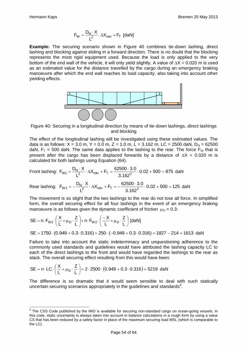
Hermann Kaps Bremen 20 May 2013
Page 54 of 64
Tmin2N
W FXL
XDF
[daN]
Example: The securing scenario shown in Figure 40 combines tie-down lashing, direct lashing and blocking against sliding in a forward direction. There is no doubt that the blocking represents the most rigid equipment used. Because the load is only applied to the very
bottom of the end wall of the vehicle, it will only yield slightly. A value of X = 0.020 m is used as an estimated value for the distance travelled by the cargo during an emergency braking manoeuvre after which the end wall reaches its load capacity, also taking into account other yielding effects.
Figure 40: Securing in a longitudinal direction by means of tie-down lashings, direct lashings and blocking
The effect of the longitudinal lashing will be investigated using these estimated values. The data is as follows: X = 3.0 m, Y = 0.0 m, Z = 1.0 m, L = 3.162 m, LC = 2500 daN, DN = 62500 daN, FT = 500 daN. The same data applies to the lashing to the rear. The force FW that is
present after the cargo has been displaced forwards by a distance of X = 0.020 m is calculated for both lashings using Equation (64).
Front lashing: 87550002.0162.3
0.362500FX
L
XDF
2Tmin2N
1W
daN
Rear lashing: 12550002.0162.3
0.362500FX
L
XDF
2Tmin2N
2W
daN
The movement is so slight that the two lashings to the rear do not lose all force. In simplified form, the overall securing effect for all four lashings in the event of an emergency braking
manoeuvre is as follows given the dynamic coefficient of friction D = 0.3:
L
Z
L
XFn
L
Z
L
XFnSE D2WD1W [daN]
16132141827)316.03.0949.0(250)316.03.0949.0(1750SE daN
Failure to take into account the static indeterminacy and unquestioning adherence to the commonly used standards and guidelines would have attributed the lashing capacity LC to each of the direct lashings to the front and would have regarded the lashings to the rear as slack. The overall securing effect resulting from this would have been:
5219316.03.0949.025002L
Z
L
XLCnSE D
daN
The difference is so dramatic that it would seem sensible to deal with such statically uncertain securing scenarios appropriately in the guidelines and standards9.
9 The CSS Code published by the IMO is available for securing non-standard cargo on ocean-going vessels. In
this code, static uncertainty is always taken into account in balance calculations in a rough form by using a value CS that has been reduced by a safety factor in place of the maximum securing load MSL (which is comparable to the LC).

Hermann Kaps Bremen 20 May 2013
Page 55 of 64
3. Miscellaneous
3.1 Rolling factor
3.1.1 Physical causes
The "rolling factor" is one of the contentious issues surrounding the securing of cargo on road vehicles in Europe. This value used in calculation first makes a one-off appearance in the German VDI 2702 Guideline and then subsequently in the EN 12185-1:2003 standard as a supplement to the lateral acceleration factor 0.5. In both cases, this supplement has a magnitude of 0.2 and is only to be used for assessing securing against tipping in a lateral direction relative to the direction of travel if the cargo unit concerned is not innately stable given a lateral acceleration of 0.7 g.
The reason given for this supplementary factor is to "take account of dynamic tilting moments brought about by a non-steady-state lateral inclination or by angular acceleration from rolling
oscillations of the vehicle about its longitudinal axis when the vehicle is cornering".
The report "Securing cargo in road transport – Who knows the truth?" demonstrated that when steady-state cornering is initiated rapidly, when changing lanes and in the event of rapid avoiding action, the increase in lateral acceleration is overlaid by angular accelerations from oscillations of the loading surface about the longitudinal axis of the vehicle.
Depending on the suspension of the vehicle, such oscillations can occur with a periodicity of around 1.5 s and amplitudes of around 3°. The angular accelerations from these oscillations are of the magnitude 1 s-2 and bring about tangential forces. Together with centrifugal force and the parallel component of the force of gravity due to the inclined loading surface, these are included in the calculation as the common inertial force in the centre of gravity of the cargo unit. This means that the tangential forces from the angular accelerations are integral components of the lateral force resulting from the specified lateral acceleration of 0.5 g. The quasi-static tilting moment of the cargo unit is made up of this lateral force and the vertical lever between the centre of gravity of the cargo and the tipping axis.
In this common and perfectly usable conceptual model, it is, as a simplification, assumed that the mass of the cargo unit is concentrated at its centre of gravity. In fact, however, any mass has a spatial dimension and reacts to angular accelerations with rotational inertia. This rotational inertia in turn leads to an additional tilting moment, which is not included in the mathematical model used, because a punctiform mass cannot possess rotational inertia. The somewhat complex calculation of this additional tilting moment is replaced by a fixed increase in the assumed lateral acceleration in the guidelines and standards referred to. This is the background to the justification for the rolling factor cited above.
The report "Securing cargo in road transport – Who knows the truth?" used plausible assumptions to calculate that this rolling factor should have a maximum of 0.1 g, due to the mechanisms described. In fact, even this value can only be achieved with a cargo unit whose height and width are at the limit of what is permitted on the roads, i.e. a cargo unit that possesses a considerable amount of rotational inertia.
It is unclear why those who introduced the rolling factor opted for the rather large value of 0.2 g. Records or minutes of the consultations do not exist or are not available. One supposition is that the suspension of commercial vehicles in the past was rather different and the damping properties of such systems were not as good as in modern-day commercial vehicles, with the result that far larger rolling oscillations were used in the calculations. It is also possible that a larger rolling factor than would have been required by the additional tilting moment due to rotational inertia was intended to limit the tilting of cargo units as described in several places above and the associated dynamic effects.

Hermann Kaps Bremen 20 May 2013
Page 56 of 64
3.1.2 Problems with acceptance
Whereas this rolling factor was defined with a value of 0.2 g in DIN EN 12195-1:2004, it was reduced to 0.1 g in DIN EN 12195-1:2011 on the basis of additional, independent expert opinions. However, the standard made the use of the rolling factor subject to conditions which effectively "abolished" it. For the coefficient of lateral acceleration cy, these conditions are as follows:
Securing against tipping using tie-down lashings: cy = 0.5 with FT = STF
or: cy = 0.6 with FT = 0.5 LC
Securing against tipping using direct lashings: cy = 0.6 with FR = LC
The majority of cargo-securing scenarios on the roads are tie-down lashings, of which only a small proportion are intended to secure the cargo against tipping. In virtually all such cases, the pre-tensioning force that can be achieved is likely to be equal to STF, with the result that a value of 0.5 for cy can be used for calculation, i.e. the rolling factor need not be used.
We should not forget to mention that in the same standard the criterion for establishing tipping stability has been formulated incorrectly. There, proof of tipping stability is given as:
dc
cb
z
yy [m] (65)
by
d
Fy = cymg
Fz = czmg
Figure 41: Tipping stability as a result of inherent stability
The following should be used: cy = 0.5 and cz = 1. In this case, according to the standard, a
cargo unit where, for example, by = 0.55d would still not be at risk of tipping. According to the standard, it would be possible to secure this cargo unit using only blocking methods at its base to prevent it from sliding.
In fact, however, the rotational inertia of a body is always present. It does not only appear if the cargo is liable to tip, as the note on the use of the rolling factor could possibly suggest. Consequently, it is necessary to check the inherent stability with a fixed tilting moment of
0.6mgd. However, with a stability lever of b = 0.55d, the inherent stability moment is only
0.55mgd. This would therefore not be able to prevent tipping alone. The checking criterion should therefore be changed accordingly.
Similar oscillations of the loading surface about the lateral axis also arise as a result of a rapid braking manoeuvre or aggressive pulling away. Such oscillations are known as pitching oscillations. Their amplitudes are smaller than those of rolling oscillations. On the other hand, their periodicity is shorter, so that the possibility of angular accelerations of the same magnitude as with rolling oscillations cannot be excluded. However, there are no known studies of this and none of the current German guidelines or standards make use of a "pitching factor".
Because the rolling factor was unknown in the rest of Europe and elsewhere in the world, its inclusion in the EN 12195-1 standard in 2003 was criticized by a good number of the delegations, in particular the Swedish delegation. As part of the practical trials in Sweden in 2004 already mentioned in Section 1.5.2, investigations were therefore carried out to identify whether the rolling factor was justified.

Hermann Kaps Bremen 20 May 2013
Page 57 of 64
However, the trials with a fully-laden truck were not fit for purpose as cargo units with relatively small dimensions were used as test objects (stacks each containing two rolls of paper with a total height of 2.27 m and a diameter of 1.0 m). The test also did not explicitly look at the effect of rotational inertia coupled with angular accelerations. The cornering manoeuvres were initiated extremely carefully and the maximum lateral acceleration was only reached after approximately 15 seconds, so that overlaid rolling oscillations were not able to develop. Instead, tie-down lashings with different pre-tensioning forces were tested, which delivered results that were able to confirm the additional securing effects of tie-down lashings and to disprove a number of assumptions made in the EN 12195-1:2003 standard, which had just been published.
The findings of the corresponding trials that are marginally relevant with respect to the rolling factor were that the vehicle's additional support wheel made contact with the ground at measured lateral accelerations significantly below 0.5 g. This led to the conclusion that the universally accepted assumption of a lateral acceleration of 0.5 g provided a considerable safety margin with respect to cargo securing, as this value would extremely rarely be achieved in practice. It is more likely that the vehicle would overturn.
In 2011, the CEFIC position paper already mentioned in section 1.3.4 on the EN 12195-1:2010 standard surprisingly included a statement on the rolling factor and its actual origin as a compensatory factor for the moment of rotational inertia. In the same breath, however, it rejects the idea of angular accelerations of sufficient magnitude during normal operation of a commercial vehicle that occur concurrently with other lateral accelerations that would justify the use of a rolling factor. However, CEFIC fails to provide any reference to plausibility considerations, calculations or measurements.
This uncertainty regarding how to handle the undeniable presence of rotational inertia of cargo units continues to this day. The draft of a new version of the German VDI 2700, Part 2 Guideline includes the rolling factor as a stability coefficient with a value of 0.1 g, as does the DIN EN 12195-1:2011 standard, but not only in the context of securing against tipping to the side, but also against tipping to the rear, although not to the front. The limitations included in DIN EN 12195-1:2011 are not present. This means that this factor is therefore intended to be used with both direct lashings and tie-down lashings.
In the international consultations regarding a new version of the Guidelines for Packing of Cargo Transport Units in the form of a new code10, the rolling factor was rejected, partly on the evidence of the results of the Swedish trials and the actual or supposed safety margin resulting from the assumption of 0.5 g lateral acceleration. The "German rolling factor", whatever deep significance it might have, would be covered by this safety margin.
This supposed or actual safety margin gives rise to economic considerations. If the lateral acceleration that can be achieved under normal operating conditions on the roads really were smaller by the margin claimed here, the majority of all cargoes that are not liable to tip and are lashed down correctly with tie-down lashings would be "over-secured" by some 50% to 100%. This is the consequence of the considerable non-linearity of the ratio between the coefficient of friction and the number of tie-down lashings required as described in Section 1.2. We shall demonstrate this with a brief example.
Example: A cargo with an overall weight of 8700 daN is secured against sliding laterally with
tie-down lashings using belts. Coefficient of friction = 0.3. Pre-tensioning force FT = 400
daN, lashing angle = 90°. According to DIN EN 12195-1:2011, the number of belts required is:
8975.71.140013.02
8700)3.05.0(f
Fsin2
gm)cc(n s
T
zy
10
Code of Practice for Packing of Cargo Transport Units (CTUs)

Hermann Kaps Bremen 20 May 2013
Page 58 of 64
If we had assumed a lateral acceleration of 0.4 g, i.e. without the safety margin that is being claimed, half the number of belts would be required in the same situation. This means that the "unnecessary" effort expended on securing the cargo would have been 100%.
4988.31.140013.02
8700)3.04.0(f
Fsin2
gm)cc(n s
T
zy
This consideration should encourage us to identify more reliable acceleration assumptions and make these available in the long-term. Values such as these should also be made dependent on the vehicle type, its suspension and other relevant characteristics.
Until such time as this is done, the value of 0.5 g will remain unchanged, even for securing scenarios involving only sliding. The additional risks for non-stable units resulting from their rotational inertia should be mitigated by additional securing measures in the interest of all parties involved, without being required to do so by a standard or a code. This is even more important the higher and wider a cargo unit is, i.e. the greater its rotational inertia.
3.2 Tipping test
Annex D of the DIN EN 12195-1:2011 standard contains a description of the "Practical tests for determination of the efficiency of cargo securing arrangements". These tests can be performed as an alternative to the suggested calculations and are particularly useful for cargo securing arrangements of a complexity that precludes simple, deterministic calculation. Typical applications include securing cargoes on pallets using shrink film and the use of plastic nets for securing. There are two methods to choose from: Dynamic driving tests in accordance with EN 12642:2006 or an inclination test11 described in greater detail in Annex D of DIN EN 12195-1:2011.
In the national preface to DIN EN 12195-1:2011, the complaint is made that the static tipping test (= inclination test) does not include dynamic effects. This criticism is intended to point out that securing arrangements that would pass the static tipping test may fail in a dynamic driving test. The static tipping test is also subject to the criticism that it uses the "mean"
coefficient of friction for tie-down lashings and blocking instead of the explicit coefficient of
dynamic friction D as was used in the 2004 predecessor to the standard.
3.2.1 Equivalence to mathematical models
Both these types of practical tests should be in a position to replace mathematical testing using the simplified mathematical model, and should therefore be equivalent not only to this model, but also to each other. Even at first glance, and without the need for extensive, long-term testing, it is clear that such equivalence can hardly be expected. We shall below make some remarks that are not intended to provide answers to open questions, but rather to attempt to state such questions more precisely. Once again, tie-down lashings are the focus of our attention.
The simplified mathematical model laid down in DIN EN 12195-1:2011 assumes a stationary horizontal acceleration and leaves the gravitational effect unchanged at 1 g for transportation on the road. The securing effect of the tie-down lashing is restricted to the increase in friction resulting from the vertical components of the pre-tensioning forces STF on both sides, with
these being reduced by a safety factor. The mean value is used as the coefficient of friction.
In terms of the stationary vertical and horizontal accelerations, the static tipping test is identical with the simplified mathematical model. However, this assumes that the mean coefficient of friction used to determine the test inclination is the same as the actual
11
The term "inclination test" appears in DIN EN 12195-1:2011 in both Annex B to describe a test for determining the coefficient of friction and in Annex D to describe a test for determining the effectiveness of cargo-securing measures. This ambiguity is misleading.

Hermann Kaps Bremen 20 May 2013
Page 59 of 64
coefficient of static friction. By definition, however, this is not so, because the mean coefficient of friction used is only 0.925 times the coefficient of static friction. This discrepancy means that the test inclination is set to a larger value than would be necessary with the actual coefficient of static friction. This means that the static tipping test gains a small safety margin. However, in the majority of cases this safety margin is exhausted and even exceeded because the greater amount of friction that actually applies makes the test appear to be successful with a smaller securing effect than the mathematical model requires with the smaller amount of friction. According to DIN EN 12195-1:2011, the tipping test is judged to be successful if the cargo unit under investigation "remains in position and only moves to a limited degree" at the test inclination.
Let us take an example to illuminate this rather opaque situation. The securing effect SE of a tie-down lashing or similar securing arrangement required by the mathematical model results from the difference between the inertial force and the friction from the weight at the mean
coefficient of friction used for calculation. Let us assume that the actual coefficient of static
friction in this example is S = 0.4. The resulting mean coefficient of friction is = 0.925 0.4 = 0.37. Let the weight of the cargo be 1000 daN. We are looking for the securing effect against sliding to the front under breaking deceleration of 0.8 g.
Mathematically necessary securing effect: SE = (0.8 – 0.37) 1000 = 430 daN
At = 0.37 we get an angle = 44.1° for the tipping test. The test is successful and the cargo does not slide. However, because the actual coefficient of friction of 0.4 is acting,
rather than the mean coefficient of friction = 0.37, a smaller securing effect than that calculated is sufficient.
Securing effect that is sufficient in the test: SE = (0.8 – 0.40) 1000 = 400 daN
This means that the tipping test requires less securing effect than the mathematical model. This weakness of the tipping test is mitigated somewhat by the fact that it represents the securing effect a little closer to reality, i.e. it takes account of small, permitted movements and deformations of the cargo, which can include a temporary drop in the coefficient of friction towards the value of the coefficient of dynamic friction. On the other hand, the dynamic effects that occur during a real emergency braking manoeuvre are not accounted for. These primarily take the form of fluctuations in the apparent weight due to vertical accelerations.
Dynamic driving tests rarely accurately reflect the mathematical model. The horizontal acceleration can be greater or smaller than the test value and includes overlaid fluctuations. Fluctuations in the vertical force lead to fluctuations in the friction. But here also the actual coefficient of static friction applies, which is higher than the mean coefficient of friction required by the mathematical model. On the other hand, a trend has been observed towards more pronounced movement of the cargo and hence a lower coefficient of dynamic friction. The securing effect of the tie-down lashing is rendered absolutely realistically.
From a realistic perspective, we should, of course, expect that the mathematical model reflects the dynamic driving tests and not vice versa. But questions related to the representation of complex events using simplified mathematical models do not merely involve technical and physical issues. Instead, they have to be answered in the light of an economically justifiable level of risk acceptance.
3.2.2 Practicability
If we assess the criticized tipping test irrespective of its equivalents to the mathematical model laid down in the standard, we find that it is thoroughly practicable. Using suitable experimental equipment (e.g. a tipper truck), the inclination test as described in B.1.2 of DIN EN 12195-1:2011 is first carried out with the unsecured cargo and the coefficient of friction is
determined with = 0.925 tan. On the basis of this coefficient of friction and the
coefficients of acceleration cx,y and cz that apply to transportation, the angle of inclination

Hermann Kaps Bremen 20 May 2013
Page 60 of 64
for the actual inclination test is calculated. The cargo is then secured and subjected to this
inclination using the same test equipment to determine whether the cargo remains in position.
If the cargo does not slide, the securing effect is clearly sufficient. If it does slide, the test must be repeated after improving the securing. If suitable precautionary measures are taken, this inclination test can be repeated multiple times without the risk of damage to the cargo. Any improvements that need to be made with regard to securing can also be easily identified with no risk by observing the behaviour of the cargo during the test. This can hardly be done with a driving test.
3.2.3 Enhancement for any vertical accelerations
Annex D of the DIN EN 12195-1:2011 standard has a further minor shortcoming. The scope of application of the standard includes transportation by sea and by rail. In these cases, the coefficient of acceleration cz can be less than 1. Table D.1 and Figure D.3, however, only
provide the test angles for the vertical coefficient of acceleration cz = 1, i.e. only for
transportation by road. The equation below provides the value for sin as a function of cx,y, cz
and for all modes of transportation covered. The parameter stands for the coefficient of friction to be used or for the ratio between the resting moment lever and the tipping moment lever if the test is intended to demonstrate the stability of the cargo in respect of tipping.
2
2zy,x
2zy,x
1
)cc(1ccsin
(66)
A substitution is made in order to solve Equation (66) with a greater degree of calculational reliability. This is as follows:
zy,x ccr
The value of r must be calculated and then used in the following, simpler equation:
2
22
1
r1rsin
(67)
The solution of Equation (67) can be verified against a table. The table shows the angle for
the input parameters r and .
r
1.0 0.9 0.8 0.7 0.6 0.5 0.4 0.3 0.2 0.1 0.0
0.00 90.0 64.2 53.1 44.4 36.9 30.0 23.6 17.5 11.5 5.7 0.0
0.05 90.0 66.9 55.9 47.2 39.7 32.8 26.4 20.3 14.4 8.6 2.9
0.10 90.0 69.3 58.5 49.9 42.4 35.5 29.2 23.1 17.2 11.4 5.7
0.15 90.0 71.4 60.8 52.3 44.9 38.2 31.8 25.8 19.9 14.2 8.5
0.20 90.0 73.3 63.0 54.7 47.3 40.7 34.4 28.4 22.6 16.9 11.3
0.25 90.0 74.9 64.9 56.8 49.6 43.1 36.9 31.0 25.2 19.6 14.0
0.30 90.0 76.2 66.7 58.8 51.8 45.3 39.2 33.4 27.7 22.2 16.7
0.35 90.0 77.4 68.3 60.6 53.8 47.4 41.5 35.7 30.2 24.7 19.3
0.40 90.0 78.5 69.8 62.3 55.7 49.5 43.6 38.0 32.5 27.1 21.8
0.45 90.0 79.4 71.1 63.9 57.4 51.4 45.6 40.1 34.7 29.5 24.2
0.50 90.0 80.2 72.3 65.3 59.0 53.1 47.5 42.1 36.9 31.7 26.6
0.55 90.0 80.9 73.3 66.6 60.5 54.8 49.3 44.1 38.9 33.8 28.8
0.60 90.0 81.5 74.3 67.9 61.9 56.4 51.0 45.9 40.8 35.9 31.0
0.65 90.0 82.0 75.1 69.0 63.2 57.8 52.6 47.6 42.7 37.8 33.0
0.70 90.0 82.5 75.9 70.0 64.4 59.2 54.1 49.2 44.4 39.7 35.0
0.75 90.0 82.9 76.7 70.9 65.6 60.4 55.5 50.8 46.1 41.5 36.9
0.80 90.0 83.3 77.3 71.8 66.6 61.6 56.9 52.2 47.6 43.1 38.7

Hermann Kaps Bremen 20 May 2013
Page 61 of 64
4. Summary
This paper primarily deals with the assessment of tie-down lashings and direct securing measures used to secure cargo on road vehicles. In day-to-day practice, extremely simplified mathematical models are used for such an assessment. Such models allow the carrier to determine the amount of securing required and also permit the police to perform inspections and, where necessary, provide an assessment that will stand up in court. Any simplified mathematical model for assessing a cargo-securing arrangement should not only be easy to use, but should above all realistically reflect the actual overall securing effect despite ignoring the small number of less significant side effects.
The current discrepancies between the mathematical models for tie-down lashings in the VDI 2700, Part 2 Guideline and the DIN EN 12195-1:2004 standard compared with the DIN EN 12195-1:2011 standard have only arisen over the past decade. The discrepancies result from differences in the simplifications used in the mathematical models. In particular, the DIN EN 12195-1:2004 standard, which has in fact now been superseded, includes the "k factor" in the calculation to account for the transmission loss of pre-tensioning force when tensioners are used on one side only, which leads to a 33% increase in the amount of securing required in order to comply with the standard.
The mathematical models for tie-down lashings have been presented in detail in this paper and compared with the actual securing effect, which is more complex. Some important aspects of the assessment of direct securing measures were also investigated. The results are summarized below:
1. The common mathematical models for determining the number of tie-down lashings required ignore side effects of a tie-down lashing that have the nature of direct securing measures and therefore provide inflated results, especially for small coefficients of friction or small resting moment levers in the case of units that are liable to tip. This means that the securing outlay appears to increase disproportionately for small coefficients of friction or small resting moment levers, which does not quite correspond to reality.
2. The use of the k factor of 1.5 to mathematically account for the transmission loss of pre-tensioning force in a tie-down lashing with one-sided tensioning, when the DIN EN 12195-1:2004 standard was introduced in Germany, was by and large accepted, even though there was no recognized evidence for the inadequacy of the previously applicable mathematical model in the VDI 2700, Part 2 Guideline, which did not include the k factor.
3. The way in which the new k factor was dealt with in DIN EN 12195-1:2004 was, on the one hand, inconsistent, because the lateral components that had been made available by the k factor were not taken into account in the sliding balance, although this was done in the tipping balance. In the latter case, they were evaluated in a way that made no physical sense, which led to completely unrealistic results. The reason for this incorrect evaluation was that movement of the cargo was ignored for cargo secured by tie-down lashings, although movements of this sort had always been presumed when assessing directly secured cargo.
4. The introduction of the standard tension force STF, to be determined by prototype testing according to the DIN EN 12195-2:2001 standard, led to speculation that engagement of the pawl of the ratchet tensioner with the previous tooth of the winding shaft would cancel out the transmission loss in the overall pre-tensioning force with reference to STF. This paper, however, demonstrates that this cancelling effect does not occur, but that generally the k factor only rises slightly.
5. In the case of direct securing, small movements or deformations of the cargo cause the initial pre-tensioning force on the side to which the load is applied to rise, allowing the lashing capacity LC of the relevant lashing equipment to be used in calculations. In the case of a tie-down lashing, on the other hand, the pre-tensioning force on the side to which the load is applied only increases to the extent permitted by the Euler ratio to the

Hermann Kaps Bremen 20 May 2013
Page 62 of 64
simultaneously falling force of the belt on the other side. In any event, however, the resulting configuration of horizontal components is beneficial with respect to securing.
6. For the entire range of lashing angles, the actual securing effect of a tie-down lashing against forces in transverse direction and forces in longitudinal direction relative to the vehicle is greater than the securing effect according to the mathematical models in the currently applicable DIN EN 12195-1:2011 standard and are by and large greater than the securing effect according to the mathematical model in the VDI 2700, Part 2 Guideline. Furthermore, the dependency of the securing effect on the sine of the lashing angle that underpins all the mathematical models to date is unfounded. The actual maximum for the securing effects is achieved with lashing angles of between 60° and 70°, and not at 90°.
7. For the entire range of lashing angles, the actual securing effect of a tie-down lashing against moments in transverse direction relative to the vehicle is greater than the securing effect according to the mathematical models in the currently applicable DIN EN 12195-1:2011 standard and in the VDI 2700, Part 2 Guideline. In this case also, the influence of the sine of the lashing angle that has been claimed is unnecessary.
8. For the entire range of lashing angles, the actual securing effect of a tie-down lashing against moments in a longitudinal direction relative to the vehicle is greater than the securing effect according to the mathematical models in the currently applicable DIN EN 12195-1:2011 standard and in the VDI 2700, Part 2 Guideline if a small degree of tilting of the cargo unit is permitted. Because a tie-down lashing essentially secures a cargo unit directly against tipping in a longitudinal direction if the lashing is arranged laterally, there is a temptation to use the lashing capacity LC as the securing force. It is urgently recommended that this should not be done, because this force is only achieved after the cargo tilts significantly. It should be mentioned that in this case also, the influence of the sine of the lashing angle that has been claimed is unnecessary.
9. In the case of a tie-down lashing, the coefficient of friction between the belt and the cargo should be as small as possible, i.e. 0.2 or smaller. This can be achieved using smooth, rounded edge protectors or similar low-friction materials. The exception to this rule is when securing cargo units that are liable to tip against tipping in a lateral direction, in which case it is more beneficial to have a large coefficient of friction between the belt and the cargo.
10. In Germany, discussions have ensued regarding a purported reduction in safety as a result of the introduction of the DIN EN 12195-1:2011 standard. In this respect, we can say that the new version DIN EN 12195-1:2011 places more stringent demands on a tie-down lashing than the VDI 2700, Part 2 Guideline, which is still used in parallel. Because this guideline is still recognized as the "generally accepted technical rules", the arguments against the DIN EN 12195-1:2011 standard are not consistent.
11. The mathematical models in the predecessor standard DIN EN 12195-1:2004 for transverse and longitudinal securing forces are 17.5% more stringent than those in DIN EN 12195-1:2011. In the case of tipping loads in a lateral direction, the discrepancies can run to several hundred percent. Aside from these discrepancies caused by a modelling error, the reduction in safety pointed to by critics is only around half the magnitude of the gain in safety resulting from the k factor introduced a few years earlier. DIN EN 12195-1:2011 thus represents an improvement in safety compared with the VDI 2700, Part 2 Guideline.
12. Although the instruments contained in DIN EN 12195-1:2011 appear to be acceptable on the basis of the findings indicated in points 10 and 11, this is not to say that this standard is not in need of correction and could not be improved. It is not, however, the main purpose of this paper to make suggestions for improvement.
13. As has already been noted in point 1 above, the coefficient of friction between the loading surface and the cargo that is chosen plays a key role in the simplified

Hermann Kaps Bremen 20 May 2013
Page 63 of 64
mathematical models for assessing a tie-down lashing used to secure a cargo against sliding. After weighing up the various opinions that are currently in circulation, we can support the proposal made in DIN EN 12195-1:2011 to use a mean value between the coefficient of static friction and the coefficient of dynamic friction.
14. Direct lashing forces are used in the common mathematical models at the value of the lashing capacity LC of the lashing equipment. The movement of the cargo in the direction of the external force that is required in order to achieve this force in the lashing equipment can and should be reduced to a minimum. This can be achieved by aligning the lashing equipment as closely as possible to the direction of the external force, by applying a high pre-tensioning force to the lashing equipment (although this must not exceed 40% to 50% of the LC) and by choosing lashing equipment with a large elastic constant.
15. The common mathematical models for assessing a direct securing arrangement do not take account of the necessary movement of the cargo, which is always present. This means that the results from the mathematical models differ from those of a more accurate calculation. For sliding balances, the discrepancies are on the "safe side" and for tipping balances, on the "unsafe side". As a whole, however, they can be tolerated.
16. If two or more items of cargo-securing equipment which secure the cargo directly in the same direction and which have different angles, different lengths and/or different elastic constants, are assessed using the common, simplified mathematical models, all the equipment is incorporated in a force or moment balance calculation at its LC. This approach is incorrect. When the item of securing equipment with the most favourable direction of action, the shortest length and/or the largest elastic constant reaches its lashing capacity LC, the other items have still, to a greater or lesser extent, not reached their LC. The securing arrangement is therefore inadequate or it is accepted that the first of these items of securing equipment (the "most rigid") will become overloaded. Suitable provision should be made in the guidelines and standards to take account of this.
17. The rolling factor introduced in the German VDI 2702 Guideline, that was intended to take account of additional tilting moments resulting from rotational accelerations of the loading surface and rotational inertia of the cargo, may have been the victim of misunderstandings during the course of the consultations on the DIN EN 12195-1:2011 standard. The reduction from 0.2 g to 0.1 g appears to be justified. However, the application criterion for identifying the risk of tipping is not correctly formulated and there is no physical evidence for the claimed dependency of the use of the rolling factor on the pre-tensioning force.
18. The static tipping test for establishing the appropriateness of securing arrangements that cannot be verified using the simplified mathematical models is not completely equivalent to the simplified mathematical models. The use in the test of a coefficient of static friction that has been "arbitrarily" reduced using a factor of 0.925 as specified causes the coefficient of static friction that actually applies to make it appear that a smaller securing effect would be sufficient than would be required by the mathematical model using the reduced coefficient of friction.
19. The standardized driving test that is permitted as an alternative necessarily includes dynamic effects. These effects generally cause greater movements of the cargo with the result that the discrepancy compared with the simplified mathematical model tends to occur on the other side. Thus it is both accurate and explicable that a static tipping test and a dynamic driving test are less equivalent to each other than either of the options are to the simplified mathematical model. The static tipping test, however, is easier to perform and can be done in a more controlled manner, and also corresponds sufficiently to the mathematical model.
20. One important insight for tie-down lashings is that any number of mathematical models or accurate coverage of all securing effects are useless and of no predictive value if day-to-day practice fails to ensure that the forces from the belts are transmitted to the entire

Hermann Kaps Bremen 20 May 2013
Page 64 of 64
cargo efficiently and across the greatest possible time span. This was clearly illustrated in the example of the hay wagon and the pole along the top which was presented at the beginning of this paper. In the case of normal cargoes on modern road vehicles, edge protectors and pressure distributors should be used for the same purpose. Accessories such as these are integral components of a tie-down lashing concept and should therefore be given a recognized role in assessing a tie-down lashing in the guidelines and standards.


![PDF version [2 MB]](https://img.dokumen.tips/doc/110x75/58a1aa751a28ab5c588bf80c/pdf-version-2-mb.jpg)