Embed Size (px)
Citation preview

PDA200E Induction Loop SystemInstallation Guide
Key FeaturesThe PDA200E is a cost-effective induction loop amplifier that is designed to drive a perimeterloop of up to 200 square metres. It provides the following key features:
• Fully compliant as a perimeter loop system as described in BS 7594, clause 10 A3 and BS EN 60118-4 when correctly installed
• Up to 200 square metres (metal free) coverage - ideal for most ‘free space’ applications• Two balanced / unbalanced line level inputs• One microphone input with phantom power for electret microphones (12 V)• Full compatibility with the Outreach plate audio input extension system• Metal compensation control to improve intelligibility in rooms with high metal content• Fully automatic compressor-limiter which maintains the loop signal for improved intelligibility• Each input has a separate internal tamper-resistant control that can be manually adjusted• Compression, output (Peak Current 3, 2, 1) and power on (Power) front panel indicators• Short circuit protection• Internal temperature safety cut-out to stop over heating• Wall-mounted metal enclosure for a permanent robust installation• Complete with installation kit, instructions and ‘loop fitted’ sticker• Contractor kits available - suitable for use in meeting rooms, TV lounges, places of worship, etc.
Approved Document No. DCP0002129 Rev 7 1 of 12
PLEASE READ THESE INSTRUCTIONS CAREFULLY BEFOREINSTALLING AND / OR MAINTAINING THIS EQUIPMENT.
Hint!Additional information about loop design can be found in the PDA Guide toAudio-Frequency Induction Loop Systems (AFILS), Document Number DLM0503700.
Approved Document No. DCP0002129 Rev 712 of 12
PDA200E 200m2 Induction Loop Amplifier & KitsPDA200E 200m2 wall-mounting induction loop amplifierAKM1 PDA200E 200m2 Meeting/seminar room loop kit
c/w PDA200E amplifier, APM omni-directional mic plate/cableAKL1 PDA200E 200m2 Lecture room loop kit
c/w PDA200E amplifier, AMT tie/desk mic, AML lectern mic, 2 x APJ plate/cableAKT1 PDA200E 200m2 TV / music lounge loop kit
c/w PDA200E amplifier, AMH handheld mic, APS scart lead, APJ plate/cable, APL plate/cableAKR1 PDA200E 200m2 Waiting room loop kit c/w PDA200E amplifier, APL plate/cableAKU1 PDA200E 200m2 Retail unit loop kit
c/w PDA200E amplifier, AML lectern mic, APJ plate/cableAKW1 PDA200E 200m2 Place of worship loop kit 1
c/w PDA200E amplifier, AML lectern mic, APJ plate/cable, APL plate/cableAKW2/L PDA200E 200m2 Place of worship loop kit 2 (lavalier mic. version)
c/w PDA200E amplifier, AMR/LA lavalier radio mic, APQM plate/cable, 2 x APXM plate/cableAKW2/H PDA200E 200m2 Place of worship loop kit 2 (handheld mic. version)
c/w PDA200E amplifier, AMR/HA handheld radio mic, APQM plate/cable, 2 x APXM plate/cableAKH1/L PDA200E 200m2 Health and fitness club loop kit (lavalier mic. version)
c/w PDA200E amplifier, AMR/LA lavalier radio mic, APQM plate/cable, APL plate/cableAKH1/H PDA200E 200m2 Health and fitness club loop kit (handheld mic. version)
c/w PDA200E amplifier, AMR/HA handheld radio mic, APQM plate/cable, APL plate/cable
PDA Pro-Range Amplifiers and Mounting KitsPDA200/2 200m2 free-standing professional induction loop amplifierPDA500/2 500m2 free-standing professional induction loop amplifierPDA1000/2 900m2 free-standing professional induction loop amplifierPDA/WM Wall mounting kit for PDA200/2, 500/2 or 1000/2 amplifierPDA/RM 19” Rack mounting kit for PDA200/2, 500/2 or 1000/2 amplifier
Outreach PlatesAPM Omni-directional plated microphone, for wall/ceiling/desk mountingAPL Dual phono line level outreach plateAPJ 3.5mm jack mic. level outreach plateAPQM 6.35mm (¼”) jack mic. level outreach plateAPQL 6.35mm (¼”) jack line level outreach plateAPXM XLR 3 pin mic. level outreach plateAPXL XLR 3 pin line level outreach plateAPXO XLR 3 pin balanced line output outreach plateAPI AFILS active indicator lightBELDEN/10 10m Belden 8723 four core screened cable for use with outreach platesBELDEN/25 25m Belden 8723 four core screened cable for use with outreach plates
Induction Loop Testing EquipmentFPROK Fosmeter Pro Induction Loop Test Kit
(includes Fosmeter Pro loop tester, Audio signal generator & headphones.)Requires either AL3 lead for PDA102 / MLK1K / PDA200E or AL14 lead for Pro-Range amplifiers.
AL1 3.5mm jack to 3.5mm jack leadAL2 3.5mm jack to double phono leadAL3 3.5mm jack to bare ended leadAL4 6.35mm (¼”) jack to XLRM leadAL12 3.5mm jack to 6.35mm (¼”) jack socket adapter
Induction Loop AncillariesAPT Loop connector plate (for the termination of induction loop cable)LEST 100V line (i.e. PA system output) to 0db (775mV line level) convertorAPPS Overspill reduction phase shifterTEAR10 Pack of 10 self-adhesive ‘induction loop in use’ stickers
PDA Range Selected Parts Listing

PDA200E Example SchematicThis schematic shows an example system which utilises a desk mounted microphone (AMT) directlywired into the PDA200E and two Outreach plate microphones (APM).
Approved Document No. DCP0002129 Rev 72 of 12
Mai
ns w
iring
Neu
tral (
N)
230
Vac
(L)
Earth
NL FUSE
Mai
ns c
onne
ctio
n an
d fu
se in
form
atio
n is
det
aile
d on
pag
e 4
P2
P1
P3
RV1
RV3
RV5
RV2
RV4
VR1
DO NOT ADJUST
LIN
E 1
LIN
E 2
MIC
MET
CO
MP
DR
IVE
Loop
cab
le (1
mm
2 si
ngle
cor
e)
3. S
et D
RIV
E so
that
the
‘Pea
k C
urre
nt 3
’ indi
cato
r on
the
front
pan
el fl
icke
rs o
ccas
iona
lly w
hen
test
si
gnal
is a
pplie
d (s
ee P
age
9). C
autio
n: S
ettin
g th
e lo
op c
urre
nt to
o hi
gh c
ause
s in
term
itten
t ope
ratio
n du
e to
the
unit’
s in
tern
al te
mp.
saf
ety
cut-o
ut.
1. S
et L
INE
/ MIC
Lev
els
so th
at th
e ‘C
ompr
essi
on’ in
dica
tor o
n th
e fro
nt
pane
l jus
t com
es o
n w
hen
the
test
si
gnal
is a
pplie
d (s
ee P
age
9), t
hen
mov
e ba
ck a
ppro
x.1/
8 of
a tu
rn.
2 co
re s
cree
ned
audi
oca
ble,
e.g
. Bel
den
8723
APM
Out
reac
h Pl
ate
AU B
us in
+
AU B
us in
-
V+ GN
D
AU B
us in
+
AU B
us in
-V+ GN
DAU
-
AU+
AU-
AU+
V+L2
-L2
+G
ND
L1-
L1+
GN
D
Scre
ened
unba
lanc
ed m
ic c
ableAM
T de
sk m
ount
ed
elec
tret m
icro
phon
e
M-
M+
GN
DMIC
-M
IC+SPARE
SPARE
APM
Out
reac
h Pl
ate
2. S
et M
ET C
OM
P to
incr
ease
the
high
fre
quen
cy s
igna
l to
com
pens
ate
for
loss
es c
ause
d by
stru
ctur
al m
etal
wor
k.
WHITE
WHITE
- LO
OP
+
(Add
ition
al L
1- a
nd L
1+w
iring
not
sho
wn)
Approved Document No. DCP0002129 Rev 7 11 of 12
APMceiling
microphone
APXL XLR Plate
SCART input from TV
Desk microphone
microphone
2 core
APL Line Level Plate
APJ Jack Plate
2 core
Mains Twin & Earth
2 core screened audio cable, e.g. Belden 8723
Loop 1 mm2 single core cable
Mains (230 Vac)
Mains
Directmicrophone
input
Loop Loop
2 core 2 core 2 core
Amp
Outreach plates can be daisy-chained to one balanced line level input, as shown below:
PowerMains Voltage: 230 Vac, 50-60 HzPower Consumption: < 80 VALine Level Input (x2)Impedance: 1k + or - input to groundSensitivity: 200 mV - 2.5 V RMS balanced or unbalancedInput Voltage: 2.5 V max. or Outreach platesPerformanceBandwidth: 100 Hz - 5 kHz @ 0 dBDistortion: < 0.33% THD & @ 1 kHz 0 dBUMicrophone InputImpedance: 1k + or - input to groundSensitivity: 1 - 8 mV balancedPhantom Voltage: 12 VdcMetal CompensationControl: 3 dB / octave band (Boost)Output Drive CurrentMaximum Peak: > 6.2 A; continuous 4.2 ALoop CableMax. Area of Coverage: 200 m2 (1 mm2 cable) - metal free
Loop Impedance:0.5 to 1 ohm @ 1 kHz. Will drive higher impedanceloops with reduced area of coverage.
Front Panel IndicatorsPower: Green LEDCompression: Red LEDPeak Current (3, 2, 1): (Red / Yellow / Green) ScalePhysicalWeight: 2.9 kgDimensions (L x H x D): 273 mm x 200 mm x 77 mmEnvironmentalIngress Protection: IP20
PDA200E Technical Specification
Typical Outreach Plate Layout

Approved Document No. DCP0002129 Rev 7 3 of 12
Important Information
• This equipment is a piece of Class 1 equipment and MUST BE EARTHED.• This installation guide MUST NOT be left accessible to the user.• ALWAYS isolate the amplifier’s Mains supply before making connections to its PCB.
Equipment guaranteeThis equipment is not guaranteed unless the system is installed and commissioned inaccordance with the relevant regional or national standards by an approved and competentperson or organisation.
General precautionsDO NOT test wiring using an insulation tester (Megger) with any equipment connected as the500 volt test voltage will destroy these devices totally and invalidate the warranty.
An audio-frequency induction loop system (AFILS) allows hearing impairedpeople, who are wearing a hearing aid fitted with a tele-coil, to hear moreclearly. AFILS also minimise distracting and annoying background noise.
Most hearing aids have a ‘T’ or ‘MT’ switch which allows them to pick up theelectromagnetic field generated by an induction loop system. The hearing aidconverts this signal into a sound suited to its user’s specific hearing requirements.
Any hearing impaired person positioned within or near the loop can hear the loop signal byswitching their hearing aid to the correct position. This allows them to participate more effectivelyin general conversation, order goods or services, listen to public announcements, etc.
An induction loop system therefore comprises four main elements:
The audio source – typically a microphone, television / radio, or other line level audio source.
The induction loop amplifier – in this case the PDA200E.
The loop – typically a single turn of wire usually run around the perimeter of the room.
The receiver(s) – any hearing aid with a ‘T’ or ‘MT’ switch.
PDA200E Kits
The PDA200E is supplied separately, or as part of a kit with Outreach plates which increase thenumber of audio inputs to the PDA200E. All kits (listed on page 12) include a PDA200E amplifierand 6 metres of Belden 8723 cable per Outreach plate. Contact your supplier for ordering kits.
What is an audio-frequency induction loop system?
These instructions are general and cannot be considered to cover every aspect of a loop amplifier installation.E&OE. No responsibility can be accepted by the manufacturer or distributors of these units for any misinterpretation of thisinstruction, or for the compliance of the system as a whole. The manufacturer’s policy is one of continuous improvement andwe reserve the right to make changes to product specifications at our discretion and without prior notice.
Outreach Plate VariantsThe Outreach Plate audio input extension system comprises of wall, ceiling and desk mountedsingle gang plates designed to increase the audio input capability of an AFILS. They mix signalsfrom various input sources into one balanced line level input which can be fed into the PDA200E’sline input.
Approved Document No. DCP0002129 Rev 710 of 12
APM Omni-Directional Plated MicrophoneSelf-contained omni-directionalelectret microphone completewith onboard mic. to line levelconverter. Typical coverage up to25 m2 (ambient) or 2.5 m2 (directspeech) when located at ceilingheight 2.5 to 3 m.
APL Dual Phono Line Level PlateAccepts stereo phono line-levelsignals (typically from a stereosource, e.g. a TV, CD or DVD).Includes an on-board stereo line tomono converter. (An APS SCART todual phono lead is also available.)
APJ 3.5 mm Jack Microphone PlateAccepts unbalanced electretmicrophones with 3.5 mm monojack plugs. Includes an onboardmicrophone to line levelconverter, high gain pre-amplifierand 12 V phantom power.
APQM 6.35 mm (1/4”) Jack Microphone PlateAccepts balanced or unbalancedelectret microphones with 6.35mm (1/4”) jack plugs. Includes anon-board microphone to linelevel converter, high gain pre-amplifier and 12 V phantompower.
APXM XLR 3 Pin Microphone PlateAccepts balanced or unbalancedmicrophones with standard 3pin male XLR connectors.Includes on-board mic. to linelevel converter, high gain pre-amplifier and 12 V phantompower.
APXL XLR 3 Pin Line Level PlateAccepts standard 3 pin male XLRfeeds from audio equipmentsuch as stage, or church mixingdesks, etc.
APQL 6.35 mm (1/4”) Jack Line Level PlateAccepts 6.35mm (1/4”) jack feedsfrom audio equipment such asstage, or church mixing desks,etc.
Outreach Plate Input Variants
APXO XLR 3 Pin Balanced Line Output PlateProvides an adjustable balancedline output (+12 dB max.) on astandard 3 pin male XLRconnector. Typically used toconnect an Outreach chain tothird-party audio equipmentsuch as conventional amplifiers.
API ‘AFILS Active’ PlateIncludes two ultra-bright LEDsin a translucent diffuseroverprinted with the AFILS ‘ear’symbol. The LEDs illuminatewhen the Outreach network ispowered to indicate that anAFILS system is installed.
Outreach Plate Output Variants
AMT - Tie Clip / Desk microphone AMP - Phantom powered condenser microphoneAMH - Handheld microphone AMR - Handheld or Lavaliere radio microphoneAML - Lectern microphone PRO45 - Hanging ambient microphoneAMD - Desktop microphone G121 - Desk stand for AMH/AMP microphones
Microphones (available separately)

Approved Document No. DCP0002129 Rev 7 9 of 12
Second FixInternal controlsFive internal pot controls (shown in diagram below) are located on the PDA200E’s PCB, which ismounted internally on the unit’s lid. The fully anti-clockwise position is the control’s minimumsetting (note that factory default setting is mid-position).
The LINE 1 and LINE 2 Level controls are used to set the signal levels of the line level inputs intothe amplifier. Apply an audio source, such as a CD / test signal and adjust so that the ‘Compression’red indicator (on the front panel) just comes on, then move back approximately 1/8 of a turn.If this indicator is either on constantly, or not on at all (with the signal present), then the amplifiermay need further adjustment. If this level is set too high then the life span of the amplifier maybe significantly shortened.
The MIC control is used to set the signal level ofthe microphone input. Adjust this control as perthe LINE 1 and LINE 2 Level controls detailedabove.
The MET COMP (metal compensation) control isused to compensate for the loss of highfrequencies that occurs when significant amountsof metal are present. Turning the control clockwiseboosts the range by +3 dB per octave.
The DRIVE control is used to increase / decrease theoutput current level supplied by the amplifier intothe induction loop and should be set up after the‘Compression’ has been set. Drive control shouldbe set so that the ‘Peak Current 3’ red indicator (onthe front panel) is either not on, or is justoccasionally flashing. Adjusting this control to thepoint where this indicator is permanently lit maydamage the amplifier.
P2
P1
P3
RV1
RV3
RV5
RV2
RV4
VR1
DO N
OT
ADJU
ST
LINE 1LINE 2MICMET COMPDRIVE
LOO
P +
WTE
LOO
P - W
TE
Test the systemApply an input test signal (microphone, line or Outreach) to the amplifier and check that thesystem works satisfactorily. Ideally, an induction loop listening device, or a national health hearingaid, should be used.
We recommend you check the loop system using an Induction Loop Test Kit (Part No. FPROK) whichincludes both a 400 mA/m Fosmeter Pro loop tester and an audio signal generator. This kit assistswith the set up, testing and calibration of an AFILS for compliance with BS EN 60118-4.
Hint!Additional information about testing AFILS can be found in theFosmeter Pro (FPRO) Instructions, Document Number DCM0004006.
Approved Document No. DCP0002129 Rev 74 of 12
Neutral (N) 230 Vac (L)
Earth
L
FU
SE
Fus
e 1A
HR
C
The metal lid may be removed for ease of mounting.Undo the two screws at the top of the front panel using the 3 mm Allen key (supplied).
The PDA200E can be surface mounted using the three mounting holes in the unit’s base.Mounting holes are designed for No.8 roundhead or countersunk wood screws. Any dust or swarf must be kept out of the enclosure and great care must be taken not to damage the wiring or components.
If removing the lid, remove the four wiring loom connectors.
P1
P3
RV1
RV3
RV5
RV2
RV4
VR1
DO
NO
T A
DJU
ST
LINE 1LINE 2MICMET COMPDRIVE
P2
First FixBefore any of the following is carried out ensure that the Mains supply is isolated.
Equipment LocationAll equipment must be sited indoors and MUST NOT be subjected to conditions likely to affect itsperformance, such as damp, salt air, water, extreme temperatures, physical abuse, etc.Wall mounted equipment should be sited at an easily accessible height.
Remove knockoutsDecide how the wiring will be brought into the amplifier andremove the required knockouts for cable entry. A basicPDA200E system would require three knockouts; one each forMains, loop cable and microphone / Outreach plates.If a knockout is removed fill the hole with a good qualitycable gland. Unused knockouts must be securely blanked off.
Observe proper segregation of wiringMains, loop and low power wiring must not come intocontact, i.e. do not feed wiring through the same gland orallow wires of one type of connection to cross those ofanother.
Connect Mains to the PDA200EThe 230 Vac cable MUST enterthe enclosure via one of theknock-outs at the top righthand corner of the enclosure.
This equipment requires fixedwiring, using three core cable(no less than 0.75 mm2 and nomore than 2.5 mm2) fed from a3 amp fuse spur fitted with anisolating switch, located nomore than 3 metres from theamplifier.
Terminate the Mains inputlead using the fixed Mainsconnector on the base of theunit (shown above).
This equipment is designed forpermanent Mains connectionand must not be connectedusing a plug and socket.
Mains Wiring

Overspill and more complex installationsThe magnetic field is not confined to the area within the loop and the signal may be heard inadjacent areas such as a corridors and up to three times the width of the loop away. If this is aproblem there are special designs of loop that can reduce the overspill field.
The AFILS British Standard (BS 7594) suggests several technically complex solutions that arereasonably effective but are not commonly employed due to high cost.A low-cost but effective method to reduce overspill is to make a smaller loop, typically in thecentre of a room. The smallest practicable loop for floor or ceiling mounting (up to 3 metreshigh) is 3 metres square. This will provide a reasonable field at head height above the loop andup to four metres away in all directions.This loop may be installed above a suspended ceiling or in plastic conduit in the floor. Flat cablemay be used under carpet.In larger installations, and where overspill and/or an abundance of steel is present, a phase shiftedloop array or 'super loop' may be required / specified. This is achieved by using an APPS phaseshifter unit and laying two identical but offset loop patterns.
The APPS Overspill reduction phase shifter is part of the Outreach range of distributed mixercomponents. It is designed to take the signal from one or more Outreach plates and producetwo signals that are 90° out of phase with each other. These signals are then fed into two(identical) induction loop amplifiers which are in turn connected to two loop patterns which arelaid out in a special overlapping design. The resultant magnetic field is evenly spread within theloop but the strength falls off more quickly than outside a simple loop.
Please see diagram below (sizes shown are examples only as each system must be uniquelydesigned). Phase shifted loop designing is a free service available on request.
Input
2m 2m
1.6m
3.2m
Approved Document No. DCP0002129 Rev 78 of 12 Approved Document No. DCP0002129 Rev 7 5 of 12
Balanced Mic
P2
P1
Connect to electret mic– +GND
GND M- M+
Unbalanced Mic
P2
P1
Connect to electret mic+GND
GND M- M+
Connecting Inputs
Microphones (1 input available)A Mic level input can be directly wired to the PDA200E Mic input as shown below.
Balanced microphones should be wired to GND, M– and M+ (M+ carries the 12 V phantom power).Unbalanced microphones (see Microphones, page 10), i.e. AMT (after removal of 3.5 mm jack plug),AML and AMD should be wired as signal+ to M+, Screen to GND and M– linked to GND.
Line Level (2 inputs available)Unbalanced line level inputs should be wired as shown below with signal+ to L+, Screen to GNDand L- linked to GND.Balanced line level inputs should be wired using Outreach plates (detailed in next section).
Unbalanced Line
P2
P1
Line Level IN+GND
V+ L2- L2+ GND L1- L1+GND
(Additional L2- and L2+ wiring not shown)
Approved Document No. DCP0002129 Rev 7 7 of 12
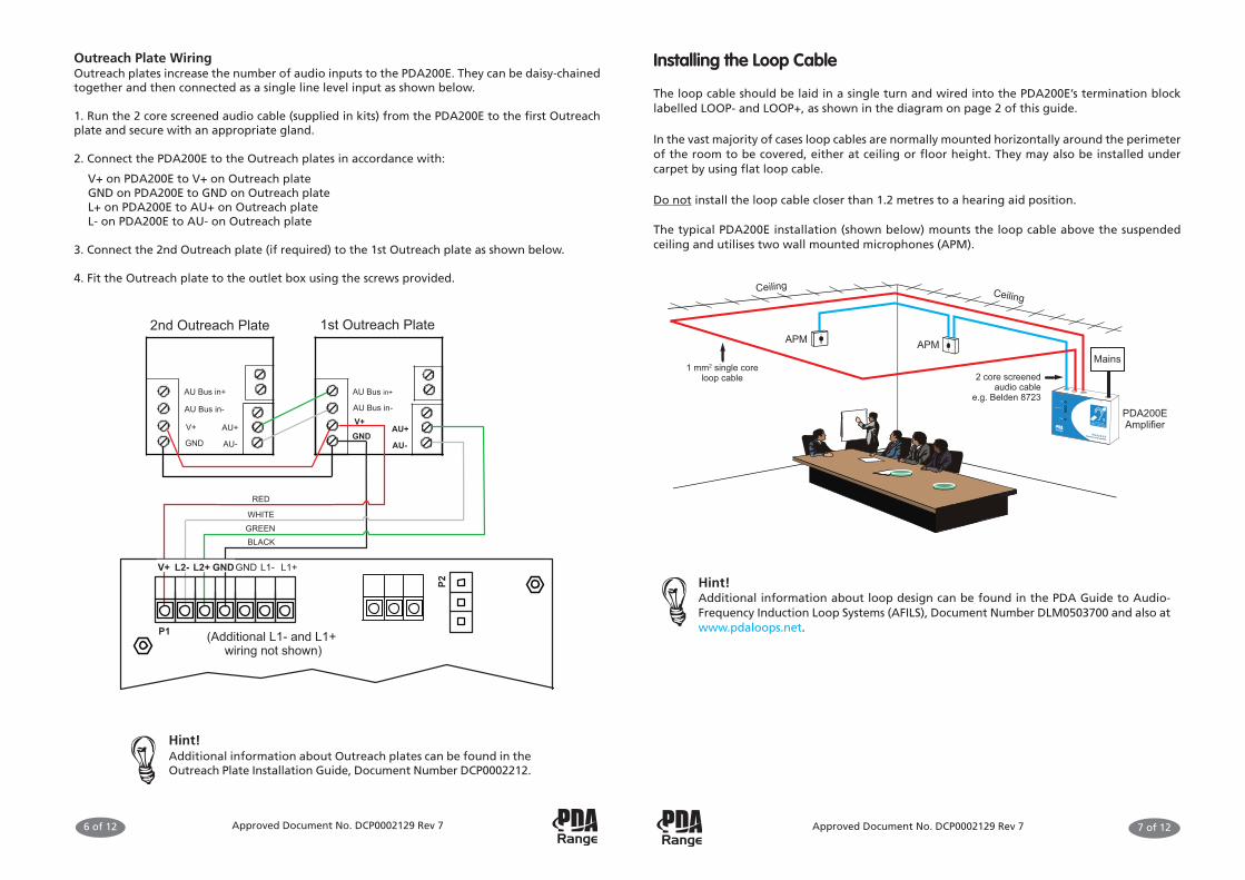
Installing the Loop Cable
The loop cable should be laid in a single turn and wired into the PDA200E’s termination blocklabelled LOOP- and LOOP+, as shown in the diagram on page 2 of this guide.
In the vast majority of cases loop cables are normally mounted horizontally around the perimeterof the room to be covered, either at ceiling or floor height. They may also be installed undercarpet by using flat loop cable.
Do not install the loop cable closer than 1.2 metres to a hearing aid position.
The typical PDA200E installation (shown below) mounts the loop cable above the suspendedceiling and utilises two wall mounted microphones (APM).
2 core screenedaudio cable
e.g. Belden 8723
1 mm2 single coreloop cable
PDA200EAmplifier
APM APM
Ceiling Ceiling
Mains
Hint!Additional information about loop design can be found in the PDA Guide to Audio-Frequency Induction Loop Systems (AFILS), Document Number DLM0503700 and also atwww.pdaloops.net.
Outreach Plate WiringOutreach plates increase the number of audio inputs to the PDA200E. They can be daisy-chainedtogether and then connected as a single line level input as shown below.
1. Run the 2 core screened audio cable (supplied in kits) from the PDA200E to the first Outreachplate and secure with an appropriate gland.
2. Connect the PDA200E to the Outreach plates in accordance with:
V+ on PDA200E to V+ on Outreach plateGND on PDA200E to GND on Outreach plateL+ on PDA200E to AU+ on Outreach plateL- on PDA200E to AU- on Outreach plate
3. Connect the 2nd Outreach plate (if required) to the 1st Outreach plate as shown below.
4. Fit the Outreach plate to the outlet box using the screws provided.
1st Outreach Plate2nd Outreach Plate
AU Bus in+
AU Bus in-
V+
GND
AU Bus in+
AU Bus in-V+GND
AU-
AU+
AU-
AU+P2
P1
L1- L1+GNDV+ L2- L2+ GND
RED
WHITEGREENBLACK
(Additional L1- and L1+ wiring not shown)
Approved Document No. DCP0002129 Rev 76 of 12
Hint!Additional information about Outreach plates can be found in theOutreach Plate Installation Guide, Document Number DCP0002212.


![ODOT- PDA intro.ppt [Read-Only] · PDA ConclusionsPDA Conclusions • PDA with CAPWAP evaluates capacity at low cost for driven piles, drilled shafts, & augercast piles • PDA gives](https://img.dokumen.tips/doc/110x75/5e80a08e0838cb51cc1301e3/odot-pda-introppt-read-only-pda-conclusionspda-conclusions-a-pda-with-capwap.jpg)