Embed Size (px)
Citation preview

Page 1
PD21406
"Here, Manufacture This!" Fusion 360 Drawings for Manufacturing Andrew De Leon Autodesk, Inc.
Description Drawings in Fusion 360 software has implemented a lot of new and exciting functionality this year. This class aims to introduce the newer capabilities—such as title blocks and templates, component versus body distinction, and multi-asset documentation—to those who need more than the out-of-the-box solution. We will cover this through a series of demonstrations using real-world title blocks and templates, dimensions, and Geometric Dimensioning and Tolerancing (GD&T) to create shop drawings ready for manufacture. With this, users will be able to apply what they’ve seen to get more out of their drawings in Fusion 360 software, and create drawings that are thorough, accurate, and tailored to their needs. This session features Fusion 360. Your AU Expert(s) Andrew de Leon is a senior principal user experience designer at Autodesk, Inc., with 20 years’ experience in the manufacturing industry and 11 years in user experience design. He has experience with AutoCAD software, AutoCAD Mechanical software, Inventor software, and Fusion 360 software. He’s passionate about manufacturing and design, and enjoys solving difficult problems.
Learning Objectives • Learn how to capitalize on multiple asset types to create drawings containing more
than just a component or assembly • Learn how to work with the browser for better control over components and bodies
in Drawings • Learn how to create templates from your existing drawings and add custom title
blocks • Learn how to create production-ready shop drawings, efficiently

Page 2
Contents
The Basics ............................................................................................................ 3Configuring Preferences ........................................................................................................ 3Creating Drawings ................................................................................................................. 3The Drawings Workspace ..................................................................................................... 4Editing Drawings .................................................................................................................... 5
Double-click ....................................................................................................................... 5Grip Edit ............................................................................................................................. 6Editing the BOM ................................................................................................................. 6
Updating Drawings ................................................................................................................ 6
The Browser, Multi-Asset Drawings and Exploded Views .............................. 7The Browser and Multi-Asset Drawings ................................................................................ 7
Creating Views and Parts Lists from existing references ................................................... 7Toggles .............................................................................................................................. 7Highlights ........................................................................................................................... 7Multi-Asset Drawings ......................................................................................................... 8
Exploded Views ..................................................................................................................... 8
Title Blocks and Templates ................................................................................ 9Default Title Blocks ................................................................................................................ 9Importing Custom Title Blocks ............................................................................................... 9Drawing Templates ................................................................................................................ 9
Dimensions and Symbols ................................................................................. 11Dimensions .......................................................................................................................... 11
Dimension Properties ....................................................................................................... 11Geometric Dimensioning and Tolerancing (GD&T) Symbols .............................................. 12
Inserting Special Characters ............................................................................................ 12
Coming Up: Multi-Sheet Drawings, Tables ..................................................... 13Multi-Sheet Drawings .......................................................................................................... 13Tables .................................................................................................................................. 14

Page 3
The Basics This section contains information on getting started with creating your first drawing in Fusion 360.
Configuring Preferences A set of drawing defaults can be configured in the Preferences section (User Profile drop down menu > Preferences). These settings will be applied to new drawings and can be overridden at the time of drawing creation, in the Create Drawing dialog or using the Annotation and Sheet Settings options within the drawings workspace. More information here.
DRAWINGS PREFERENCES
Creating Drawings Drawings can be created from one of many access points. With the design open, select: New Drawing from the File Menu or select Drawing from the Workspace Switcher. Alternatively, select one or more components to be documented and choose Create Drawing from the right click menu. A fourth way to create drawings would be using the right click menu on a design in the Data Panel. This, however, skips the Create Drawing dialog and jumps right into the Drawings workspace with a new drawing that takes the Standard and other values from the Preferences.

Page 4
The Drawings Workspace The user interface in the drawings is similar to the rest of Fusion 360. The screenshot below illustrates the major elements.
DRAWINGS WORKSPACE
Commands are categorized into different panels in the toolbar. Hover over each command to see information on its usage. Some commands can be initiated through a shortcut key that is listed next to it.
SHORTCUT KEY AND TOOLTIP
Dialogs and contextual right-click marking menus aid in working with the commands. Use the info button in the command dialog for more information on the features and some tips and tricks.
Drawing Views Four view types are available in Drawings – Base, Projected, Section and Detail. The base view can be created from the design or animation story boards (exploded views). Properties such as Orientation, Scale, Style, etc. can be edited in the accompanying command dialog for views.

Page 5
To create Auxiliary views or views in orientations other than the standard orthogonal and isometric orientations, create Named Views in the design. The Look At command is useful for this purpose. Named Views will be added to the Orientation list for base views.
NAMED VIEWS TO CAPTURE CUSTOM ORIENTATIONS
Rotating Views The Rotate command in the Modify Panel can be used to rotate one or more canvas entities. The Reference option is particularly useful in determining the angle at which an edge lies and making changes to it. Select the view and base point to access this option in the command dialog.
ROTATE BY REFERENCE
Editing Drawings Every drawing entity in the canvas supports one or more of the following edit operations.
Double-click Properties of Views, Hatches, Dimensions, Text, Symbols and Title Block can be edited using a double-click. This opens the command dialog or the in place text editor.

Page 6
Grip Edit Select an entity to view its grips. Pick the grip and move it around to make positional adjustments.
DIMENSION GRIP EDIT
Dimensions on projected / section views may become disassociated during Move if the view is constrained (aligned with the parent view). To prevent this, use the center grip on a view to move it. Associated annotations will follow.
Editing the BOM The Parts List values are derived from the design. To make changes to the Part Number and Description, edit the Properties of the component in the design. Item number can be adjusted using the Balloon Renumber Command.
BROWSER RIGHT CLICK MENU
Use the Output Parts List command in the Output Panel to export the Parts List in CSV format. This can be imported into Excel for further edits.
Updating Drawings Make necessary edits to the design and save. Back in the drawing, choose ‘Get Latest’ from the Quick Access Toolbar. Note: We can choose to not update the drawing to the latest version of the design. However, no other associations are supported (such as associating the drawing to version x of the design).

Page 7
The Browser, Multi-Asset Drawings and Exploded Views In this section we explore how we can leverage the Browser in the Drawings to create and manage complex drawings.
The Browser and Multi-Asset Drawings The Browser provides finer control on the view geometry allowing for quick toggles, much like the Model Browser. Launch Base View command in the drawing. In the accompanying Drawing View dialog, choose an appropriate representation (Model / Animation Storyboard). Once the base view has been placed, a corresponding reference node is added to the Browser tree. Expand the node to view all components/bodies in the structure.
Creating Views and Parts Lists from existing references Use the right click menu on a reference node to create a new view / parts list from the same reference.
BROWSER REFERENCE NODE RIGHT CLICK MENU
Toggles Browser operations affect all drawing entities that are created using that reference node. Use the light bulb next to bodies and components to toggle visibility in drawing views. Checkboxes next to components can be used to suppress/unsuppress them. A suppressed component is also removed from the parts list.
With complex geometry (such as T-Splines) and multiple views in the drawing, each toggle operation in the browser may be time consuming. To work around this, multi select (Shift+select or Ctrl/Cmd+select) components and use the options in the right click menu to apply toggles in a single command.
Highlights Selecting a browser node will highlight all drawing entities (views and parts lists) referencing it. Similarly, selecting a view or a parts list will highlight the corresponding browser node.

Page 8
BROWSER NODE HIGHLIGHT
Multi-Asset Drawings Drawings can contain references to the design as well as animation storyboards. The appropriate asset (Representation and Reference) can be chosen in the Base View command dialog. Alternatively, when creating drawings from the Design or Animation workspace, we can also select an open drawing, instead of creating a new one to work with.
Exploded Views Animation Storyboards can be set up to create exploded views in drawings. The end of the storyboard’s timeline will be used in the drawing. More information on exploded views here.

Page 9
Title Blocks and Templates In this section, we look at some of the newer features in drawings such as importing custom title blocks as well as creating drawing templates in Fusion.
Default Title Blocks A default title block for ASME and ISO standards is available in the drawings. The text attribute values can be edited using a double-click. The edit dialog also provides an option to insert an image. Note: When exporting a drawing as DWG from the output panel in the Drawings workspace, the image from the title block will also be exported. However, the image will be missing upon DWG export from A360. This is a current limitation.
Importing Custom Title Blocks An AutoCAD DWG containing a custom title block can be imported into a drawing. Once imported, it can be accessed from the Title Block menu. If attributes in the title block are set up as expected, a double-click will bring up the edit dialog, as with default title blocks, and the attribute values can be entered into the dialog. More information and guidelines on preparing the DWG here.
INSERT TITLE BLOCK
Drawing Templates Templates can be created from drawings in Fusion. To do this, choose Output Drawing Template from the Output panel and choose a location to save the template. All non-associated entities, Annotation and Sheet Settings will be saved to the template. At the time of drawing creation, this template can be chosen instead of the standard ASME and ISO templates. Templates in the same project as the design will be listed in the dropdown menu in the Create Drawing dialog. Use the Browse option to locate templates in other projects.
CREATE DRAWING FROM TEMPLATE

Page 10
Templates can be opened from the data panel and edited like drawings. Commands to create views, parts list, etc. are not available in the Templates workspace.
TEMPLATES WORKSPACE
Use the Data Panel’s Projects and Folders to organize templates.

Page 11
Dimensions and Symbols Drawings supports a variety of dimensions and mechanical symbols. In this section we will take a closer look these options.
Dimensions The Dimensions panel encompasses a number of commands. The default is a smart Dimension command that is able to dimension between points or on edges to create linear, radial, angular dimensions, etc. Selecting an existing dimension with this command will chain new dimensions to it. Each of the primitive dimension types are also available in the flyout menu which provide better control. Baseline and Chain Dimension commands allow for faster dimensioning.
THE DIMENSIONS PANEL
Since Drawings don’t have Drafting abilities yet, guide lines can be created using Dimensions, Centerlines and Center Marks. As an example, the Angular Dimension command has been used to create a dimension whose snap points are used to create a precise aligned section:
SECTIONING USING AN ANGULAR DIMENSION AS GUIDE
Dimension Properties Double-click a dimension to open the Dimension properties dialog where Tolerances, Alternate units, Representation, Inspection labels, etc. can be applied. A list of general and standard specific symbols are available for insertion within the dialog. Precision, Tolerances and Alternate unit overrides can be cleared using the Restore Defaults

Page 12
command. Select one or more dimensions with overrides and use the contextual marking menu to access this command.
RESTORE DEFAULTS TO CLEAR DIMENSION OVERRIDES
Geometric Dimensioning and Tolerancing (GD&T) Symbols Drawings support Datum ID, Feature Control Frame and Surface Texture commands. They can be placed on straight/circular view edges, dimensions, centerlines and center marks. Datum ID and Surface Texture symbols can also be placed on existing Feature Control Frames. Surface attachment type is also available in ISO drawings. After picking a view edge, use the contextual marking menu to switch from the default Edge attachment to Surface. More information on drawing symbols here.
Inserting Special Characters A Symbol Palette is available in the Edit dialogs for Text, Dimension, Datum ID and Feature Control Frame. This includes a list of general symbols and standard specific GD&T symbols.
SYMBOL PALETTE WITH SPECIAL CHARACTERS
In Place Text Editors (IPE) and Command Dialogs are able to handle Unicode characters. To use symbols that are not available in the Symbol Palette, copy-paste the character from any source into a dialog / IPE. Alternatively, the character’s code point can be typed. Eg: To get the clockwise rotation arrow (↷), key in \U+21B7.

Page 13
Coming Up: Multi-Sheet Drawings, Tables This section serves as a brief introduction to some of the upcoming features in Drawings. As the these are currently under development, there may be minor changes in the functionality when it is released.
Multi-Sheet Drawings One of the most anticipated features in drawings is the ability to create multiple sheets in the same file. With this, we can create multi-sheet drawings and templates with each sheet configured individually.
SHEET SET BAR
Add, remove, rename, reorder sheets and export individual sheets from the Sheet Set Bar.
SHEET RIGHT CLICK MENU
With multiple sheets in the drawings, badges help identify the sheets that are out of date with the design or contain disassociated dimensions. When a design change is made and ‘Get Latest’ is run on the drawing, the active sheet is updated. All other sheets requiring an update will be badged and will be updated automatically upon switching to the sheet.
Page 14
BADGES INDICATE OUT OF DATE SHEETS
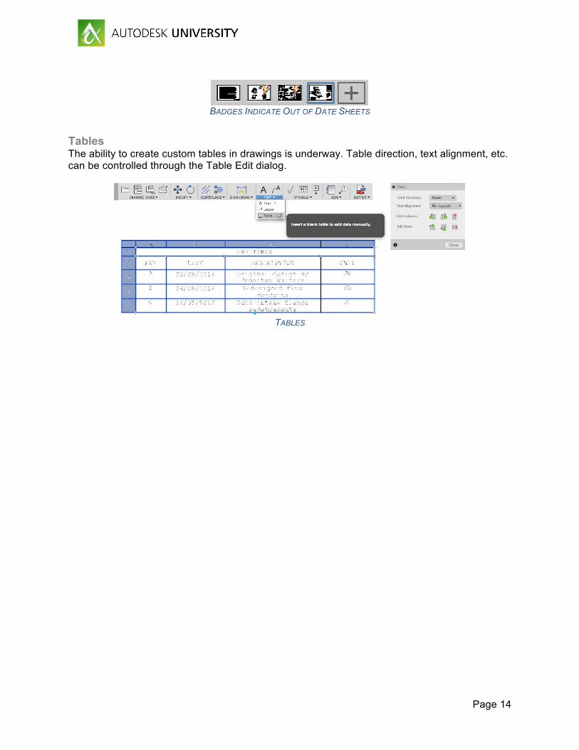
Tables The ability to create custom tables in drawings is underway. Table direction, text alignment, etc. can be controlled through the Table Edit dialog.
TABLES