Embed Size (px)
Citation preview
FCC ID: A3LSMG532M
HAC (RF EMISSIONS) TEST REPORT
Reviewed by:
Quality Manager
Filename: Test Dates: DUT Type: Page 1 of 60
0Y1608301531-R2.A3L 08/29/2016 Portable Handset
© 2016 PCTEST Engineering Laboratory, Inc. REV 3.1.M 07/05/2016
© 2016 PCTEST Engineering Laboratory, Inc. All rights reserved. Unless otherwise specified, no part of this report may be reproduced or utilized in any part, form or by any means, electronic or mechanical, including photocopying and microfilm, without permission in writing from PCTEST Engineering Laboratory, Inc. If you have any questions about this international copyright or have an enquiry about obtaining additional rights to this report or assembly of contents thereof, please contact [email protected].
Applicant Name: Date of Testing: Samsung Electronics Co., Ltd. 08/29/2016 129, Samsung-ro, Maetan dong, Test Site/Location: Yeongtong-gu, Suwon-si PCTEST Lab, Columbia, MD, USA Gyeonggi-do 16677, Korea Test Report Serial No.: 0Y1608301531-R2.A3L
FCC ID: A3LSMG532M
APPLICANT: SAMSUNG ELECTRONICS CO., LTD.
Scope of Test: RF Emissions Testing Application Type: Certification FCC Rule Part(s): CFR §20.19(b) HAC Standard: ANSI C63.19-2011 DUT Type: Portable Handset Model(s): SM-G532M, SM-G532MT, SM-G532M/DS Test Device Serial No.: Pre-Production Sample [S/N: 02130]
C63.19-2011 HAC Category: M3 (RF EMISSIONS CATEGORY)
Note: This revised Test Report (S/N: 0Y1608301531-R2.A3L) supersedes and replaces the previously issued test report on the same subject device for the same type of testing as indicated. Please discard or destroy the previously issued test report(s) and dispose of it accordingly. This wireless portable device has been shown to be hearing-aid compatible under the above rated category, specified in ANSI/IEEE Std. C63.19-2011 and has been tested in accordance with the specified measurement procedures. Hearing-Aid Compatibility is based on the assumption that all production units will be designed electrically identical to the device tested in this report. Test results reported herein relate only to the item(s) tested. I attest to the accuracy of data. All measurements reported herein were performed by me or were made under my supervision and are correct to the best of my knowledge and belief. I assume full responsibility for the completeness of these measurements and vouch for the qualifications of all persons taking them.
PCTEST ENGINEERING LABORATORY, INC. 7185 Oakland Mills Road, Columbia, MD 21046 USA
Tel. 410.290.6652 / Fax 410.290.6654 http://www.pctestlab.com
HEARING AID COMPATIBILITY

FCC ID: A3LSMG532M
HAC (RF EMISSIONS) TEST REPORT
Reviewed by:
Quality Manager
Filename: Test Dates: DUT Type: Page 2 of 60
0Y1608301531-R2.A3L 08/29/2016 Portable Handset
© 2016 PCTEST Engineering Laboratory, Inc. REV 3.1.M 07/05/2016
© 2016 PCTEST Engineering Laboratory, Inc. All rights reserved. Unless otherwise specified, no part of this report may be reproduced or utilized in any part, form or by any means, electronic or mechanical, including photocopying and microfilm, without permission in writing from PCTEST Engineering Laboratory, Inc. If you have any questions about this international copyright or have an enquiry about obtaining additional rights to this report or assembly of contents thereof, please contact [email protected].
T A B L E O F C O N T E N T S
1. INTRODUCTION ............................................................................................................................. 3
2. DUT DESCRIPTION ........................................................................................................................ 4
3. ANSI/IEEE C63.19 PERFORMANCE CATEGORIES..................................................................... 6
4. SYSTEM SPECIFICATIONS ........................................................................................................... 7
5. TEST PROCEDURE ..................................................................................................................... 12
6. SYSTEM CHECK .......................................................................................................................... 14
7. MODULATION INTERFERENCE FACTOR .................................................................................. 17
8. RF CONDUCTED POWER MEASUREMENTS ............................................................................ 20
9. JUSTIFICATION OF HELD TO EAR MODES TESTED ............................................................... 22
10. OVERALL MEASUREMENT SUMMARY ..................................................................................... 23
11. EQUIPMENT LIST ......................................................................................................................... 25
12. MEASUREMENT UNCERTAINTY ................................................................................................ 26
13. TEST DATA ................................................................................................................................... 27
14. CALIBRATION CERTIFICATES .................................................................................................... 32
15. CONCLUSION ............................................................................................................................... 55
16. REFERENCES .............................................................................................................................. 56
17. TEST PHOTOGRAPHS ................................................................................................................ 58

FCC ID: A3LSMG532M
HAC (RF EMISSIONS) TEST REPORT
Reviewed by:
Quality Manager
Filename: Test Dates: DUT Type: Page 3 of 60
0Y1608301531-R2.A3L 08/29/2016 Portable Handset
© 2016 PCTEST Engineering Laboratory, Inc. REV 3.1.M 07/05/2016
© 2016 PCTEST Engineering Laboratory, Inc. All rights reserved. Unless otherwise specified, no part of this report may be reproduced or utilized in any part, form or by any means, electronic or mechanical, including photocopying and microfilm, without permission in writing from PCTEST Engineering Laboratory, Inc. If you have any questions about this international copyright or have an enquiry about obtaining additional rights to this report or assembly of contents thereof, please contact [email protected].
1 . I N T R O D U C T I O N
On July 10, 2003, the Federal Communications Commission (FCC) adopted new rules requiring wireless manufacturers and service providers to provide digital wireless phones that are compatible with hearing aids. The FCC has modified the exemption for wireless phones under the Hearing Aid Compatibility Act of 1998 (HAC Act) in WT Docket 01-309 RM-8658
1 to extend the benefits of wireless telecommunications to
individuals with hearing disabilities. These benefits encompass business, social and emergency communications, which increase the value of the wireless network for everyone. An estimated more than 10% of the population in the United States show signs of hearing impairment and of that fraction, almost 80% use hearing aids. Approximately 500 million people worldwide suffer from hearing loss. Compatibility Tests Involved: The standard calls for wireless communications devices to be measured for:
RF Electric-field emissions T-coil mode, magnetic-signal strength in the audio band T-coil mode, magnetic-signal frequency response through the audio band T-coil mode, magnetic-signal and noise articulation index
The hearing aid must be measured for:
RF immunity in microphone mode RF immunity in T-coil mode
In the following tests and results, this report includes the evaluation for a wireless communications device.
Figure 1-1 Hearing Aid in-vitu
1 FCC Rule & Order, WT Docket 01-309 RM-8658
FCC ID: A3LSMG532M
HAC (RF EMISSIONS) TEST REPORT
Reviewed by:
Quality Manager
Filename: Test Dates: DUT Type: Page 4 of 60
0Y1608301531-R2.A3L 08/29/2016 Portable Handset
© 2016 PCTEST Engineering Laboratory, Inc. REV 3.1.M 07/05/2016
© 2016 PCTEST Engineering Laboratory, Inc. All rights reserved. Unless otherwise specified, no part of this report may be reproduced or utilized in any part, form or by any means, electronic or mechanical, including photocopying and microfilm, without permission in writing from PCTEST Engineering Laboratory, Inc. If you have any questions about this international copyright or have an enquiry about obtaining additional rights to this report or assembly of contents thereof, please contact [email protected].
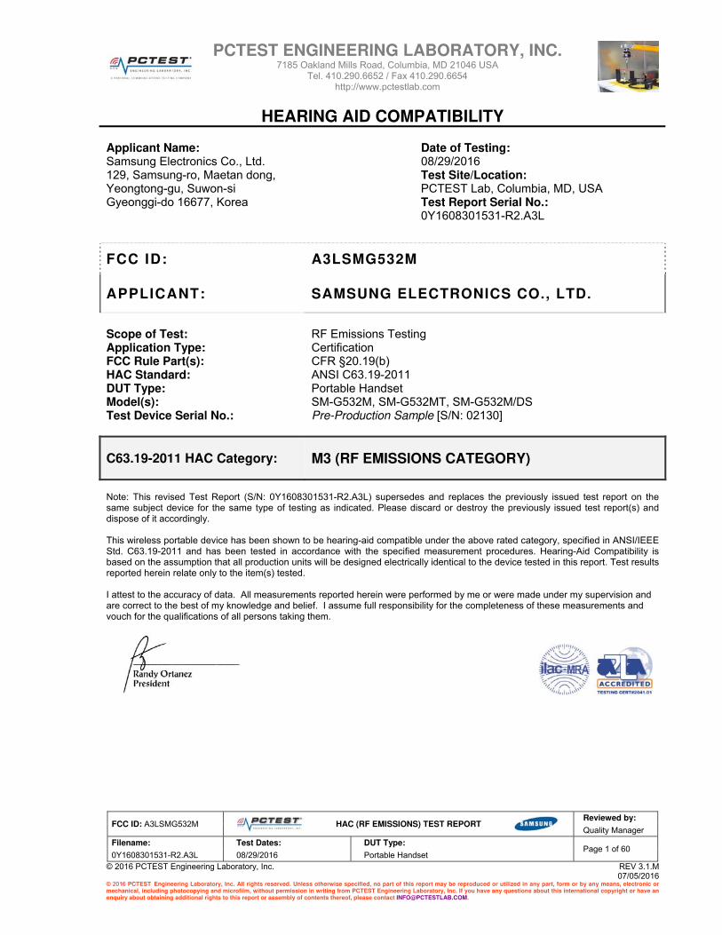
2 . D U T D E S C R I P T I O N
FCC ID: A3LSMG532M
Manufacturer: Samsung Electronics Co., Ltd.
129, Samsung-ro, Maetan dong,
Yeongtong-gu, Suwon-si
Gyeonggi-do 16677, Korea
Model(s): SM-G532M, SM-G532MT, SM-G532M/DS
Serial Number: 02130
Antenna Configurations: Internal Antenna
HAC Test Configurations: GSM 850, 128, 190, 251, BT Off, WLAN Off, LTE Off
GSM 1900, 512, 661, 810, BT Off, WLAN Off, LTE Off
DUT Type: Portable Handset
Air‐Interface Band (MHz)
Type Transport HAC Tested Simultaneous But Not Tested
Voice over Digital Transport
OTT Capability
Additional GSM Power Reduction
850
1900
GPRS/EDGE DT No Yes: WIFI or BT Yes No
850
1700
1900
HSPA DT No Yes: WIFI or BT Yes N/A
700 (B17)
850 (B5)
1700 (B4)
1900 (B2)
2450
BT 2450 DT No Yes: GSM, UMTS, or LTE N/A N/A
N/ALTE (FDD) DT No Yes: WIFI or BT Yes
Type TransportVO = Voice OnlyDT = Digital Data ‐ Not intended for CMRS ServiceVD = CMRS and Data Transport
Notes:
1. Evaluated for MIF and low‐power exemption.
N/AWIFI VD No1 Yes: GSM, UMTS, or LTE Yes
N/AUMTS
VD No¹ Yes: WIFI or BT N/A
NoGSM
VO Yes Yes: WIFI or BT N/A
Table 2-1 SM-G532M and SM-G532M/DS HAC Air Interfaces

FCC ID: A3LSMG532M
HAC (RF EMISSIONS) TEST REPORT
Reviewed by:
Quality Manager
Filename: Test Dates: DUT Type: Page 5 of 60
0Y1608301531-R2.A3L 08/29/2016 Portable Handset
© 2016 PCTEST Engineering Laboratory, Inc. REV 3.1.M 07/05/2016
© 2016 PCTEST Engineering Laboratory, Inc. All rights reserved. Unless otherwise specified, no part of this report may be reproduced or utilized in any part, form or by any means, electronic or mechanical, including photocopying and microfilm, without permission in writing from PCTEST Engineering Laboratory, Inc. If you have any questions about this international copyright or have an enquiry about obtaining additional rights to this report or assembly of contents thereof, please contact [email protected].
Air‐Interface Band (MHz)
Type Transport HAC Tested Simultaneous But Not Tested
Voice over Digital Transport
OTT Capability
Additional GSM Power Reduction
850
1900
GPRS/EDGE DT No Yes: WIFI or BT Yes No
850
1700
1900
HSPA DT No Yes: WIFI or BT Yes N/A
850 (B5)
1700 (B4)
1900 (B2)
2450
BT 2450 DT No Yes: GSM, UMTS, or LTE N/A N/A
N/ALTE (FDD) DT No Yes: WIFI or BT Yes
Type TransportVO = Voice OnlyDT = Digital Data ‐ Not intended for CMRS ServiceVD = CMRS and Data Transport
Notes:
1. Evaluated for MIF and low‐power exemption.2. No associated T‐coil measurement has been made in accordance with the guidance issued by OET in KDB publication 285076 D02 T‐Coil testing for CMRS IP.
N/AWIFI VD No¹ ² Yes: GSM, UMTS, or LTE Yes
N/AUMTS
VD No¹ Yes: WIFI or BT N/A
NoGSM
VO Yes Yes: WIFI or BT N/A
Table 2-2: SM-G532MT HAC Air Interfaces

FCC ID: A3LSMG532M
HAC (RF EMISSIONS) TEST REPORT
Reviewed by:
Quality Manager
Filename: Test Dates: DUT Type: Page 6 of 60
0Y1608301531-R2.A3L 08/29/2016 Portable Handset
© 2016 PCTEST Engineering Laboratory, Inc. REV 3.1.M 07/05/2016
© 2016 PCTEST Engineering Laboratory, Inc. All rights reserved. Unless otherwise specified, no part of this report may be reproduced or utilized in any part, form or by any means, electronic or mechanical, including photocopying and microfilm, without permission in writing from PCTEST Engineering Laboratory, Inc. If you have any questions about this international copyright or have an enquiry about obtaining additional rights to this report or assembly of contents thereof, please contact [email protected].
3 . A N S I / I E E E C 6 3 . 1 9 P E R F O R M A N C E C A T E G O R I E S
I. RF EMISSIONS The ANSI Standard presents performance requirements for acceptable interoperability of hearing aids with wireless communications devices. When these parameters are met, a hearing aid operates acceptably in close proximity to a wireless communications device.
Category Telephone RF Parameters
Near field Category E-field emissions
CW dB(V/m)
f < 960 MHz
M1 50 to 55
M2 45 to 50
M3 40 to 45
M4 < 40
f > 960 MHz
M1 40 to 45
M2 35 to 40
M3 30 to 35
M4 < 30
Table 3-1 WD near-field categories as defined in ANSI C63.19-2011

FCC ID: A3LSMG532M
HAC (RF EMISSIONS) TEST REPORT
Reviewed by:
Quality Manager
Filename: Test Dates: DUT Type: Page 7 of 60
0Y1608301531-R2.A3L 08/29/2016 Portable Handset
© 2016 PCTEST Engineering Laboratory, Inc. REV 3.1.M 07/05/2016
© 2016 PCTEST Engineering Laboratory, Inc. All rights reserved. Unless otherwise specified, no part of this report may be reproduced or utilized in any part, form or by any means, electronic or mechanical, including photocopying and microfilm, without permission in writing from PCTEST Engineering Laboratory, Inc. If you have any questions about this international copyright or have an enquiry about obtaining additional rights to this report or assembly of contents thereof, please contact [email protected].
4 . S Y S T E M S P E C I F I C A T I O N S
ER3DV6 E-Field Probe Description
Construction: One dipole parallel, two dipoles normal to probe axis
Built-in shielding against static charges
Figure 4-1
E-field Free-space Probe
Calibration: In air from 100 MHz to 3.0 GHz (absolute accuracy ±6.0%, k=2)
Frequency: 100 MHz to > 6 GHz; Linearity: ± 0.2 dB (100 MHz to 3 GHz)
Directivity ± 0.2 dB in air (rotation around probe axis) ± 0.4 dB in air (rotation normal to probe axis)
Dynamic Range 2 V/m to > 1000 V/m (M3 or better device readings fall well below diode compression point)
Linearity: ± 0.2 dB Dimensions Overall length: 330 mm (Tip: 16 mm)
Tip diameter: 8 mm (Body: 12 mm) Distance from probe tip to dipole centers: 2.5 mm
Probe Tip Description
HAC field measurements take place in the close near field with high gradients. Increasing the measuring distance from the source will generally decrease the measured field values (in case of the validation dipole approx. 10% per mm). The electric field probes have an irregular internal geometry because it is physically not possible to have the 3 orthogonal sensors situated with the same center. The effect of the different sensor centers is accounted for in the HAC uncertainty budget ("sensor displacement"). Their geometric center is at 2.5mm from the tip, and the element ends are 1.1mm closer to the tip.
The antistatic shielding inside the probe is connected to the probe connector case.

FCC ID: A3LSMG532M
HAC (RF EMISSIONS) TEST REPORT
Reviewed by:
Quality Manager
Filename: Test Dates: DUT Type: Page 8 of 60
0Y1608301531-R2.A3L 08/29/2016 Portable Handset
© 2016 PCTEST Engineering Laboratory, Inc. REV 3.1.M 07/05/2016
© 2016 PCTEST Engineering Laboratory, Inc. All rights reserved. Unless otherwise specified, no part of this report may be reproduced or utilized in any part, form or by any means, electronic or mechanical, including photocopying and microfilm, without permission in writing from PCTEST Engineering Laboratory, Inc. If you have any questions about this international copyright or have an enquiry about obtaining additional rights to this report or assembly of contents thereof, please contact [email protected].
Instrumentation Chain
Equation 1
Probe Response to Frequency
The E-field sensors have inherently a very flat frequency response. They are calibrated with a number of frequencies resulting in a common calibration factor, with the frequency behavior documented in the calibration certificate (See also below).
Figure 4-2 E-Field Probe Frequency Response
FCC ID: A3LSMG532M
HAC (RF EMISSIONS) TEST REPORT
Reviewed by:
Quality Manager
Filename: Test Dates: DUT Type: Page 9 of 60
0Y1608301531-R2.A3L 08/29/2016 Portable Handset
© 2016 PCTEST Engineering Laboratory, Inc. REV 3.1.M 07/05/2016
© 2016 PCTEST Engineering Laboratory, Inc. All rights reserved. Unless otherwise specified, no part of this report may be reproduced or utilized in any part, form or by any means, electronic or mechanical, including photocopying and microfilm, without permission in writing from PCTEST Engineering Laboratory, Inc. If you have any questions about this international copyright or have an enquiry about obtaining additional rights to this report or assembly of contents thereof, please contact [email protected].
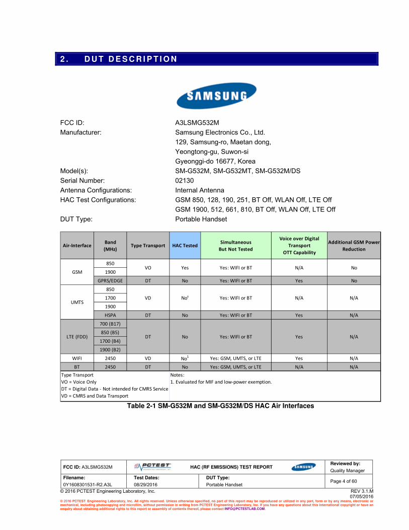
SPEAG Robotic System
E-field measurements are performed using the DASY5 automated dosimetric assessment system. The DASY5 is made by Schmid & Partner Engineering AG (SPEAG) in Zurich, Switzerland and consists of high precision robotics system (Staubli), robot controller, Intel CORE i7 computer, near-field probe, probe alignment sensor, and the HAC phantom. The robot is a six-axis industrial robot performing precise movements to position the probe to the location (points) of maximum electromagnetic field (EMF).
Figure 4-3 SPEAG Robotic System
System Hardware
A cell controller system contains the power supply, robot controller, teach pendant (Joystick), and a remote control used to drive the robot motors. The PC consists of the computer with operating system and RF Measurement Software DASY5 v52.8 (with HAC Extension), A/D interface card, monitor, mouse, and keyboard. The Staubli Robot is connected to the cell controller to allow software manipulation of the robot. A data acquisition electronic (DAE) circuit that performs the signal amplification, signal multiplexing, AD-conversion, offset measurements, mechanical surface detection, collision detection, etc. is connected to the Electro-optical coupler (EOC). The EOC performs the conversion from the optical into digital electric signal of the DAE and transfers data to the PC plug-in card.

FCC ID: A3LSMG532M
HAC (RF EMISSIONS) TEST REPORT
Reviewed by:
Quality Manager
Filename: Test Dates: DUT Type: Page 10 of 60
0Y1608301531-R2.A3L 08/29/2016 Portable Handset
© 2016 PCTEST Engineering Laboratory, Inc. REV 3.1.M 07/05/2016
© 2016 PCTEST Engineering Laboratory, Inc. All rights reserved. Unless otherwise specified, no part of this report may be reproduced or utilized in any part, form or by any means, electronic or mechanical, including photocopying and microfilm, without permission in writing from PCTEST Engineering Laboratory, Inc. If you have any questions about this international copyright or have an enquiry about obtaining additional rights to this report or assembly of contents thereof, please contact [email protected].
System Electronics
The DAE consists of a highly sensitive electrometer-grade preamplifier with auto-zeroing, a channel and gain-switching multiplexer, a fast 16 bit AD-converter and a command decoder and control logic unit. Transmission to the PC-card is accomplished through an optical downlink for data and status information and an optical uplink for commands and clock lines. The mechanical probe mounting device includes two different sensor systems for frontal and sidewise probe contacts. They are also used for mechanical surface detection and probe collision detection. The robot uses its own controller with a built in VME-bus computer.
Figure 4-4
SPEAG Robotic System Diagram
DASY5 Instrumentation Chain
The first step of the evaluation is a linearization of the filtered input signal to account for the compression characteristics of the detector diode. The compensation depends on the input signal, the diode type and the DC-transmission factor from the diode to the evaluation electronics. If the exciting field is pulsed, the crest factor of the signal must be known to correctly compensate for peak power. The formula for each channel can be given as:

FCC ID: A3LSMG532M
HAC (RF EMISSIONS) TEST REPORT
Reviewed by:
Quality Manager
Filename: Test Dates: DUT Type: Page 11 of 60
0Y1608301531-R2.A3L 08/29/2016 Portable Handset
© 2016 PCTEST Engineering Laboratory, Inc. REV 3.1.M 07/05/2016
© 2016 PCTEST Engineering Laboratory, Inc. All rights reserved. Unless otherwise specified, no part of this report may be reproduced or utilized in any part, form or by any means, electronic or mechanical, including photocopying and microfilm, without permission in writing from PCTEST Engineering Laboratory, Inc. If you have any questions about this international copyright or have an enquiry about obtaining additional rights to this report or assembly of contents thereof, please contact [email protected].
The measurement/integration time per point, as specified by the system manufacturer is >500ms. The signal response time is evaluated as the time required by the system to reach 90% of the expected final value after an on/off switch of the power source with an integration time of 500ms and a probe response time of <5 ms. In the current implementation, DASY5 waits longer than 100ms after having reached the grid point before starting a measurement, i.e., the response time uncertainty is negligible. If the device under test does not emit a CW signal, the integration time applied to measure the electric field at a specific point may introduce additional uncertainties due to the discretization. The tolerances for the different systems had the worst-case of 2.6%.

FCC ID: A3LSMG532M
HAC (RF EMISSIONS) TEST REPORT
Reviewed by:
Quality Manager
Filename: Test Dates: DUT Type: Page 12 of 60
0Y1608301531-R2.A3L 08/29/2016 Portable Handset
© 2016 PCTEST Engineering Laboratory, Inc. REV 3.1.M 07/05/2016
© 2016 PCTEST Engineering Laboratory, Inc. All rights reserved. Unless otherwise specified, no part of this report may be reproduced or utilized in any part, form or by any means, electronic or mechanical, including photocopying and microfilm, without permission in writing from PCTEST Engineering Laboratory, Inc. If you have any questions about this international copyright or have an enquiry about obtaining additional rights to this report or assembly of contents thereof, please contact [email protected].
5 . T E S T P R O C E D U R E
I. RF EMISSIONS
Figure 5-1 RF Emissions Flow Chart
Per 5.5.1.2 (a-c)
Per 5.5.1.2 (d-f)
Per 5.5.1.2 (g-h) & 5.5.1.3
Per 5.5.1.2 (i-j)

FCC ID: A3LSMG532M
HAC (RF EMISSIONS) TEST REPORT
Reviewed by:
Quality Manager
Filename: Test Dates: DUT Type: Page 13 of 60
0Y1608301531-R2.A3L 08/29/2016 Portable Handset
© 2016 PCTEST Engineering Laboratory, Inc. REV 3.1.M 07/05/2016
© 2016 PCTEST Engineering Laboratory, Inc. All rights reserved. Unless otherwise specified, no part of this report may be reproduced or utilized in any part, form or by any means, electronic or mechanical, including photocopying and microfilm, without permission in writing from PCTEST Engineering Laboratory, Inc. If you have any questions about this international copyright or have an enquiry about obtaining additional rights to this report or assembly of contents thereof, please contact [email protected].
Test Setup
Figure 5-2 E-Field Emissions Test Setup Diagram (See Test
Photographs for actual WD scan grid overlay)
Figure 5-3
HAC Phantom
RF Emissions Test Procedure: The following illustrate a typical RF emissions test scan over a wireless communications device:
1. Proper operation of the field probe, probe measurement system, other instrumentation, and the positioning system was confirmed.
2. WD is positioned in its intended test position, acoustic output point of the device perpendicular to
the field probe.
3. The WD operation for maximum rated RF output power was configured and confirmed with the base station simulator, at the test channel and other normal operating parameters as intended for the test. The battery was ensured to be fully charged before each test.
4. The center sub-grid was centered over the center of the acoustic output (also audio band
magnetic output, if applicable). The WD audio output was positioned tangent (as physically possible) to the measurement plane.
5. A surface calibration was performed before each setup change to ensure repeatable spacing and
proper maintenance of the measurement plane using the HAC Phantom.
6. The measurement system measured the field strength at the reference location.
7. Measurements at 2mm or 5mm increments in the 5 x 5 cm region were performed at a distance 15 mm from the center point of the probe measurement element to the WD. A 360
o rotation about
the azimuth axis at the maximum interpolated position was measured. For the worst-case condition, the peak reading from this rotation was used in re-evaluating the HAC category.
8. The system performed a drift evaluation by measuring the field at the reference location. If the
power drift deviated by more than 5%, the HAC test and drift measurements were repeated.

FCC ID: A3LSMG532M
HAC (RF EMISSIONS) TEST REPORT
Reviewed by:
Quality Manager
Filename: Test Dates: DUT Type: Page 14 of 60
0Y1608301531-R2.A3L 08/29/2016 Portable Handset
© 2016 PCTEST Engineering Laboratory, Inc. REV 3.1.M 07/05/2016
© 2016 PCTEST Engineering Laboratory, Inc. All rights reserved. Unless otherwise specified, no part of this report may be reproduced or utilized in any part, form or by any means, electronic or mechanical, including photocopying and microfilm, without permission in writing from PCTEST Engineering Laboratory, Inc. If you have any questions about this international copyright or have an enquiry about obtaining additional rights to this report or assembly of contents thereof, please contact [email protected].
6 . S Y S T E M C H E C K
I. System Check Parameters The input signal was an un-modulated continuous wave. The following points were taken into consideration in performing this check: � Average Input Power P = 100mW RMS (20dBm RMS) after adjustment for return loss � The test fixture must meet the 2 wavelength separation criterion � The proper measurement of the 15 mm probe to dipole separation, which is measured from top
surface of the dipole to the calibration reference point of the sensor, defined by the probe manufacturer is shown in the following diagram:
Figure 6-1
Separation Distance from Dipole to Field Probe RF power was recorded using both an average reading meter and a peak reading meter. Readings of the probe are provided by the measurement system. To assure proper operation of the near-field measurement probe the input power to the dipole shall be commensurate with the full rated output power of the wireless device [e.g. - for a cellular phone wireless device the average peak antenna input power will be on the order of 100mW (20dBm) RMS] after adjustment for any mismatch.
II. Validation Procedure A dipole antenna meeting the requirements given in C63.19 was placed in the position normally occupied by the WD. The length of the dipole was scanned, and the average peak value was recorded.
Measurement of CW
Using the near-field measurement system, scan the antenna over the radiating dipole and record the greatest field reading observed. Due to the nature of E-fields about free-space dipoles, the two E-field peaks measured over the dipole are averaged to compensate for non-parallelity of the setup (see manufacturer method on dipole calibration certificates, page 2). Field strength measurements shall be made only when the probe is stationary.
15 mm
Dipole arm
Manufactures Probe Calibration Reference point
Top surface of dipole
Center of dipole
E-field probe Housing

FCC ID: A3LSMG532M
HAC (RF EMISSIONS) TEST REPORT
Reviewed by:
Quality Manager
Filename: Test Dates: DUT Type: Page 15 of 60
0Y1608301531-R2.A3L 08/29/2016 Portable Handset
© 2016 PCTEST Engineering Laboratory, Inc. REV 3.1.M 07/05/2016
© 2016 PCTEST Engineering Laboratory, Inc. All rights reserved. Unless otherwise specified, no part of this report may be reproduced or utilized in any part, form or by any means, electronic or mechanical, including photocopying and microfilm, without permission in writing from PCTEST Engineering Laboratory, Inc. If you have any questions about this international copyright or have an enquiry about obtaining additional rights to this report or assembly of contents thereof, please contact [email protected].
RF power was recorded using both an average and a peak power reading meter.
Signal
GeneratorAmplifier
Directional Coupler
Power Meter
Reference
Output Power Meter
Reference Dipole
Figure 6-2
Setup for Desired Output Power to Dipole
Signal
GeneratorAmplifier
Directional Coupler
Power Meter
Reference
Output Power Meter
Reference Dipole
Figure 6-3
Setup to Dipole Using this setup configuration, the signal generator was adjusted for the desired output power (100mW) at a specified frequency. The reference power from the coupled port of the directional coupler is recorded. Next, the output cable is connected to the reference dipole, as shown in Figure 6-3. The input signal level was adjusted until the reference power from the coupled port of the directional coupler was the same as previously recorded, to compensate for the impedance mismatch between the output cable and the reference dipole. To assure proper operation of the near-field measurement probe the input power to the reference dipole was verified to the full rated output power of the wireless device. The dipole was secured in a holder in a manner to meet the 20 dB reflection. The near-field measurement probe was positioned over the dipole. The antenna was scanned over the appropriate sized area to cover the dipole from end to end. SPEAG uses 2D interpolation algorithms between the measured points. Please see below two dimensional plots showing that the interpolated values interpolate smoothly between 5mm steps for a free-space RF dipole:
Figure 6-4
2-D Raw Data from scan along dipole axis
Figure 6-5 2-D Interpolated points from scan along dipole axis
Figure 6-6
2-D Raw Data from scan along transverse axis Figure 6-7
2-D Interpolated points from scan along transverse axis

FCC ID: A3LSMG532M
HAC (RF EMISSIONS) TEST REPORT
Reviewed by:
Quality Manager
Filename: Test Dates: DUT Type: Page 16 of 60
0Y1608301531-R2.A3L 08/29/2016 Portable Handset
© 2016 PCTEST Engineering Laboratory, Inc. REV 3.1.M 07/05/2016
© 2016 PCTEST Engineering Laboratory, Inc. All rights reserved. Unless otherwise specified, no part of this report may be reproduced or utilized in any part, form or by any means, electronic or mechanical, including photocopying and microfilm, without permission in writing from PCTEST Engineering Laboratory, Inc. If you have any questions about this international copyright or have an enquiry about obtaining additional rights to this report or assembly of contents thereof, please contact [email protected].
III. System Check Results
Validation Results
835 1082 20.0 112.3 106.8 5.1%
1880 1064 20.0 91.0 89.6 1.6%
%
Deviation
Target
Field
(V/m)
Input
Power
(dBm)
E-field
Result
(V/m)
Dipole S/NFrequency
(MHz)
Figure 6-8
System Check Setup

FCC ID: A3LSMG532M
HAC (RF EMISSIONS) TEST REPORT
Reviewed by:
Quality Manager
Filename: Test Dates: DUT Type: Page 17 of 60
0Y1608301531-R2.A3L 08/29/2016 Portable Handset
© 2016 PCTEST Engineering Laboratory, Inc. REV 3.1.M 07/05/2016
© 2016 PCTEST Engineering Laboratory, Inc. All rights reserved. Unless otherwise specified, no part of this report may be reproduced or utilized in any part, form or by any means, electronic or mechanical, including photocopying and microfilm, without permission in writing from PCTEST Engineering Laboratory, Inc. If you have any questions about this international copyright or have an enquiry about obtaining additional rights to this report or assembly of contents thereof, please contact [email protected].
7 . M O D U L A T I O N I N T E R F E R E N C E F A C T O R
I. Measuring Modulation Interference Factors
For any specific fixed and repeatable modulated signal, a modulation interference factor (MIF, expressed in dB) may be determined that relates its interference potential to its steady-state RMS signal level or average power level. This factor is a function only of the audio-frequency amplitude modulation characteristics of the signal and is the same for field-strength and conducted power measurements. The MIF is valid only for a specific repeatable audio-frequency amplitude modulation characteristic; any change in modulation characteristic requires determination and application of a new MIF.
The MIF may be determined using a radiated RF field or a conducted RF signal:
a. Using RF illumination or conducted coupling, apply the specific modulated signal in question to the measurement system at a level within its confirmed operating dynamic range.
b. Measure the steady-state RMS level at the output of the fast probe or sensor. c. Measure the steady-state average level at the weighting output. d. Without changing the square-law detector or weighting system, and using RF illumination or
conducted coupling, substitute for the specific modulated signal a 1 kHz, 80% amplitude modulated carrier at the same frequency and adjust its strength until the level at the weighting output equals the step c) measurement.
e. Without changing the carrier level from step d), remove the 1 kHz modulation and again measure the steady-state RMS level indicated at the output of the fast probe or sensor.
f. The MIF for the specific modulation characteristic is provided by the ratio of the step e) measurement to the step b) measurement, expressed in dB (20 × log[(step e)/(step b)]).
The following procedure was used to measure the MIF using the SPEAG Audio Interference Analyzer (AIA), Type No: SE UMS 170 CB, Serial No.: 1010:
1. The device was placed into a simulated call using a base station simulator or set to transmit using test software for a given mode.
2. The device was then set to continuously transmit at maximum power. 3. Using a coupler if needed, the device output signal was connected to the RF In port of the
AIA, which was connected to a desktop computer. Alternatively, a radiated RF signal may be used with the AIA’s built-in antenna.
4. The MIF measurement procedure in the DASY software was run, and the resulting MIF value was recorded.
5. Steps 1-4 were repeated for all CMRS air interfaces, frequency bands, and modulations.
The modulation interference factors obtained were applied to readings taken of the actual wireless device in order to obtain an accurate audio interference level reading using the formula:
Audio Interference Level [dB(V/m)] = 20 * log[Raw Field Value (V/m)] + MIF (dB)
Because the MIF value is output power independent, MIF values for a given mode should be constant across all devices; however, per C63.19-2011 §D.7, MIF values should be measured for each device being evaluated. The voice modes for this device have been investigated in this section of the report.

FCC ID: A3LSMG532M
HAC (RF EMISSIONS) TEST REPORT
Reviewed by:
Quality Manager
Filename: Test Dates: DUT Type: Page 18 of 60
0Y1608301531-R2.A3L 08/29/2016 Portable Handset
© 2016 PCTEST Engineering Laboratory, Inc. REV 3.1.M 07/05/2016
© 2016 PCTEST Engineering Laboratory, Inc. All rights reserved. Unless otherwise specified, no part of this report may be reproduced or utilized in any part, form or by any means, electronic or mechanical, including photocopying and microfilm, without permission in writing from PCTEST Engineering Laboratory, Inc. If you have any questions about this international copyright or have an enquiry about obtaining additional rights to this report or assembly of contents thereof, please contact [email protected].
II. MIF Measurement Block Diagrams
Figure 7-1
MIF Measurement Setup for licensed modes
Figure 7-2 MIF Measurement Setup
for unlicensed modes
III. Measured Modulation Interference Factors:
128 190 251 512 661 810
3.56 3.56 3.56 3.55 3.56 3.55
GSM850 GSM1900Mode
GSM
Table 7-1 GSM Modulation Interference Factors
1
4132 4183 4233 1312 1412 1513 9262 9400 9538
12.2 kbps
RMC-25.33 -26.31 -25.63 -26.65 -25.73 -26.37 -27.31 -26.95 -26.25
12.2 kbps
AMR-25.57 -26.40 -25.74 -26.70 -25.86 -26.48 -27.50 -26.97 -26.30
UMTS
UMTS V UMTS IV UMTS IIMode
Table 7-2
UMTS Modulation Interference Factors1
1 Note: Measured MIF values may be lower than sample MIF values provided in ANSI C63.19-2011 Annex D.7 Table
D.5 due to manufacturing variations for each device, however per Annex D.7, the sample MIF values of Table D.5 are not intended to substitute for measurements of actual devices under test and their respective operating modes.

FCC ID: A3LSMG532M
HAC (RF EMISSIONS) TEST REPORT
Reviewed by:
Quality Manager
Filename: Test Dates: DUT Type: Page 19 of 60
0Y1608301531-R2.A3L 08/29/2016 Portable Handset
© 2016 PCTEST Engineering Laboratory, Inc. REV 3.1.M 07/05/2016
© 2016 PCTEST Engineering Laboratory, Inc. All rights reserved. Unless otherwise specified, no part of this report may be reproduced or utilized in any part, form or by any means, electronic or mechanical, including photocopying and microfilm, without permission in writing from PCTEST Engineering Laboratory, Inc. If you have any questions about this international copyright or have an enquiry about obtaining additional rights to this report or assembly of contents thereof, please contact [email protected].
1 2 5.5 11
802.11b -14.46 -13.82 -11.58 -10.73
Mode
802.11b MIF Measurements [dB]
Data Rate [Mbps]
Table 7-3
802.11b (2.4GHz, SISO) Modulation Interference Factors1,2
6 9 12 18 24 36 48 54
802.11g -11.49 -10.77 -10.27 -9.66 -9.34 -9.55 -10.01 -10.29
Mode
802.11g MIF Measurements [dB]
Data Rate [Mbps]
Table 7-4
802.11g (2.4GHz, SISO) Modulation Interference Factors1,2
6.5 13 19.5 26 39 52 58.5 65
802.11n -11.45 -10.28 -9.71 -9.45 -9.62 -10.12 -10.33 -10.32
Mode
802.11n (2.4GHz) MIF Measurements [dB]
Data Rate [Mbps]
Table 7-5
802.11n (2.4GHz, SISO) Modulation Interference Factors1,2
1 Note: Measured MIF values may be lower than sample MIF values provided in ANSI C63.19-2011 Annex D.7 Table
D.5 due to manufacturing variations for each device, however per Annex D.7, the sample MIF values of Table D.5 are not intended to substitute for measurements of actual devices under test and their respective operating modes. 2
Note: WLAN MIF values were found to be independent of the transmit channel.

FCC ID: A3LSMG532M
HAC (RF EMISSIONS) TEST REPORT
Reviewed by:
Quality Manager
Filename: Test Dates: DUT Type: Page 20 of 60
0Y1608301531-R2.A3L 08/29/2016 Portable Handset
© 2016 PCTEST Engineering Laboratory, Inc. REV 3.1.M 07/05/2016
© 2016 PCTEST Engineering Laboratory, Inc. All rights reserved. Unless otherwise specified, no part of this report may be reproduced or utilized in any part, form or by any means, electronic or mechanical, including photocopying and microfilm, without permission in writing from PCTEST Engineering Laboratory, Inc. If you have any questions about this international copyright or have an enquiry about obtaining additional rights to this report or assembly of contents thereof, please contact [email protected].
8 . R F C O N D U C T E D P O W E R M E A S U R E M E N T S
I. Procedures Used to Establish RF Signal for HAC Testing The handset was placed into a simulated call using a base station simulator in a shielded chamber. Such test signals offer a consistent means for testing HAC and are recommended for evaluating HAC. Measurements were taken with a fully charged battery. In order to verify that the device was tested and maintained at full power, this was configured with the base station simulator.
II. HAC Measurement Conditions Output Power Verification
Maximum output power is verified on the High, Middle and Low channels for all applicable air interfaces. See Table 8-1 for air interface specific settings of transmit power parameters.
Air Interface: Parameter Name: Parameter Set To:
GSM PCL GSM850: “5”; GSM1900: “0”
UMTS TPC “All 1’s”
WLAN PLS Mfr Specified
Table 8-1 Power Control Parameters and Settings by Air Interface
III. Setup Used to Measure RF Conducted Powers Power measurements for licensed modes were performed using a base station simulator under digital average power. Power measurements for unlicensed modes were performed using a power meter and power sensor.
Figure 8-1
Power Measurement Setup for licensed modes
Figure 8-2
Power Measurement Setup for unlicensed modes
IV. GSM Conducted Powers
Band Channel
[dBm]
CS
(1 Slot)
128 32.53
190 32.56
251 32.57
512 29.24
661 29.07
810 29.14
GSM 1900
GSM 850

FCC ID: A3LSMG532M
HAC (RF EMISSIONS) TEST REPORT
Reviewed by:
Quality Manager
Filename: Test Dates: DUT Type: Page 21 of 60
0Y1608301531-R2.A3L 08/29/2016 Portable Handset
© 2016 PCTEST Engineering Laboratory, Inc. REV 3.1.M 07/05/2016
© 2016 PCTEST Engineering Laboratory, Inc. All rights reserved. Unless otherwise specified, no part of this report may be reproduced or utilized in any part, form or by any means, electronic or mechanical, including photocopying and microfilm, without permission in writing from PCTEST Engineering Laboratory, Inc. If you have any questions about this international copyright or have an enquiry about obtaining additional rights to this report or assembly of contents thereof, please contact [email protected].
V. UMTS Conducted Powers
4132 4183 4233 1312 1412 1513 9262 9400 9538
12.2 kbps RMC 22.75 22.77 22.69 22.04 22.05 22.14 22.15 21.85 22.05
12.2 kbps AMR 22.81 22.78 22.71 22.08 22.05 22.15 22.14 21.95 22.05
Cellular Band [dBm] PCS Band [dBm]AWS Band [dBm]Mode
VI. WLAN Conducted Powers
Table 8-2 IEEE 802.11b/g/n (2.4GHz, SISO) Average RF Power
802.11b 802.11g 802.11n
2412 1 18.48 14.66 14.71
2417 2 18.74 15.86 15.82
2437 6 19.14 16.12 16.14
2462 11 19.25 15.09 15.30
2467 12 19.13 13.94 13.68
2472 13 15.76 10.86 11.11
2.4GHz Conducted Power [dBm]
IEEE Transmission ModeFreq [MHz] Channel

FCC ID: A3LSMG532M
HAC (RF EMISSIONS) TEST REPORT
Reviewed by:
Quality Manager
Filename: Test Dates: DUT Type: Page 22 of 60
0Y1608301531-R2.A3L 08/29/2016 Portable Handset
© 2016 PCTEST Engineering Laboratory, Inc. REV 3.1.M 07/05/2016
© 2016 PCTEST Engineering Laboratory, Inc. All rights reserved. Unless otherwise specified, no part of this report may be reproduced or utilized in any part, form or by any means, electronic or mechanical, including photocopying and microfilm, without permission in writing from PCTEST Engineering Laboratory, Inc. If you have any questions about this international copyright or have an enquiry about obtaining additional rights to this report or assembly of contents thereof, please contact [email protected].
9 . J U S T I F I C A T I O N O F H E L D T O E A R M O D E S T E S T E D
I. Analysis of RF Air Interface Technologies
a. According to the April 2013 TCB workshop slides, LTE and other OTT data services are outside the current definition of a managed CMRS service and are currently not required to be evaluated.
b. An analysis was performed, following the guidance of §4.3 and §4.4 of the ANSI standard, of the
RF air interface technologies being evaluated. The factors that will affect the RF interference potential were evaluated, and the worst case operating modes were identified and used in the evaluation. A WD’s interference potential is a function both of the WD’s average near-field field strength and of the signal’s audio-frequency amplitude modulation characteristics. Per §4.4, RF air interface technologies that have low power have been found to produce sufficiently low RF interference potential, so it is possible to exempt them from the product testing specified in Clause 5 of the ANSI standard. An RF air interface technology of a device is exempt from testing when its average antenna input power plus its MIF is ≤17dBm for all of its operating modes. RF air interface technologies exempted from testing in this manner are automatically assigned an M4 rating to be used in determining the overall rating for the WD.
The worst case MIF plus the worst case average antenna input power for all modes are investigated below to determine the testing requirements for this device.
II. Individual Mode Evaluations
Air Interface
Maximum
Average Power
(dBm)
Worst Case
MIF
(dB)
Total
(Power +
MIF, dB)
C63.19
Testing
Required
GSM850 23.54* 3.56 27.10 Yes
GSM1900 20.21* 3.56 23.77 Yes
UMTS - RMC 22.77 -25.33 -2.56 No
UMTS - AMR 22.81 -25.57 -2.76 No
2.4GHz WLAN 19.48 -9.34 10.14 No
Table 9-1 Max Power + MIF calculations
for Low Power Exemptions
* Note: C63.19 Footnote 20 (pg.13) indicates the use of a long averaging time for measuring the antenna input power when using this method of exclusion. Therefore, the frame averaged power was calculated for these modes in this investigation.
III. Low-Power Exemption Conclusions Per ANSI C63.19-2011, RF Emissions testing for this device is required only for GSM voice modes. All other air interfaces are exempt.

FCC ID: A3LSMG532M
HAC (RF EMISSIONS) TEST REPORT
Reviewed by:
Quality Manager
Filename: Test Dates: DUT Type: Page 23 of 60
0Y1608301531-R2.A3L 08/29/2016 Portable Handset
© 2016 PCTEST Engineering Laboratory, Inc. REV 3.1.M 07/05/2016
© 2016 PCTEST Engineering Laboratory, Inc. All rights reserved. Unless otherwise specified, no part of this report may be reproduced or utilized in any part, form or by any means, electronic or mechanical, including photocopying and microfilm, without permission in writing from PCTEST Engineering Laboratory, Inc. If you have any questions about this international copyright or have an enquiry about obtaining additional rights to this report or assembly of contents thereof, please contact [email protected].
1 0 . O V E R A L L M E A S U R E M E N T S U M M A R Y
I. E-FIELD EMISSIONS: Table 10-1
HAC Data Summary for E-field
Mode ChannelScan
Center
Conducted
Power at BS
(dBm)
Time Avg.
Field (V/m)
Time Avg.
Field
[dB(V/m)]
MIF
(dB)
Audio
Interference
Level
[dB(V/m)]
FCC Limit
(dBV/m)
FCC MARGIN
(dB)RESULT
Excl
Blocks
per 5.5
GSM850 128 Acoustic 32.53 61.40 35.76 3.56 39.32 45.00 -5.68 M4 none
GSM850 190 Acoustic 32.56 56.26 35.00 3.56 38.56 45.00 -6.44 M4 none
GSM850 251 Acoustic 32.57 57.19 35.15 3.56 38.71 45.00 -6.29 M4 none
GSM1900 512 Acoustic 29.24 21.08 26.48 3.55 30.03 35.00 -4.97 M3 none
GSM1900 661 Acoustic 29.07 20.63 26.29 3.56 29.85 35.00 -5.15 M4 none
GSM1900 810 Acoustic 29.14 18.62 25.40 3.55 28.95 35.00 -6.05 M4 none
E-field Emissions
Figure 10-1
Sample E-field Scan Overlay (See Test Setup Photographs for actual WD overlay)
FCC ID: A3LSMG532M
Model: SM-G532M, SM-G532MT, SM-G532M/DS
S/N: 02130

FCC ID: A3LSMG532M
HAC (RF EMISSIONS) TEST REPORT
Reviewed by:
Quality Manager
Filename: Test Dates: DUT Type: Page 24 of 60
0Y1608301531-R2.A3L 08/29/2016 Portable Handset
© 2016 PCTEST Engineering Laboratory, Inc. REV 3.1.M 07/05/2016
© 2016 PCTEST Engineering Laboratory, Inc. All rights reserved. Unless otherwise specified, no part of this report may be reproduced or utilized in any part, form or by any means, electronic or mechanical, including photocopying and microfilm, without permission in writing from PCTEST Engineering Laboratory, Inc. If you have any questions about this international copyright or have an enquiry about obtaining additional rights to this report or assembly of contents thereof, please contact [email protected].
II. Worst-case Configuration Evaluation
Table 10-2 Peak Reading 360
o Probe Rotation at Azimuth axis
Mode ChannelScan
Center
Time Avg.
Field (V/m)
Time Avg.
Field
[dB(V/m)]
MIF
(dB)
Audio
Interference
Level
[dB(V/m)]
FCC Limit
(dBV/m)
FCC MARGIN
(dB)RESULT
GSM1900 512 Acoustic 22.14 26.90 3.55 30.45 35.00 -4.55 M3
Probe Rotation at Worst-Case
Figure 10-2
Worst-Case Probe Rotation about Azimuth axis * Note: Locations of probe rotation (with and without exclusions) are shown in Figure 10-1 denoted by the green square markers.
FCC ID: A3LSMG532M
Model: SM-G532M, SM-G532MT, SM-G532M/DS
S/N: 02130

FCC ID: A3LSMG532M
HAC (RF EMISSIONS) TEST REPORT
Reviewed by:
Quality Manager
Filename: Test Dates: DUT Type: Page 25 of 60
0Y1608301531-R2.A3L 08/29/2016 Portable Handset
© 2016 PCTEST Engineering Laboratory, Inc. REV 3.1.M 07/05/2016
© 2016 PCTEST Engineering Laboratory, Inc. All rights reserved. Unless otherwise specified, no part of this report may be reproduced or utilized in any part, form or by any means, electronic or mechanical, including photocopying and microfilm, without permission in writing from PCTEST Engineering Laboratory, Inc. If you have any questions about this international copyright or have an enquiry about obtaining additional rights to this report or assembly of contents thereof, please contact [email protected].
1 1 . E Q U I P M E N T L I S T
Manufacturer Model Description Cal Date Cal Interval Cal Due Serial Number
Agilent E4432B ESG‐D Series Signal Generator 3/5/2016 Annual 3/5/2017 US40053896 Agilent N5182A MXG Vector Signal Generator 3/5/2016 Annual 3/5/2017 MY47420800
Amplifier Research 15S1G6 Amplifier N/A CBT* N/A 433978
Anritsu ML2495A Power Meter 10/16/2015 Biennial 10/16/2017 941001
Anritsu MA2411B Pulse Power Sensor 12/7/2015 Annual 12/7/2016 1339018
Anritsu MA24106A USB Power Sensor 3/4/2016 Annual 3/4/2017 1344555
Anritsu MA24106A USB Power Sensor 3/4/2016 Annual 3/4/2017 1344556
Mini‐Circuits NLP‐2950+ Low Pass Filter DC to 2700 MHz N/A CBT* N/A N/A Mini‐Circuits NLP‐1200+ Low Pass Filter DC to 1000 MHz N/A CBT* N/A N/A Pasternack PE2237‐20 Bidirectional Coupler N/A CBT* N/A N/A Pasternack NC‐100 Torque Wrench 5/21/2015 Biennial 5/21/2017 N/A
Rohde & Schwarz CMW500 Radio Communication Tester 4/6/2016 Annual 4/6/2017 128635
SPEAG CD1880V3 Freespace 1880 MHz Dipole 5/12/2016 Biennial 5/12/2018 1064
SPEAG CD835V3 Freespace 835 MHz Dipole 5/10/2016 Biennial 5/10/2018 1082
SPEAG AIA Audio Interference Analzyer N/A CBT* N/A 1010
SPEAG ER3DV6 Freespace E‐field Probe 1/19/2016 Annual 1/19/2017 2353
SPEAG DAE4 Dasy Data Acquisition Electronics 11/11/2015 Annual 11/11/2016 1334 Table 11-1
Equipment List
Calibration traceable to the National Institute of Standards and Technology (NIST).
*Note: CBT (Calibrated Before Testing). Prior to testing, the measurement paths containing a cable, attenuator, coupler or filter were connected to a calibrated source (i.e. a signal generator) to determine the losses of the measurement path. The power meter offset was then adjusted to compensate for the measurement system losses. This level offset is stored within the power meter before measurements are made. This calibration verification procedure applies to the system verification and output power measurements. The calibrated reading is then taken directly from the power meter after compensation of the losses for all final power measurements.
FCC ID: A3LSMG532M
HAC (RF EMISSIONS) TEST REPORT
Reviewed by:
Quality Manager
Filename: Test Dates: DUT Type: Page 26 of 60
0Y1608301531-R2.A3L 08/29/2016 Portable Handset
© 2016 PCTEST Engineering Laboratory, Inc. REV 3.1.M 07/05/2016
© 2016 PCTEST Engineering Laboratory, Inc. All rights reserved. Unless otherwise specified, no part of this report may be reproduced or utilized in any part, form or by any means, electronic or mechanical, including photocopying and microfilm, without permission in writing from PCTEST Engineering Laboratory, Inc. If you have any questions about this international copyright or have an enquiry about obtaining additional rights to this report or assembly of contents thereof, please contact [email protected].
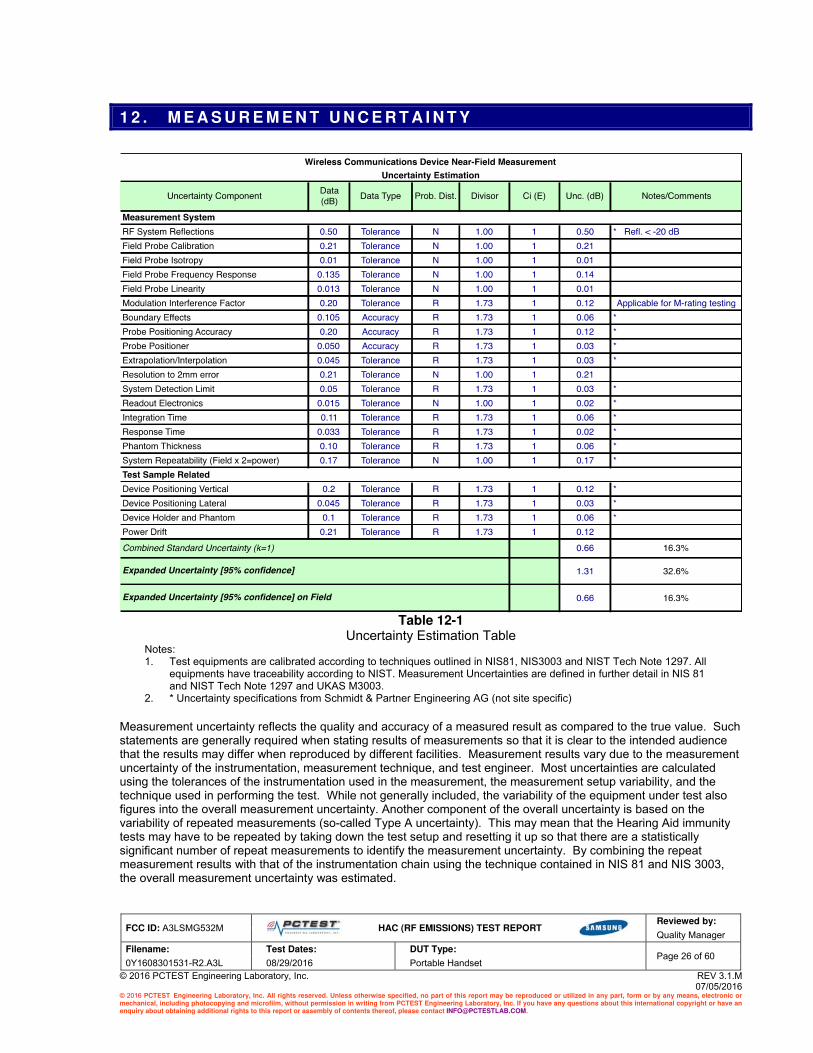
1 2 . M E A S U R E M E N T U N C E R T A I N T Y
Table 12-1
Uncertainty Estimation Table Notes: 1. Test equipments are calibrated according to techniques outlined in NIS81, NIS3003 and NIST Tech Note 1297. All
equipments have traceability according to NIST. Measurement Uncertainties are defined in further detail in NIS 81 and NIST Tech Note 1297 and UKAS M3003.
2. * Uncertainty specifications from Schmidt & Partner Engineering AG (not site specific)
Measurement uncertainty reflects the quality and accuracy of a measured result as compared to the true value. Such statements are generally required when stating results of measurements so that it is clear to the intended audience that the results may differ when reproduced by different facilities. Measurement results vary due to the measurement uncertainty of the instrumentation, measurement technique, and test engineer. Most uncertainties are calculated using the tolerances of the instrumentation used in the measurement, the measurement setup variability, and the technique used in performing the test. While not generally included, the variability of the equipment under test also figures into the overall measurement uncertainty. Another component of the overall uncertainty is based on the variability of repeated measurements (so-called Type A uncertainty). This may mean that the Hearing Aid immunity tests may have to be repeated by taking down the test setup and resetting it up so that there are a statistically significant number of repeat measurements to identify the measurement uncertainty. By combining the repeat measurement results with that of the instrumentation chain using the technique contained in NIS 81 and NIS 3003, the overall measurement uncertainty was estimated.

FCC ID: A3LSMG532M
HAC (RF EMISSIONS) TEST REPORT
Reviewed by:
Quality Manager
Filename: Test Dates: DUT Type: Page 27 of 60
0Y1608301531-R2.A3L 08/29/2016 Portable Handset
© 2016 PCTEST Engineering Laboratory, Inc. REV 3.1.M 07/05/2016
© 2016 PCTEST Engineering Laboratory, Inc. All rights reserved. Unless otherwise specified, no part of this report may be reproduced or utilized in any part, form or by any means, electronic or mechanical, including photocopying and microfilm, without permission in writing from PCTEST Engineering Laboratory, Inc. If you have any questions about this international copyright or have an enquiry about obtaining additional rights to this report or assembly of contents thereof, please contact [email protected].
1 3 . T E S T D A T A
See following Attached Pages for Test Data.

FCC ID: A3LSMG532M
HAC (RF EMISSIONS) TEST REPORT
Reviewed by:
Quality Manager
Filename: Test Dates: DUT Type: Page 28 of 60
0Y1608301531-R2.A3L 08/29/2016 Portable Handset
© 2016 PCTEST Engineering Laboratory, Inc. REV 3.1.M 07/05/2016
© 2016 PCTEST Engineering Laboratory, Inc. All rights reserved. Unless otherwise specified, no part of this report may be reproduced or utilized in any part, form or by any means, electronic or mechanical, including photocopying and microfilm, without permission in writing from PCTEST Engineering Laboratory, Inc. If you have any questions about this international copyright or have an enquiry about obtaining additional rights to this report or assembly of contents thereof, please contact [email protected].

FCC ID: A3LSMG532M
HAC (RF EMISSIONS) TEST REPORT
Reviewed by:
Quality Manager
Filename: Test Dates: DUT Type: Page 29 of 60
0Y1608301531-R2.A3L 08/29/2016 Portable Handset
© 2016 PCTEST Engineering Laboratory, Inc. REV 3.1.M 07/05/2016
© 2016 PCTEST Engineering Laboratory, Inc. All rights reserved. Unless otherwise specified, no part of this report may be reproduced or utilized in any part, form or by any means, electronic or mechanical, including photocopying and microfilm, without permission in writing from PCTEST Engineering Laboratory, Inc. If you have any questions about this international copyright or have an enquiry about obtaining additional rights to this report or assembly of contents thereof, please contact [email protected].

FCC ID: A3LSMG532M
HAC (RF EMISSIONS) TEST REPORT
Reviewed by:
Quality Manager
Filename: Test Dates: DUT Type: Page 30 of 60
0Y1608301531-R2.A3L 08/29/2016 Portable Handset
© 2016 PCTEST Engineering Laboratory, Inc. REV 3.1.M 07/05/2016
© 2016 PCTEST Engineering Laboratory, Inc. All rights reserved. Unless otherwise specified, no part of this report may be reproduced or utilized in any part, form or by any means, electronic or mechanical, including photocopying and microfilm, without permission in writing from PCTEST Engineering Laboratory, Inc. If you have any questions about this international copyright or have an enquiry about obtaining additional rights to this report or assembly of contents thereof, please contact [email protected].

FCC ID: A3LSMG532M
HAC (RF EMISSIONS) TEST REPORT
Reviewed by:
Quality Manager
Filename: Test Dates: DUT Type: Page 31 of 60
0Y1608301531-R2.A3L 08/29/2016 Portable Handset
© 2016 PCTEST Engineering Laboratory, Inc. REV 3.1.M 07/05/2016
© 2016 PCTEST Engineering Laboratory, Inc. All rights reserved. Unless otherwise specified, no part of this report may be reproduced or utilized in any part, form or by any means, electronic or mechanical, including photocopying and microfilm, without permission in writing from PCTEST Engineering Laboratory, Inc. If you have any questions about this international copyright or have an enquiry about obtaining additional rights to this report or assembly of contents thereof, please contact [email protected].

FCC ID: A3LSMG532M
HAC (RF EMISSIONS) TEST REPORT
Reviewed by:
Quality Manager
Filename: Test Dates: DUT Type: Page 32 of 60
0Y1608301531-R2.A3L 08/29/2016 Portable Handset
© 2016 PCTEST Engineering Laboratory, Inc. REV 3.1.M 07/05/2016
© 2016 PCTEST Engineering Laboratory, Inc. All rights reserved. Unless otherwise specified, no part of this report may be reproduced or utilized in any part, form or by any means, electronic or mechanical, including photocopying and microfilm, without permission in writing from PCTEST Engineering Laboratory, Inc. If you have any questions about this international copyright or have an enquiry about obtaining additional rights to this report or assembly of contents thereof, please contact [email protected].
1 4 . C A L I B R A T I O N C E R T I F I C A T E S
The following pages include the probe calibration used to evaluate HAC for the DUT.

FCC ID: A3LSMG532M
HAC (RF EMISSIONS) TEST REPORT
Reviewed by:
Quality Manager
Filename: Test Dates: DUT Type: Page 33 of 60
0Y1608301531-R2.A3L 08/29/2016 Portable Handset
© 2016 PCTEST Engineering Laboratory, Inc. REV 3.1.M 07/05/2016
© 2016 PCTEST Engineering Laboratory, Inc. All rights reserved. Unless otherwise specified, no part of this report may be reproduced or utilized in any part, form or by any means, electronic or mechanical, including photocopying and microfilm, without permission in writing from PCTEST Engineering Laboratory, Inc. If you have any questions about this international copyright or have an enquiry about obtaining additional rights to this report or assembly of contents thereof, please contact [email protected].

FCC ID: A3LSMG532M
HAC (RF EMISSIONS) TEST REPORT
Reviewed by:
Quality Manager
Filename: Test Dates: DUT Type: Page 34 of 60
0Y1608301531-R2.A3L 08/29/2016 Portable Handset
© 2016 PCTEST Engineering Laboratory, Inc. REV 3.1.M 07/05/2016
© 2016 PCTEST Engineering Laboratory, Inc. All rights reserved. Unless otherwise specified, no part of this report may be reproduced or utilized in any part, form or by any means, electronic or mechanical, including photocopying and microfilm, without permission in writing from PCTEST Engineering Laboratory, Inc. If you have any questions about this international copyright or have an enquiry about obtaining additional rights to this report or assembly of contents thereof, please contact [email protected].

FCC ID: A3LSMG532M
HAC (RF EMISSIONS) TEST REPORT
Reviewed by:
Quality Manager
Filename: Test Dates: DUT Type: Page 35 of 60
0Y1608301531-R2.A3L 08/29/2016 Portable Handset
© 2016 PCTEST Engineering Laboratory, Inc. REV 3.1.M 07/05/2016
© 2016 PCTEST Engineering Laboratory, Inc. All rights reserved. Unless otherwise specified, no part of this report may be reproduced or utilized in any part, form or by any means, electronic or mechanical, including photocopying and microfilm, without permission in writing from PCTEST Engineering Laboratory, Inc. If you have any questions about this international copyright or have an enquiry about obtaining additional rights to this report or assembly of contents thereof, please contact [email protected].

FCC ID: A3LSMG532M
HAC (RF EMISSIONS) TEST REPORT
Reviewed by:
Quality Manager
Filename: Test Dates: DUT Type: Page 36 of 60
0Y1608301531-R2.A3L 08/29/2016 Portable Handset
© 2016 PCTEST Engineering Laboratory, Inc. REV 3.1.M 07/05/2016
© 2016 PCTEST Engineering Laboratory, Inc. All rights reserved. Unless otherwise specified, no part of this report may be reproduced or utilized in any part, form or by any means, electronic or mechanical, including photocopying and microfilm, without permission in writing from PCTEST Engineering Laboratory, Inc. If you have any questions about this international copyright or have an enquiry about obtaining additional rights to this report or assembly of contents thereof, please contact [email protected].

FCC ID: A3LSMG532M
HAC (RF EMISSIONS) TEST REPORT
Reviewed by:
Quality Manager
Filename: Test Dates: DUT Type: Page 37 of 60
0Y1608301531-R2.A3L 08/29/2016 Portable Handset
© 2016 PCTEST Engineering Laboratory, Inc. REV 3.1.M 07/05/2016
© 2016 PCTEST Engineering Laboratory, Inc. All rights reserved. Unless otherwise specified, no part of this report may be reproduced or utilized in any part, form or by any means, electronic or mechanical, including photocopying and microfilm, without permission in writing from PCTEST Engineering Laboratory, Inc. If you have any questions about this international copyright or have an enquiry about obtaining additional rights to this report or assembly of contents thereof, please contact [email protected].
FCC ID: A3LSMG532M
HAC (RF EMISSIONS) TEST REPORT
Reviewed by:
Quality Manager
Filename: Test Dates: DUT Type: Page 38 of 60
0Y1608301531-R2.A3L 08/29/2016 Portable Handset
© 2016 PCTEST Engineering Laboratory, Inc. REV 3.1.M 07/05/2016
© 2016 PCTEST Engineering Laboratory, Inc. All rights reserved. Unless otherwise specified, no part of this report may be reproduced or utilized in any part, form or by any means, electronic or mechanical, including photocopying and microfilm, without permission in writing from PCTEST Engineering Laboratory, Inc. If you have any questions about this international copyright or have an enquiry about obtaining additional rights to this report or assembly of contents thereof, please contact [email protected].

FCC ID: A3LSMG532M
HAC (RF EMISSIONS) TEST REPORT
Reviewed by:
Quality Manager
Filename: Test Dates: DUT Type: Page 39 of 60
0Y1608301531-R2.A3L 08/29/2016 Portable Handset
© 2016 PCTEST Engineering Laboratory, Inc. REV 3.1.M 07/05/2016
© 2016 PCTEST Engineering Laboratory, Inc. All rights reserved. Unless otherwise specified, no part of this report may be reproduced or utilized in any part, form or by any means, electronic or mechanical, including photocopying and microfilm, without permission in writing from PCTEST Engineering Laboratory, Inc. If you have any questions about this international copyright or have an enquiry about obtaining additional rights to this report or assembly of contents thereof, please contact [email protected].

FCC ID: A3LSMG532M
HAC (RF EMISSIONS) TEST REPORT
Reviewed by:
Quality Manager
Filename: Test Dates: DUT Type: Page 40 of 60
0Y1608301531-R2.A3L 08/29/2016 Portable Handset
© 2016 PCTEST Engineering Laboratory, Inc. REV 3.1.M 07/05/2016
© 2016 PCTEST Engineering Laboratory, Inc. All rights reserved. Unless otherwise specified, no part of this report may be reproduced or utilized in any part, form or by any means, electronic or mechanical, including photocopying and microfilm, without permission in writing from PCTEST Engineering Laboratory, Inc. If you have any questions about this international copyright or have an enquiry about obtaining additional rights to this report or assembly of contents thereof, please contact [email protected].

FCC ID: A3LSMG532M
HAC (RF EMISSIONS) TEST REPORT
Reviewed by:
Quality Manager
Filename: Test Dates: DUT Type: Page 41 of 60
0Y1608301531-R2.A3L 08/29/2016 Portable Handset
© 2016 PCTEST Engineering Laboratory, Inc. REV 3.1.M 07/05/2016
© 2016 PCTEST Engineering Laboratory, Inc. All rights reserved. Unless otherwise specified, no part of this report may be reproduced or utilized in any part, form or by any means, electronic or mechanical, including photocopying and microfilm, without permission in writing from PCTEST Engineering Laboratory, Inc. If you have any questions about this international copyright or have an enquiry about obtaining additional rights to this report or assembly of contents thereof, please contact [email protected].

FCC ID: A3LSMG532M
HAC (RF EMISSIONS) TEST REPORT
Reviewed by:
Quality Manager
Filename: Test Dates: DUT Type: Page 42 of 60
0Y1608301531-R2.A3L 08/29/2016 Portable Handset
© 2016 PCTEST Engineering Laboratory, Inc. REV 3.1.M 07/05/2016
© 2016 PCTEST Engineering Laboratory, Inc. All rights reserved. Unless otherwise specified, no part of this report may be reproduced or utilized in any part, form or by any means, electronic or mechanical, including photocopying and microfilm, without permission in writing from PCTEST Engineering Laboratory, Inc. If you have any questions about this international copyright or have an enquiry about obtaining additional rights to this report or assembly of contents thereof, please contact [email protected].

FCC ID: A3LSMG532M
HAC (RF EMISSIONS) TEST REPORT
Reviewed by:
Quality Manager
Filename: Test Dates: DUT Type: Page 43 of 60
0Y1608301531-R2.A3L 08/29/2016 Portable Handset
© 2016 PCTEST Engineering Laboratory, Inc. REV 3.1.M 07/05/2016
© 2016 PCTEST Engineering Laboratory, Inc. All rights reserved. Unless otherwise specified, no part of this report may be reproduced or utilized in any part, form or by any means, electronic or mechanical, including photocopying and microfilm, without permission in writing from PCTEST Engineering Laboratory, Inc. If you have any questions about this international copyright or have an enquiry about obtaining additional rights to this report or assembly of contents thereof, please contact [email protected].

FCC ID: A3LSMG532M
HAC (RF EMISSIONS) TEST REPORT
Reviewed by:
Quality Manager
Filename: Test Dates: DUT Type: Page 44 of 60
0Y1608301531-R2.A3L 08/29/2016 Portable Handset
© 2016 PCTEST Engineering Laboratory, Inc. REV 3.1.M 07/05/2016
© 2016 PCTEST Engineering Laboratory, Inc. All rights reserved. Unless otherwise specified, no part of this report may be reproduced or utilized in any part, form or by any means, electronic or mechanical, including photocopying and microfilm, without permission in writing from PCTEST Engineering Laboratory, Inc. If you have any questions about this international copyright or have an enquiry about obtaining additional rights to this report or assembly of contents thereof, please contact [email protected].
FCC ID: A3LSMG532M
HAC (RF EMISSIONS) TEST REPORT
Reviewed by:
Quality Manager
Filename: Test Dates: DUT Type: Page 45 of 60
0Y1608301531-R2.A3L 08/29/2016 Portable Handset
© 2016 PCTEST Engineering Laboratory, Inc. REV 3.1.M 07/05/2016
© 2016 PCTEST Engineering Laboratory, Inc. All rights reserved. Unless otherwise specified, no part of this report may be reproduced or utilized in any part, form or by any means, electronic or mechanical, including photocopying and microfilm, without permission in writing from PCTEST Engineering Laboratory, Inc. If you have any questions about this international copyright or have an enquiry about obtaining additional rights to this report or assembly of contents thereof, please contact [email protected].
FCC ID: A3LSMG532M
HAC (RF EMISSIONS) TEST REPORT
Reviewed by:
Quality Manager
Filename: Test Dates: DUT Type: Page 46 of 60
0Y1608301531-R2.A3L 08/29/2016 Portable Handset
© 2016 PCTEST Engineering Laboratory, Inc. REV 3.1.M 07/05/2016
© 2016 PCTEST Engineering Laboratory, Inc. All rights reserved. Unless otherwise specified, no part of this report may be reproduced or utilized in any part, form or by any means, electronic or mechanical, including photocopying and microfilm, without permission in writing from PCTEST Engineering Laboratory, Inc. If you have any questions about this international copyright or have an enquiry about obtaining additional rights to this report or assembly of contents thereof, please contact [email protected].
FCC ID: A3LSMG532M
HAC (RF EMISSIONS) TEST REPORT
Reviewed by:
Quality Manager
Filename: Test Dates: DUT Type: Page 47 of 60
0Y1608301531-R2.A3L 08/29/2016 Portable Handset
© 2016 PCTEST Engineering Laboratory, Inc. REV 3.1.M 07/05/2016
© 2016 PCTEST Engineering Laboratory, Inc. All rights reserved. Unless otherwise specified, no part of this report may be reproduced or utilized in any part, form or by any means, electronic or mechanical, including photocopying and microfilm, without permission in writing from PCTEST Engineering Laboratory, Inc. If you have any questions about this international copyright or have an enquiry about obtaining additional rights to this report or assembly of contents thereof, please contact [email protected].

FCC ID: A3LSMG532M
HAC (RF EMISSIONS) TEST REPORT
Reviewed by:
Quality Manager
Filename: Test Dates: DUT Type: Page 48 of 60
0Y1608301531-R2.A3L 08/29/2016 Portable Handset
© 2016 PCTEST Engineering Laboratory, Inc. REV 3.1.M 07/05/2016
© 2016 PCTEST Engineering Laboratory, Inc. All rights reserved. Unless otherwise specified, no part of this report may be reproduced or utilized in any part, form or by any means, electronic or mechanical, including photocopying and microfilm, without permission in writing from PCTEST Engineering Laboratory, Inc. If you have any questions about this international copyright or have an enquiry about obtaining additional rights to this report or assembly of contents thereof, please contact [email protected].
FCC ID: A3LSMG532M
HAC (RF EMISSIONS) TEST REPORT
Reviewed by:
Quality Manager
Filename: Test Dates: DUT Type: Page 49 of 60
0Y1608301531-R2.A3L 08/29/2016 Portable Handset
© 2016 PCTEST Engineering Laboratory, Inc. REV 3.1.M 07/05/2016
© 2016 PCTEST Engineering Laboratory, Inc. All rights reserved. Unless otherwise specified, no part of this report may be reproduced or utilized in any part, form or by any means, electronic or mechanical, including photocopying and microfilm, without permission in writing from PCTEST Engineering Laboratory, Inc. If you have any questions about this international copyright or have an enquiry about obtaining additional rights to this report or assembly of contents thereof, please contact [email protected].
FCC ID: A3LSMG532M
HAC (RF EMISSIONS) TEST REPORT
Reviewed by:
Quality Manager
Filename: Test Dates: DUT Type: Page 50 of 60
0Y1608301531-R2.A3L 08/29/2016 Portable Handset
© 2016 PCTEST Engineering Laboratory, Inc. REV 3.1.M 07/05/2016
© 2016 PCTEST Engineering Laboratory, Inc. All rights reserved. Unless otherwise specified, no part of this report may be reproduced or utilized in any part, form or by any means, electronic or mechanical, including photocopying and microfilm, without permission in writing from PCTEST Engineering Laboratory, Inc. If you have any questions about this international copyright or have an enquiry about obtaining additional rights to this report or assembly of contents thereof, please contact [email protected].

FCC ID: A3LSMG532M
HAC (RF EMISSIONS) TEST REPORT
Reviewed by:
Quality Manager
Filename: Test Dates: DUT Type: Page 51 of 60
0Y1608301531-R2.A3L 08/29/2016 Portable Handset
© 2016 PCTEST Engineering Laboratory, Inc. REV 3.1.M 07/05/2016
© 2016 PCTEST Engineering Laboratory, Inc. All rights reserved. Unless otherwise specified, no part of this report may be reproduced or utilized in any part, form or by any means, electronic or mechanical, including photocopying and microfilm, without permission in writing from PCTEST Engineering Laboratory, Inc. If you have any questions about this international copyright or have an enquiry about obtaining additional rights to this report or assembly of contents thereof, please contact [email protected].

FCC ID: A3LSMG532M
HAC (RF EMISSIONS) TEST REPORT
Reviewed by:
Quality Manager
Filename: Test Dates: DUT Type: Page 52 of 60
0Y1608301531-R2.A3L 08/29/2016 Portable Handset
© 2016 PCTEST Engineering Laboratory, Inc. REV 3.1.M 07/05/2016
© 2016 PCTEST Engineering Laboratory, Inc. All rights reserved. Unless otherwise specified, no part of this report may be reproduced or utilized in any part, form or by any means, electronic or mechanical, including photocopying and microfilm, without permission in writing from PCTEST Engineering Laboratory, Inc. If you have any questions about this international copyright or have an enquiry about obtaining additional rights to this report or assembly of contents thereof, please contact [email protected].

FCC ID: A3LSMG532M
HAC (RF EMISSIONS) TEST REPORT
Reviewed by:
Quality Manager
Filename: Test Dates: DUT Type: Page 53 of 60
0Y1608301531-R2.A3L 08/29/2016 Portable Handset
© 2016 PCTEST Engineering Laboratory, Inc. REV 3.1.M 07/05/2016
© 2016 PCTEST Engineering Laboratory, Inc. All rights reserved. Unless otherwise specified, no part of this report may be reproduced or utilized in any part, form or by any means, electronic or mechanical, including photocopying and microfilm, without permission in writing from PCTEST Engineering Laboratory, Inc. If you have any questions about this international copyright or have an enquiry about obtaining additional rights to this report or assembly of contents thereof, please contact [email protected].
FCC ID: A3LSMG532M
HAC (RF EMISSIONS) TEST REPORT
Reviewed by:
Quality Manager
Filename: Test Dates: DUT Type: Page 54 of 60
0Y1608301531-R2.A3L 08/29/2016 Portable Handset
© 2016 PCTEST Engineering Laboratory, Inc. REV 3.1.M 07/05/2016
© 2016 PCTEST Engineering Laboratory, Inc. All rights reserved. Unless otherwise specified, no part of this report may be reproduced or utilized in any part, form or by any means, electronic or mechanical, including photocopying and microfilm, without permission in writing from PCTEST Engineering Laboratory, Inc. If you have any questions about this international copyright or have an enquiry about obtaining additional rights to this report or assembly of contents thereof, please contact [email protected].

FCC ID: A3LSMG532M
HAC (RF EMISSIONS) TEST REPORT
Reviewed by:
Quality Manager
Filename: Test Dates: DUT Type: Page 55 of 60
0Y1608301531-R2.A3L 08/29/2016 Portable Handset
© 2016 PCTEST Engineering Laboratory, Inc. REV 3.1.M 07/05/2016
© 2016 PCTEST Engineering Laboratory, Inc. All rights reserved. Unless otherwise specified, no part of this report may be reproduced or utilized in any part, form or by any means, electronic or mechanical, including photocopying and microfilm, without permission in writing from PCTEST Engineering Laboratory, Inc. If you have any questions about this international copyright or have an enquiry about obtaining additional rights to this report or assembly of contents thereof, please contact [email protected].
1 5 . C O N C L U S I O N
The measurements indicate that the wireless communications device complies with the HAC limits specified in accordance with the ANSI C63.19 Standard and FCC WT Docket No. 01-309 RM-8658. Precise laboratory measures were taken to assure repeatability of the tests. The tested device complies with the requirements in respect to all parameters specific to the test. The test results and statements relate only to the item(s) tested. Please note that the M-rating for this equipment only represents the field interference possible against a hypothetical and typical hearing aid. The measurement system and techniques presented in this evaluation are proposed in the ANSI standard as a means of best approximating wireless device compatibility with a hearing-aid. The literature is under continual re-construction.

FCC ID: A3LSMG532M
HAC (RF EMISSIONS) TEST REPORT
Reviewed by:
Quality Manager
Filename: Test Dates: DUT Type: Page 56 of 60
0Y1608301531-R2.A3L 08/29/2016 Portable Handset
© 2016 PCTEST Engineering Laboratory, Inc. REV 3.1.M 07/05/2016
© 2016 PCTEST Engineering Laboratory, Inc. All rights reserved. Unless otherwise specified, no part of this report may be reproduced or utilized in any part, form or by any means, electronic or mechanical, including photocopying and microfilm, without permission in writing from PCTEST Engineering Laboratory, Inc. If you have any questions about this international copyright or have an enquiry about obtaining additional rights to this report or assembly of contents thereof, please contact [email protected].
1 6 . R E F E R E N C E S
1. ANSI/IEEE C63.19-2011, “American National Standard for Methods of Measurement of
Compatibility between Wireless Communication Devices and Hearing Aids.”, New York, NY, IEEE, May 2011
2. FCC Office of Engineering and Technology KDB, “285076 D01 HAC Guidance v04,” October 31,
2013
3. FCC Office of Engineering and Technology KDB, “285076 D02 T-Coil Testing for CMRS IP v01r01,” October 31, 2013
4. FCC Public Notice DA 06-1215, Wireless Telecommunications Bureau and Office of Engineering
and Technology Clarify Use of Revised Wireless Phone Hearing Aid Compatibility Standard, June 6, 2006
5. FCC 3G Review Guidance, Laboratory Division OET FCC, May/June 2006 6. Berger, H. S., “Compatibility Between Hearing Aids and Wireless Devices,” Electronic Industries
Forum, Boston, MA, May, 1997 7. Berger, H. S., “Hearing Aid and Cellular Phone Compatibility: Working Toward Solutions,”
Wireless Telephones and Hearing Aids: New Challenges for Audiology, Gallaudet University, Washington, D.C., May, 1997 (To be reprinted in the American Journal of Audiology).
8. Berger, H. S., “Hearing Aid Compatibility with Wireless Communications Devices, “ IEEE
International Symposium on Electromagnetic Compatibility, Austin, TX, August, 1997.
9. Bronaugh, E. L., “Simplifying EMI Immunity (Susceptibility) Tests in TEM Cells,” in the 1990 IEEE International Symposium on Electromagnetic Compatibility Symposium Record, Washington, D.C., August 1990, pp. 488-491
10. Byme, D. and Dillon, H., The National Acoustics Laboratory (NAL) New Procedure for Selecting
the Gain and Frequency Response of a Hearing Aid, Ear and Hearing 7:257-265, 1986.
11. Crawford, M. L., “Measurement of Electromagnetic Radiation from Electronic Equipment using TEM Transmission Cells, “ U.S. Department of Commerce, National Bureau of Standards, NBSIR 73-306, Feb. 1973.
12. Crawford, M. L., and Workman, J. L., “Using a TEM Cell for EMC Measurements of Electronic
Equipment,” U.S. Department of Commerce, National Bureau of Standards. Technical Note 1013, July 1981.
13. Decker, W. F., Crawford, M. L., and Wilson, W. A., “Construction of a Large Transverse Electromagnetic Cell”, U.S. Department of Commerce, National Bureau of Standards, Technical Note 1011, Feb. 1979.
14. EHIMA GSM Project, Development phase, Project Report (1
st part) Revision A. Technical-
Audiological Laboratory and Telecom Denmark, October 1993.

FCC ID: A3LSMG532M
HAC (RF EMISSIONS) TEST REPORT
Reviewed by:
Quality Manager
Filename: Test Dates: DUT Type: Page 57 of 60
0Y1608301531-R2.A3L 08/29/2016 Portable Handset
© 2016 PCTEST Engineering Laboratory, Inc. REV 3.1.M 07/05/2016
© 2016 PCTEST Engineering Laboratory, Inc. All rights reserved. Unless otherwise specified, no part of this report may be reproduced or utilized in any part, form or by any means, electronic or mechanical, including photocopying and microfilm, without permission in writing from PCTEST Engineering Laboratory, Inc. If you have any questions about this international copyright or have an enquiry about obtaining additional rights to this report or assembly of contents thereof, please contact [email protected].
15. EHIMA GSM Project, Development phase, Part II Project Report. Technical-Audiological Laboratory and Telecom Denmark, June 1994.
16. EHIMA GSM Project Final Report, Hearing Aids and GSM Mobile Telephones: Interference
Problems, Methods of Measurement and Levels of Immunity. Technical-Audiological Laboratory and Telecom Denmark, 1995.
17. HAMPIS Report, Comparison of Mobile phone electromagnetic near field with an upscaled
electromagnetic far field, using hearing aid as reference, 21 October 1999.
18. Hearing Aids/GSM, Report from OTWIDAM, Technical-Audiological Laboratory and Telecom Denmark, April 1993.
19. IEEE 100, The Authoritative Dictionary of IEEE Standards Terms, Seventh Edition.
20. Joyner, K. H, et. al., Interference to Hearing Aids by the New Digital Mobile Telephone System,
Global System for Mobile (GSM) Communication Standard, National Acoustic Laboratory, Australian Hearing Series, Sydney 1993.
21. Joyner, K. H., et. al., Interference to Hearing Aids by the Digital Mobile Telephone System, Global
System for Mobile Communications (GSM), NAL Report #131, National Acoustic Laboratory, Australian Hearing Series, Sydney, 1995.
22. Konigstein, D., and Hansen, D., “A New Family of TEM Cells with enlarged bandwidth and
Optimized working Volume,” in the Proceedings of the 7th International Symposium on EMC,
Zurich, Switzerland, March 1987; 50:9, pp. 127-132.
23. Kuk, F., and Hjorstgaard, N. K., “Factors affecting interference from digital cellular telephones,” Hearing Journal, 1997; 50:9, pp 32-34.
24. Ma, M. A., and Kanda, M., ”Electromagnetic Compatibility and Interference Metrology,” U.S.
Department of Commerce, National Bureau of Standards, Technical Note 1099, July 1986, pp. 17-43.
25. Ma, M. A., Sreenivashiah, I. , and Chang, D. C., “A Method of Determining the Emission and
Susceptibility Levels of Electrically Small Objects Using a TEM Cell,” U.S. Department of Commerce, National Bureau of Standards, Technial Note 1040, July 1981.
26. McCandless, G. A., and Lyregaard, P. E., Prescription of Gain/Output (POGO) for Hearing Aids,
Hearing Instruments 1:16-21, 1983
27. Skopec, M., “Hearing Aid Electromagnetic Interference from Digital Wireless Telephones, “IEEE Transactions on Rehabilitation Engineering, vol. 6, no. 2, pp. 235-239, June 1998.
28. Technical Report, GSM 05.90, GSM EMC Considerations, European Telecommunications
Standards Institute, January 1993.
29. Victorian, T. A., “Digital Cellular Telephone Interference and Hearing Aid Compatibility—an Update,” Hearing Journal 1998; 51:10, pp. 53-60
30. Wong, G. S. K., and Embleton, T. F. W., eds., AIP Handbook of Condenser Microphones: Theory,
Calibration and Measurements, AIP Press.