Embed Size (px)
Citation preview
Important InformationContents
Introduction 1
Principles 2Synchronization of PCS7Systems (System Bus) 3Synchronization of PCS7Systems (Terminal Bus) 4
Daylight saving time /Wintertime
5
Annexes
SICLOCK / DCF77 / GPS A
s
PCS7 V5.x
Clock Synchronization
Configuration Guide
09/2002 issue
Siemens AG
PCS7 Clock Synchronization2
Contents
1 Introduction ................................................................................................................... 3
2 Principles....................................................................................................................... 42.1 The Settings in the HW Config .................................................................................................. 4
2.1.1 CPU Object Properties....................................................................................................... 42.1.2 CP443-1 Object Properties ................................................................................................ 5
2.2 The "Time Synchronization" Editor in the OS ......................................................................... 102.2.1 General Information about the "Time Synchronization" Editor: ....................................... 102.2.2 How the Time Synchronization Works: ............................................................................ 102.2.3 "Time Synchronization" Dialog Window........................................................................... 11
3 Synchronization of PCS7 Systems (System Bus)..................................................... 143.1 OS as a Time Master (Case A/B)............................................................................................ 15
3.1.1 OS with CP1613............................................................................................................... 153.1.2 OS with CP5412............................................................................................................... 223.1.3 OS mit CP5613 ................................................................................................................ 223.1.4 OS with a 3COM Network Card and BCE........................................................................ 233.1.5 DCF 77 Receiver for WinCC............................................................................................ 233.1.6 GPS Receiver for WinCC................................................................................................. 25
3.2 PLC as a Time Master (Case C ) ............................................................................................ 263.2.1 FAQ: Time Synchronization for PCS 7 V5.x via CP1413 ................................................ 26
3.3 SICLOCK as a Time Master (Case D) .................................................................................... 323.3.1 FAQ: Configuration of the SICLOCK TM with GPSDEC in PCS 7 V5.x .......................... 32
4 Synchronization of PCS7 Systems (Terminal Bus)................................................... 334.1 DCF77 Receive Utility ............................................................................................................. 33
4.1.1 FAQ: Time Synchronization for OS Clients...................................................................... 33
5 Daylight saving time / Wintertime .............................................................................. 355.1 Automatic Adjustment ............................................................................................................. 35
5.1.1 FAQ: Messages in Runtime are Running One Hour Ahead ............................................ 365.2 Manual Adjustment.................................................................................................................. 37
5.2.1 FAQ: Problems Arising when Adjusting the System Time............................................... 375.3 Loading in Images ................................................................................................................... 38
5.3.1 FAQ: Daylight Saving Changes when Loading in Images ............................................... 38
Annex ................................................................................................................................. 39A SICLOCK / DCF77 /GPS ............................................................................................................ 39
Siemens AG
PCS7 Clock Synchronization3
1 Introduction
OS-Clients
OS-Server
SICLOCKPLC
terminal bus
system bus
external signal (DCF77 / GPS)
alternativelyOS-ServerSICLOCKorPLCastime master
Industrial Ethernet /Profibus
TCP/IP LAN
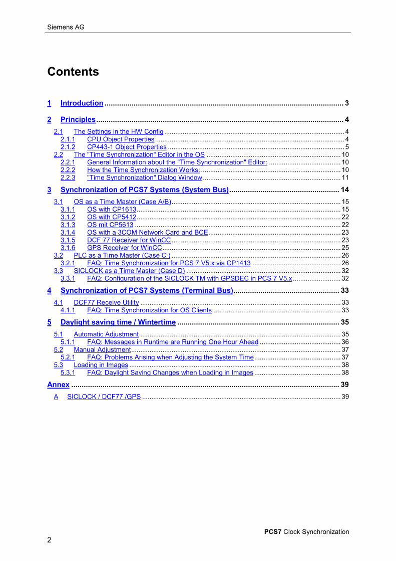
Time synchronization in PCS7 means that an active time master synchronizes all the OSs and PLCson the system bus at the current time.
In order to ensure the time consistency of the PCS 7 system, all the PLCs, OS servers and OS clientsmust be synchronized, thereby facilitating synchronized event signal processing (archiving, display,redundancy balance) system-wide, including on the terminal bus.
The function of the time master on the system bus can be performed by either an OS, a PLC or anexternal clock, such as SICLOCK TM.

Siemens AG
PCS7 Clock Synchronization4
2 PrinciplesThis section explains the possible time synchronization settings in the PCS7 components on the basisof the relevant help texts.The concepts and specific configuration guides which are suitable for PCS7 are presented in section3.
2.1 The Settings in the HW Config
2.1.1 CPU Object Properties
The Help function contains the following description:
Synchronization can be set separately:• in the PLC (i.e. internal)• on an MPI (i.e. external)
You can set the following parameters in the "Clock" box:
Type of SynchronizationYou can define whether the PLC module time synchronizes other clocks (possible settings are CPU-dependent).• As slave The PLC time is synchronized by another clock• As master The PLC time synchronizes other clocks as the master• None No synchronization takes place
Siemens AG
PCS7 Clock Synchronization5
Time IntervalSelect the time intervals within which synchronization is to take place.
Correction FactorThe correction factor is used to compensate for a deviation in the PLC time within a 24 hour period.You can enter positive or negative values in ms.For example, if the PLC time loses 4 seconds after 24 hours, you need to enter a correction factor of"+4000 ms".--------------------
Note:You can also set the PLC time• online using STEP 7 (with the menu command Target System > Set Time, for example)• in your user program via SFC 0 SET_CLK
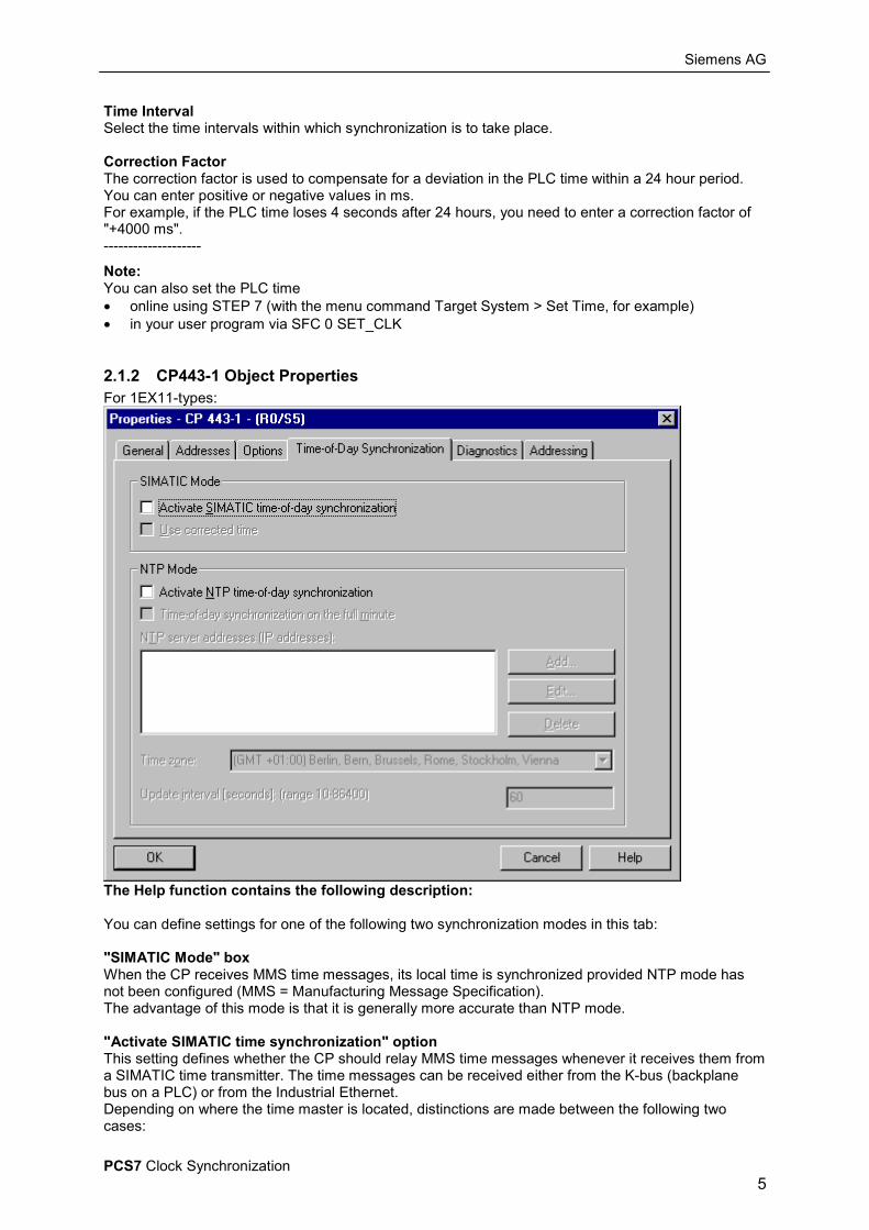
2.1.2 CP443-1 Object PropertiesFor 1EX11-types:
The Help function contains the following description:
You can define settings for one of the following two synchronization modes in this tab:
"SIMATIC Mode" boxWhen the CP receives MMS time messages, its local time is synchronized provided NTP mode hasnot been configured (MMS = Manufacturing Message Specification).The advantage of this mode is that it is generally more accurate than NTP mode.
"Activate SIMATIC time synchronization" optionThis setting defines whether the CP should relay MMS time messages whenever it receives them froma SIMATIC time transmitter. The time messages can be received either from the K-bus (backplanebus on a PLC) or from the Industrial Ethernet.Depending on where the time master is located, distinctions are made between the following twocases:
Siemens AG
PCS7 Clock Synchronization6
• Time messages may be received from the subnet (system bus) and be relayed to the station. Forthis purpose the CPU's time synchronization must be configured as a slave.
• Time messages may be received from the station and be relayed to the subnet (system bus). Forthis purpose the CPU's time synchronization must be configured as a master, or another CP mustrelay time messages on the K-bus.
If you operate a number of CPs within your station, you ought to give some attention to the flow of timemessages depending on the time master because you can link time messages from one network intoanother using the function described here. Your station may only have one time master.If a station has more than one CP to be connected to the same network, the time messages may onlybe relayed by one of these CPs.
"Use corrected time" optionThe "Use corrected time" option allows you to decide whether attention needs to be given to acorrection factor which may be transmitted in the time message. The correction factor defines a zerooffset (in units of ½ an hour) which comes about by defining the time zone setting or thesummer/winter time setting for the time transmitter.If you enable this option, the CP incorporates the correction factor into the time so that downstreamsystems do not have to take this factor into account.For example, 9:21 is transmitted as the time in the time message. The time message also contains thecorrection factor +2x0.5. Consequently, the corrected time relayed is 10:21.
"NTP Mode" boxIn NTP mode, the CP transmits time queries (in client mode) to the NTP server in the subnet (systembus) at regular intervals. Taking the responses from the servers as a basis, the most reliable and mostprecise time is ascertained, and the time of the station is synchronized.The advantage of this mode is that it enables the time to be synchronized over and beyond subnetlimits.
"Activate NTP time synchronization" optionThis setting defines whether the CP should synchronize the time in NTP mode. In this case any MMStime messages received are ignored.The IP addresses of up to four NTP servers are to be configured. The updating interval dictates thelength of time that elapses (in seconds) between time queries. The possible values for the intervalrange from 10 seconds to one day.Transmissions in NTP mode are generally UTC (Universal Time Coordinated); this corresponds toGMT (Greenwich Mean Time). The time offset can be set against the UTC through the configuration ofthe local time zone.
"Time synchronization on the full minute" optionThe "Time synchronization on the full minute” option can be used to decide whether the time is to berelayed on the K-bus precisely on the full minute.This option is only necessary for some special applications.
Siemens AG
PCS7 Clock Synchronization7
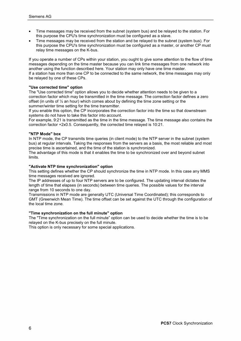
2.1.2.1 FAQ: Time Relay of the Industrial Ethernet CPsEntry ID 2330917Date 05.06.2000
QUESTION:Under which circumstances does an Industrial Ethernet CP forward time-of-day frames and in whichdirection are they forwarded?
ANSWER:If appropriately programmed, an Industrial Ethernet CP forwards time-of-day frames in the followingdirections:
• vom K-Bus in Richtung AnlagenbusWenn die zugehörige CPU ein Uhrzeitmaster ist und Uhrzeittelegramme absendet, werdendiese Telegramme vom CP auf das Anlagenbus gesendet.
• vom Anlagenbus in Richtung K-BusWenn sich auf dem Anlagenbus Uhrzeittelegramme befinden, dann werden dieseTelegramme vom CP auf den K-Bus weitergeleitet.
The requirement for this is that you must have activated the "Activate time-of-day synchronization"in the "Properties" dialog of the CP. The configuration mask is shown below and can be called in thehardware configuration or in NETPRO:
Note:The "Use corrected time" option refers to the format of the time-of-day frames with regard to daylightsaving time and winter time. Furthermore, this option refers only to forwarding from the LAN to theCommunication bus. If you use a SINEC time-of-day transmitter, the daylight saving time is output aswinter time + 2 x 1/2 hour (coded in the frame).
Siemens AG
PCS7 Clock Synchronization8
If the option is activated, then the CP adds an hour to the winter time and transmits the correct time-of-day frame to the Communication bus. If the option is not activated, then the time-of-day frame isforwarded without any editing.
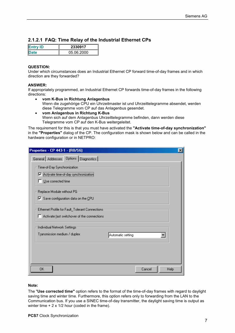
The following system configuration is given to demonstrate:
Two SIMATIC S7-400 stations have an Industrial Ethernet CP 443-1 each. The CPs are connected tothe subnetwork "Ethernet(2)" and can communicate directly with each other. The CPU 417-4 in thestation "AS400_IE1_Router_N1_N2" is configured as a clock master and transmits time-of-day framescyclically to the Communication bus. These frames are transmitted by the CP of this station to theLAN.
The time-of-day frames are forwarded by the CP 443-1 of the station "AS400_IE2_Router_N2_N3"from the LAN to the Communication bus. The CPU in the station IE2 is configured as a clock slaveand is synchronized cyclically by the time-of-day frames received.
Assumption:There is another clock master on the subnetwork "Ethernet(2)". This also sends time-of-day framescyclically to the LAN, which can be received by all CPs connected.
Problem:The CP 443-1 in the station "AS400_IE1_Router_N1_N2" now receives time-of-day frames both fromCPU and from the second clock master on the LAN. This ends in a collision of the time-of-day frames.

Siemens AG
PCS7 Clock Synchronization9
These "unexpected" events are entered in the diagnostics buffer of the CP:
The diagnostics buffer entries are to be interpreted as follows:• The entry "52" in the diagnostics buffer indicates that the CP is ready to forward time-of-day
frames. After this entry, the direction of time-of-day forwarding is determined by the nextincoming time-of-day frame. In this case this is a frame that has been received on thecommunication bus.
• The entry "53" indicates an unexpected frame from the LAN. This means that a time-of-dayframe has been received from the second clock master. Since it is unexpected, it is notforwarded. But the CP notices that a frame has been received from the LAN and would alsoforward the next time-of-day frame received from the LAN.
• Now, if a time-of-day frame arrives from the communication bus, entry "54" is generated. Thisframe is also not forwarded and leads to expiry of the watchdog timer after 200ms (entry"55").
• Now the initial status has been achieved and the next incoming time-of-day frame determinesthe direction of forwarding. Since both clock masters are still operating, this process repeatsitself cyclically.
Special point:The behavior described is only reproducible if the CPs are in "RUN". The situation changes if the CP isin "STOP". In the "STOP" state no productive communication is possible via a CP. The time-of-daytask does work however with limited scope of functions.In the "STOP" state of the CP, the time-of-day frames are forwarded only from the LAN to thecommunication bus. There is no forwarding in the reverse direction.This means that in our case the time-of-day frames of the second clock master on the LAN areforwarded by the CP in the station IE1 to the communication bus. The time-of-day frames of the CPUhowever are blocked and there are collisions of the time-of-day frames in the CP.
Siemens AG
PCS7 Clock Synchronization10
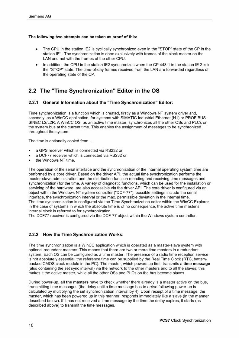
The following two attempts can be taken as proof of this:
• The CPU in the station IE2 is cyclically synchronized even in the "STOP" state of the CP in thestation IE1. The synchronization is done exclusively with frames of the clock master on theLAN and not with the frames of the other CPU.
• In addition, the CPU in the station IE2 synchronizes when the CP 443-1 in the station IE 2 is inthe "STOP" state. The time-of-day frames received from the LAN are forwarded regardless ofthe operating state of the CP.
2.2 The "Time Synchronization" Editor in the OS
2.2.1 General Information about the "Time Synchronization" Editor:
Time synchronization is a function which is created, firstly as a Windows NT system driver and,secondly, as a WinCC application, for systems with SIMATIC Industrial Ethernet (H1) or PROFIBUSSINEC L2/L2R. A WinCC OS, as an active time master, synchronizes all the other OSs and PLCs onthe system bus at the current time. This enables the assignment of messages to be synchronizedthroughout the system.
The time is optionally copied from ...
• a GPS receiver which is connected via RS232 or• a DCF77 receiver which is connected via RS232 or• the Windows NT time.
The operation of the serial interface and the synchronization of the internal operating system time areperformed by a core driver. Based on the driver API, the actual time synchronization performs themaster-slave administration and the distribution function (sending and receiving time messages andsynchronization) for the time. A variety of diagnostic functions, which can be used for the installation orservicing of the hardware, are also accessible via the driver API. The core driver is configured via anobject within the Windows NT system controller ("DCF-77"); possible settings include the serialinterface, the synchronization interval or the max. permissible deviation in the internal time.The time synchronization is configured via the Time Synchronization editor within the WinCC Explorer.In the case of systems in which the absolute time is of no consequence, the active time master'sinternal clock is referred to for synchronization.The DCF77 receiver is configured via the DCF-77 object within the Windows system controller.
2.2.2 How the Time Synchronization Works:
The time synchronization is a WinCC application which is operated as a master-slave system withoptional redundant masters. This means that there are two or more time masters in a redundantsystem. Each OS can be configured as a time master. The presence of a radio time reception serviceis not absolutely essential; the reference time can be supplied by the Real Time Clock (RTC, battery-backed CMOS clock module in the PC). The master, which powers up first, transmits a time message(also containing the set sync interval) via the network to the other masters and to all the slaves; thismakes it the active master, while all the other OSs and PLCs on the bus become slaves.
During power-up, all the masters have to check whether there already is a master active on the bus,transmitting time messages (the delay until a time message has to arrive following power-up iscalculated by multiplying the set synchronization interval by 4). Upon receipt of a time message, themaster, which has been powered up in this manner, responds immediately like a slave (in the mannerdescribed below). If it has not received a time message by the time the delay expires, it starts (asdescribed above) to transmit the time messages.

Siemens AG
PCS7 Clock Synchronization11
Redundant masters tell that they have become slaves by receiving the time message. Theysynchronize their clock to the time of day contained in the time message. They now use a timer (inaccordance with the sync interval contained in the time message) to check the cyclical receipt of timemessage from the active master. If three time messages fail to arrive in a row, the first redundantmaster that notices this starts to send time messages. This mechanism serves to ensure that timemessages are only ever transmitted by one master. Even if the DCF77 / GPS receiver is intact, theredundant masters only use the time message that they have received for checking the function of theactive master. They do not compare (check) the time of their own DCF77 / GPS receivers with thetime on the time messages that they have received. Consequently, all the redundant masters behavelike time slaves.
All time slaves and redundant masters on the system bus synchronize their internal clock with thereceipt of a time message.The setting of the time zone-dependent offset of the system time and the daylight saving change isperformed automatically by means of the time zone and daylight saving change set in Windows. Thismeans that the correct time is displayed and change is performed, even if time reception isinterrupted. When using a DCF77 receiver, a warning is entered in the event protocol whenever thesystem is powered up if there is a discrepancy in terms of the time zone and daylight saving change(CET/CEST). The GPS system supplies the UTC independent of time zone and ST/WT; consequently,the system time must be corrected by the driver by means of the time zone and daylight savingchange set in Windows.
If the time synchronization is realized via an Industrial Ethernet time transmitter (H1), the timetransmitter has to be set to the normal time for the local time zone. The change to summer time maynot be activated on the Industrial Ethernet time transmitter (H1). The OS receives the time messagevia the connected system bus on the PLC and performs the change between ST and WT in line withthe settings in the operating system.
In order to ensure that signals are processed properly (archiving, display, redundancy balance), thetimes on the OS servers and on the connected PLC components need to be synchronized.The synchronization interval may not be adjusted during runtime. Configuration must take place beforeruntime is activated.
2.2.3 "Time Synchronization" Dialog WindowThe time synchronization can be configured within the WinCC Explorer. Procedure for opening the requisite dialog:
1. In the project navigation window, click the right mouse button on the "Time Synchronization" editor.
2. A context-sensitive menu then appears; select the "Open" option.3. The "Time Synchronization" dialog window is opened, and you can define all the requisite settings.%_&_')(+*,&.-
The configuration of the time synchronization is computer-specific and has to be performed on everycomputer. If you are using Project Download or Project Duplicator, the settings are not copied over atthe same time.
Siemens AG
PCS7 Clock Synchronization12
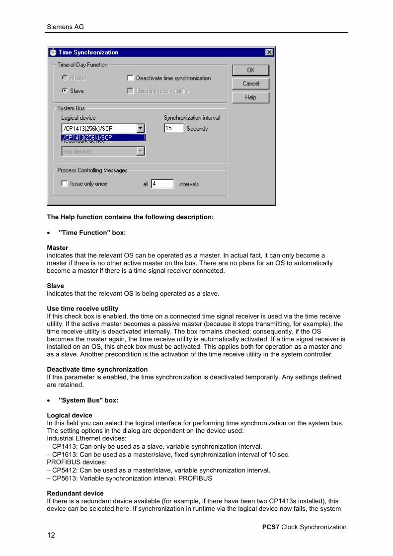
The Help function contains the following description:
• "Time Function" box:
Masterindicates that the relevant OS can be operated as a master. In actual fact, it can only become amaster if there is no other active master on the bus. There are no plans for an OS to automaticallybecome a master if there is a time signal receiver connected.
Slaveindicates that the relevant OS is being operated as a slave.
Use time receive utilityIf this check box is enabled, the time on a connected time signal receiver is used via the time receiveutility. If the active master becomes a passive master (because it stops transmitting, for example), thetime receive utility is deactivated internally. The box remains checked; consequently, if the OSbecomes the master again, the time receive utility is automatically activated. If a time signal receiver isinstalled on an OS, this check box must be activated. This applies both for operation as a master andas a slave. Another precondition is the activation of the time receive utility in the system controller.
Deactivate time synchronizationIf this parameter is enabled, the time synchronization is deactivated temporarily. Any settings definedare retained.
• "System Bus" box:
Logical deviceIn this field you can select the logical interface for performing time synchronization on the system bus.The setting options in the dialog are dependent on the device used:Industrial Ethernet devices:− CP1413: Can only be used as a slave, variable synchronization interval.− CP1613: Can be used as a master/slave, fixed synchronization interval of 10 sec.PROFIBUS devices:− CP5412: Can be used as a master/slave, variable synchronization interval.− CP5613: Variable synchronization interval. PROFIBUS
Redundant deviceIf there is a redundant device available (for example, if there have been two CP1413s installed), thisdevice can be selected here. If synchronization in runtime via the logical device now fails, the system
Siemens AG
PCS7 Clock Synchronization13
automatically switches over to the redundant device, and a process controlling message is issued. If aredundant device is selected, this OS can only be operated in slave mode.
Synchronization intervalTime interval at which an active master transmits its cyclical synchronization messages or expects aslave message. The range can be set on a device-specific basis. The unit of measurement for thisfield is "seconds".
• "Process Controlling Messages" box:
Issue only onceA process controlling message is only issued once. If this setting is enabled, the "every nn intervals"field cannot be used.
Issue every X monitoring cyclesThe user is prompted to enter a value for the frequency of process controlling messages (or to leavethe default unchanged). This value is always pre-calculated from the synchronization interval entryand is to be interpreted in such a way that if there are continuous malfunctions (e.g. "Cannot issuetime message"), the appropriate message is only issued every xth monitoring cycle. The user can nowenter stepless values in a range which always corresponds to a frequency of between approx. 1minute and one hour. The default is always calculated to give a frequency of approx. one minute.
For example, the synchronization interval has been set at 30 seconds, and the message interval hasbeen set at 4 monitoring cycles (1 monitoring cycle = 4 x synchronization intervals).The DCF77 signal quality comes under the permissible value. The master immediately issues thecorresponding process controlling message. If the signal quality remains poor, the next message isn'tissued until the 4th monitoring cycle later, i.e. after about 8 minutes. If the signal quality improvesagain, an internal message counter is reset, as a result of which the message cycle starts anew thenext time there is a deterioration in signal quality.
The following correlation applies to the slaves:The checking period for time messages is always four times the set synchronization time. This gives atime span of min. 4 to max. 8 synchronization intervals until an error message is issued.
For example, the synchronization interval is set at 15s, giving a monitoring cycle of 4x15s.If, for instance, there are no time messages issued after 2x15s, a period of 2x15s elapses until thecheck. As the messages are received during the first two intervals, TimeSync declares that thesynchronization is valid. No further time messages are received during the next monitoring cycle of4x15s; the synchronization is invalid. In this case the corresponding error message is issued after6x15s or after 1.5 monitoring cycles.

Siemens AG
PCS7 Clock Synchronization14
3 Synchronization of PCS7 Systems (System Bus)Important:There may only ever be one time master distributing the time around the bus.
The decision on which time master is being used depends chiefly on the requisite degree of precisionfor the "parent time".
Distinctions are made in the following cases:
• Case A : The time master is an operator station without "DCF 77" or "GPS"As a result of runtime fluctuations (interfaces, bus, etc.), the slaves run 20 to 30 ms behind thetime master. No synchronization takes place with the official time (cf. sec. 3.1).
• Case B : The time master is an operator station with "DCF 77" or "GPS"As a result of runtime fluctuations (interfaces, bus, etc.), the slaves run 20 to 30 ms behind thetime master. The time master is synchronized with the official time. (cf. sec. 3.1).
• Case C : The time master is an automation system:As a result of runtime fluctuations (interfaces, bus, etc.), the slaves run 20 to 30 ms behind thetime master. No synchronization takes place with the official time (cf. sec. 3.2).
• Case D : The time master is a "time transmitter for Ind. Ethernet" or a "SICLOCK TM"As a result of runtime fluctuations (bus), the slaves run approx. 1 ms behind the time master. Ifa DCF 77 receiver is used on the time master, the time runs synchronous with the official time.(cf. sec. 3.3).
Note:The OS can only be operated as a time slave on redundant buses. Consequently, a PLC or atime sensor (SICLOCK, ...) act as the time master. One time sensor is required per bus in thecase of redundant buses.
Siemens AG
PCS7 Clock Synchronization15
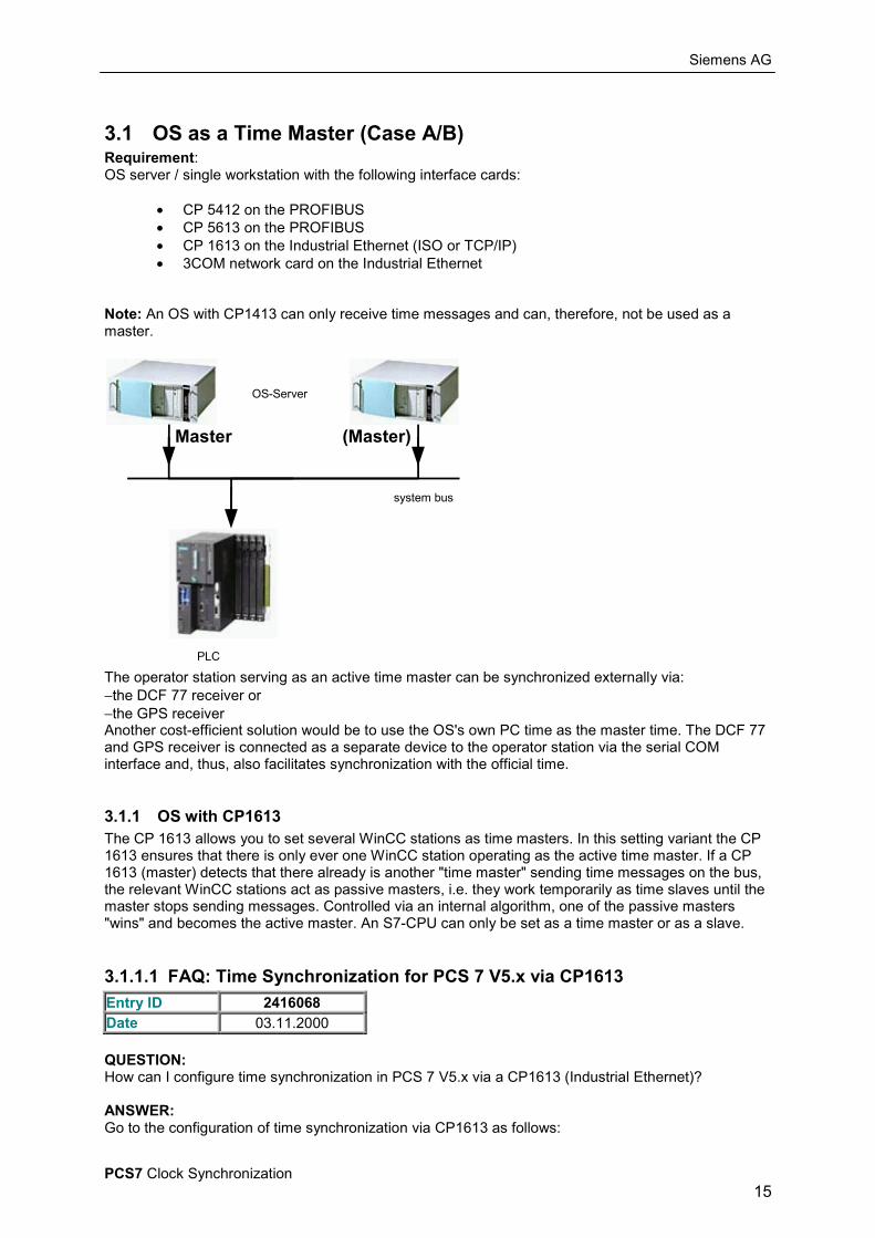
3.1 OS as a Time Master (Case A/B)Requirement:OS server / single workstation with the following interface cards:
• CP 5412 on the PROFIBUS• CP 5613 on the PROFIBUS• CP 1613 on the Industrial Ethernet (ISO or TCP/IP)• 3COM network card on the Industrial Ethernet
Note: An OS with CP1413 can only receive time messages and can, therefore, not be used as amaster.
OS-Server
PLC
system bus
Master (Master)
The operator station serving as an active time master can be synchronized externally via:−the DCF 77 receiver or−the GPS receiverAnother cost-efficient solution would be to use the OS's own PC time as the master time. The DCF 77and GPS receiver is connected as a separate device to the operator station via the serial COMinterface and, thus, also facilitates synchronization with the official time.
3.1.1 OS with CP1613The CP 1613 allows you to set several WinCC stations as time masters. In this setting variant the CP1613 ensures that there is only ever one WinCC station operating as the active time master. If a CP1613 (master) detects that there already is another "time master" sending time messages on the bus,the relevant WinCC stations act as passive masters, i.e. they work temporarily as time slaves until themaster stops sending messages. Controlled via an internal algorithm, one of the passive masters"wins" and becomes the active master. An S7-CPU can only be set as a time master or as a slave.
3.1.1.1 FAQ: Time Synchronization for PCS 7 V5.x via CP1613Entry ID 2416068Date 03.11.2000
QUESTION:How can I configure time synchronization in PCS 7 V5.x via a CP1613 (Industrial Ethernet)?
ANSWER:Go to the configuration of time synchronization via CP1613 as follows:
Siemens AG
PCS7 Clock Synchronization16
Note:If you are using SIMATIC PCS 7 V5.0 + SP1 and configure the CP1613 as time master, then you needthe Hotfix 1 for this version of PCS 7. The hotfix is available in Entry ID 2326215 on the website ofSIMATIC CUSTOMER SUPPORT.
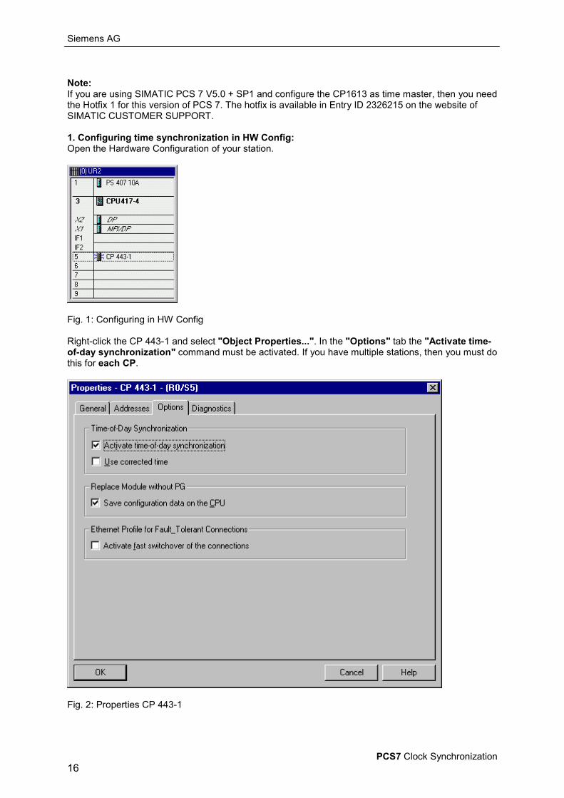
1. Configuring time synchronization in HW Config:Open the Hardware Configuration of your station.
Fig. 1: Configuring in HW Config
Right-click the CP 443-1 and select "Object Properties...". In the "Options" tab the "Activate time-of-day synchronization" command must be activated. If you have multiple stations, then you must dothis for each CP.
Fig. 2: Properties CP 443-1
Siemens AG
PCS7 Clock Synchronization17
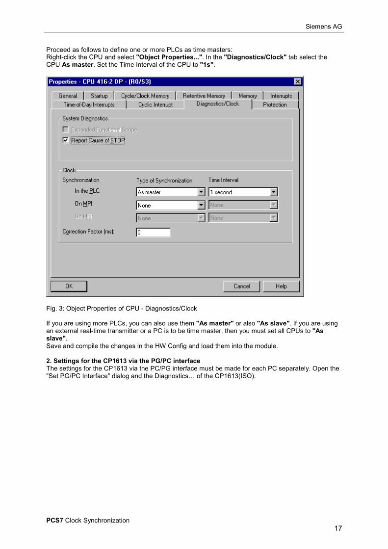
Proceed as follows to define one or more PLCs as time masters:Right-click the CPU and select "Object Properties...". In the "Diagnostics/Clock" tab select theCPU As master. Set the Time Interval of the CPU to "1s".
Fig. 3: Object Properties of CPU - Diagnostics/Clock
If you are using more PLCs, you can also use them "As master" or also "As slave". If you are usingan external real-time transmitter or a PC is to be time master, then you must set all CPUs to "Asslave".Save and compile the changes in the HW Config and load them into the module.
2. Settings for the CP1613 via the PG/PC interfaceThe settings for the CP1613 via the PC/PG interface must be made for each PC separately. Open the"Set PG/PC Interface" dialog and the Diagnostics… of the CP1613(ISO).

Siemens AG
PCS7 Clock Synchronization18
Fig. 4: Setting the PG/PC interface
In the "IE Net Diagnosis" tab you activate "Correct time of day".
Fig. 5: SIMATIC NET Diagnosis CP1613
Siemens AG
PCS7 Clock Synchronization19
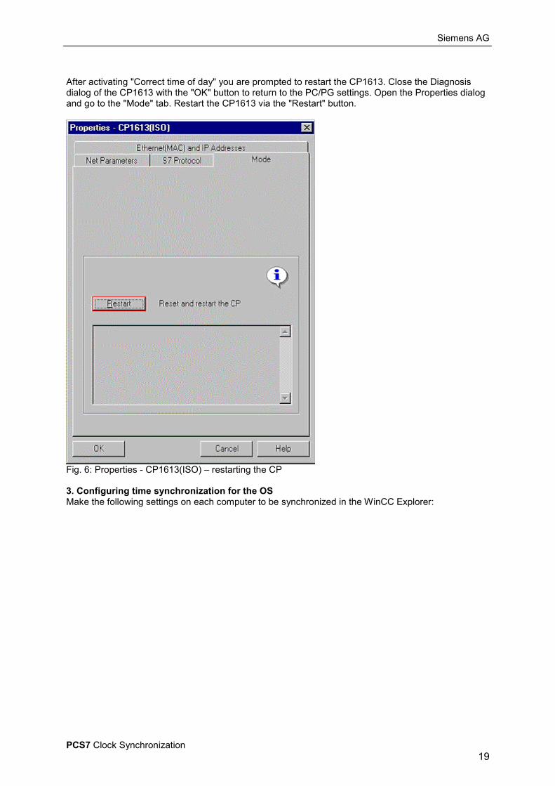
After activating "Correct time of day" you are prompted to restart the CP1613. Close the Diagnosisdialog of the CP1613 with the "OK" button to return to the PC/PG settings. Open the Properties dialogand go to the "Mode" tab. Restart the CP1613 via the "Restart" button.
Fig. 6: Properties - CP1613(ISO) – restarting the CP
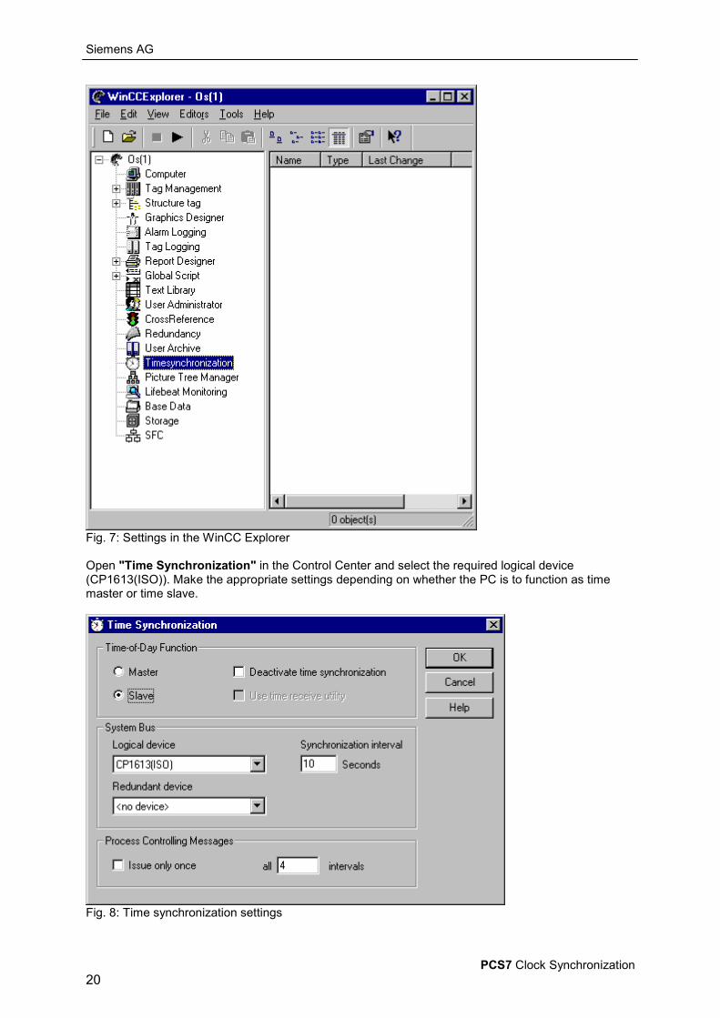
3. Configuring time synchronization for the OSMake the following settings on each computer to be synchronized in the WinCC Explorer:
Siemens AG
PCS7 Clock Synchronization20
Fig. 7: Settings in the WinCC Explorer
Open "Time Synchronization" in the Control Center and select the required logical device(CP1613(ISO)). Make the appropriate settings depending on whether the PC is to function as timemaster or time slave.
Fig. 8: Time synchronization settings
Siemens AG
PCS7 Clock Synchronization21
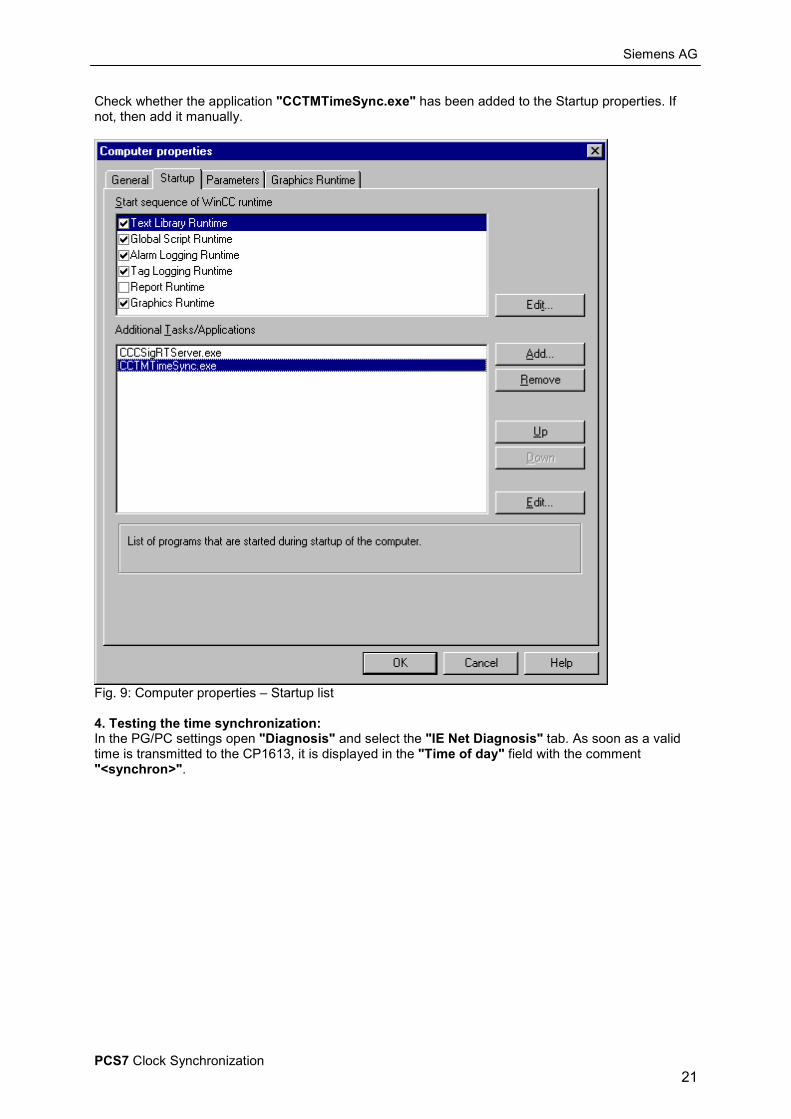
Check whether the application "CCTMTimeSync.exe" has been added to the Startup properties. Ifnot, then add it manually.
Fig. 9: Computer properties – Startup list
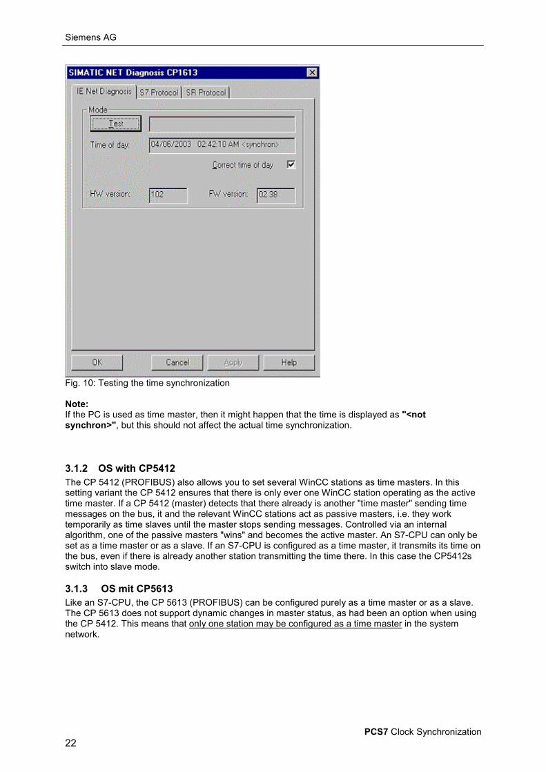
4. Testing the time synchronization:In the PG/PC settings open "Diagnosis" and select the "IE Net Diagnosis" tab. As soon as a validtime is transmitted to the CP1613, it is displayed in the "Time of day" field with the comment"<synchron>".
Siemens AG
PCS7 Clock Synchronization22
Fig. 10: Testing the time synchronization
Note:If the PC is used as time master, then it might happen that the time is displayed as "<notsynchron>", but this should not affect the actual time synchronization.
3.1.2 OS with CP5412The CP 5412 (PROFIBUS) also allows you to set several WinCC stations as time masters. In thissetting variant the CP 5412 ensures that there is only ever one WinCC station operating as the activetime master. If a CP 5412 (master) detects that there already is another "time master" sending timemessages on the bus, it and the relevant WinCC stations act as passive masters, i.e. they worktemporarily as time slaves until the master stops sending messages. Controlled via an internalalgorithm, one of the passive masters "wins" and becomes the active master. An S7-CPU can only beset as a time master or as a slave. If an S7-CPU is configured as a time master, it transmits its time onthe bus, even if there is already another station transmitting the time there. In this case the CP5412sswitch into slave mode.
3.1.3 OS mit CP5613Like an S7-CPU, the CP 5613 (PROFIBUS) can be configured purely as a time master or as a slave.The CP 5613 does not support dynamic changes in master status, as had been an option when usingthe CP 5412. This means that only one station may be configured as a time master in the systemnetwork.
Siemens AG
PCS7 Clock Synchronization23
3.1.4 OS with a 3COM Network Card and BCE
Note: When synchronizing the time via BCE, select the following settings: 1 - 10 sec. grid onthe external time transmitter, 10 sec. grid on the PCS7-OS. The settings and notes for theCP1613 are otherwise relavent for time synchronization.
1. BCE establishes the communication with a network card between PGs/PCs and the bus system. Upto 8 connections can be established between PG/PC. Communication can take place either on the"SIEMENS Industrial Ethernet (ISO)" protocol or the "TCP/IP" protocol. BCE also possesses timesynchronization functions. Time messages can both be sent (time master) and received. The timesynchronization intervals may lie between 1 and 10 sec.
2. In order to utilize the BCE time synchronization, the "SIEMENS Industrial Ethernet (ISO)" protocol(cf. 4th interface installation) must be installed and an access point (cf. 5th device configuration) mustbe set for the "SIEMENS Industrial Ethernet (ISO)".
3. Network cardBCE connects a PC to the "Industrial Ethernet" system bus using a 3COM network card. This networkcard has to be installed.If this network card has not been installed yet, you can do so via Network -> Properties.You can find further information about the Windows NT network installation dialogs in the MicrosoftWindows NT manual.For further information on installing BCE, go to the BCE Readme file.
4. You can now select the device in the "Local Device" box in WinCCExplorer under TimeSynchronization and configure it as a time slave or time master.
3.1.5 DCF 77 Receiver for WinCC
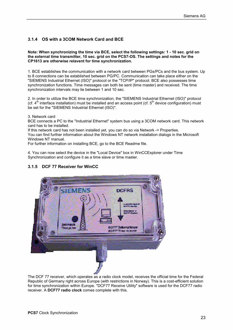
The DCF 77 receiver, which operates as a radio clock model, receives the official time for the FederalRepublic of Germany right across Europe (with restrictions in Norway). This is a cost-efficient solutionfor time synchronization within Europe. "DCF77 Receive Utility" software is used for the DCF77 radioreceiver. A DCF77 radio clock comes complete with this.
Siemens AG
PCS7 Clock Synchronization24
3.1.5.1 FAQ: DCF 77 Receiver for WinCC
Entry ID 1046241Date 03.08.2001
QUESTION:How can I use the DCF 77 time signal in WinCC?
ANTWORT:The DCF 77 signal of the Federal Institute in Mainflingen near Frankfurt transmits the official time forthe Federal Republic of Germany. The transmission is wireless via radio signal at a frequency of 77.5kHz. Upon installation of the DCFRS you also get this radio clock facility on your PC. WinCC takes thesystem time of your computer. In order to get the exact radio signal, proceed as follows.
1. Switch on your PC.2. Insert the supplied driver floppy disk into the floppy disk drive (usually drive A:)3. Install the driver software.4. Activate the DCF 77 receiver service.5. Connect the DCF 77 receiver cable to the selected COM port.6. Adjust the receiver so that the control LEDs flash every second.
If you can't get a clear reception, check the following:
• Make sure that the receiver is as far away as possible from PCs, monitors, laser printers,motors, motor drives or other simple sources of interference.
• Also keep the receiver as far away as possible from metal surfaces and reinforced steel.• Set up the receiver parallel to the transmitter antenna. The transmitter antenna is located near
Frankfurt am Main. Also take the side of the building facing Frankfurt.
Entry ID 1104199Date 21.09.1999
QUESTION:The LED flashes regularly every second. Why is the time signal nevertheless not received?
ANSWER:You have not installed the NT driver of the DCF 77 radio clock receiver properly. You have correctlyconnected the radio clock to a COM interface. The LED flashes regularly every second. Neverthelessthe time signal is not received (in the event display is the last event for DCF77 = DCF77START/STOP time signal reception too bad).
This might be due to a bad reception signal or due to the fact that the FIFO is activated for the COMinterface.
Remedy:
1. Press the "Start" button and select "Settings ".2. Select "Control Panel".3. Double-click the "Connections" icon.4. Select the COM interface to which the radio clock receiver is connected.5. Click "Settings" and then "Extended".6. Remove the check mark from in front of the "FIFO activated" item.7. Exit all menus with "OK".8. Restart the computer.

Siemens AG
PCS7 Clock Synchronization25
3.1.6 GPS Receiver for WinCC
The GPS (Global Positioning System) works supra-regionally and is independent of national timetransmitters because the system is based on 24 satellites which use the time on the on-board clocks.As Windows is installed on the operator station on a country-specific basis, the time transmitted by thesatellite is converted to the valid time in the country. Thanks to the GPS module, SIMATIC PCS 7 canalso be used globally with multi-system time synchronization."DCF77 Receive Utility" software is used for the GPS satellite receiver. A GPS receiver comescomplete with this.
3.1.6.1 FAQ: GPS Receiver (2XV9450-1AR13) for WinCCEntry ID 1069326Date 03.08.2001
QUESTION:How can I use the GPS satellite time in WinCC?
ANSWER:WinCC takes the time from the system time of your computer. In order to receive the exact radiosignal from the GPS satellites, you must proceed as follows:
1. Switch on your PC.2. Insert the supplied driver floppy disk into the floppy disk drive (usually drive A:)3. Install the driver software.4. Activate the DCF 77 receiver service in the Control Panel.5. Connect the WinGPS receiver cable to the selected COM port.6. Adjust the receiver so that it points to the sky.
The DCF 77 receiver service is used. The GPS decoder converts the GPS time signal internally into aDCF 77 signal. This is read by the driver software and transferred to the system time of the PC. youcan't get a clear reception, check the following:
• Point the receiver antenna to the sky.• Make sure that the antenna has as large a clear "view" as possible. If there is a direct
connection between your receiver antenna and the satellite, this is known as visual contact.
Siemens AG
PCS7 Clock Synchronization26
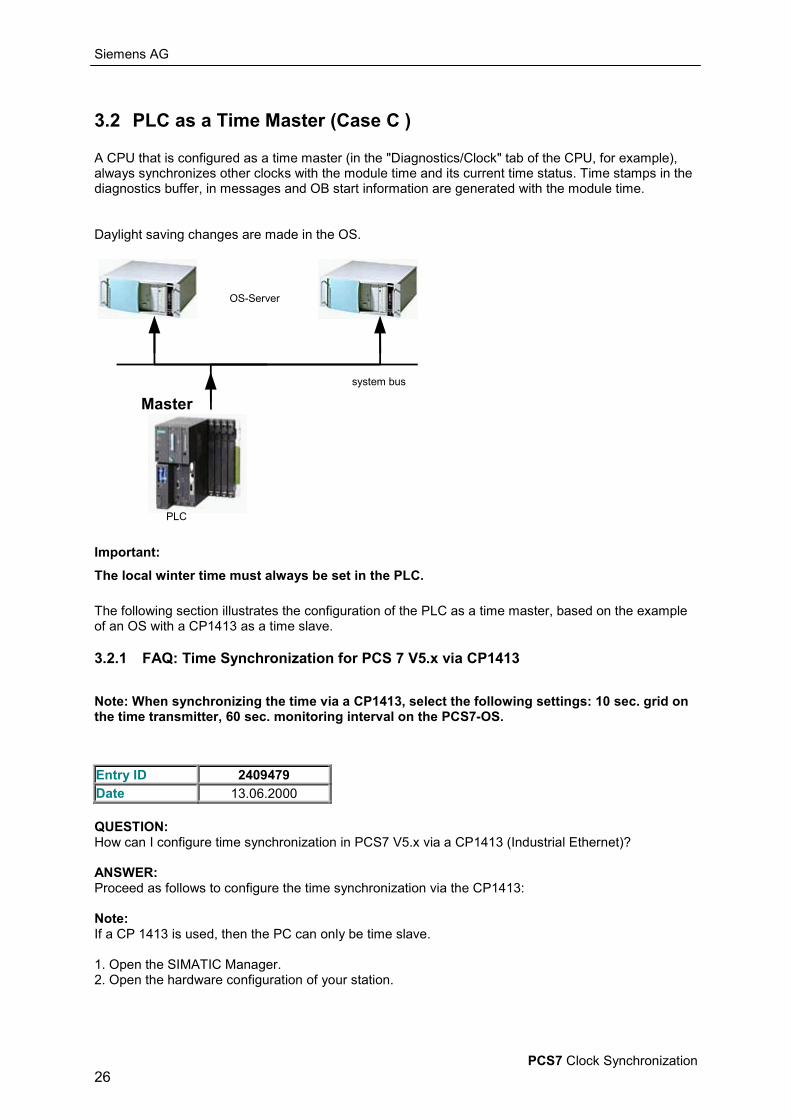
3.2 PLC as a Time Master (Case C )
A CPU that is configured as a time master (in the "Diagnostics/Clock" tab of the CPU, for example),always synchronizes other clocks with the module time and its current time status. Time stamps in thediagnostics buffer, in messages and OB start information are generated with the module time.
Daylight saving changes are made in the OS.
OS-Server
PLC
system bus
Master
Important:The local winter time must always be set in the PLC.
The following section illustrates the configuration of the PLC as a time master, based on the exampleof an OS with a CP1413 as a time slave.
3.2.1 FAQ: Time Synchronization for PCS 7 V5.x via CP1413
Note: When synchronizing the time via a CP1413, select the following settings: 10 sec. grid onthe time transmitter, 60 sec. monitoring interval on the PCS7-OS.
Entry ID 2409479Date 13.06.2000
QUESTION:How can I configure time synchronization in PCS7 V5.x via a CP1413 (Industrial Ethernet)?
ANSWER:Proceed as follows to configure the time synchronization via the CP1413:
Note:If a CP 1413 is used, then the PC can only be time slave.
1. Open the SIMATIC Manager.2. Open the hardware configuration of your station.

Siemens AG
PCS7 Clock Synchronization27
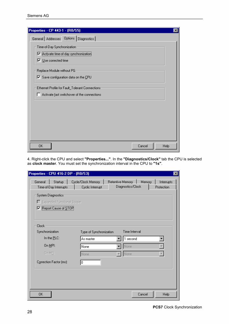
3. Right-click the CP 443-1 and select "Properties...". In the tab "Options" the command "Activatetime synchronization" and "Use displayed time" must be activated. If you have several stations,you must execute this step for each CP.
Siemens AG
PCS7 Clock Synchronization28
4. Right-click the CPU and select "Properties...". In the "Diagnostics/Clock" tab the CPU is selectedas clock master. You must set the synchronization interval in the CPU to "1s".
Siemens AG
PCS7 Clock Synchronization29
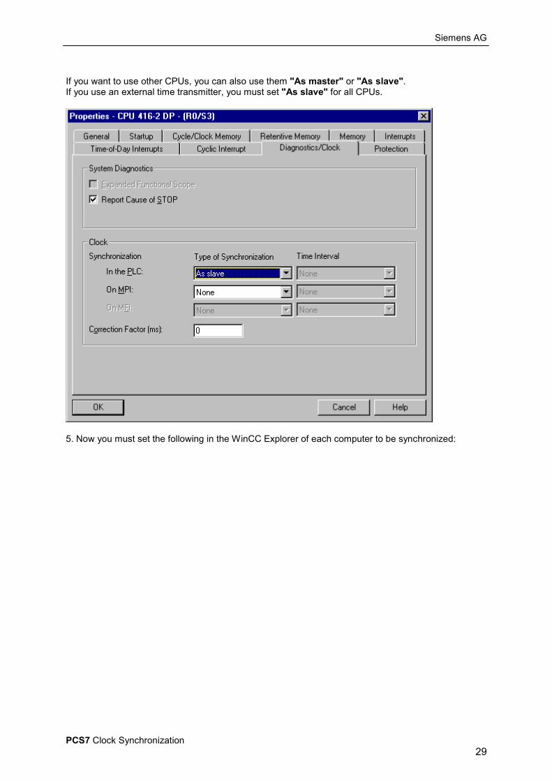
If you want to use other CPUs, you can also use them "As master" or "As slave".If you use an external time transmitter, you must set "As slave" for all CPUs.
5. Now you must set the following in the WinCC Explorer of each computer to be synchronized:

Siemens AG
PCS7 Clock Synchronization30
6. Open "Time Synchronization" in the WinCC Explorer and select the required logical device(/CP1413(256k)/SCP).
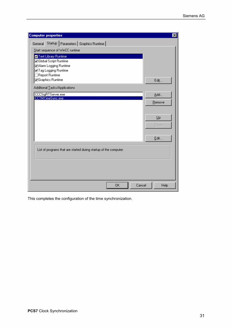
7. Check whether the application "CCTMTimeSync.exe" has been inserted in the runtime propertiesof the computer. If not then add it.
Siemens AG
PCS7 Clock Synchronization31
This completes the configuration of the time synchronization.
Siemens AG
PCS7 Clock Synchronization32
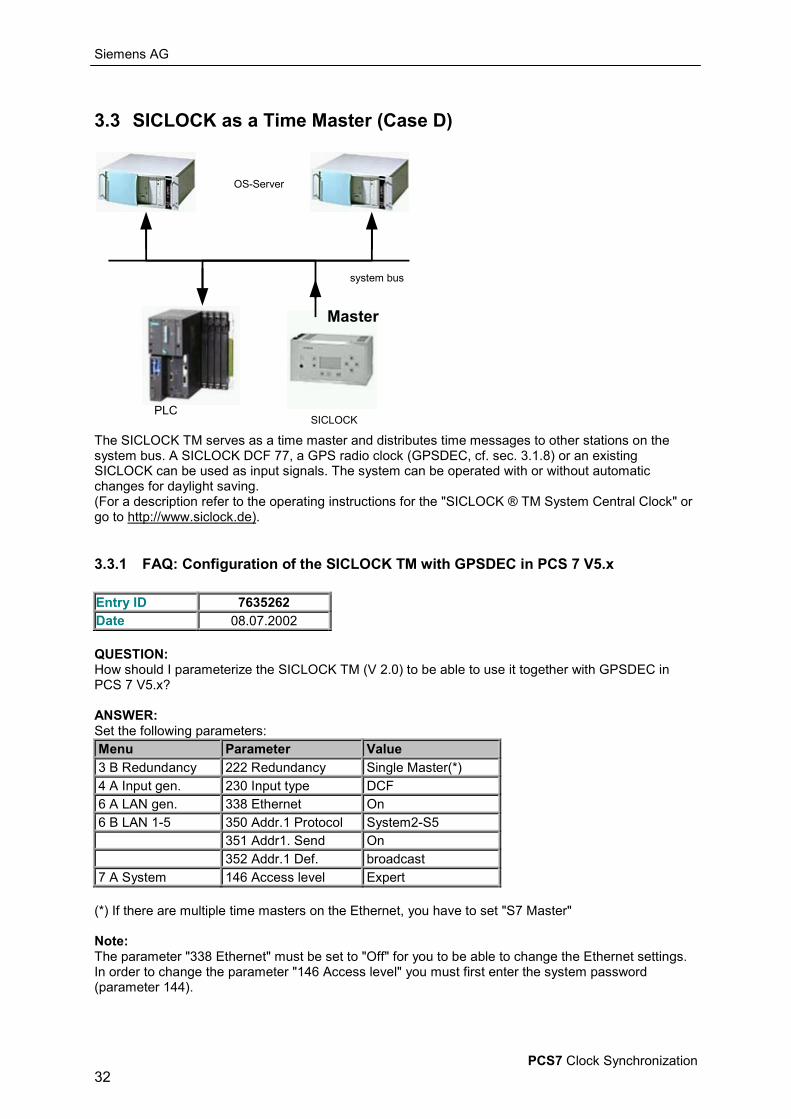
3.3 SICLOCK as a Time Master (Case D)
OS-Server
SICLOCKPLC
system bus
Master
The SICLOCK TM serves as a time master and distributes time messages to other stations on thesystem bus. A SICLOCK DCF 77, a GPS radio clock (GPSDEC, cf. sec. 3.1.8) or an existingSICLOCK can be used as input signals. The system can be operated with or without automaticchanges for daylight saving.(For a description refer to the operating instructions for the "SICLOCK ® TM System Central Clock" orgo to http://www.siclock.de).
3.3.1 FAQ: Configuration of the SICLOCK TM with GPSDEC in PCS 7 V5.x
Entry ID 7635262Date 08.07.2002
QUESTION:How should I parameterize the SICLOCK TM (V 2.0) to be able to use it together with GPSDEC inPCS 7 V5.x?
ANSWER:Set the following parameters:Menu Parameter Value3 B Redundancy 222 Redundancy Single Master(*)4 A Input gen. 230 Input type DCF6 A LAN gen. 338 Ethernet On6 B LAN 1-5 350 Addr.1 Protocol System2-S5 351 Addr1. Send On 352 Addr.1 Def. broadcast7 A System 146 Access level Expert
(*) If there are multiple time masters on the Ethernet, you have to set "S7 Master"
Note:The parameter "338 Ethernet" must be set to "Off" for you to be able to change the Ethernet settings.In order to change the parameter "146 Access level" you must first enter the system password(parameter 144).

Siemens AG
PCS7 Clock Synchronization33
4 Synchronization of PCS7 Systems (Terminal Bus)
4.1 DCF77 Receive Utility
OS-Clients
OS-Server
terminal bus
TCP/IP LAN
The terminal bus is generally set up as a TCP/IP LAN, independent of the system bus.The operator stations communicate with one another on the terminal bus via standard network cards.For the purposes of time synchronization on the terminal bus, the PCS 7 software includes the"DCF77 Receive Utility" for all the OS clients. In order to synchronize timing, a PC with MicrosoftWindows NT must be defined as the time master; its time must be synchronized with the system bus.This task is generally performed by an OS server.
4.1.1 FAQ: Time Synchronization for OS ClientsEntry ID 775131Date 19.06.2002
QUESTION:How do you configure time synchronization for WinCC clients.
ANSWER:
1. Server-client project with non-redundant serversThe clients are synchronized over the system time of the servers. The requirement here is that thecomputers are in the same network. Configuring the time synchronization is done in four steps:
• Install the "DCF77Client" tool on all clients that are to be synchronized. This software is on theWinCC CD (V4.02 and higher) under "Smart Tools > DCF77Client".
• After installation start the tool via "Start > Settings > Control Panel > DCF77".• In the "Connection" field you must enter the server computer (time master).
Siemens AG
PCS7 Clock Synchronization34
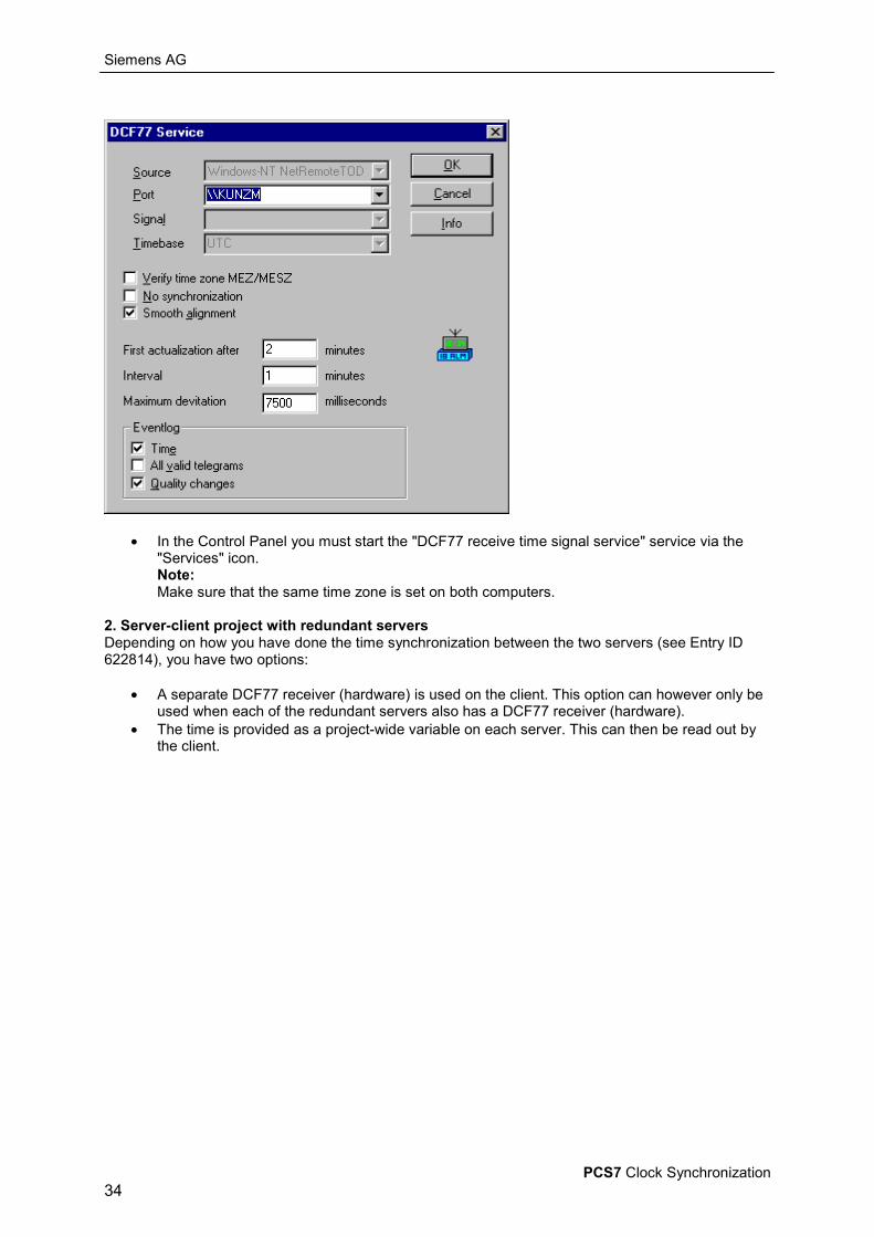
• In the Control Panel you must start the "DCF77 receive time signal service" service via the"Services" icon.Note:Make sure that the same time zone is set on both computers.
2. Server-client project with redundant serversDepending on how you have done the time synchronization between the two servers (see Entry ID622814), you have two options:
• A separate DCF77 receiver (hardware) is used on the client. This option can however only beused when each of the redundant servers also has a DCF77 receiver (hardware).
• The time is provided as a project-wide variable on each server. This can then be read out bythe client.
Siemens AG
PCS7 Clock Synchronization35
Abbreviations
TMes Time messageWT Winter timeST Summer time
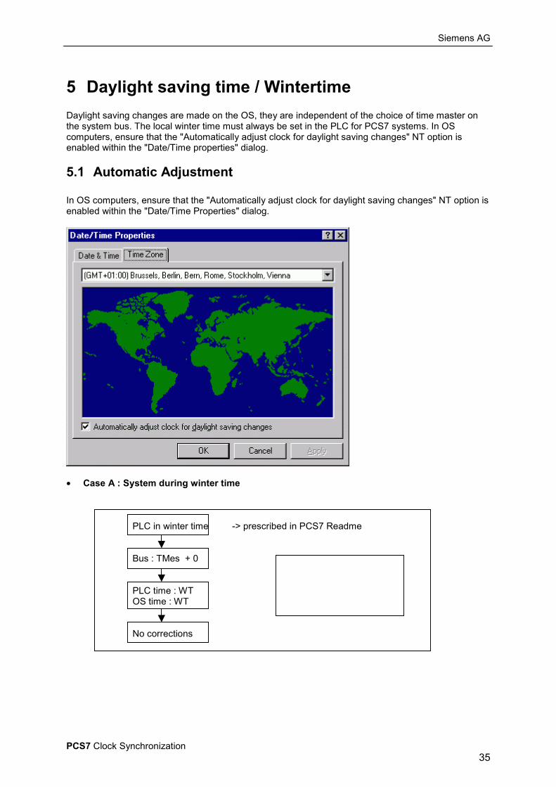
5 Daylight saving time / WintertimeDaylight saving changes are made on the OS, they are independent of the choice of time master onthe system bus. The local winter time must always be set in the PLC for PCS7 systems. In OScomputers, ensure that the "Automatically adjust clock for daylight saving changes" NT option isenabled within the "Date/Time properties" dialog.
5.1 Automatic Adjustment
In OS computers, ensure that the "Automatically adjust clock for daylight saving changes" NT option isenabled within the "Date/Time Properties" dialog.
• Case A : System during winter time
PLC in winter time -> prescribed in PCS7 Readme
Bus : TMes + 0
PLC time : WTOS time : WT
No corrections
Siemens AG
PCS7 Clock Synchronization36
• Case B : System during summer time
In summer an OS automatically adjusts the PLC messages to summer time
PLC in winter time
Bus: TMes + 1 � The "Use corrected time" option should be disabled in theCP443-1
PLC time : WTOS time : ST
Display the PLC messagesin the OS with ST
Warning : If the "Use corrected time" option is enabled in the CP443-1, the PLC messages aretransmitted with ST and are automatically displayed in WinCC with ST plus 1 hour, i.e. they areincorrect! This also happens if the PLC is operated by adjusting it manually to summer time.
In either of these cases, FAQ 7604251 provides a means of changing the behavior of WinCC:
5.1.1 FAQ: Messages in Runtime are Running One Hour AheadEntry ID 7604251Date 29.08.2001
QUESTION:Once daylight saving time has been set in the automation system, the messages are given a timestamp that is daylight saving time plus 1 hour. Why is this so and how can I correct it?
ANSWER:The time stamp from the automation system does not contain any information about whether daylightsaving time or winter time is to be interpreted. Time zone divisions are not taken into account either.If time information (e.g. message) is sent to the Operator Station, then during daylight saving time onehour is added automatically. The Operator Station assumes that winter time is always set on theautomation system. This is the case normally. However, if the automation system is automatically setto daylight saving time by another time transmitter, then another hour is still added in the OperatorStation, because the Operator Station has not received any information about this daylight savingtime/winter time synchronization.
To avoid having another hour added to the daylight saving time in the automation system, you mustmake a change in the Registry.Under the code"HKEY_LOCAL_MACHINE\SOFTWARE\Siemens\WinCC\NormDLL\NrmS7pmc"the double-word entry "NotConsiderDaylight" must have the value 1.
Important:In general, no warranty can be given for direct changes in the Registry, because this is entirely theresponsibility of the user. In any case it is recommended to make a backup of the registry beforeproceeding as described below. Furthermore, these settings are computer-specific. This means thatwhen copying the project to another computer, the settings have to be made again.
Siemens AG
PCS7 Clock Synchronization37
5.2 Manual AdjustmentThe "Automatically adjust clock for daylight saving changes" NT option is disabled within the"Date/Time Properties" dialog, and the system clock can be adjusted manually. The system is likely tobehave as follows within the OS.
5.2.1 FAQ: Problems Arising when Adjusting the System TimeEntry ID 2042303Date 15.08.2000
QUESTION:What should you watch out for when changing the system time? (Careful when traveling across timezones)
ANSWER:When changing the system time you should note that this might cause considerable problems.Therefore always take appropriate safety precautions when changing the time.The effects that arise are not product-specific, but a characteristic of all systems that archive usingtime stamps, control processes, sort or measure the time.The problems increase with the size of the time period changed, the time during which the systemruns with the wrong time and the degree to which the time-dependent functions are used.The effects occur in particular when the clock of a system is set to a date in the distant future, thesystem works a certain amount of time there and then the clock is set back to the "current" time.Typical faults that occur under these circumstances are, for example:
• Non-execution of processes up to the time to which the system was set in the future.• Current values are ignored.
Often databases are filled with values from the future. Current values thus have a time stampwhich for the database are way back in the past. The current values are therefore eitherdeleted or ignored.
• Creation of defective lists that use the time as sort criterion.
Example:A PC system clock is set to a date that is three months ahead. The computer then runs for severalhours and is then set back to the "current" time.The following effects might occur:
• The cyclically activated virus scanner might only be executed again after the real time haspassed the time to which the system clock has been set.
• During the time that the computer clock is set in the future the archiving programs (e.g.Storage) delete or relocate all the values that appear to be several months old.
• Values from the time period in the future are displayed as the latest entries in lists andarchives.
• In the case of full cyclic archives, the newly arrived data is recognized as "old" values anddeleted.
• There are restrictions of NT system services such as directory replication service, hard diskdiagnostics, print job management, password expires, summer time/winter time changeoveretc.
Remedy:Since changing the time can have numerous side effects which in turn influence each other, it is notpossible to make a general statement about the outcome for the system. The safest way would be toset up the system anew.In practice it can look like this:Before changing the time, you create an image of your system and import it again after making yourtests.
Siemens AG
PCS7 Clock Synchronization38
5.3 Loading in Images
5.3.1 FAQ: Daylight Saving Changes when Loading in Images
Entry ID 2042075Date 03.04.2000
QUESTION:What should I watch out for with regard to the winter time/daylight saving time changeover whenimporting images?
ANSWER:During the daylight saving time (winter time) you have created a back-up file (Image) with thecomplete image of your hard disk. When you import this image to a computer whose system clock isset to a data with winter time (daylight saving time), this might lead to the system clock is set one hourback (forward) when the operating system starts up.The operating system obviously presumes that the computer has not operated for a longer period oftime and does the apparently overdue changeover of the PC real-time clock
WARNING:This behavior can lead to critical states of the system. There is a particularly high risk if the computerconcerned is used as time master.
Siemens AG
PCS7 Clock Synchronization39
Annex
A SICLOCK / DCF77 /GPS
• General Information about SICLOCK
When it comes to a reliably synchronized system, the following points are particularlyimportant for ensuring that the clocks in the individual controllers and computers don't go outof sync the first time an error occurs:1. The system is synchronized by a single or redundant main clock (SICLOCK TM).2. The radio synchronization of the plant is connected exclusively to the main clock. If the radiosynchronization fails, the system is still uniformly synchronized by the main clock which runs withquartz operation. In the case of SICLOCK, the quartz operation following radio reception reaches adegree of precision of 1 to 2 ppm due to the recalibration of the quartz. The instant alarm messagefrom SICLOCK TM facilitates a rapid repair of the radio synchronization (provided the failure is not dueto a temporary fault in the transmitter). The minimal time deviation which occurred during the deviationcan be reduced again imperceptibly by activating the micro mode in SICLOCK TM, without a singletime interval occurring which is not equal to one thousand milliseconds. Absolutely clean timestamping is always possible.3. Any further main clocks that may be required in large systems are not connected to the radiosynchronization, they are synchronized by the master main clock.4. The main clock distributes the time to all the systems being synchronized. Particular care is to begiven to the choice of transmission media used, electrical or optical.The benefits of fiber-optic cables are especially apparent in the case of strong interference fields.SICLOCK supports optical distribution both via LAN and via serial asynchronous point-to-pointconnections.
• General Information about GPS
GPS: Global Positioning SystemLocation: 24 satellites on 6 orbits at an altitude of 20184 kmCarrier frequency: 1.574 GHzRange: Total surface of the earthTime message: Greenwich MeantimeSynchronization: Only necessitates receipt of a signal from one of the satellites
Special features of GPS reception under industrial conditionsThe normal faults occurring in industrial applications, including electric arcs, have a frequency rangebelow the GPS carrier frequency of 1.574 GHz.This means that GPS antennas can be mounted in any location where there is a visible link to the sky.Optimum reception results are achieved if the antenna's "viewing angle" is perpendicular to the sky,pointing upwards. In the case of smaller angles, situations may arise occasionally where there is nosatellite in the reception window, causing synchronization to fail temporarily.Take care not to erect the antenna in locations where it is in danger of being struck by lightning.In some cases the antenna nay also be attached to the inside of high windows.
Siemens AG
PCS7 Clock Synchronization40
• General Information about DCF77
DCF77: Official German time signal transmitterLocation: Mainflingen near Frankfurt (am Main)Transmission output: approx. 28 kWCarrier frequency: 77.5 kHz stabilized with high precision, can be used as a frequency normal.Range: approx. 2000 kmModulation type: AMEncoding: Second pulses lasting 0.1s or 0.2 sec. respectively (corresponding to 0 or 1)Time message: 58 second pulses long, containing:
• time,• date,• 3 parity bits,• summer time / winter time detection and• preparatory bits for daylight saving changes, as well as switching
seconds.Synchronization: The transmitted time becomes valid on the first pulse after the 59th omitted
pulse.Year number: Two digit transmission; the recipient must know the current century.
Special features of DCF77 reception under industrial conditionsGeneral differences between industrial use and domestic use:
• there is a number of strong sources of interference, generally nationwide,within the range of the DCF carrier frequency;
• there are radio wave-shielding effects caused by buildings, metal façades,heavily steel-reinforced concrete walls and other electrically conducting,earthed objected;
• there are long cables running between the antenna and synchronizedcontroller;
• there is an increased risk of lightning strikes;• lightning arresters may have induction effects on the antenna cable in the
event of a lightning strike.This gives rise to the following requirements for the DCF reception system:
• the interference power needs to be minimized in relation to the output of theeffective DCF signal at the point of reception;
• the antenna needs to be kept at least 0.5 meters away from the wall orconductive surface, otherwise, the reception field strength will be reducedseverely, the closer the antenna is to the wall;
• prevent interference to the cable between the antenna and the synchronizedcontroller, in particular if the cable is laid in cable ducts with electricity cables;
• the antenna should be erected inside a building, if possible;• the antenna cable should be kept as far away from lightning arresters as
possible and, if possible, should be laid at right angles to them.In order to ensure that our antennas are suitable for industrial application, we have developedthe following properties:
• In order to minimize the interference received, we have inserted a 2-stagefilter with sharply falling edges upstream of the actual long-wave receiver,giving the receiver a very narrow bandwidth. This reduces the receiver'soperating temperature range from 0 to 60 degrees Celsius.
• We maintain the minimum spacing of 0.5 meters with the aid of our specialplastic antenna frame which, regardless of where it is installed (any inclinedwall, flat roof or under the roof) can be screwed together differently so as toensure that the antenna is always optimally aligned to the transmitter. Otherthan the four holes which have to be drilled to screw it on, no other workneeds to be done by the customer.
• In order to eliminate interference in the antenna cable with antenna signallevels in the milli-volt or micro-volt range, we have installed the long-wavereceiver into the antenna and, instead of the antenna receive signal, transmitthe demodulated and amplified receive signal to the controller in the form of a20mA current-loop signal. This is how our active antenna came about; in
Siemens AG
PCS7 Clock Synchronization41
addition to the ferrite rod, it contains the complete wavelength receiver, notjust a transistor for adapting the impedance to the cable. No adverse effectshave been encountered so far using a shielded cable with a pair of twistedstrands, even when they are laid in cable routes which are exposed to veryheavy interference several hundred meters apart. The power supply to thereceiver takes place via a current loop on which the demodulated DCF signalis also transmitted.
• The antenna has to be erected inside a building, generally close to a windowfacing in the direction of Frankfurt (am Main). A location also has to be foundwhich experiences little or only temporary interference.We can survey potential good site(s) for you using our battery-operatedspecial equipment!
• Induced surges in the 20mA cable are rendered harmless to a certain degreeby a surge protector at the output of the active antenna and by using anoptocoupler at the input of the controller.


![Simatic Getting Started PCS7[1]](https://img.dokumen.tips/doc/110x75/577c7ab41a28abe05495ef1d/simatic-getting-started-pcs71.jpg)