Embed Size (px)
Citation preview

PCI Compliance TestingBarbara P. Aichinger
FuturePlus Systems15 Constitution Drive
Bedford, NH 03110 USATEL:603-471-2734 FAX:603-471-2738
e-mail:[email protected]
Agendar Overview of the PCI SIG Compliance Test
Programr Case Study System
m Timing Verificationm Performancem Signal Integrity
r Summary and Questions
PCI Special Interest Groupr The PCI SIG (www.pcisig.com)
m 500+ member companiesm Technical Supportm Control the Specification and revisionsm Source of new PCI technology related
developmentsm Host the PCI Compliance Workshops
The address and phone numbers for the PCI SIG are as follows:PCI2575 NE Kathryn #17Hillsboro, OR 97124 USA1-800-433-5177 (inside the US)1-503-693-6232 (outside the US)FAX: 503-693-8344e-mail: [email protected] SIG member technical support: [email protected] hours: 8:30am-4:00 pm West Coast USA time
PCI SIG Compliance Programr Program Objectives
m Increase ramp of PCI products in the marketby having trouble free interoperability for theend-user
m Focus only on the PCI content of the productas much as possible
m Increase acceptance of PCI by emphasizingdesign discipline and adherence to the spec
The PCI Special Interest Group realizes the importance ofinteroperability for PCI products. With this objective in mind the PCISIG has put in place a PCI Compliance Program.
What is PCI Compliance Testing?r PCI Compliance Test Checklist
m Basic PCI requirementsr PCI Compliance Workshops
m Rigorous System Testingm Attracts many different system and add-in
card vendorsr There is no PCI Compliance certificate or label
you can put on your product!m A voluntary effort by the PCI industry to police
itselfThe PCI Compliance Program is a program that promotes PCItesting. This testing has two forms. The first, is for designers to usethe PCI Compliance Checklist to ensure that their designs meet allthe rules of the specification on an item for item basis. The secondtype of testing is to insure that these designs all work together invarious system configurations running various software applications.This is, for the most part, a voluntary program. There is no formalcertification process and no certificate or label awarded to those whopass.
PCI Compliance Workshopsr Sponsored by the PCI SIGr Held 2 to 3 times a yearr Purpose:
m Provide a forum for devices to be testedtogether
m Get engineers talking about how to make PCItruly “Plug and Play”
The PCI Special Interest Group has held eleven PCI ComplianceWorkshops to date. The most recent was last week here in Berlin. AllPCI Compliance Workshops are available to PCI SIG members andthe dates and locations for future workshops will be listed on the PCISIG home page www.pcisig.com.
The PCI Compliance Checklistr Written by members of the PCI Special Interest
Groupr The purpose of the checklist is to promote
interoperability in the PCI industryr Required to get on the PCI SIG Integrator’s listr Current Rev is 2.1r Found on PCI SIG web page (www.pcisig.com)
The PCI industry is fortunate to have a companion specification ofsorts called the PCI Compliance Checklist. The purpose of the PCICompliance Checklist is to promote interoperability within the PCIindustry. It is technical and detailed. The checklist was written bymembers of the PCI Special Interest Group. The PCI SIG formed,and continues to form, committees that address various concerns ofthe PCI industry. A committee was put together to address test, andthe Checklist is a result of that work. FuturePlus Systems served onthat committee.The checklist can be used during both the design and verificationphases of the product. At design time an engineer can use thechecklist as a guide for the type of functionality that is required. Atverification time the checklist can be used as a starting point for adesign verification test suite.
What’s in the PCI Compliance Checklist?r The checklist is a list of items that detail proper PCI
bus operation.

r The checklist is divided into the following areasm Motherboards
4 Electrical
m BIOSm Components
4 Electrical4 Configuration4 Protocol
m Expansion Cards4 Electrical4 Configuration4 Mechanical
m Systems4 Mechanical
The Checklist is a minimum set of tests that must pass on every designand is divided into 5 main sections:Motherboard, BIOS, Component, Expander cards and System. Underthese headings you can see the sub sections of Electrical,Configuration, Protocol and in the case of Systems, Mechanical.
Checklist items
r Some checklist items can be verified by inspection ofthe design.
m For exampleME12-”The following signals are pulled up with a resistor ofthe correct value: FRAME#, TRDY#, IRDY#, DEVSEL#,STOP#, SERR#, PERR#, LOCK#?”r Some checklist items are best verified in simulation
and then in the labm For example
4 CE42-”All bussed signals are driven valid between2ns and 11ns after CLK for 33Mhz PCI, between 2and 6ns for 66Mhz PCI”
Included here are a couple items from the Checklist. As can be seen,some of the checklist items are more appropriate for a design review.Others can be tested in simulation and then in the lab.
Integrator’s Listr Confidential to members of the PCI SIGr Inclusion on the list cannot be used for marketing
purposesr Purpose:
m Encourage interoperability testingm Encourage compliance testingm Acknowledge those who have passed
The Integrators List was devise by the PCI SIG in order to promote PCItesting and interoperability. It is a list of known good PCI products. TheIntegrators List is confidential and only available to PCI SIG members.
Integrators List cont.
r To get on the List:m PCI SIG Memberm Satisfactory completion of the PCI Compliance
Checklistm Passed test criteria at the PCI Compliance
Workshopm Product must be production ready
For a product to be listed it must :
• Have completed and satisfactory PCI Compliance Checklist on file atthe PCI SIG
• Have passed the test criteria set forth at the PCI ComplianceWorkshops
• Be production ready
This list is updated after each workshop. And contains the followingdisclaimer:“The PCI Special Interest Group disclaims all warranties and liabilities forthe use of any product listed in this document and assumes noresponsibility for any errors that appear in this document nor for thecompleted PCI Checklist and/or compliance testing performed for any ofthe listed products.
Embedded PCI Designsr Most PCI design applications can use the tools
developed for the PC PCI industryr The protocol and timing rules of PCI are the same
regardless of applicationr The embedded PCI designer must look for:
m Tools with compatible form factorsm Chip based tools
Industries that choose to leverage the PCI technologies in theirapplications will be able to take advantage of the numerous tools anddocuments developed for the PC PCI industry. The embedded designermust consider their form factor when choosing PCI tools.The current leading form factor for the PCI technology is the desktopform factor, second is CompactPCI and PMC (PCI Mezzanine).
How do I get my design tested?r PC Industry
m Join the PCI SIG4 Get the PCI Compliance Checklist4 Attend the PCI Compliance Workshops4 Work with other vendors to do interoperability
testingï Go well beyond the checklist and do robust
system testing and verificationr Embedded PCI
m Get the PCI Compliance Checklistm IF your design can be tested in PC’s attend the
workshops.Currently the compliance program is geared toward the PC industry.The embedded PCI designer can use the tools and the compliancechecklist to accomplish a similar level of testing. CompactPCI and PMCtools are readily available on the market.
Compliance Test Summaryr PCI Designers have the advantage of a well written
specification and test checklistr Use the Compliance Test Checklist
m At design timem For verification
r However, the Checklist provides only a minimum setof tests
r Proper electrical testing will insure interoperability inthe field
r If your designs can be tested in a PC, attend thecompliance workshops
The PCI designer is fortunate to have a well written specification that hasbeen extensively reviewed and supplemented with a Compliance TestChecklist. The PCI designer can use the Compliance Test Checklistboth at design time and at verification time. However, the PCI designerwill have to go well beyond the PCI Compliance Checklist in order toensure that their design is compliant. Rigorous system andinteroperability testing along with examination of design margins willensure a reliable, compliant design.
Case Study Systemr Ziatech CompactPCI System
m Pentium CPUm PCI Bus (10 slots)
4 Ethernet (bus mastering)4 SCSI
How the analysis was doner The Test Equipment used
m HP Prototype Analyzer HP16505A4 HP16500C mainframe
ï HP16555A logic analyzersï HP 16534A Oscilloscopeï HP 16517A/518A high speed timing cards
4 System Performance Analysis Softwarem CompactPCI Preprocessor
4 with extender card functionalityHere is a list of test equipment that was used to monitor the system. ACompactPCI Preprocessors was used to provide connection from thetest equipment to the PCI bus under test.
CompactPCI Preprocessor
The CompactPCI Preprocessor is a 3U form factor (extended length)that allows a convenient connection between your HP logic analyzer anda CompactPCI system. All the signals on the CompactPCI connectorare brought to the logic analyzer through high impedance matchingtermination networks. No flying leads! To prevent reflections from theadded etch length of the extender card connector high speed clampingdiodes are mounted near the extender card connector. TheCompactPCI Preprocessor can also operate in the system slot with theCPU on the extender card connector. This allows the viewing of all theREQ# and GNT# signals. The product comes with complete
configuration files for all HP logic analyzers and a PCI InverseAssembler.For more information on this product please visit our WEB site atwww.futureplus.com.
Workspace
Here is the workspace that was used to study our CompactPCI system.The single icon on the left is the logic analyzer. As the work progressed,scope and high speed timing card icons were added. The icons on theright are the various measurement windows. The data can be put inchart form, viewed as a waveform or as a state listing. It can even befiltered so only the cycles of interest are viewed.
What did we look for?r Timing Verificationr Performance Characteristicsr Signal Integrity
Timing Verificationr We tested the Command lines for setup per checklist
item CE46:m To make the measurement
4 Connect the C/BE[3::0]# lines and the CLK to thehigh speed timing card via the CompactPCIPreprocessor test points
4 Use the setup and hold macro to program a setuptime of 6ns to the rising edge of CLK
m Use this technique to test any setup and holdtime that you have specified for your design
r Slot to Slot clock skewThe HP16517A/518A was chosen for this particular test because it hasbuilt in timing violation trigger macro’s that make triggering on setup andhold violations very easy.This test dictates that all bussed signals be examined. For this exampleonly the command lines will be tested. The HP16517A was attached tothe test points of the CompactPCI Preprocessor. The HP16517A /518setup and hold macro was programmed for 6 ns since the macro canonly be programmed in increments of 2 ns. This does not mean we willmiss the violation. It means we have set a slightly stricter criteria. If theanalyzer triggers we will be able to make a measurement down to aresolution of 250 ps and thus rule out any “false positives”. What thisequipment will do is monitor the bus and if a violation is ever detected itwill trigger. This means that the command lines will be tested againstEVERY rising edge of the clock for this violation. The HP16517A/518Ahas up to 80 channels so many signals can be examined at once. Afterthe command lines we looked at slot to slot clock skew.
Setup and Hold on C/BE lines

Timing verification is an important part of most digital designs and PCI isno exception. In fact, timing seems to be the major headache for mostPCI designers. Test CE46 from the PCI Compliance Checklist saysthat all bussed inputs must require no more than 7ns of setup time .This particular specification has caused the most headaches for PCIinterface and motherboard designers. This requirement also implies thatthe system must provide this setup at all PCI inputs.Our case study system did not cause the high speed timing card totrigger. Therefore no violation was found. In order to characterize oursystem we backed off the trigger until we found the setup/hold that thesystem was operating at. This is a good method of measuring the timingmargins of the system.
Tval on C/BE lines
Test CE42 is the drive valid spec for PCI. All bussed signals must bedriven valid 2 to 11ns after the rising edge of the clock (33Mhz). Ourcase study system showed no Tval violation on the C/BE signals andthose signals were driven valid within 5ns.
Corresponding State Listing
This slide shows the corresponding state listing, triggered from the highspeed timing card. If a violation existed this would show the bus master,the data and the transaction type that was present when the violationoccurred.
FRAME# setup/hold
This slide shows FRAME# and the PCI clock. Tval was measured atapproximately 5ns which provides the system with ample setup time.
Clock Skew (slot 1 to 5)
We also examined the system for clock skew. This picture shows noviolation of the PCI Clock Skew specification in our case study system.Per the PCI Specification section 4.3.1 “The maximum allowable clockskew is 2 ns.” The measurement was made at the CompactPCIPreprocessor test points (close to the connector).
Clock Skew (rising edge)

This slide shows the rising edge of the clock at slot 1 and slot 5.
Performance Characteristicsr GNT# to the start of transaction
m 8 clocks maximum, 2 to 3 clocks recommendedr Bus Utilization
m Wait statesm Idle states
The PCI SIG has compiled a list of PCI “Do’s and Don’ts” that aredistributed at the PCI Compliance Workshops. On that list is an item thatreads “Target inserts too many wait states before returning the firstdata”. This is inefficient use of the bus bandwidth and can impactdevices with low latency requirements. Per the PCI Specification and thechecklist, if the target cannot deliver the first data within 16 clocks thetarget must retry the access. Also the target is required to completesubsequent data phases within 8 clocks from the completion of theprevious data phase.Another performance metric is how quickly the master can start atransaction once GNT# has been asserted. The specification and thechecklist require that the master drive the AD and C/BE lines within 8clocks and 2 to 3 clocks is recommended.The following slides show how our case study system performs againstthese metrics.
GNT# to FRAME#
GNT# to the start of transaction is a measure of how quickly the masteronce given a grant can utilize the bus. The above screen shot is fromthe HP16505A prototype analyzer running the System PerformanceAnalysis software. The CompactPCI Preprocessor was used as themeans of monitoring FRAME# and GNT#. The Ethernet bus masteringcard was placed in the CompactPCI Preprocessor’s extender cardconnector and a simple block copy program was run. The ethernet cardperformed very well. GNT# to FRAME# was always one clock tic.
REQ# to GNT#
This screen shows how quickly the system responds to a GNT# onceREQ# is asserted. This system takes only 3 clock tics to respond.Note, that even though that REQ# releases immediately after seeing theGNT#, the system leaves the GNT asserted (since no other requestsare pending). This allows the ethernet card to “park” and gain access tothe bus quickly without making a REQ#.
Transaction Types
This SPA (System Performance Analysis) chart shows a distribution oftransaction types for the system while our copy program was running.
What traffic is the enet card contributing?
Using the SPA software I can qualify the trace and show only the trafficwhen GNT# is asserted. Since the ethernet card is in the extender cardconnector its GNT# will be used to do the qualification.As expected the ethernet card is doing memory reads and writes.
Distribution of Addresses(I/O and Memory)

To further qualify the traffic I can take a look at what address ranges arebeing generated by the copy program. The I/O addresses are wellconcentrated between x00002008 and x00002040. The memoryaddresses are a bit more scattered but are between x00f75010 andx00FA91C0. This method of viewing the data can help find code bottlenecks that could contribute to poor system performance.
Burst Traffic
This chart shows a time distribution of the length of the memory bursts.The timer starts when TRDY# and IRDY# are both asserted and stopswhen either releases. In our case study system a clock tic is 32 ns. Thelargest number of bursts occur in the 10 to 12 clock tics range.
TP26-Wait States
No violation of TP26 (the target always completes the initial data phasewithin 16 clocks. ) could be found while running our copy program. Bybacking off the number of consecutive wait states that we looked for inthe trigger spec, we could find where the system was operating. Wefound only two consecutive target initiated wait states.
Signal Integrityr Factors that contribute to PCI Signal Integrity
problemsm Bus contention
4 slow turn-off or tri-state timesm edge rate
4 too fast an edge rate causes ringingm signal routing
4 stubs and impedance mismatchesm signal loading
4 PCI has strict rules on loadingm logic errors that cause glitches to propagate
Chapter 4 of the PCI Specification covers the electrical environment forPCI. Signal Integrity investigation is most important in high volumeapplications where variation in parts, connectors, capacitors andresistors can cause failures. These types of failures sometimes show upin manufacturing but in some cases show up in the field when the usertries to install his new PCI board in his existing PCI based system. As allhigh volume consumer manufacturers know, failures in the field are themost expensive to fix. Costs for customer service, support and fieldreplacement of boards can be astronomical. In addition, a company’sreputation for quality can be severely tarnished.For PCI, a robust signal integrity analysis of the design is a costeffective step in the overall design and verification process.
DEVSEL#
This measurement was done using the HP16534A 2Gs/s scope in theHP16500C mainframe. DEVSEL# was examined against the clock. Thetest points on the CompactPCI Preprocessor were used because theyare a convenient method of attaching the scope. However, thismeasurement can be made right at the add-in card PCI component or atthe destination chip on the CPU card. It would also be useful to makethis measurement at several points along the backplane.
Corresponding State Listing
Like the high speed timing card, the scope can trigger the logic analyzercards. This gives us the “big picture” and lets us know who is driving thebus and what transaction is going on.
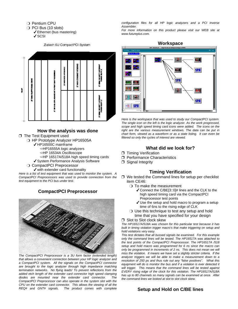
TRDY#
This is TRDY# and the clock. Note that TRDY# is pulled high by thesystem and then when driven drops to a slightly lower voltage level.
Summaryr Our Case Study system performed well!
m Better than the PC systems we’ve examined inthe past
r All PCI designers regardless of application can takeadvantage of the PCI Compliance Checklist
r The PCI designer must go well beyond theCompliance Checklist to achieve a fully compliantPCI design
This presentation has taken a brief look at how the industry isapproaching PCI test through the PCI Compliance Test Program. ACompactPCI system was used as a case study for a few compliancemeasurements. Our case study system performed well. No violationswere found. PCI has continually improved and the problems thatengineers are finding are migrating away from the simple protocol anddesign errors and migrating to the more complicated system andelectrical issues.It is estimated that PCI is currently being used or will soon be used byevery major computer manufacturer in the world. In order to ensure itssuccess proper testing is being promoted by the PCI industry.
Additional Resources (cont)
r Preprocessorsm Pentiumm PowerPCm ISA Busm USBm VMEm PMC-PCI Mezzaninem CardBus
r Software Debugm HP’s Software Analyzer
The Pentium and PowerPC Preprocessors along with the HP SoftwareAnalyzer are available from Hewlett-Packard Company.
The PCI, USB, PMC, VME, ISA, CardBus and the PCI PreprocessorPlus are available from FuturePlus Systems (719-380-7321 orwww.futureplus.com).
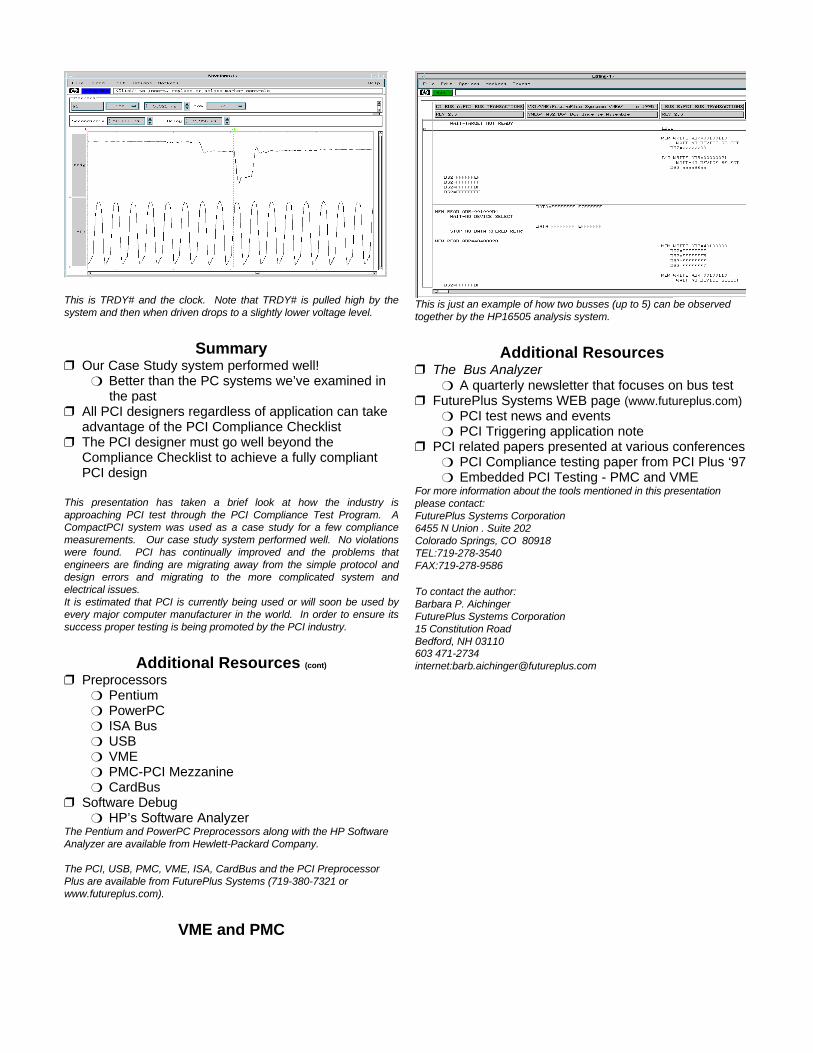
VME and PMC
This is just an example of how two busses (up to 5) can be observedtogether by the HP16505 analysis system.
Additional Resourcesr The Bus Analyzer
m A quarterly newsletter that focuses on bus testr FuturePlus Systems WEB page (www.futureplus.com)
m PCI test news and eventsm PCI Triggering application note
r PCI related papers presented at various conferencesm PCI Compliance testing paper from PCI Plus ‘97m Embedded PCI Testing - PMC and VME
For more information about the tools mentioned in this presentationplease contact:FuturePlus Systems Corporation6455 N Union . Suite 202Colorado Springs, CO 80918TEL:719-278-3540FAX:719-278-9586
To contact the author:Barbara P. AichingerFuturePlus Systems Corporation15 Constitution RoadBedford, NH 03110603 471-2734 internet:[email protected]