Embed Size (px)
Citation preview

1
Tech
nic
alS
pec
ific
atio
ns
Tro
ub
lesh
oo
tin
gP
rod
uct
Ou
tlin
eU
se w
ith
aM
acin
tosh
Win
do
ws
95/
98/N
TS
afet
yS
tan
dar
ds
PCD-47 User’s Manual
Microtech PCD-47
SCSI PC Card Reader/Writer
PCD-47B — internal for various systemsPCD-47-MAC — external for MacintoshPCD-47-PC — external for PC Compatibles
○
○
○
○
○
○
○
○
○
○
○
○
○
○
○
○
○
○
○
○
○
○
○
○
○
○
○
○
○
○
○
○
○
○
○
○
○
○
○
○
○
○
○
○
○ ○ ○ ○ ○ ○ ○ ○ ○ ○ ○ ○ ○ ○ ○ ○ ○ ○ ○ ○ ○ ○ ○ ○ ○ ○ ○ ○ ○ ○
ver 1.1

2
* Support of the PCD-47 series for any Unix system on an OEM basis must be arranged undera separate contract.
• MS-DOS is the registered trademark of Microsoft.• Apple and Macintosh are the registered trademarks of Apple Computer, Inc.• IBM PC/AT is the trademark of International Business Machines Corporation.• EZ-SCSI is the trademark of Adaptec, Inc.• Photoshop is the registered trade mark of Adobe Systems, Inc.• Other company names and product names are the trademarks and registered trademarks of
their respective companies.
© Copyright 2000 Microtech International, Inc. All rights reserved. MP00621
Preface
Thank you for purchasing the Microtech PCD-47. The PCD-47 can be connected to various makes of personal computersto read and write digital film cards. The data recorded on adigital film card with a digital camera can thus be directly readinto a personal computer. Please read these instructionscarefully before installation and use.
The features of this product include:
❏ SCSI interface for high speed data transfer to your computer.❏ Can be connected to Macintosh, IBM PC/AT compatible
computers, running Dos, Windows 3.x, Windows 98 andWindows NT.
❏ Can be used with Solaris, Sun Sparc, Sun Ultra Sparc, DigitalUnix, VMS, AIX, HP and Linux.*
❏ One type III slot, one CompactFlash slot, and one SmartMedia(SSFDC) slot.Of the standard PCMCIA/JEIDA cards, ATA cards, CompactFlash,and SmartMedia (both 3.3V and 5V, supports up to 128MB ofSmartMedia) may be used.

3
Tech
nic
alS
pec
ific
atio
ns
Tro
ub
lesh
oo
tin
gP
rod
uct
Ou
tlin
eU
se w
ith
aM
acin
tosh
Win
do
ws
95/
98/N
TS
afet
yS
tan
dar
ds
Table of Contents
Preface .......................................................................................................... 2FCC radio frequency interference warning .................................................. 5Precautions ................................................................................................... 6Safety Precautions and handling .................................................................. 71. Product outline ........................................................................................ 8
Using with Macintosh .................................................................................. 8Using with Windows .................................................................................... 8Using with Unix Systems ............................................................................. 92. Accessories ............................................................................................. 10
3. Identifying the parts .............................................................................. 11
4. Making connections with a computer .................................................. 13
Use without other SCSI devices ................................................................. 13Termination ................................................................................................ 14Other Jumper Pins ....................................................................................... 14Use with other SCSI devices ...................................................................... 15SCSI ID Settings Explained ................................................................................................... 15
Setting SCSI ID (external) .......................................................................... 16A SCSI hint for Mac Users .......................................................................... 16SCSI ID Table ............................................................................................. 17Setting SCSI ID (internal). .......................................................................... 17SCSI ID Settings for Windows Computers ................................................. 18Turning on the power ................................................................................. 185. Installation (Windows) .......................................................................... 19
SCSI Card Installation ................................................................................ 19Windows 95/98 and Windows NT Users .................................................... 19External Reader Installation ...................................................................... 20Internal Reader Installation ........................................................................ 206. Basic operations (Windows) ................................................................. 20
Inserting the PC card .................................................................................. 20Removing the PC card ............................................................................... 237. Installation (Macintosh) ........................................................................ 23
Functions of the Macintosh Driver ............................................................ 238. Basic Operations (Macintosh) .............................................................. 23
................................................................................................................................................... 24
4
Table of Contents Continued
When the lock indicator is lit ..................................................................... 2410. Troubleshooting ................................................................................... 26
Windows Troubleshooting ...........................................................................26Macintosh Troubleshooting .........................................................................2711. Specifications .........................................................................................28
Dimensions ..................................................................................................29SCSI Command Set .....................................................................................31Safety Standards ..........................................................................................32
Index ............................................................................................................33

5
Tech
nic
alS
pec
ific
atio
ns
Tro
ub
lesh
oo
tin
gP
rod
uct
Ou
tlin
eU
se w
ith
aM
acin
tosh
Win
do
ws
95/
98/N
TS
afet
yS
tan
dar
ds
FCC radio frequency interference warning
This equipment generates and uses radio frequencies, and if notinstalled and used in strict accordance with the manufacturer’sinstructions, can cause interference to radio and television reception.This equipment has been certified and found to comply with the limitsfor a Class B computing device in accordance with the specificationsin Subpart J of Part 15 of the FCC rules, which are designed toprovide reasonable protection against such interference in a commer-cial installation.However, there is no guarantee that interference will not occur in aparticular installation. If this equipment does cause interference toradio or television reception, which can be determined by turning theequipment off and on, the user is encouraged to try to correct theinterference by one or more of the following measures:
1. Re-orient the receiving antenna.2. Re-orient the computer with respect to the receiver.3. Move the computer further away from the receiver.4. Plug the computer or receiver into a different outlet so
computer and receiver are on different branch power circuits.5. Ensure that card mounting screws, attachment connector
screws, and ground wires are tightly secured.
If necessary, the user should consult with the dealer or an experi-enced radio/television technician for additional suggestions. The usermight find the following booklet helpful, prepared by the FederalCommunications Commission: How to Identify and Resolve Radio TVInterference Problems. It is available from the U. S. GovernmentPrinting Office, Washington, DC 20492, Stock No. 004-000-00345-4(FCC Part No. 15.838b)
* Notice for customers in Canada. This apparatus complies with theClass B limits for radio noise emissions set out in Radio InterferenceRegulations.

6
Precautions
� Power sourceThe PCD-47 uses a standard domestic household power cord.The PCD-47-MAC and PCD-47-PC operate at voltages between100V to 240V. The PCD-47B operates using the computer’selectrical power.
� Power cord - Do not bend the power cord excessively or place heavy objects on
it. - Damage to the cord may cause fire or electric shock. - Do not unplug the cord by pulling on it. - Do not plug or unplug with wet hands. - Unplug from the outlet when you are not using the unit for long
periods of time. - Plug the power cord directly into a wall outlet whenever possible.
Use of extension cords and power dividers can cause malfunctions. - Do not use outlets that have other large electrical appliances, such
as air conditioners and copy machines plugged in them.
� To prevent electric shockNever remove the cabinet of this unit. Some components insideoperate at high voltages and can cause severe electric shock iftouched.
� Keeping objects and materials out of the unitMake sure that no liquid is spilled or leaks into this unit and that nometal or inflammable objects fall inside since this can cause fire,shock, malfunctioning or accidents.
� In case of accident or malfunctionIf the unit makes unusual noises or begins smoking, or if a foreignobject gets inside the unit, unplug the power cord from the outletand contact the dealer from which you purchased the unit.

7
Tech
nic
alS
pec
ific
atio
ns
Tro
ub
lesh
oo
tin
gP
rod
uct
Ou
tlin
eU
se w
ith
aM
acin
tosh
Win
do
ws
95/
98/N
TS
afet
yS
tan
dar
ds
Safety Precautions and handling
� Proper places for use and storage - This unit is to be used at temperatures between +5°C and +40°C and at
relative humidities between 20% and 80%(with no condensation). - Do not use or store the unit in an excessively hot or cold place. - Do not use or store the unit in a dusty place or in direct sunlight. - Do not use or store the unit in a place subject to excessive vibration or in
an unstable place to prevent possible failures. - Do not place the unit close to a system which generates strong magnetic
fields (motor, transformer, television, loudspeaker, magnet etc.) toprevent malfunction.
- Do not close vents that may cause internal temperature to rise. - Do not stack the units. - Do not use in an enclosed (unventilated) area.
� Precautions for connectionWhen connecting this unit to a personal computer or any other equip-ment, always first turn off the main power of the equipment to beconnected.
� Precautions for transportation - Disconnect cables and remove any PC cards before transporting the unit. - Use the cardboard box in which the unit was initially packed. - This is a precision device. Do not subject to excessive shock or vibra-
tion.
� Maintenance of the cabinet - Do not use thinner, benzene, insecticide and other volatile substances to
clean the cabinet as this may cause deterioration and delamination ofthe paint.
- Clean the cabinet and front panel with a soft cloth. Remove severe dirtwith a soft cloth moistened with a small amount of neutral detergentdiluted with water. Wipe dry after cleaning.
- Disconnect the power plug from the receptacle before performing anymaintenance on the unit.
8
1. Product outlineThis PC card drive is designed to be connected to a personal com-puter to read and write PC cards (ATA type II, CompactFlash,SmartMedia, and PCMCIA hard disks). A SCSI interface is used toenable the device to be connected to a Macintosh, IBM PC/ATcompatible running Dos, Windows 95/NT/98, Sun Sparc and Sun UltraSparc, or other personal computers.
Using with Macintosh*
Connect the card drive to the SCSI port, the standard Macintoshhard disk interface. Some more recent Macintosh models (ex: G3,G4) may require the addition of a PCI SCSI board. Microtech recom-mends Adaptec SCSI boards. Use of the PCD-47 with a Macintoshrequires the use of Macintosh mounting software to mount removablemedia such as PC cards, CompactFlash, SmartMedia, and PCMCIAhard disks. Microtech includes Software Architects DOS Mounter SEwith the Macintosh version of the PCD-47 (part no: PCD-47-MAC).For owners of other versions of the PCD-47, this software can bepurchased as an option through Microtech along with the reader, ormay be purchased from a separate vendor. The software may alsobe purchased and downloaded online at:
http://www.softarch.com/go/online.html
Using with Windows*
If you do not already have a SCSI board installed, follow the installa-tion instructions that come with your SCSI board. The manufacturerrecommends Adaptec SCSI boards. For Dos, Windows 3.x Windows95/NT/98, simply connect the PC Card reader to the SCSI board, oranother SCSI device, turn on the PC Card reader’s power and rebootthe computer. Your PC card reader will appear as a drive letter under“My Computer”. You may now insert PC cards and access them asyou would a hard drive or floppy disk drive.
* The PCD-47 requires three SCSI IDs.

9
Tech
nic
alS
pec
ific
atio
ns
Tro
ub
lesh
oo
tin
gP
rod
uct
Ou
tlin
eU
se w
ith
aM
acin
tosh
Win
do
ws
95/
98/N
TS
afet
yS
tan
dar
ds
Using with Unix Systems‡
This page should explain the basic features of Unix, and pointers toUnix informaiton, and mounting of Dos file systems.
Unix systems use a disk format that is different from Windowsmachines, and memory cards used in digital cameras. Most Unixsystems require a special mounting procedure such as the following toaccess DOS formatted media:
mount - dev/scsi/dev000001 /dev/pccard
‡Note: Tech support for Unix systems is only available under
special OEM contract and license.
Each Unix system may vary slightly in the above mounting procedure,and it is assumed that the User understands how to use his/herparticular system. For further assistance mounting DOS partitions onyour particular system, type “man mount” at the unix shell prompt formore information on mounting. An example is shown below:
10
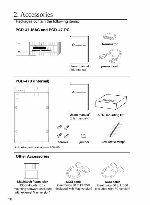
2. Accessories Packages contain the following items:
Macintosh floppy diskDOS Mounter SE -
mounting software (includedwith external Mac version)
SCSI cableCentronics 50 to HD50
(included with PC version)
Users manual*(this manual)
.........................
.........................
Other Accessories
SCSI cableCentronics 50 to DB25M
(included with Mac version)
screws jumper
PCD-47-MAC and PCD-47-PC
PCD-47B (Internal)
I N T E R N A T I O N A L, I N C.
power cord
terminator
Anti-static strap*
Users manual(this manual)
* Included only with retail version of PCD-47B.
5.25” mounting kit*
Mounting Kit

11
Tech
nic
alS
pec
ific
atio
ns
Tro
ub
lesh
oo
tin
gP
rod
uct
Ou
tlin
eU
se w
ith
aM
acin
tosh
Win
do
ws
95/
98/N
TS
afet
yS
tan
dar
ds
(1) Power Indicator LampThis indicator lights when power to the reader is turned “ON”.
(2) Access Indicator Lamp/Lock Indicator LampThese indicator lamps shows the access state of each slot. Itlights during read or write operations (green). (With a Macintoshcomputer, this indicator flashes even when no card is inserted.)These indicators light when the inserted card is locked (orange).Do not remove the locked card from the drive.
(3) Eject ButtonsPushing this button ejects the PC card.
(4) Card SlotsType I, II, and III PC cards may be inserted, as well asSmartMedia and CompactFlash. Note that CompactFlash andSmartMedia have their own special slots.
5) Power ButtonThe power switch is only featured PCD-47 external models.Internal models are activated when the hostcomputer is poweredon.
3. Identifying the parts
This drive unit consists of the following parts:
FRONT PANEL
I N T E R N A T I O N A L, I N C.
21
4 3
2
5

12
(6) FanWhen this switch is "on", the fan is active.
(7) SCSI connectorSCSI cable is connected here.
(8) Power connectorFor external units, connect the power cord included in the packageto this connector. Make sure that the connector is connectedsecurely and properly. For internal units, connect to one of thecomputers internal power cords.
(9) SCSI ID SwitchUse this switch to set SCSI ID number. Do not to set the SCSI IDnumber to numbers already in use by the computer or otherperipheral devices.
(10) SCSI ID pinsUse this to set the SCSI ID number. (internal units only) Placejumpers to set ID number. See above illustration for details.
REAR PANEL
124
terminator}I
5
976
8
10
SCSI ID
................................................... . . .
8 7

13
Tech
nic
alS
pec
ific
atio
ns
Tro
ub
lesh
oo
tin
gP
rod
uct
Ou
tlin
eU
se w
ith
aM
acin
tosh
Win
do
ws
95/
98/N
TS
afet
yS
tan
dar
ds
4. Making connections with a computer
This drive unit connects to a computer through a SCSI cable. Thereare two types of connection depending on whether or not an additionalSCSI device is to be used. These two cases are discussed later inthis section.
Note: there are several physical forms of SCSI connector. The most common SCSIcable is included with external units. If you need a special SCSI cable, check theSCSI connector of the computer and SCSI device to be connected and procure aproper SCSI cable.For connection with an IBM PC/AT compatible computer, a SCSI board must havebeen previously mounted in the computer. Consult the documentation that came withthe SCSI board for installation instructions.
CAUTION: Turn off the power to the computer and SCSI device(s) before making theconnections.
Use without other SCSI devices
Plug one end of the SCSI cable into the SCSI connector at the rear ofthe computer and the other into the SCSI connector at the rear of thisdrive unit. Securely plug the cable end into the connector then fix itwith clamps or screws.
NOTE: For external units, use a high-impedance (100-ohm) type SCSI cable. Becareful not to use printer cables, as they can look like SCSI cables, but will causemalfunctions, and possible loss of data.
.........................
.........................
termination jumper
terminator

14
Termination
When this unit is the only device on the SCSI chain, or the last deviceon the SCSI chain, it must be terminated.External: attach the terminator to the SCSI connector not being used.Internal: Default is terminated. When the termination pin jumper is“off”, the unit is terminated. When the terminator pin jumper is “on”, theunit is not terminated.
(1) External units come with an external terminator as shown in theabove diagram. Internal devices come with termination pins, asshown in the right hand side of the above diagram.
Other Jumper Pins
(1) Jumper off: all three slots are active. Jumper on: only SmartMediaand CompactFlash are active (type III slot is disabled).(2-3) Vendor unique usage(4) Jumper on: firmware rewrite mode. Jumper off: standard use.firmware cannot be rewritten with jumper off. Jumper should remain offwhen the unit is in “regular use”. Unit cannot function normally withthis jumper on. Jumper is only to be “on” when rewritting firmware.
124
terminator}SCSIID
1 2 3 4
.........................
.........................
termination jumper
terminator

15
Tech
nic
alS
pec
ific
atio
ns
Tro
ub
lesh
oo
tin
gP
rod
uct
Ou
tlin
eU
se w
ith
aM
acin
tosh
Win
do
ws
95/
98/N
TS
afet
yS
tan
dar
ds
Use with other SCSI devices
Since the SCSI standard supports connection to one computer and upto seven SCSI devices (including SCSI devices built into the com-puter), you can use several card drives in a series or connect thePCD-47 drive to other SCSI device(s) (the PCD-47 uses threeconsequtive SCSI IDs).Plug one end of the SCSI cable to the SCSI connector, and the otherinto the SCSI connector at the rear of this drive unit. Securely plugthe cable end into the connector. The order of the SCSI devices to beconnected can be changed.
SCSI ID Settings ExplainedThe SCSI ID is a unique number assigned to each SCSI device.Therefore, two devices must not have the same ID number. The SCSIID is independent of the order of physical device connection. Ingeneral, SCSI ID=7 is assigned to the computer and ID numbers 0 to6 are available for other SCSI devices. Note that SCSI IDs may havebeen previously assigned to a disk drive, CD-ROM drive, or otherbuilt-in devices in the computer. To obtain this information, refer to therelated computer and SCSI device manuals. Take care not to use thesame SCSI ID number more than once.
* The PCD-47 uses 3 SCSI IDs. See “Setting the SCSI ID” for a tableexplaining the SCSI IDs.
................................................... . . .
................................................... . . .
................................................... . . .
other SCSI devices
PCD 47
PCD47

16
NOTE: Change the SCSI ID number after turning off the power to this drive unit andcomputer. The new number will not become effective while power is still turned on.
Setting SCSI ID (external)
For external units, you can change the value on the ID number displaywindow by turning the SCSI ID switch. If you encounter overlappingSCSI IDs, reassign the ID numbers. The initial default value “4” isassigned to all drive units in the factory before shipment. For internalunits, set the SCSI ID with SCSI ID jumpers as shown in the diagram.In all cases, two consecutive SCSI ID numbers must be available.
A SCSI hint for Mac Users
SCSI ID=0 is assigned to the built-in hard disk drive, SCSI ID=3 tothe built-in CD-ROM drive, and SCSI ID=7 to the computer beforeshipment. Therefore, SCSI ID=1, SCSI ID 2, SCSI ID=4, SCSI ID=5,and SCSI ID=6 are available for this drive unit.
It will therefore be necessary to pay close attention to the SCSI IDson your Macintosh, as the PCD-47 requires three SCSI IDs. See“Setting SCSI IDs” for an explanation of SCSI ID usage.
NOTE: SCSI ID=3 is available when the Macintosh computer has no built-in CD-ROM drive. For an external CD-ROM drive, SCSI IDs other than “3” may beassigned. In either case, it is imperative to check the SCSI ID for all SCSI devices.Also, note that the SCSI ID for the built-in hard disk drive and the computer cannotbe changed.
4
4
4

17
Tech
nic
alS
pec
ific
atio
ns
Tro
ub
lesh
oo
tin
gP
rod
uct
Ou
tlin
eU
se w
ith
aM
acin
tosh
Win
do
ws
95/
98/N
TS
afet
yS
tan
dar
ds
To set the SCSI ID on internal units, set the three jumper pins asshown in the diagram. The default SCSI ID is 4 (5 and 6).
3 3 4 5
1 1 2 4
2 2 3 4
0 0 1 2
4 4 5 6
5 5 6 -
6 6 - -
ID setting PCMCIA SmartMedia CompactFlash
SCSI ID Table
Setting SCSI ID (internal).
terminator
1 2 3 4 5 6
SCSI ID pins (first 3 rows)
SCSI ID pins (first 3 rows)
0

18
SCSI ID Settings for Windows Computers
SCSI IDs “0” and “1” may have been previously assigned to the built-inhard disk drive. Therefore, the value “2” is recommended as the firstSCSI ID for this drive unit. For details, consult the manuals for yourSCSI board.
To connect the power cable, plug the end of the power cord included inthe package into the power connector on the rear of this drive unit,then plug the other end into the AC outlet (or the computers internalpower connector for internal units). The cord should be firmly andsecurely connected and should be grounded before use.
Turning on the power
For external drives, turn on the power for this drive unit, then turn onthe computer. For internal drives, after installation is complete, replacethe computer case and securely fasten the case. Replace power cordsand restart the computer.
Windows users may simply restart the computer and the unit willappear under “My Computer” “as three drive letters. The drive letterswill vary depending on the configuration of the particular computer andthe number of devices. For further instructions see the followingsection “Basic Operations (Windows)”.
Mactintosh Users should refer to the section “Using with a MacintoshComputer”. When the computer is ready, install the software driver inaccordance with Section 6 “Using with a Macintosh computer” andSection 7 “Using with an IBM PC/AT compatible computer”.

19
Tech
nic
alS
pec
ific
atio
ns
Tro
ub
lesh
oo
tin
gP
rod
uct
Ou
tlin
eU
se w
ith
aM
acin
tosh
Win
do
ws
95/
98/N
TS
afet
yS
tan
dar
ds
5. Installation (Windows)Applicable enviromentThe PCD-47 can be installed in the following environments:- SCSI board Adaptec SCSI board (recommended)- Software driver Adaptec EZ-SCSI (recommended)- Operating system MS-DOS 5.0 or higher- Windows Ver. 3.x, Win 95/98, Windows NT
SCSI Card Installation
Follow these directions if you do not yet have a SCSI interface cardinstalled. Although our reader should work with nearly one hundredpercent of the SCSI interface cards on the market, we highly recom-mend using one of the Adaptec series. The following instructions werewritten for Adaptec cards and may or may not work for other cardtypes. Refer to the SCSI card manual for details. Technical questionsconcerning other SCSI cards should be directed to the SCSI cardmanufacturer, not the PC Card reader manufacturer.
1. Shut down the system, and turn off the computer.2. Unplug all cables connecting to the computer, and remove the case.3. Install the Adaptec SCSI card into an empty expansion slot.4. Make sure all connections are secure and re-assemble the computer along
with all the cables.
Windows 95/98 and Windows NT Users
5. Simply power on the machine, and boot to Windows.6. If windows doesn’t autodetect your SCSI card, then enter the control
panel from the Start->Setup->Control Panel menu, and double-click on“add new hardware”.
7. Select the “Auto-detect hardware” option and wait for completion.8. Windows NT users may need to consult the Windows NT manual for
hardware installation.

20
External Reader Installation
1. Follow the directions above to set up your SCSI interface cardunless you have already done so previously.
2. Close all applications, exit Windows to return to the commandprompt (or shutdown Windows 95), and turn off the system.
3. Connect the reader to the SCSI bus.4. Set the SCSI ID number in the back of the device to a number
between 0 and 4. Be careful not to set it to a number already in useby another SCSI device. If this is your only SCSI device includinginternal SCSI hard disks, then any number will work.
5. Turn on the power to the reader and any other needed externaldevices.
6. Turn on the computer and boot to Windows.7. Insert the PC card to be accessed.
NOTE: Make sure everything is connected properly, the terminator is in the correctposition, and the SCSI ID is set to a number not currently in use by the system.
Internal Reader Installation
1. Follow the directions above to set up your SCSI interface cardunless you have already done so previously.
2. Close all applications, exit Windows to return to the commandprompt (or shutdown Windows), and turn off the system.
3. Set the SCSI ID number as shown later in this manual. Make surethat the SCSI ID number is not already in use by another SCSIdevice.
4. Connect the reader to the inside of your computer.5. Turn on the computer and boot to Windows.6. Insert the PC card to be accessed.

21
Tech
nic
alS
pec
ific
atio
ns
Tro
ub
lesh
oo
tin
gP
rod
uct
Ou
tlin
eU
se w
ith
aM
acin
tosh
Win
do
ws
95/
98/N
TS
afet
yS
tan
dar
ds
6. Basic operations (Windows)
This section describes the operation relating to PC cards. For installa-tion, refer to Section 6 “Using with a Macintosh computer” and Section7 “Using with a Windows computer”.
Inserting the PC card
1. Insert the PC card into the slot in the correct direction as shown in thefigure below, then push the card in all the way until the eject buttonpops out.
2. Be careful not to insert the PC card in the wrong direction. If it is forcedin, the slot or PC card may be damaged or data on the card may be lost.When inserting SmartMedia cards be sure to insert the SmartMedia withthe gold contacts facing up. To insert CompactFlash cards, gently pushthe card in all the way until the card is locked in place. The card willslide in on the molded rails and a slight amount of resistance will be feltas the connectors make contact. This is normal.
Note for Mac users: With a Macintosh computer, the lock indicatorlights first and then the PC card icon appears on the monitor. This isthe “mounted” state, which enables read and write operations for thePC card. The time required between card insertion and mountingdepends on the PC card. Usually, the PC card can be mountedwithin several seconds.
I N T E R N A T I O N A L, I N C.
I N T E R N A T I O N A L, I N C.
I N T E R N A T I O N A L, I N C.
CompactFlash
SmartMedia
PC card

22
4. When the PC card is not formatted, the following box appears. Clickingon the “Initialize” button causes the PC card to be formatted (initial-ized).
NOTE: When the PC card is used for a digital camera, the formatting should beperformed on the camera.
5. For Windows computers, the lock indicator does not usually light evenafter a PC card is inserted. For a Macintosh computer, wait for severalseconds to access the PC card.
3. Using a Windows computer, three icons will appear under “My Com-puter” as a removable hard drive (a drive letter will also be assigned).Double click on an icon to open the drive. If media is not inserted whendouble clicking the icon, the message “Device not ready” will appear.Insert card and click “OK”.
Removing the PC card
Make sure that the access indicator and lock indicator are not lit, andthat the card is not being accessed, then press the eject button torelease the PC card. To remove the SmartMedia from the reader,press firmly but gently on the card, then release. The SmartMedia willpop out of the reader.

23
Tech
nic
alS
pec
ific
atio
ns
Tro
ub
lesh
oo
tin
gP
rod
uct
Ou
tlin
eU
se w
ith
aM
acin
tosh
Win
do
ws
95/
98/N
TS
afet
yS
tan
dar
ds
7. Installation (Macintosh)
Macintosh driver software is required to automatically mount digitalfilm cards with the PCD-47 in a Macintosh environment. Microtechincludes the driver software with the external Macintosh version ofthe PCD-47 only (part no. PCD-47-MAC). For owners of otherversions of the PCD-47(ex: part no. PCD-47B, or PCD-47-PC), thissoftware can be purchased as an option through Microtech.
Functions of the Macintosh Driver
The Macintosh software driver mounts removable media such asdigital film cards (ATA cards, SmartMedia and CompactFlash) on aMacintosh computer. This sofware prodives the following functions:
- Automatically mounts the Macintosh formatted or DOS-formatted PCcards or other removable media (most digital cameras use DOS formatson their cards.).
NOTE: The DOS format is used by IBM PC/AT compatible computers and most digitalcameras. The files stored on a DOS-formatted PC card are DOS files.
For instructions on installing the optional Macintosh driver software,please read the instruction manual that came with the software.
The access indicator is litIn this case, the data is being read or written. Wait until the operationsare complete; then remove the card. Removing the card during accessoperations will cause the data to be lost.
8. Basic Operations (Macintosh)

24
9. Firmware Upgrades
From time to time firmware upgrades may be made available as newcomputer systems, smartmedia cards, and digital applicationsbecome available on the market.
If firmware upgrades are made available, the necessary program fileswill be made available, along with the updated instructions, athttp://www.microtechint.com/firmware/.
SCSI jumper must be“ON” to upgrade firmware.Jumper must be removedbefore unit can be usednormally again.

25
Tech
nic
alS
pec
ific
atio
ns
Tro
ub
lesh
oo
tin
gP
rod
uct
Ou
tlin
eU
se w
ith
aM
acin
tosh
Win
do
ws
95/
98/N
TS
afet
yS
tan
dar
dsWhen the lock indicator is lit
For Macintosh computers, the lock indicator lights when the PC cardis mounted. Dragging the PC card icon and dropping it onto the trashicon ejects the PC card, deletes the PC card icon and turns off thelock indicator on this drive unit.
Do not remove the mounted PC card. If removed, the followingmessage appears on the screen. Put the card back into the slot whereit was.
NOTE: For Macintosh computers, the access indicator may flash on and off evenafter the eject operation. In this case, you can remove the PC card.
NOTE: Do not select the “Eject Disk” command from the “Special” menu to removethe card.
For IBM PC/AT compatible computers, the lock indicator does notlight in normal cases. You can remove the PC card when the accessindicator is not lit.
NOTE: When you lock the PC card with the EZ-SCSI utility, the lock indicator lights.In this case, unlock the PC card with the same utility, then make sure that the lockindicator goes off before removing the PC card.
Do not use.
26
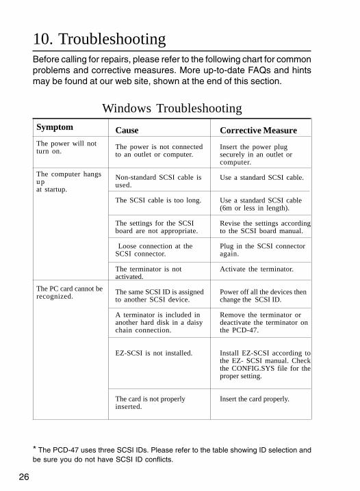
10. TroubleshootingBefore calling for repairs, please refer to the following chart for commonproblems and corrective measures. More up-to-date FAQs and hintsmay be found at our web site, shown at the end of this section.
* The PCD-47 uses three SCSI IDs. Please refer to the table showing ID selection andbe sure you do not have SCSI ID conflicts.
Symptom
The power will notturn on.
The computer hangsupat startup.
The PC card cannot berecognized.
Corrective Measure
Insert the power plugsecurely in an outlet orcomputer.
Use a standard SCSI cable.
Use a standard SCSI cable(6m or less in length).
Revise the settings accordingto the SCSI board manual.
Plug in the SCSI connectoragain.
Activate the terminator.
Power off all the devices thenchange the SCSI ID.
Remove the terminator ordeactivate the terminator onthe PCD-47.
Install EZ-SCSI according tothe EZ- SCSI manual. Checkthe CONFIG.SYS file for theproper setting.
Insert the card properly.
Cause
The power is not connectedto an outlet or computer.
Non-standard SCSI cable isused.
The SCSI cable is too long.
The settings for the SCSIboard are not appropriate.
Loose connection at theSCSI connector.
The terminator is notactivated.
The same SCSI ID is assignedto another SCSI device.
A terminator is included inanother hard disk in a daisychain connection.
EZ-SCSI is not installed.
The card is not properlyinserted.
Windows Troubleshooting
27
Tech
nic
alS
pec
ific
atio
ns
Tro
ub
lesh
oo
tin
gP
rod
uct
Ou
tlin
eU
se w
ith
aM
acin
tosh
Win
do
ws
95/
98/N
TS
afet
yS
tan
dar
ds
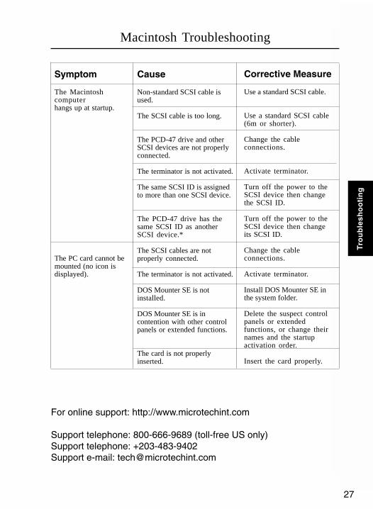
For online support: http://www.microtechint.com
Support telephone: 800-666-9689 (toll-free US only)Support telephone: +203-483-9402Support e-mail: [email protected]
Cause
Non-standard SCSI cable isused.
The SCSI cable is too long.
The PCD-47 drive and otherSCSI devices are not properlyconnected.
The terminator is not activated.
The same SCSI ID is assignedto more than one SCSI device.
The PCD-47 drive has thesame SCSI ID as anotherSCSI device.*
The SCSI cables are notproperly connected.
The terminator is not activated.
DOS Mounter SE is notinstalled.
DOS Mounter SE is incontention with other controlpanels or extended functions.
The card is not properlyinserted.
Symptom
The Macintoshcomputerhangs up at startup.
The PC card cannot bemounted (no icon isdisplayed).
Corrective Measure
Use a standard SCSI cable.
Use a standard SCSI cable(6m or shorter).
Change the cableconnections.
Activate terminator.
Turn off the power to theSCSI device then changethe SCSI ID.
Turn off the power to theSCSI device then changeits SCSI ID.
Change the cableconnections.
Activate terminator.
Install DOS Mounter SE inthe system folder.
Delete the suspect controlpanels or extendedfunctions, or change theirnames and the startupactivation order.
Insert the card properly.
Macintosh Troubleshooting

28
11. SpecificationsCard type: ATA cards, PCMCIA hard disks
CompactFlash SmartMedia
Card slots: one Type I/II/III, one SmartMedia one CompactFlash
Host interface: SCSI-II
SCSI connector: External: 50 pin Centronics Internal: 50 pin header
Transfer rate: 4MB/sec (asynchronus transfer)
Power requirements: External: AC 100V to 240V, 50/60 Hz Internal: 5v/12v DC (Standard PC Connector)
Power consumption: 0.2A (internal)
External Dimensions (W x D x H): 169 x 211 x 55 mm (2.5x7x8 inches)
Internal Dimensions (W x D x H): 101.6 x 25.4 x 150 mm (4x1x6 inches)
Weight: External: Approx. 4.3lbs/150 grams Internal: Approx. 10.2oz/150 grams
Ambient conditions for use: Temperature: +5°C to +40°C
Humidity: 20% to 80% (with no condensation)
Agency Approvals: FCC, CE

29
Tech
nic
alS
pec
ific
atio
ns
Tro
ub
lesh
oo
tin
gP
rod
uct
Ou
tlin
eU
se w
ith
aM
acin
tosh
Win
do
ws
95/
98/N
TS
afet
yS
tan
dar
dsDimensions PCD-47B
Top view
Front view
Side view
165.4 mm
101.
6 m
m
25.4
mm
101.6 mm
147.8 mm
25.4
mm

30
Dimensions PCD-47 External
I N T E R N A T I O N A L, I N C.
169 mm
211 mm
55 mm
31
Tech
nic
alS
pec
ific
atio
ns
Tro
ub
lesh
oo
tin
gP
rod
uct
Ou
tlin
eU
se w
ith
aM
acin
tosh
Win
do
ws
95/
98/N
TS
afet
yS
tan
dar
ds
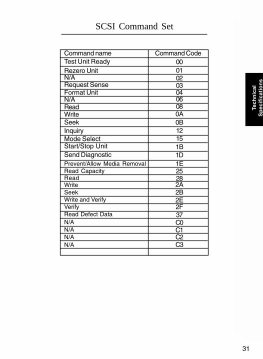
SCSI Command Set
Test Unit ReadyCommand CodeCommand name
000102
Rezero UnitN/A
03Request SenseFormat UnitN/AReadWriteSeekInquiryMode SelectStart/Stop UnitSend DiagnosticPrevent/Allow Media RemovalRead CapacityReadWriteSeekWrite and VerifyVerifyRead Defect DataN/A
0406080A0B12151B1D1E25282A2B2E2F37C0C1C2C3
N/AN/AN/A

32
Safety Standards
For more information on safety standards, please refer to the Pre-cautions section on page 6, and the Safety Precaution and Handlingsection on page 7.
33
Tech
nic
alS
pec
ific
atio
ns
Tro
ub
lesh
oo
tin
gP
rod
uct
Ou
tlin
eU
se w
ith
aM
acin
tosh
Win
do
ws
95/
98/N
TS
afet
yS
tan
dar
ds
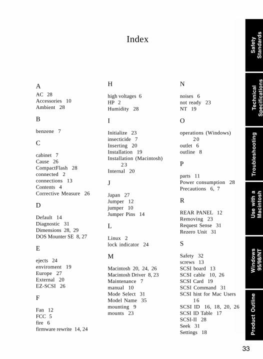
AAC 28Accessories 10Ambient 28
B
benzene 7
C
cabinet 7Cause 26CompactFlash 28connected 2connections 13Contents 4Corrective Measure 26
D
Default 14Diagnostic 31Dimensions 28, 29DOS Mounter SE 8, 27
E
ejects 24enviroment 19Europe 27External 20EZ-SCSI 26
F
Fan 12FCC 5fire 6firmware rewrite 14, 24
H
high voltages 6HP 2Humidity 28
I
Initialize 23insecticide 7Inserting 20Installation 19Installation (Macintosh)
23Internal 20
J
Japan 27Jumper 12jumper 10Jumper Pins 14
L
Linux 2lock indicator 24
M
Macintosh 20, 24, 26Macintosh Driver 8, 23Maintenance 7manual 10Mode Select 31Model Name 35mounting 9mounts 23
N
noises 6not ready 23NT 19
O
operations (Windows)20
outlet 6outline 8
P
parts 11Power consumption 28Precautions 6, 7
R
REAR PANEL 12Removing 23Request Sense 31Rezero Unit 31
S
Safety 32screws 13SCSI board 13SCSI cable 10, 26SCSI Card 19SCSI Command 31SCSI hint for Mac Users
16SCSI ID 16, 18, 20, 26SCSI ID Table 17SCSI-II 28Seek 31Settings 18
Index

34
severe electric shock 6shock 6SmartMedia
2, 20, 23, 28smoking 6softarch.com 8Specifications 28SSFDC 2support 27Symptom 26
T
temperature 7Termination 14terminato 26Test Unit Ready 31transportation 7Macintosh 27Troubleshooting 26Windows 26
U
Unix 9unix shell 9User Support 35
V
Verify 31voltages 6
W
Windows 95/98 19Write and Verify 31
Index

35
Tech
nic
alS
pec
ific
atio
ns
Tro
ub
lesh
oo
tin
gP
rod
uct
Ou
tlin
eU
se w
ith
aM
acin
tosh
Win
do
ws
95/
98/N
TS
afet
yS
tan
dar
ds
Microtech International, Inc.242 Branford Road,North Branford, CT. 06471-1303 USA
Tel: 800-626-4276 (toll-free US only)Tel: + 203-483-9402Fax: + 203-483-9792
www.microtechint.com


![[XLS] Web view1 99 2 99 3 99 4 99 5 99 6 98 7 98 8 98 9 98 10 98 11 98 12 98 13 98 14 98 15 98 16 98 17 98 18 98 19 98 20 98 21 98 22 98 23 97 24 97 25 97 26 97 27 97 28 97 29 97 30](https://img.dokumen.tips/doc/110x75/5b1e84727f8b9a116d8ba522/xls-web-view1-99-2-99-3-99-4-99-5-99-6-98-7-98-8-98-9-98-10-98-11-98-12-98-13.jpg)


![[XLS] · Web view118 118 45 45 88 118 118 128 128 128 128 98 98 12 12 12 98 98 98 88 98 58 128 128 98 98 98 98 98 98 98 98 12 12 98 98 98 98 12 98 98 98 58 12 98 98 98 98 98 98 98](https://img.dokumen.tips/doc/110x75/5b1aab787f8b9a1e258df5af/xls-web-view118-118-45-45-88-118-118-128-128-128-128-98-98-12-12-12-98-98.jpg)