Embed Size (px)
Citation preview

MAS 863
How To Make (almost) Anything
2009 10. 4.
PCB Design, Fabrication, Assembly
John Juhong Park
001.I add my learning on top of this class tutorial. Simply follow the order of
numbers.
PCB design
Eagle
ng.lbr
cad.py
pcb.cad
PCB fabrication
etching
ferric chloride, cupric chloride, ammonium/sodium persulfate
002.This is the PCB board that I used. It is placed on top of the base board
using double sided tape.
machining
0.010
1/64
1/32
003.This is a board right after cutting with 1/64 drill + with 1/32 drill
004. I took the board out from the machine.
cutting
printing
plating
sewing
PCB materials
rigid
FR4 (epoxy glass)
FR1 (phenolic paper)
flex
Kapton
#1 epoxy film, #1126 copper tape
high-frequency
teflon
glass
copper
0.5 oz: 17.5 um
1.0 oz: 35 um
2.0 oz: 70 um
board houses
AP Circuits, Advanced, Sierra
design rules
width/spacing (15, 5 mils)
layers
1, 1.5, 2, 4, N
solder mask, silk screen
vias
blind, buried
components
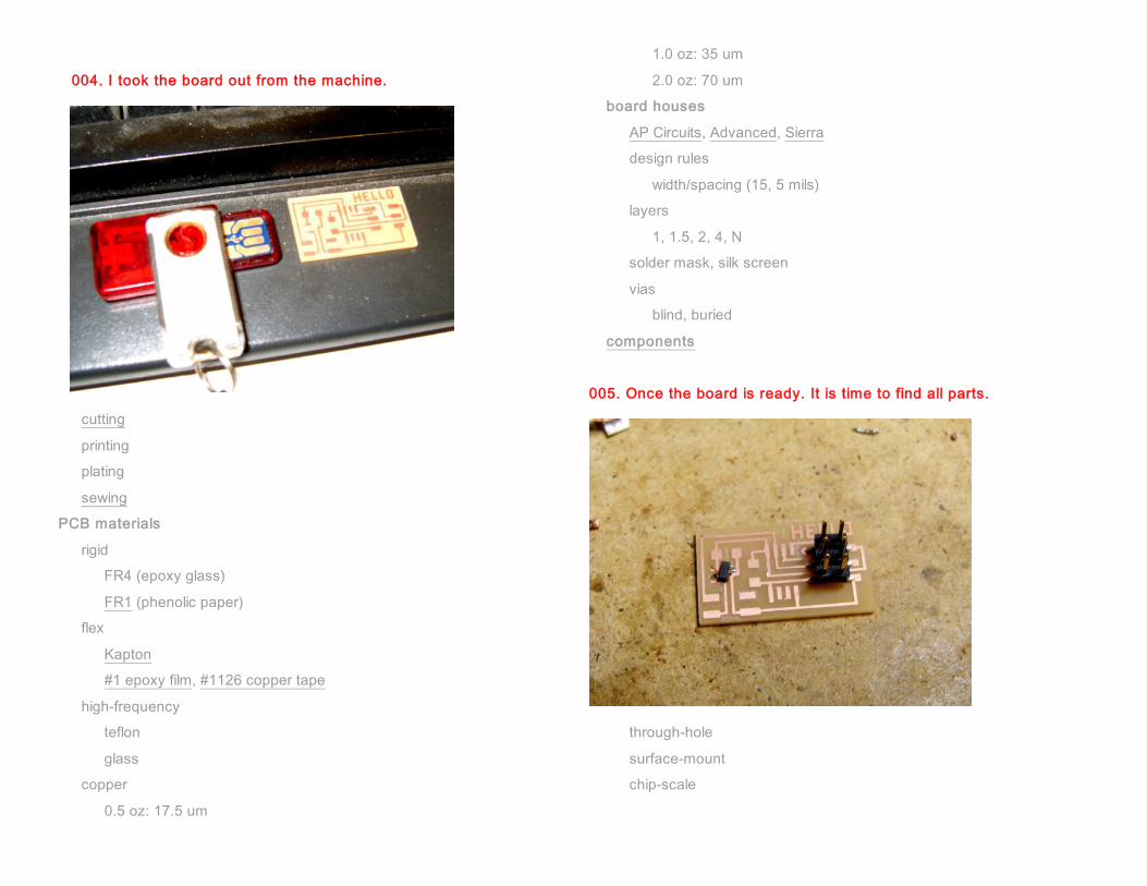
005. Once the board is ready. It is time to find all parts.
through-hole
surface-mount
chip-scale

assembly
solder
006. This is the board right after soldering.
Tip : One advice is to start soldering with smaller parts in center.
I wanted to practice soldering with safe parts like 4-pin and 6-pin
connectors. It is quite effective; I became quite comfortable after
soldering pin connectors and resistors. Then, it was suddenly
uncomfortable to solder small parts in center of the board. So
next time, I will start to solder from the center.
eutectic
wetting
flux
wire, paste, bar
ROHS
desoldering
reflow
wave
stuffing
tacking down parts
bottom to top, inside to outside
fumes
washing
pick-and-place
encapsulation
in-circuit programming
AVR Studio
avrdude
WinAVR
CrossPack
Dragon
avrdude -p t45 -P usb -c dragon_isp -U flash:w:file.hex
header plug <-> DB25M parallel (bsd) cable (wire side view):
avrdude -p t45 -c bsd -U flash:w:file.hex

007. Once the board is completed, it is time to start to make cables.
It was not easy for me to read these codes. So here are some tips
plug DB25
MISO (1) ------------- 10
V (2) ------------- no connection
-- SCK (3) --- cable --- 8
-- MOSI (4) - direction - 9
RESET (5) ------------- 7
GND (6) ------------- 18
008. The left side of the texts is 6-pin plug. As you noticed from
GND(6). And from “DB25”, the right side is 25-pin connector As you see below,
the BLUE cable of 6-pin connector goes into number 18 position of DB25
plug 1 4 3 5 6
DB25 13 12 11 10 9 8 7 6 5 4 3 2 1
DB25 25 24 23 22 21 20 19 18 17 16 15 14
This is DB25.
009. This part is optional and I just skipped it.
header plug <-> DB9F serial (dasa) cable (wire side view):
avrdude -p t45 -P /dev/ttyUSB0 -c dasa -U flash:w:file.hex
plug DB9
MISO (1) ------------- 8
V (2) ------------- no connection
-- SCK (3) --- cable --- 4
-- MOSI (4) - direction - 3
RESET (5) ------------- 7
GND (6) ------------- 5

plug 5 4 1 3 6
DCD Rx Tx DTR GND
DSR RTS CTS RI
DB9 1 2 3 4 5
DB9 6 7 8 9
serial programming voltage limiter: dasa.cad
connectors
IDC
header, plug
DB9, DB25
010. The next cable is connecting a 4-pin connector and a DB9.
RS232
serial header plug <-> DB9F cable (wire side view):
plug DB9
GND (1) ------------- 5
-- DTR (2) --- cable --- 4
-- Tx (3) - direction - 3
Rx (4) ------------- 2
011.The above image shows a 4-pin connector. The below is DB9.

012. There is also a DB9 connector with a simple slip connection. Unfortunately
they were all gone and I need to solder cables to
the other type of DB9. I connected cables 1 to4 to DB9’s number 2 to
5. WHITE cable is connected with the number 4 at 4-pin connector and
with number 2 at DB9.
plug 4 3 2 1
DCD Rx Tx DTR GND
DSR RTS CTS RI
DB9 1 2 3 4 5
DB9 6 7 8 9
013. The board and two cables are ready. I connected two cables between the
board and the backside of the computer.
pySerial
rx.py: serial receive, DTR power
python rx.py /dev/ttyUSB0 9600
term.py: serial transmit/receive, DTR power
python term.py /dev/ttyUSB0 9600

014. I opened a terminal and type below to supply power to the board
“python rx.py /dev/ttyS0 9600”
Then, I opened another terminal, and typed below to program the IC.
“avr dude –p t45 –c bsd –U flash:w:hello.serial.45.hex”
Then I got these and the screen looked everything fine.
015. But when I plugged off the 9-pin connector, I had some error.

016 So tried again, (I repeated 014 and 015). Then, tada….
017 Looks good, Feel great!!
assignment
make and program the serial hello-world:
hello.serial.45.cad
hello.serial.45.asm
hello.serial.45.hex
remember DTR power
Python and Packages for Milling Machine
python >> http://www.python.org/download/releases/2.6/
Scipy and Numpy >> http://www.scipy.org/Download
+ copy imaging library from USB
018 Just some pictures….