Embed Size (px)
Citation preview

256
PC/1
04, P
C/10
4 PL
US
All dimensions in mm.
www.harwin.com
Typical PC/104 & PC/104-Plus Module Stack
Assembled PC/104 stack (4 Modules)
J1
8-bit Module – comprising:J1 = 32+32-contacts Stackthrough: M20-6103245 or M20-6153205
J1
J1J2
J2
J2J1
J3
J3 PCI Bus Module – comprising:J1 = 32+32-contacts Non-stackthrough: M20-6113245 or M20-6163205J2 = 20+20-contacts Non-stackthrough: M20-6112045 or M20-6162005J3 = 120-contacts Non-stackthrough: M22-6013005
PCI Bus Module – comprising:J1 = 32+32-contacts Stackthrough: M20-6103245 or M20-6153205J2 = 20+20-contacts Stackthrough: M20-6102045 or M20-6152005J3 = 120-contacts Stackthrough: M22-6003005
16-bit Module – comprising:J1 = 32+32-contacts Stackthrough: M20-6103245 or M20-6153205J2 = 20+20-contacts Stackthrough: M20-6102045 or M20-6152005 15.24mm
(0.6")
Typical PC/104 & PC/104-Plus Module Stack
PC/104, PC/104 Plus Specification
PC/104 Connectors – 2.54mm pitch (M20)
Materials
Mouldings: High Temperature Plastic, UL94V-0Contacts: Phosphor BronzeFinish: Gold
Electrical
Current Solder Tail: 3A max Press-Fit Tail: 1A maxWorking voltage: 12V DCVoltage proof: 1,000V ACContact resistance: 30mΩ maxInsulation resistance: 5,000MΩ min
Mechanical
Durability Mating: 10 operations Press-fit: 3 operationsInsertion force (max): 2.0N per contactWithdrawal force (min): 0.25N per contactInsertion force to board (max) Press-Fit: 80N per contact
Environmental
Temperature range: -55°C to +105°C
PC/104 Plus – 2.00mm pitch (M22)
Materials
Mouldings: High Temperature Plastic, UL94V-0Contacts M22-602: Brass Others: Phosphor BronzeFinish: See order code
Electrical
Current: 1A maxWorking voltage: 12V DCVoltage proof: 800V ACContact resistance: 30mΩ maxInsulation resistance: 5,000MΩ min
Mechanical
Durability: 10 operationsInsertion force (max): 2.0N per contactWithdrawal force (min): 0.3N per contact
Environmental
Temperature range: -55°C to +105°C
Industry Standard bus connection systems, typically used on embedded PC applications.
Designed for Board-To-Board stacking with a common bus.
257www.harwin.com
PC/104, PC/104 PLUS
All dimensions in mm.
Recommended PC Board Pattern
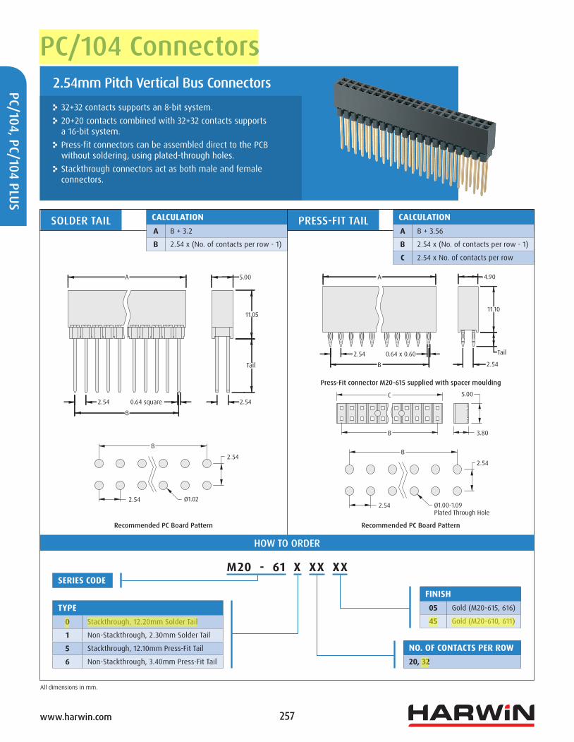
SOLDER TAIL PRESS-FIT TAILCALCULATIONA B + 3.2
B 2.54 x (No. of contacts per row - 1)
Recommended PC Board Pattern
CALCULATIONA B + 3.56
B 2.54 x (No. of contacts per row - 1)
C 2.54 x No. of contacts per row
M20 - 61 X XX XX
HOW TO ORDER
SERIES CODE
TYPE0 Stackthrough, 12.20mm Solder Tail
1 Non-Stackthrough, 2.30mm Solder Tail
5 Stackthrough, 12.10mm Press-Fit Tail
6 Non-Stackthrough, 3.40mm Press-Fit Tail
NO. OF CONTACTS PER ROW20, 32
FINISH05 Gold (M20-615, 616)
45 Gold (M20-610, 611)
Press-Fit connector M20-615 supplied with spacer moulding
32+32 contacts supports an 8-bit system. 20+20 contacts combined with 32+32 contacts supports a 16-bit system.
Press-fit connectors can be assembled direct to the PCB without soldering, using plated-through holes.
Stackthrough connectors act as both male and female connectors.
2.54mm Pitch Vertical Bus Connectors
PC/104 Connectors
B
2.54
2.54
Ø1.00-1.09 Plated Through Hole
Ø1.02
B
2.54
2.54
B
2.54 2.54
A
0.64 square
Tail
5.00
11.05
A 4.90
11.10
Tail
2.54
5.00
3.80
B
C
B
0.64 x 0.602.54

258www.harwin.com
PC/1
04, P
C/10
4 PL
US
All dimensions in mm.
Recommended PC Board Pattern
NON-STACKTHROUGH
STACKTHROUGH
NO. OF CONTACTS PER ROW30
M22 - 60 X 30 05
HOW TO ORDER
SERIES CODE
TYPE0 Stackthrough
1 Non-Stackthrough
Supports PCI bus. Stackthrough connectors act as both male and female connectors.
Available in Solder tail configuration.
2mm Pitch Vertical Bus Connectors
PC/104 Plus Connectors
FINISH05 Gold
58.00
Ø.90
2.00
60.20
60.20
58.00
9.35
11.99
2.000.50 square
2.00
8.00
2.00
58.00 8.00
9.35
2.282.000.50 square
2.00
4.006.00

259www.harwin.com
PC/104, PC/104 PLUS
All dimensions in mm.
NO. OF CONTACTS PER ROW30
M22 - 60 X 30 42SERIES CODE
TYPE2 Post Header
3 Post Receptacle
PC/104 PLUS POST HEADER PC/104 PLUS POST HEADER RECEPTACLE
HOW TO ORDER
Recommended PC Board Pattern Recommended PC Board Pattern
Accessory connectors for use with the PC/104 Plus range.
2mm Pitch Accessory Connectors
PC/104 Plus Connectors
FINISH42 Gold + Tin
60.00 60.20
8.00
58.0058.00
1.52
2.00
3.68
3.052.00
58.00
2.00
3.05
6.35
58.00
2.00
6.004.00 2.00
Ø0.80 Ø0.802.00
2.004.006.00
2.000.50 square 0.50 square
8.00

260www.harwin.com
PC/1
04, P
C/10
4 PL
US
All dimensions in mm.
Recommended PC Board Pattern
Accessory components for use with the PC/104 Plus range. The shroud is used to protect the long tails of the Stackthrough connector from the previous page, and ensures alignment with a mating connector. It self retains on the underside of the PCB after the Stackthrough connector has been soldered to the PCB, by latching into the four mounting holes.
Accessories
PC/104 Plus Connectors
PC/104 PLUS SHROUD
PC/104 SPACER
ORDER CODEM22-6043098
ORDER CODER6104-02
63.85
58.00
3.70
11.18
5.4511.43
13.30
63.35
7.87
Ø1.90
15.24
6.35 min
1.25 max
4.75
M3
5.00
M3