Embed Size (px)
Citation preview

CAD-600
PC-Based Encoder & Decoder for Kenwood’s FleetSync
Manual Revision: 2010-05-25 Covers Firmware Revisions: CAD-600: 2.0 & Higher Covers Software Revisions: CAD: 3.21 & Higher Covers Hardware Revisions: CAD: 219F
1
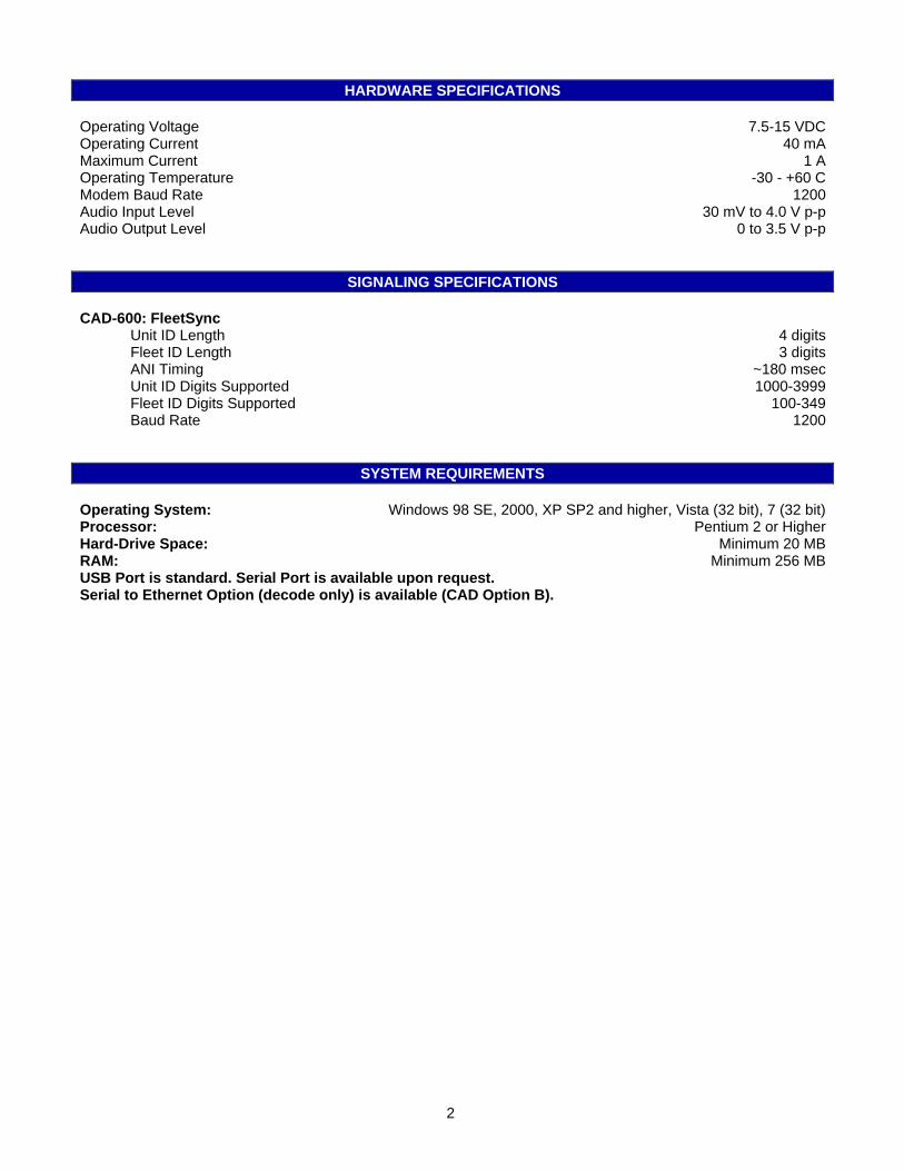
HARDWARE SPECIFICATIONS Operating Voltage 7.5-15 VDC Operating Current 40 mA Maximum Current 1 A Operating Temperature -30 - +60 C Modem Baud Rate 1200 Audio Input Level 30 mV to 4.0 V p-p Audio Output Level 0 to 3.5 V p-p
SIGNALING SPECIFICATIONS
CAD-600: FleetSync Unit ID Length 4 digits Fleet ID Length 3 digits ANI Timing ~180 msec Unit ID Digits Supported 1000-3999 Fleet ID Digits Supported 100-349 Baud Rate 1200
SYSTEM REQUIREMENTS
Operating System: Windows 98 SE, 2000, XP SP2 and higher, Vista (32 bit), 7 (32 bit) Processor: Pentium 2 or Higher Hard-Drive Space: Minimum 20 MB RAM: Minimum 256 MB USB Port is standard. Serial Port is available upon request. Serial to Ethernet Option (decode only) is available (CAD Option B).
2

INSTALLATION OVERVIEW 1. Test the radio for functionality. 2. Connect the CAD modem to the radio per the Hardware Installation Section of this manual. 3. Program the CAD software and modem per the Product Programming Section of this manual. * Midian is not responsible for any damage/loss resulting from the use of Midian’s products.
GENERAL INFORMATION
Midian’s CAD Series products work with Midian’s ANI-F or an ANI equipped radio to display ANI and Emergency ANI to identify which field unit is being keyed. The following is a list of benefits provided by ANI systems: • Allows dispatchers to know who he or she is talking to. • Identify system abusers. • Identify emergency conditions. • Assign calls fairly. In addition to decoding ANI and ENI, Midian’s CAD-600 offers selective calling for functions such as individual call, group call, disable/enable, etc. These functions can be used with a radio capable of these functions. Kenwood’s FleetSync: Kenwood’s FleetSync is a 1200 baud mobile data FFSK signaling format used by Kenwood for ANI, status, selective call, radio disable/enable, etc. Midian’s CAD-600 currently does not support 2400 baud Kenwood FleetSync or text messaging.
3
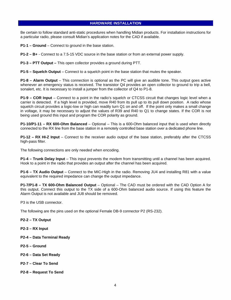
HARDWARE INSTALLATION Be certain to follow standard anti-static procedures when handling Midian products. For installation instructions for a particular radio, please consult Midian’s application notes for the CAD if available. P1-1 – Ground – Connect to ground in the base station. P1-2 – B+ - Connect to a 7.5-15 VDC source in the base station or from an external power supply. P1-3 – PTT Output – This open collector provides a ground during PTT. P1-5 – Squelch Output – Connect to a squelch point in the base station that mutes the speaker. P1-8 – Alarm Output – This connection is optional as the PC will give an audible tone. This output goes active whenever an emergency status is received. The transistor Q4 provides an open collector to ground to trip a bell, sonalert, etc. It is necessary to install a jumper from the collector of Q4 to P1-8. P1-9 – COR Input – Connect to a point in the radio’s squelch or CTCSS circuit that changes logic level when a carrier is detected. If a high level is provided, move R40 from its pull up to its pull down position. A radio whose squelch circuit provides a logic-low or high can readily turn Q1 on and off. If the point only makes a small change in voltage, it may be necessary to adjust the values of R39 and R40 to Q1 to change states. If the COR is not being used ground this input and program the COR polarity as ground. P1-10/P1-11 – RX 600-Ohm Balanced – Optional – This is a 600-Ohm balanced input that is used when directly connected to the RX line from the base station in a remotely controlled base station over a dedicated phone line. P1-12 – RX HI-Z Input – Connect to the receiver audio output of the base station, preferably after the CTCSS high-pass filter. The following connections are only needed when encoding. P1-4 – Trunk Delay Input – This input prevents the modem from transmitting until a channel has been acquired. Hook to a point in the radio that provides an output after the channel has been acquired. P1-6 – TX Audio Output – Connect to the MIC-High in the radio. Removing JU4 and installing R81 with a value equivalent to the required impedance can change the output impedance. P1-7/P1-8 – TX 600-Ohm Balanced Output – Optional – The CAD must be ordered with the CAD Option A for this output. Connect this output to the TX side of a 600-Ohm balanced audio source. If using this feature the Alarm Output is not available and JU8 should be removed. P3 is the USB connector. The following are the pins used on the optional Female DB-9 connector P2 (RS-232). P2-2 – TX Output P2-3 – RX Input P2-4 – Data Terminal Ready P2-5 – Ground P2-6 – Data Set Ready P2-7 – Clear To Send P2-8 – Request To Send
4
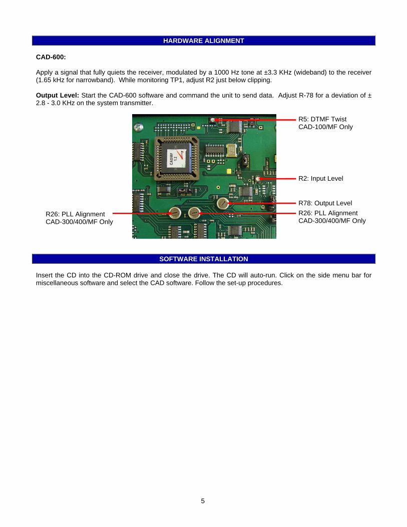
HARDWARE ALIGNMENT CAD-600: Apply a signal that fully quiets the receiver, modulated by a 1000 Hz tone at ±3.3 KHz (wideband) to the receiver (1.65 kHz for narrowband). While monitoring TP1, adjust R2 just below clipping. Output Level: Start the CAD-600 software and command the unit to send data. Adjust R-78 for a deviation of ± 2.8 - 3.0 KHz on the system transmitter.
R5: DTMF Twist CAD-100/MF Only
R2: Input Level
R78: Output Level R26: PLL Alignment CAD-300/400/MF Only
R26: PLL Alignment CAD-300/400/MF Only
SOFTWARE INSTALLATION Insert the CD into the CD-ROM drive and close the drive. The CD will auto-run. Click on the side menu bar for miscellaneous software and select the CAD software. Follow the set-up procedures.
5
PRODUCT PROGRAMMING General Tab:
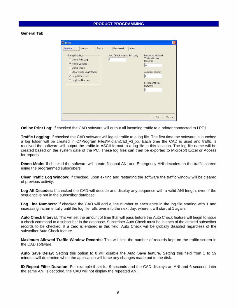
Online Print Log: If checked the CAD software will output all incoming traffic to a printer connected to LPT1. Traffic Logging: If checked the CAD software will log all traffic to a log file. The first time the software is launched a log folder will be created in C:\Program Files\Midian\Cad_v3_xx. Each time the CAD is used and traffic is received the software will output the traffic in ASCII format to a log file in this location. The log file name will be created based on the system date of the PC. These log files can then be exported to Microsoft Excel or Access for reports. Demo Mode: If checked the software will create fictional ANI and Emergency ANI decodes on the traffic screen using the programmed subscribers. Clear Traffic Log Window: If checked, upon exiting and restarting the software the traffic window will be cleared of previous activity. Log All Decodes: If checked the CAD will decode and display any sequence with a valid ANI length, even if the sequence is not in the subscriber database. Log Line Numbers: If checked the CAD will add a line number to each entry in the log file starting with 1 and increasing incrementally until the log file rolls over into the next day, where it will start at 1 again. Auto Check Interval: This will set the amount of time that will pass before the Auto Check feature will begin to issue a check command to a subscriber in the database. Subscriber Auto Check must be in each of the desired subscriber records to be checked. If a zero is entered in this field, Auto Check will be globally disabled regardless of the subscriber Auto Check feature. Maximum Allowed Traffic Window Records: This will limit the number of records kept on the traffic screen in the CAD software. Auto Save Delay: Setting this option to 0 will disable the Auto Save feature. Setting this field from 1 to 59 minutes will determine when the application will force any changes made out to the disk. ID Repeat Filter Duration: For example if set for 9 seconds and the CAD displays an ANI and 6 seconds later the same ANI is decoded, the CAD will not display the repeated ANI.
6
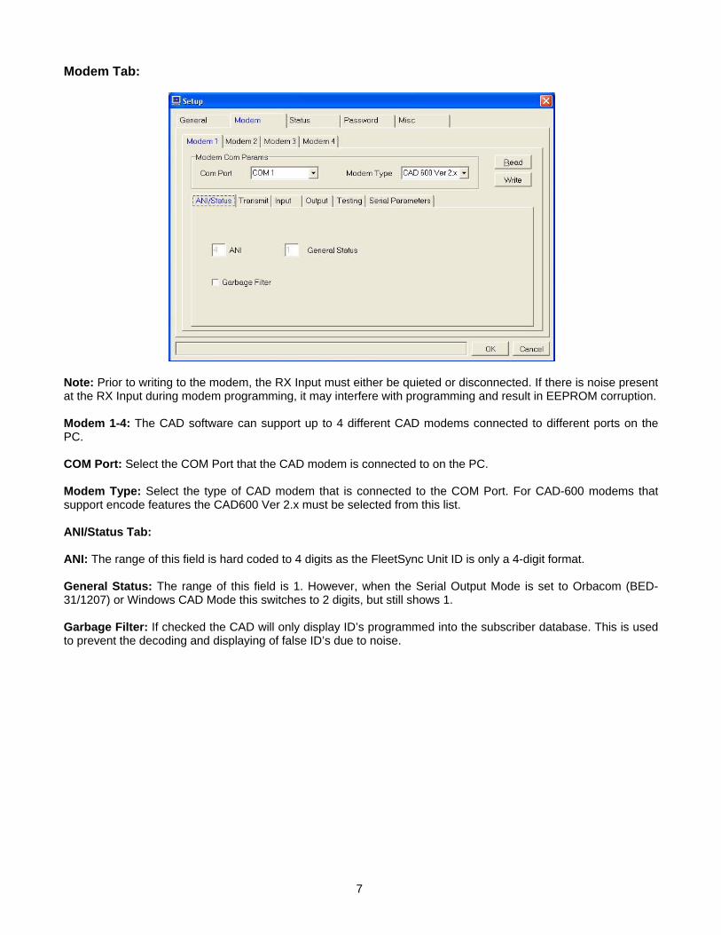
Modem Tab:
Note: Prior to writing to the modem, the RX Input must either be quieted or disconnected. If there is noise present at the RX Input during modem programming, it may interfere with programming and result in EEPROM corruption. Modem 1-4: The CAD software can support up to 4 different CAD modems connected to different ports on the PC. COM Port: Select the COM Port that the CAD modem is connected to on the PC. Modem Type: Select the type of CAD modem that is connected to the COM Port. For CAD-600 modems that support encode features the CAD600 Ver 2.x must be selected from this list. ANI/Status Tab: ANI: The range of this field is hard coded to 4 digits as the FleetSync Unit ID is only a 4-digit format. General Status: The range of this field is 1. However, when the Serial Output Mode is set to Orbacom (BED-31/1207) or Windows CAD Mode this switches to 2 digits, but still shows 1. Garbage Filter: If checked the CAD will only display ID’s programmed into the subscriber database. This is used to prevent the decoding and displaying of false ID’s due to noise.
7
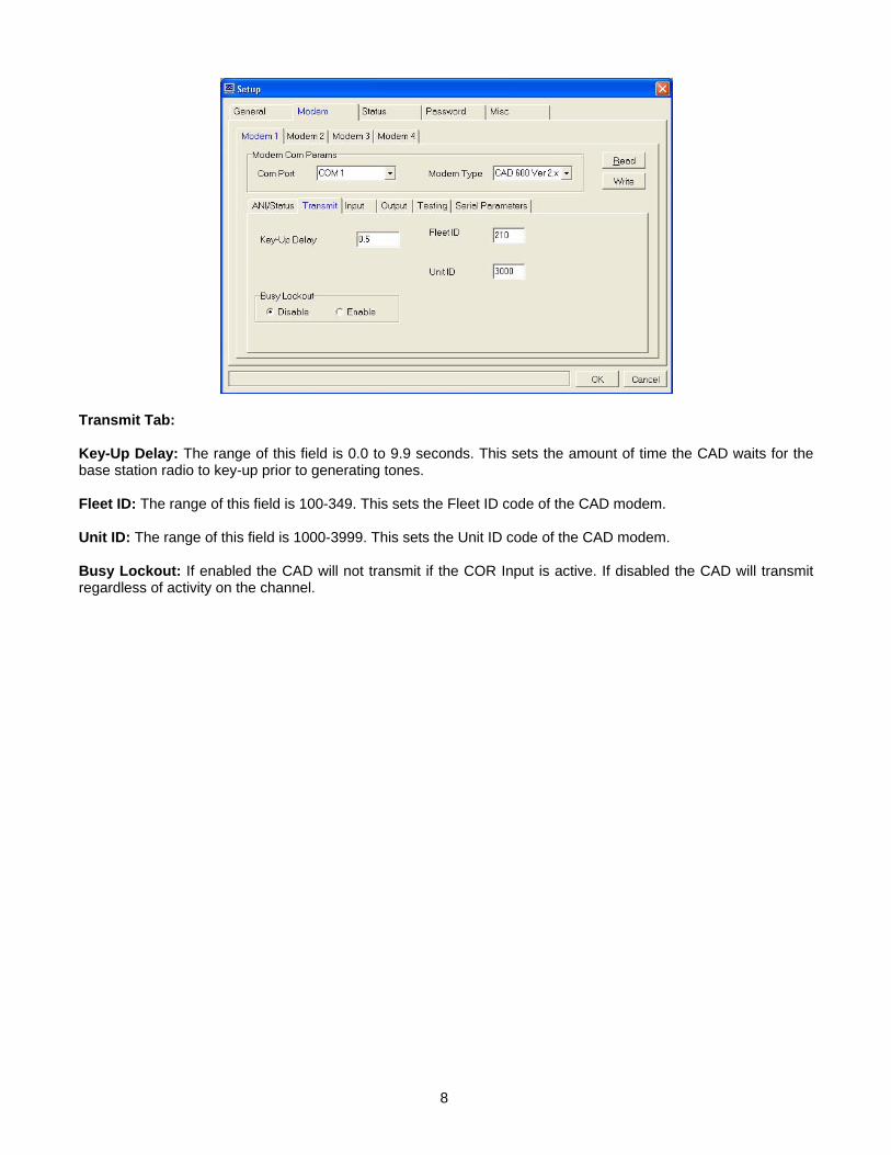
Transmit Tab: Key-Up Delay: The range of this field is 0.0 to 9.9 seconds. This sets the amount of time the CAD waits for the base station radio to key-up prior to generating tones. Fleet ID: The range of this field is 100-349. This sets the Fleet ID code of the CAD modem. Unit ID: The range of this field is 1000-3999. This sets the Unit ID code of the CAD modem. Busy Lockout: If enabled the CAD will not transmit if the COR Input is active. If disabled the CAD will transmit regardless of activity on the channel.
8
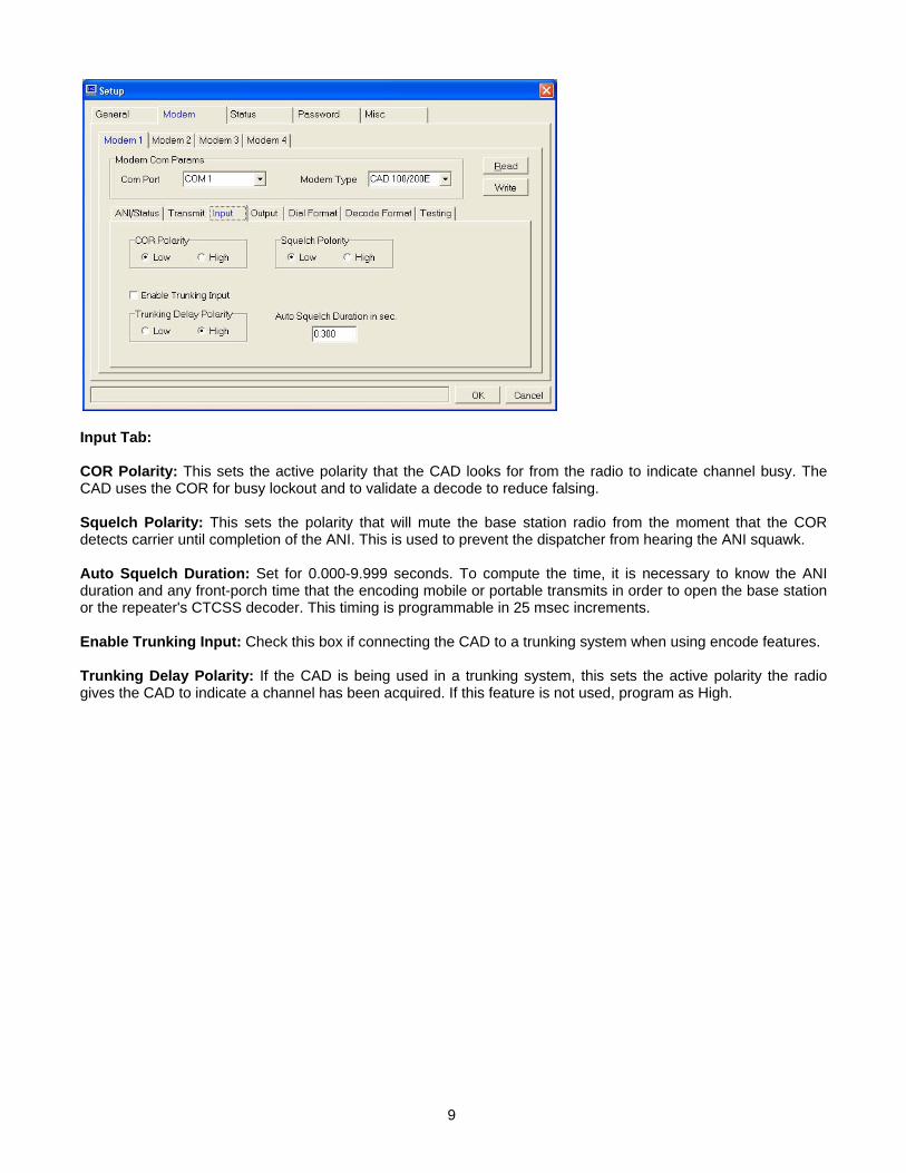
Input Tab: COR Polarity: This sets the active polarity that the CAD looks for from the radio to indicate channel busy. The CAD uses the COR for busy lockout and to validate a decode to reduce falsing. Squelch Polarity: This sets the polarity that will mute the base station radio from the moment that the COR detects carrier until completion of the ANI. This is used to prevent the dispatcher from hearing the ANI squawk. Auto Squelch Duration: Set for 0.000-9.999 seconds. To compute the time, it is necessary to know the ANI duration and any front-porch time that the encoding mobile or portable transmits in order to open the base station or the repeater's CTCSS decoder. This timing is programmable in 25 msec increments. Enable Trunking Input: Check this box if connecting the CAD to a trunking system when using encode features. Trunking Delay Polarity: If the CAD is being used in a trunking system, this sets the active polarity the radio gives the CAD to indicate a channel has been acquired. If this feature is not used, program as High.
9
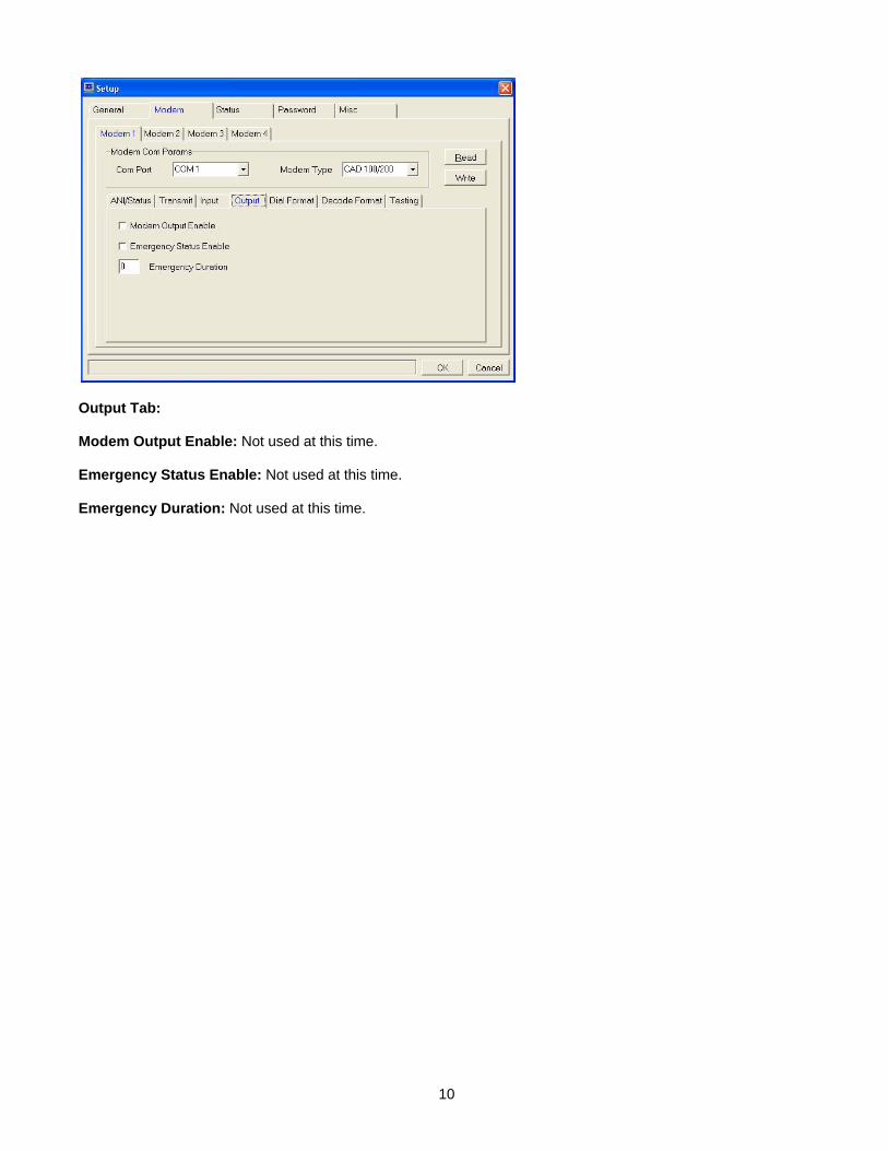
Output Tab: Modem Output Enable: Not used at this time. Emergency Status Enable: Not used at this time. Emergency Duration: Not used at this time.
10
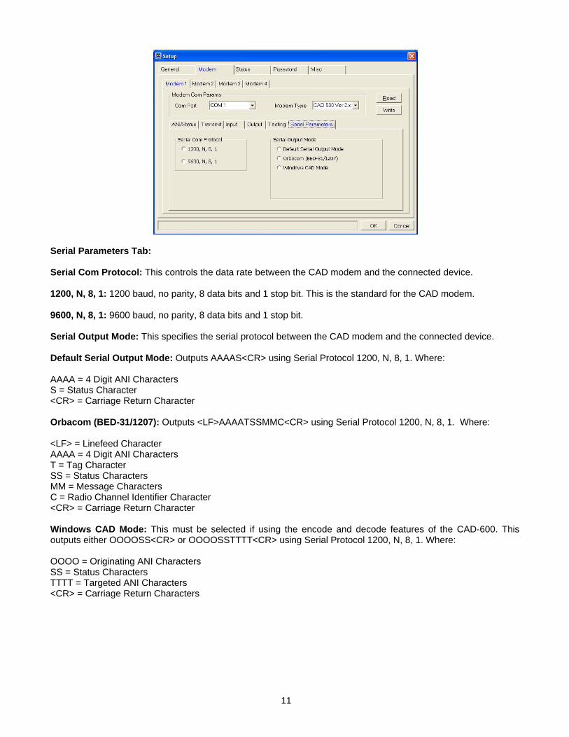
Serial Parameters Tab: Serial Com Protocol: This controls the data rate between the CAD modem and the connected device. 1200, N, 8, 1: 1200 baud, no parity, 8 data bits and 1 stop bit. This is the standard for the CAD modem. 9600, N, 8, 1: 9600 baud, no parity, 8 data bits and 1 stop bit. Serial Output Mode: This specifies the serial protocol between the CAD modem and the connected device. Default Serial Output Mode: Outputs AAAAS<CR> using Serial Protocol 1200, N, 8, 1. Where: AAAA = 4 Digit ANI Characters S = Status Character <CR> = Carriage Return Character Orbacom (BED-31/1207): Outputs <LF>AAAATSSMMC<CR> using Serial Protocol 1200, N, 8, 1. Where: <LF> = Linefeed Character AAAA = 4 Digit ANI Characters T = Tag Character SS = Status Characters MM = Message Characters C = Radio Channel Identifier Character <CR> = Carriage Return Character Windows CAD Mode: This must be selected if using the encode and decode features of the CAD-600. This outputs either OOOOSS<CR> or OOOOSSTTTT<CR> using Serial Protocol 1200, N, 8, 1. Where: OOOO = Originating ANI Characters SS = Status Characters TTTT = Targeted ANI Characters <CR> = Carriage Return Characters
11
Status Tab: System Status: This allows a System Status Message to be renamed or translated into a different language by entering the desired message in the Message column next to the original message. General Status: This allows a General Status Message to be renamed or translated into a different language by entering the desired message in the Message column next to the original message. Additionally, the desired digit for an Emergency status is checked in this table. If doing a 2-digit status, then 0-9 will need to be renumbered as 00-09. If doing a 2-digit status and more than 10 statuses are needed then from the last ID field press the down arrow and enter the new status number and create the desired message. Location X: This feature is not available in the CAD-600. Location Y: This feature is not available in the CAD-600. Password Tab: If the system administrator wishes to password protect certain functions, check the enable password box and then select which features to protect. When the protected features are accessed the user will be prompted to enter the password. Misc Tab: Color Tab: This tab enables the administrator to change the appearances of active text and the various backgrounds. Audio Tab: This tab enables the administrator to change the sounds of the Emergency and Error files, with other wav files. Images Tab: This tab enables the administrator to change the appearances of the icons on the subscriber screen.
12
OPERATION
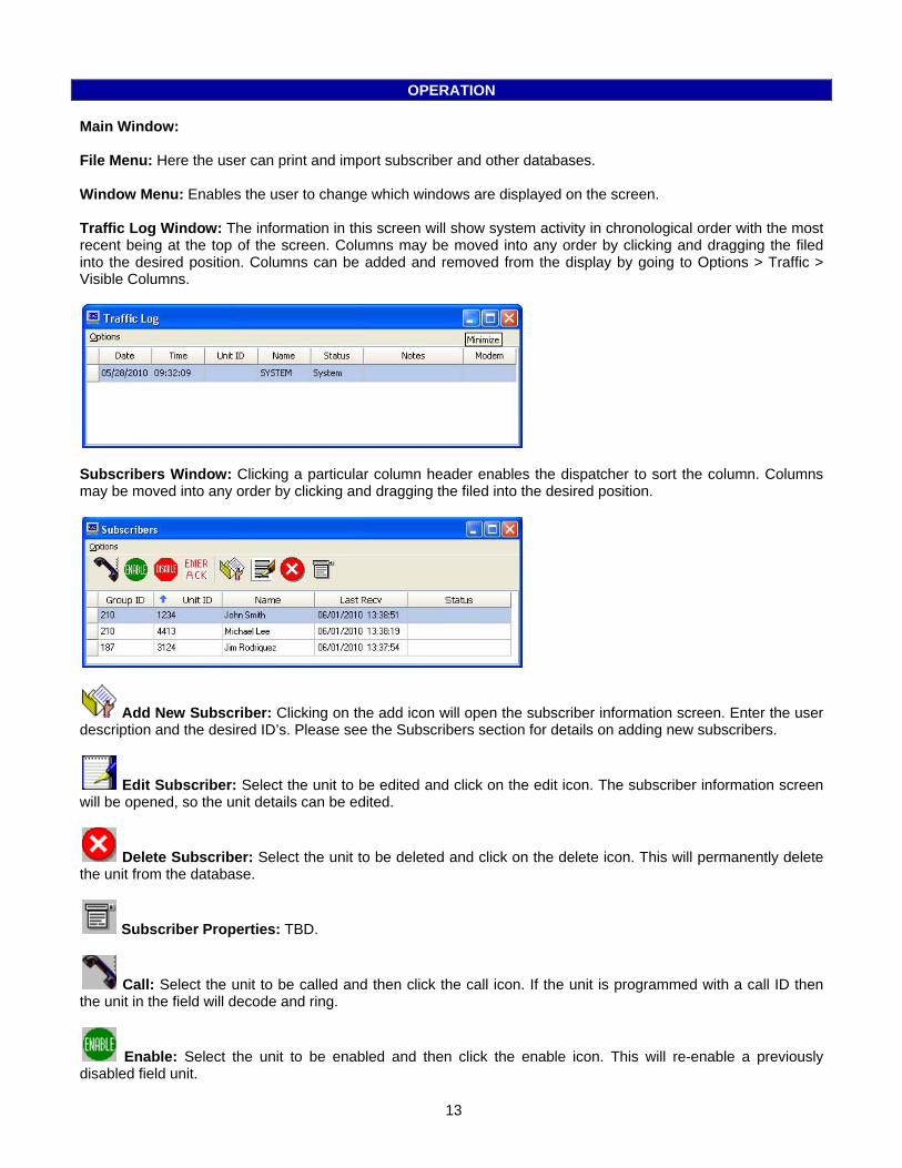
Main Window: File Menu: Here the user can print and import subscriber and other databases. Window Menu: Enables the user to change which windows are displayed on the screen. Traffic Log Window: The information in this screen will show system activity in chronological order with the most recent being at the top of the screen. Columns may be moved into any order by clicking and dragging the filed into the desired position. Columns can be added and removed from the display by going to Options > Traffic > Visible Columns.
Subscribers Window: Clicking a particular column header enables the dispatcher to sort the column. Columns may be moved into any order by clicking and dragging the filed into the desired position.
Add New Subscriber: Clicking on the add icon will open the subscriber information screen. Enter the user description and the desired ID’s. Please see the Subscribers section for details on adding new subscribers.
Edit Subscriber: Select the unit to be edited and click on the edit icon. The subscriber information screen will be opened, so the unit details can be edited.
Delete Subscriber: Select the unit to be deleted and click on the delete icon. This will permanently delete the unit from the database.
Subscriber Properties: TBD.
Call: Select the unit to be called and then click the call icon. If the unit is programmed with a call ID then the unit in the field will decode and ring.
Enable: Select the unit to be enabled and then click the enable icon. This will re-enable a previously disabled field unit.
13
Disable: Select the unit to be disabled and then click the disable icon. This will disable a field unit that is capable of the Deadbeat Disable or Radio Kill feature.
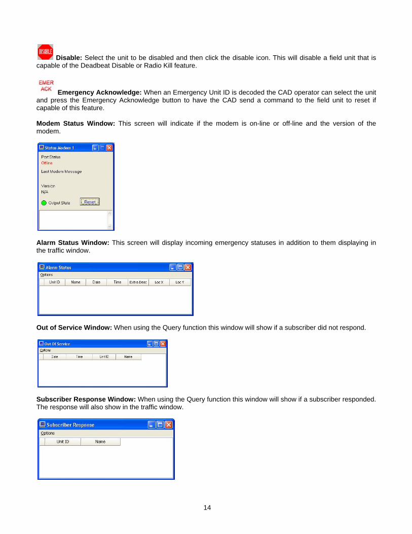
Emergency Acknowledge: When an Emergency Unit ID is decoded the CAD operator can select the unit and press the Emergency Acknowledge button to have the CAD send a command to the field unit to reset if capable of this feature. Modem Status Window: This screen will indicate if the modem is on-line or off-line and the version of the modem.
Alarm Status Window: This screen will display incoming emergency statuses in addition to them displaying in the traffic window.
Out of Service Window: When using the Query function this window will show if a subscriber did not respond.
Subscriber Response Window: When using the Query function this window will show if a subscriber responded. The response will also show in the traffic window.
14
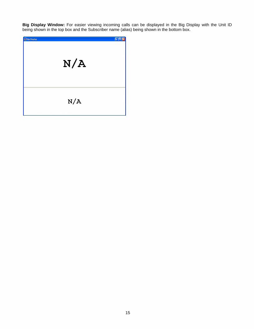
Big Display Window: For easier viewing incoming calls can be displayed in the Big Display with the Unit ID being shown in the top box and the Subscriber name (alias) being shown in the bottom box.
15
SUBSCRIBERS
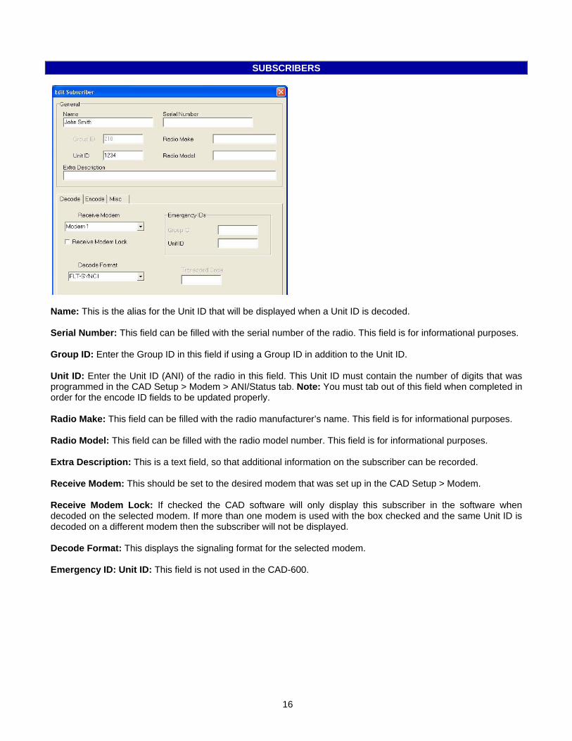
Name: This is the alias for the Unit ID that will be displayed when a Unit ID is decoded. Serial Number: This field can be filled with the serial number of the radio. This field is for informational purposes. Group ID: Enter the Group ID in this field if using a Group ID in addition to the Unit ID. Unit ID: Enter the Unit ID (ANI) of the radio in this field. This Unit ID must contain the number of digits that was programmed in the CAD Setup > Modem > ANI/Status tab. Note: You must tab out of this field when completed in order for the encode ID fields to be updated properly. Radio Make: This field can be filled with the radio manufacturer’s name. This field is for informational purposes. Radio Model: This field can be filled with the radio model number. This field is for informational purposes. Extra Description: This is a text field, so that additional information on the subscriber can be recorded. Receive Modem: This should be set to the desired modem that was set up in the CAD Setup > Modem. Receive Modem Lock: If checked the CAD software will only display this subscriber in the software when decoded on the selected modem. If more than one modem is used with the box checked and the same Unit ID is decoded on a different modem then the subscriber will not be displayed. Decode Format: This displays the signaling format for the selected modem. Emergency ID: Unit ID: This field is not used in the CAD-600.
16
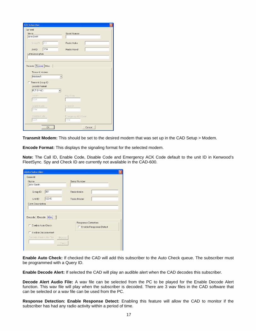
Transmit Modem: This should be set to the desired modem that was set up in the CAD Setup > Modem. Encode Format: This displays the signaling format for the selected modem. Note: The Call ID, Enable Code, Disable Code and Emergency ACK Code default to the unit ID in Kenwood’s FleetSync. Spy and Check ID are currently not available in the CAD-600.
Enable Auto Check: If checked the CAD will add this subscriber to the Auto Check queue. The subscriber must be programmed with a Query ID. Enable Decode Alert: If selected the CAD will play an audible alert when the CAD decodes this subscriber. Decode Alert Audio File: A wav file can be selected from the PC to be played for the Enable Decode Alert function. This wav file will play when the subscriber is decoded. There are 3 wav files in the CAD software that can be selected or a wav file can be used from the PC. Response Detection: Enable Response Detect: Enabling this feature will allow the CAD to monitor if the subscriber has had any radio activity within a period of time.
17

18
TECHNICAL NOTES
Radio Compatibility: Midian has taken the utmost care to ensure the CAD integrates with the radio with minimal impact to the features of the radio. However, some features may not be available in the radio when a CAD is used. If a feature is not available, please contact Midian to see if the feature can be added. International Windows Versions: Even though Midian has worked to make this product internationally compliant, Midian recognizes that there may be additional issues to be resolved.
MIDIAN CONTACT INFORMATION
Midian Electronics, Inc. 2302 East 22nd Street Tucson, Arizona 85713 USA Orders: 1-800-MIDIANS Phone: 520-884-7981 Fax: 520-884-0422 E-mail: [email protected] Web: www.midians.com