Embed Size (px)
Citation preview

PRODUCT DESCRIPTION
USISignal Interface
Ausgabe 1 - 8/2017


08/17 PRODUKTBESCHREIBUNG
Universal Signal Interface (USI)
Content USI Board ................................................... 1
Application notes ....................................... 1
View .......................................................... 2
Connectors ................................................ 3
Signals at the D-Sub 15 connector ........... 3
Application of the internal inputs at CN 300 ...................................................... 6
Signal description of the internal inputs at CN300 ....................................................... 7
Pin assignment jumper block .................... 8
Block diagram ........................................... 8
Circuit diagrams for signal inputs .............. 9
Circuit diagrams for signal outputs .......... 10
Replacing the controller .......................... 11

08/17 Rev. 01 PRODUCT DESCRIPTION
Universal Signal Interface (USI)
1
USI Board
Application notesNot for ALX 73x (PMA)
Utilization The USI (Universal Signal Interface) is an optional signal interface for the fol-lowing machines:
• 64-xx (24 V)• ALX 92x (5 V or 24 V)
The following machines come with an USI installed as standard:
• DPM (5 V or 24 V)• PEM (5 V or 24 V)
Article numbers:
• USI 5 V: A2062 (5 V signal voltage)• USI 24 V: A2345 (24 V signal voltage)
USI-equipped machines can for example control applicators or scanners. The input signals can be used to trigger the print-dispense-process. The out-put lines signal the operating status - e.g. material or ribbon end - so that the machine can be integrated completely into a system.
Compatibility DPM, ALX 92x: USI and AI (Applicator Interface) can not be installed both into the same device.
[1] Version designations on the USI board.
Requirements The functionality described in this section is only then fully available, if the following requirements are met:
• USI board: At least A2062-08 (5 V USI) or A2345-09 (24 V USI) or with a hig-her index number. Displaying the index number: Sticker on the board [1B, C].
A
BC

08/17 Rev. 01 PRODUCT DESCRIPTION
Universal Signal Interface (USI)
2
• USI controller: At least V6-T36 or a later version with a higher V-number. Dis-playing the version:– Sticker on the microcontroller [1A]– Parameter menu: SERVICE DATA > > MODULE FW VERS. > USI interface Controller version older than V6-T36: Update is only possible by
exchanging the controller (see chapter Replacing the controller on page 11).
Controller version V6-T36 or higher: Update can be done by loading new firmware (same procedure as for printer firmware update, see topic section Firmware ). Requirement: printer firmware of at least version 5.30 is installed.
• Printer firmware: 5.0 or higher. Displaying the firmware version:– Parameter menu: SERVICE DATA > > MODULE FW VERS. > System version– During powering up the printer
• Supply cable: The USI comes with the data cable connected firmly to the board; But the voltage cable has to be ordered separately (article no. A2059)
Accessories Product sensor: For connection to the 24 V USI, a completely assembled product sensor with 2 m cable and D-Sub15 connector is available (article no. A2682).
View
[2] USI-board (A2345).
JP8 Function5V internal voltage supply active on Pin2/DB-155V external voltage supply on Pin 2/DB-15
CPU board (CN101)
Connector for in-ternal USI inputs (CN 300)
SPS (optional)
Power supply (CN100)
USI signals (VB200)
Micro controller version number (here: V2)
USI board index number (here: 04)
08/17 Rev. 01 PRODUCT DESCRIPTION
Universal Signal Interface (USI)
3
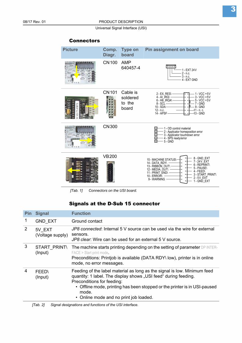
Connectors
Signals at the D-Sub 15 connector
Picture Comp. Diagr.
Type on board
Pin assignment on board
CN100 AMP 640457-4
CN101 Cable is soldered to the board
CN300
VB200
[Tab. 1] Connectors on the USI board.
1 - EXT 24V2 - n.c.3 - n.c.4 - EXT GND
2 - EX_RES\4 - AI_IRQ\6 - H8_IRQ4\8 - SCL
10 - SDA12 - n.c.14 - APSF
1 - VCC +5V3 - VCC +5V5 - VCC +5V7 - GND9 - GND
11 - n. c.13 - GND
1 - OD control material2 - Applicator homeposition error3 - Applicator touchdown error4 - SPS ready/error5 - GND
8 - GND_EXT7 - 24V_EXT6 - REPRINT\5 - PAUSE\4 - FEED\3 - START_PRINT\2 - 5V_EXT1 - GND_EXT
15 - MACHINE STATUS\14 - DATA_RDY\13 - RIBBON_OUT\12 - MEDIA_OUT\11 - PRINT_END\10 - ERROR\9 - WARNING
Pin Signal Function
1 GND_EXT Ground contact
2 5V_EXT(Voltage supply)
JP8 connected: Internal 5 V source can be used via the wire for external sensors.JP8 clear: Wire can be used for an external 5 V source.
3 START_PRINT\(Input)
The machine starts printing depending on the setting of parameter DP INTER-FACE > Start print mode.Preconditions: Printjob is available (DATA RDY\ low), printer is in online mode, no error messages.
4 FEED\(Input)
Feeding of the label material as long as the signal is low. Minimum feed quantity: 1 label. The display shows „USI feed“ during feeding.Preconditions for feeding:
• Offline mode, printing has been stopped or the printer is in USI-paused mode.
• Online mode and no print job loaded.
[Tab. 2] Signal designations and functions of the USI interface.

08/17 Rev. 01 PRODUCT DESCRIPTION
Universal Signal Interface (USI)
4
5 PAUSE\(Input)
A high-low-transition switches the printer into the USI-paused mode.A further high-low-transition switches the printer back into the online mode.
If parameter DP INTERFACE > Start print mode is set to Level high active or Level low active, any activating of the PAUSE\ signal stops the printing after the current label.
Features:• „USI Pause“ is displayed• ERROR\ is activ (low)• If a print job is available: DATA RDY\ is inactive (high)• Start print signals are suppressed• Reprint requests are proceeded after switching into online mode.• Precondition: START PRINT\ inactive (high).
6 REPRINT\(Input)
The last printed label is being reprinted as long as REPRINT\ is low.Minimum reprint quantity: 1 label.
Preconditions:• The label which is ought to be reprinted, must be ready printed and dis-
pensed.• Printer is in online mode.• If a REPRINT\ is triggered while the printer is in USI-pause mode, the
reprint will be proceeded as soon as the printer is switched back in on-line mode.
• Precondition: START PRINT\ inactive (high).
7 24V_EXT(Voltage supply)
Voltage supply for external sensors
8 GND_EXT(GND)
Ground contact
Pin Signal Function
[Tab. 2] (Forts.)Signal designations and functions of the USI interface.
08/17 Rev. 01 PRODUCT DESCRIPTION
Universal Signal Interface (USI)
5
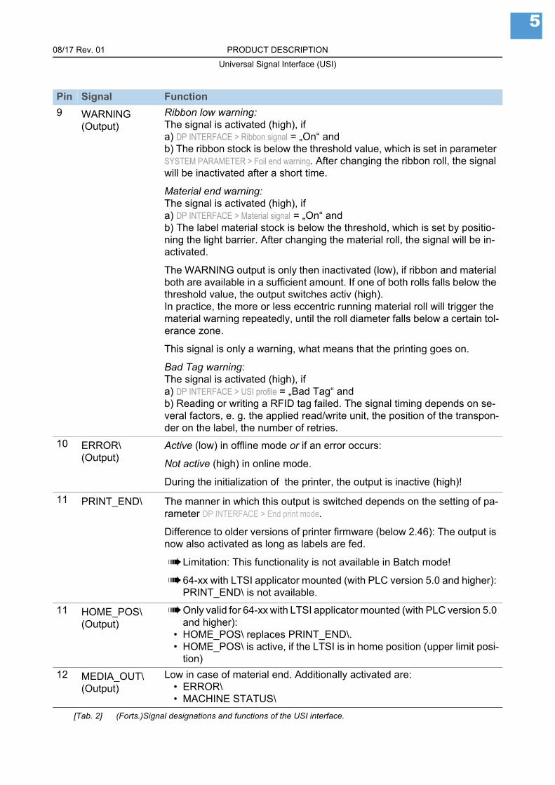
9 WARNING(Output)
Ribbon low warning:The signal is activated (high), ifa) DP INTERFACE > Ribbon signal = „On“ andb) The ribbon stock is below the threshold value, which is set in parameter SYSTEM PARAMETER > Foil end warning. After changing the ribbon roll, the signal will be inactivated after a short time.
Material end warning:The signal is activated (high), ifa) DP INTERFACE > Material signal = „On“ andb) The label material stock is below the threshold, which is set by positio-ning the light barrier. After changing the material roll, the signal will be in-activated.
The WARNING output is only then inactivated (low), if ribbon and material both are available in a sufficient amount. If one of both rolls falls below the threshold value, the output switches activ (high).In practice, the more or less eccentric running material roll will trigger the material warning repeatedly, until the roll diameter falls below a certain tol-erance zone.
This signal is only a warning, what means that the printing goes on.
Bad Tag warning:The signal is activated (high), ifa) DP INTERFACE > USI profile = „Bad Tag“ andb) Reading or writing a RFID tag failed. The signal timing depends on se-veral factors, e. g. the applied read/write unit, the position of the transpon-der on the label, the number of retries.
10 ERROR\(Output)
Active (low) in offline mode or if an error occurs:
Not active (high) in online mode.
During the initialization of the printer, the output is inactive (high)!
11 PRINT_END\ The manner in which this output is switched depends on the setting of pa-rameter DP INTERFACE > End print mode.
Difference to older versions of printer firmware (below 2.46): The output is now also activated as long as labels are fed.
Limitation: This functionality is not available in Batch mode!
64-xx with LTSI applicator mounted (with PLC version 5.0 and higher): PRINT_END\ is not available.
11 HOME_POS\(Output)
Only valid for 64-xx with LTSI applicator mounted (with PLC version 5.0 and higher):
• HOME_POS\ replaces PRINT_END\.• HOME_POS\ is active, if the LTSI is in home position (upper limit posi-
tion)
12 MEDIA_OUT\(Output)
Low in case of material end. Additionally activated are:• ERROR\• MACHINE STATUS\
Pin Signal Function
[Tab. 2] (Forts.)Signal designations and functions of the USI interface.

08/17 Rev. 01 PRODUCT DESCRIPTION
Universal Signal Interface (USI)
6
Application of the internal inputs at CN 300The following parameter settings are required to make the internal inputs useable:
PLC For usage with PLC:• DP INTERFACE > Interface type = USI Applicator• DP INTERFACE > Internal inputs = Enabled
OD sensor For useage with „OD sensor material“:• DP INTERFACE > Material signal = Enabled• DP INTERFACE > Internal inputs = Enabled
If PLC and „OD sensor material“ are ought to be used, all three parameter settings have to be done.
To all four inputs applies: The input is inactivated if it is connected to ground potential!
13 RIBBON_OUT\(Output)
Low in case of ribbon end. Additionally activated are:• ERROR\• MACHINE STATUS\
14 DATA_RDY\(Output)
Active (low) in online mode, if a printjob is loaded (--> detecting a loaded printjob). If the signal is active, the printer starts to print immediately after arrival of a start signal.
The signal toggles to deactivated, if• the print job is done, or• the printer is switched to stopped mode, offline mode or USI-pause mo-
de.
15 MACHINE STATUS\(Output)
This output is activated (low), if the printing has been interrupted by a dis-turbance or an error. Examples are: Pressure roll open, hood open, ribbon- or material end error, start print error or another fault that avoids printing.
The output is also activated during the initialization of the printer.
In comparison to ERROR\, MACHINE STATUS\ is not low if the printer has been switched to offline or pause mode.
64-xx with LTSI applicator mounted (with PLC version 5.0 and higher): MACHINE_STATUS\ is not available.
Pin Signal Function
[Tab. 2] (Forts.)Signal designations and functions of the USI interface.
08/17 Rev. 01 PRODUCT DESCRIPTION
Universal Signal Interface (USI)
7
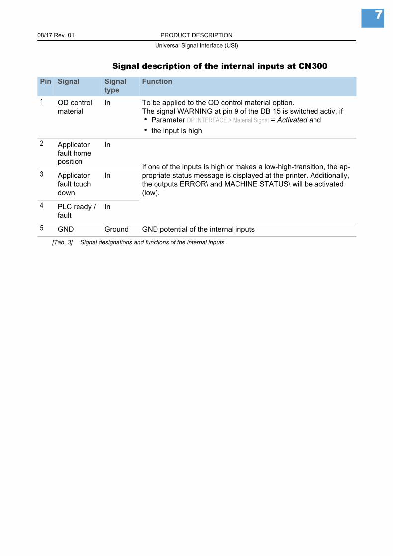
Signal description of the internal inputs at CN300
Pin Signal Signal type
Function
1 OD control material
In To be applied to the OD control material option.The signal WARNING at pin 9 of the DB 15 is switched activ, if• Parameter DP INTERFACE > Material Signal = Activated and
• the input is high
2 Applicator fault home position
In
If one of the inputs is high or makes a low-high-transition, the ap-propriate status message is displayed at the printer. Additionally, the outputs ERROR\ and MACHINE STATUS\ will be activated (low).
3 Applicator fault touch down
In
4 PLC ready / fault
In
5 GND Ground GND potential of the internal inputs
[Tab. 3] Signal designations and functions of the internal inputs

08/17 Rev. 01 PRODUCT DESCRIPTION
Universal Signal Interface (USI)
8
Pin assignment jumper blockEach signal of the D-Sub connector can be interrupted separately at the jumper block.
The voltage and ground wires are through-connected and cannot be interrup-ted [3]!
[3] Pin assignment jumper block
Block diagram
[4] Block diagram of the USI
GNDMACHINE STATUS\REPRINT\24 VDATA RDY\RIBBON OUT\PAUSE\
MEDIA OUT\
FEED\
PRINT END\
START PRINT\5 VGND
WARNINGERROR\APPLICATOR MODE
Ribbon Low
Machine Status\
Data Ready\
Ribbon Out\
Media Out\
Print End\
Error\
Reprint\
Pause\
Feed\
Start Print\
GND
GND
5V
24V
Applicator Mode
SPS Connectors
USI Connector
24V
5V
GND
GND
Ribbon Low
Reprint\
Pause\
Feed\
Start Print\
Machine Status\
Data Ready\
Error\
Print End\
Media Out\
Ribbon Out\
GND
Material Low
Home Pos. Error
Touch Down Error
SPS Ready\ /Error
CN300
Pin 1
Pin 2
Pin 3
Pin 4
Pin 5
Pin 6
Pin 7
Pin 8
Pin 9
Pin 10
Pin 11
Pin 12
Pin 13
Pin 14
Pin 15
Sub-D 15
Pin 1
Pin 2
Pin 3
Pin 4
Pin 5
JP202
JP201
JP200
JP203
JP204
JP205
JP206
CN200
CN201
CN202
CN203
CN204
JP300
JP301
JP302
JP303
US
IC
ontr
oller
US
Ilo
gic
En
gin
eC
on
tro
lle
r
USI Block Diagram
MUX
0
1
2
3
4
5
6
7internal Inputs
only
08/17 Rev. 01 PRODUCT DESCRIPTION
Universal Signal Interface (USI)
9
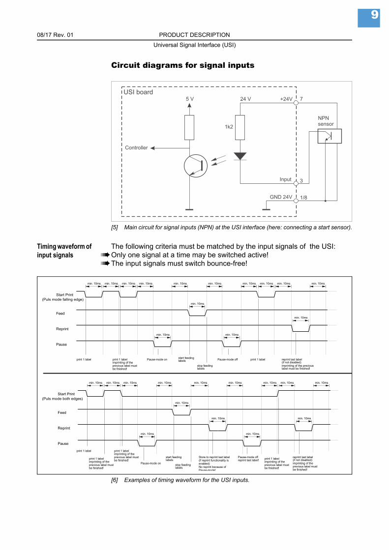
Circuit diagrams for signal inputs
[5] Main circuit for signal inputs (NPN) at the USI interface (here: connecting a start sensor).
Timing waveform of input signals
The following criteria must be matched by the input signals of the USI:Only one signal at a time may be switched active!The input signals must switch bounce-free!
[6] Examples of timing waveform for the USI inputs.
Store to reprint last label(if reprint functionality isenabled)No reprint because of Pause-mode!
min. 10ms
Pause-mode off
min. 10ms
Pause-mode on
min. 10ms
min. 10ms
min. 10ms
Pause
min. 10ms
print 1 label
Feed
print 1 label
min. 10ms min. 10ms
min. 10ms
min. 10ms
min. 10ms
print 1 label
min. 10ms
min. 10ms
min. 10msmin. 10ms
min. 10ms
min. 10ms
(Puls mode both edges)
reprint last label!
min. 10ms
min. 10ms
print 1 label
(Puls mode falling edge)
min. 10ms
min. 10msmin. 10ms
start feedinglabels
Reprint
Start Print
imprinting of theprevious label mustbe finished!
min. 10msmin. 10ms
Feed
stop feedinglabels
min. 10ms
min. 10ms
Reprint
print 1 label
min. 10ms
min. 10ms
Pause
reprint last label(if not disabled)imprinting of the previouslabel must be finished!
Start Print
imprinting of theprevious label mustbe finished!
imprinting of theprevious label mustbe finished! imprinting of the
previous label mustbe finished!
imprinting of theprevious label mustbe finished!
print 1 label
Pause-mode on
start feedinglabels
stop feedinglabels
Pause-mode off print 1 label reprint last label(if not disabled)

08/17 Rev. 01 PRODUCT DESCRIPTION
Universal Signal Interface (USI)
10
[7] Signal timing - to be met.
Circuit diagrams for signal outputs
[8] Main circuit (NPN) for signal outputs at the USI interface.
Max output current In the state of delivery (jumper 8 closed, cable A2059 connected), the supply voltages (5 V on pin 2 and 24 V on pin 8) are provided by the USI. The output current is limited:
Maximum current per output line: 50 mA; all output currents together may not exceed 700 mA.
[9] USI in the state of delivery: The voltage cable is connected, JP 8 is closed.
Reprint
Pause
Start Print
min. 10ms
Feed
min. 10ms
24 V
47k
Controller
5 VUSI board
Lo
ad
Output
Netzteil / Power Supply
USI board / USI-Platine
5 V
JP8
Kabel / CableA2059
24 V
0 V
24 V0 V
5 V0 V
Pin 2
Pin 7
Z01
19.c
dr
Pin 1 / 8Pin 2
Pin 1 / 8

08/17 Rev. 01 PRODUCT DESCRIPTION
Universal Signal Interface (USI)
11
External supply
Replacing the controllerA firmware update for controller versions older than V6-T36 can only be done by replacing the controller [10A].
Article number of the controller with the most recent firmware: A3379.
Version check Displaying the current controller version: SERVICE DATA > >MODULE FW VERS. > USI interface.
[10] The controller (A) contains the USI firmware.
Controller replacement
1. Switch the printer off, pull out the mains connector.
2. Open the rear hood.See topic section Service Mechanics , section „Housing“, chapter „Rear hood“.
3. Take the controller [10A] out of the socket.
4. Insert the new controller into the socket.The dent in the controller housing must show in the pictured direction!
CAUTION
In previous versions of this document, the external voltage supply of the USI was described.
External voltage supply without external current limiting elements is no longer permitted (risk of fire)a.
In case of applications that externally supply voltages, a current limiting element must be provided by the system integrator.
Examples of suitable current limiting elements in the supply circuit are:
• Poly fuse with UL 1434 approval24 VDC: Ihold = 650 mA; Umin = 30 V5 VDC: Ihold = 650 mA; Umin = 6 V
• Micro fuse according to IEC EN 6012724 VDC: T 630 mA L 250 V5 VDC: T 630 mA L 250 V
a. Due to an update of EN 60950-1.
Z0151.cdr
A


Novexx Solutions GmbHOhmstraße 385386 EchingGermany +49-8165-925-0www.novexx.com