Embed Size (px)
Citation preview

Passive Torque Regulation in an UnderactuatedFlapping Wing Robotic Insect
P. S. Sreetharan and R. J. WoodSchool of Engineering and Applied Science
Harvard UniversityCambridge, Massachusetts 02138
Abstract—Recent developments in millimeter-scale fabricationprocesses have led to rapid progress towards creating airborneflapping wing robots based on Dipteran (two-winged) insects.Previous work to regulate reaction forces and torques generatedby two flapping wings has largely focused on wing trajectorycontrol. An alternative approach introduces additional degreesof freedom to the wing flapping mechanism to passively regulatethese forces and torques. The resulting ‘mechanically intelligent’devices can execute wing trajectory corrections to realize desiredbody forces and torques without the intervention of an activecontroller.
This paper describes an insect-scale flapping wing aerome-chanical structure consisting of a piezoelectric bimorph poweractuator, an underactuated transmission mechanism, and pas-sively rotating wings. The transmission is designed to passivelymodulate wing stroke velocity to eliminate the net roll torqueimparted to the airframe.
The system is modeled as having four degrees of freedomdriven open-loop by a single power actuator. The theoreticalmodel predicts lift-generating wing trajectories as well as apassive reduction in roll torque experienced by the airframe.An at-scale structure constructed using Smart Composite Mi-crostructure (SCM) fabrication techniques provides experimentalsupport for the theoretical model.
I. I NTRODUCTION
Advances in millimeter scale fabrication processes haveenabled rapid progress towards the development of flappingwing micro air vehicles (FWMAVs) with system mass onthe order of 100mg [1]. However, flight stability and controlmechanisms for these mass and power limited systems remainactive areas of research.
Investigation into the aerodynamics of biological insectflight has produced approximate aerodynamic models allowingcomputationally inexpensive prediction of aerodynamic forcesand torques from wing trajectories [2], [3]. Accordingly,research into transmission and control mechanisms of flappingwing robotic insects has focused on control of wing trajectory.For example, the Berkeley Micromechanical Flying Insect(MFI) is a FWMAV platform with the ability to executea range of predetermined wing trajectories using a fullyactuated wing drive mechanism, neglecting elastic deformationof the transmission and wings [4]. In one notable exception,the Harvard Microrobotic Fly (HMF) has proven capableof realizing qualitatively biomimetic wing trajectories usingpassive compliance to allow variation of wing angles of attack[1]. The associated reduction in complexity has allowed this
aeromechanical platform to achieve a lift to weight ratiogreater than unity.
However, the benefits of underactuation and passive com-pliance can extend beyond simple reduction of mechanicalcomplexity, in particular for devices in which the distributionof forces and torques is of fundamental importance. A ubiqui-tous example is the automobile differential, an underactuatedmechanism commonly used to distribute engine power to twowheels. The differential incorporates an additional degree offreedom q2 to balance the torque delivered to each wheel(see Fig. 1). The differential fundamentally operates on wheeltorques instead of rotations; aided by passive mechanisms,the wheels can rotate along complex relative trajectories,maintaining traction on the ground without closed loop activecontrol.
to right wheel
to left wheel
A B
q1
q2
q1
q2
A – Bq1
q2
+
Fig. 1: A car differential balances output torques using anunderactuated mechanism. Degree of freedomq1 receivesengine torque whileq2 is unactuated.
Previous work has introduced the concept of PassiveAeromechanical Regulation of Imbalanced Torques (PARITy)in the context of insect-scale FWMAV design [5]. Embodyingthe PARITy concept, the ‘Drag PARITy’ is an underactuatedtwo degree of freedom FWMAV transmission that, analogousto an automobile differential, passively distributes power froma single actuator to balance torques delivered to two wings.Previous work has demonstrated its effectiveness within aplanar two degree of freedom system with fixed90 wingangles of attacks. Though the transmission was shown to

passively balance drag induced roll torques, a fixed90 angleof attack prevents the wings from generating lift.
This paper describes a lift-generating FWMAV design in-tegrating passively rotating wings with the Drag PARITytransmission. Variation of wing angle of attack is achievedby incorporating a compliant ‘wing hinge’ (Fig. 3c) into thewing, similar to the approach taken by [1]. The completedesign described in this paper has four degrees of freedom, asignificant increase in dynamic complexity over the two degreeof freedom system previously demonstrated in [5]. A singlepower actuator applies an oscillatory force, exciting motion inall four degrees of freedom through a variety of aerodynamicand inertial effects.
The underactuated flapping wing system is shown to executestable, qualitatively biomimetic, lift-generating wing trajecto-ries, indicating that the Drag PARITy is a viable transmis-sion design for insect-scale FWMAVs. A theoretical modelof the system is developed to investigate torque balancingcharacteristics in simulation. A control (‘Uncut’) trial with anominally symmetric system demonstrates passive balancingof roll torques imparted from each wing, compensating for fab-rication variation. In ‘1-Cut’ and ‘2-Cut’ trials, the system issimulated with successive removal of planform area from onewing (to provide an asymmetric disturbance) and is shown tocontinue successfully balancing roll torques, compensating forlarge inertial and aerodynamic wing asymmetries. By passivelydiverting more power to an underperforming wing, the designis also shown to indirectly compensate for imbalanced liftgeneration. Finally, an at-scale test device is constructed andobserved to execute wing trajectories supporting theoreticalpredictions. Prior to describing the experiment, however,thePARITy methodology for FWMAV control which motivatesthis investigation will first be outlined.
II. T HE PARITY METHODOLOGY
Though it would allow for a highly capable FWMAV,fully-actuated high-bandwidth control of wing trajectories hasnot been achieved on a 100mg platform. Millimeter-scalefabrication techniques have not yet demonstrated the requisitecomplexity within mass constraints. Furthermore, power andmass constraints are likely to limit the bandwidth of electronicsensing and control systems on these lightweight platforms.
Acknowledging these limitations, research has been con-ducted into ‘time-averaged’ wing control, seeking to controlaverage forces and torques by applying kinematic wing tra-jectory corrections on a long timescale (longer than a wingflapping period) [6]. Assuming that active control will notbe attempted at short (sub-wingbeat) timescales, the questionof the ideal short timescale behavior of a wing flappingmechanism is raised. Traditional kinematic control approachestacitly assume that rigid specification of wing trajectory is apreferred short timescale behavior.
However, the specific wing trajectory executed is not fun-damentally important to an FWMAV. Rather, an active flightcontrol system for a robotic flier uses the wings as a tool togenerate desired reaction forces and torques on its airframe.
“roll”
“pitch”
“yaw”
Fig. 2: Definition of roll, pitch, and yaw in the body frame.
Ideally, the wings should execute whatever trajectories arenecessary to realize these desired forces and torques.1 Adrivetrain that passively regulates these forces and torquesat a short timescale may simplify a longer timescale flightcontroller.
This alternative short term behaviour is conjectured to pro-duce systems that reject short timescale disturbances passively,alleviating requirements on active control systems. It is alsoexpected to compensate for some fabrication asymmetries,passively realizing the necessary adjustments to wing trajec-tory. This feature is extremely attractive, since fabricationvariation is a major concern for devices manufactured at themillimeter scale.
Under the PARITy methodology, long timescale control isachieved not by altering the wing trajectories directly, butby modulating the dynamics of the short timescale passivesystem. In the context of PARITy based FWMAV designs,control inputs would perturb the setpoint of short timescalesystem dynamics. For example, the ‘Drag PARITy’ drivetrainanalyzed in this paper passively balances body roll torquesimparted by each wing. However, actuation of an active controlinput could bias system dynamics such that the roll torqueimparted by one wing is passively regulated to be 10% higherthan that from the other wing. This local passive regulationmay enable direct active force and torque control at longtimescales, simplifying the control problem for mass-limitedflapping wing aeromechanical platforms.
Such active control mechanisms are the subject of futurework and will not be discussed in depth in this paper, buttheir brief mention serves to motivate the detailed analysisof simpler PARITy drivetrains without control capability.Thefollowing sections analyze a specific FWMAV system intro-ducing passively rotating wings to an actuated Drag PARITytransmission.
1The specific trajectory may be important for efficiency concerns, but isirrelevant for the purposes of stabilizing and controllingthe airframe.

III. T HE MECHANISM
A. Actuation
Piezoelectric actuation has been chosen due to its highbandwidth and high power density [7]. The actuator is a bi-morph PZT cantilever, with a peak-to-peak actuation strokeofapproximately 500µm. The base of the cantilever is groundedto the FWMAV airframe, while the output is affixed to thetransmission input (Fig. 3).
B. The Drag PARITy transmission
The Drag PARITy transmission is a millimeter scale planarlinkage constructed using Smart Composite Microstructure(SCM) fabrication techniques [8]. Unidirectional carbon fiberbeams form rigid links, while revolute joints are realized bypolymer flexure interconnects. The transmission has a singleactuated inputq1 and dual outputs driving the stroke anglesof each wing. The right wing stroke angleφR is illustrated inFig. 3c, while the left wing stroke angleφL (not shown) isthe analogous angle on the opposing wing.
q1
ActuatorAirframe
TransmissionWing
ψL
ψR
ψR
φR
(a)
(b)
(c)
q2
Wing Hinge
Fig. 3: (a) Diagram of the FWMAV design. (b) The fourdegrees of freedomq1, q2, ψL, andψR with respect to airframeground. (c) A view of the shoulder clarifying rotation angleψR. Right wing stroke angleφR can be determined fromq1andq2, as canφL of the left wing (not shown).
The transmission mechanism has two degrees of freedom;referring to Fig. 3b,q1 is actuated and allows power to beinjected into the system, whileq2 is passively determined.The degree of freedomq2 couples the upstroke of one wingto the downstroke of the other, allowing the mechanism topassively modulate wing stroke velocities to balance the rolltorques imparted by the wings on the airframe. An invertiblekinematic mapping relatesq1 andq2 to φR andφL; either pairof coordinates can be used to describe the configuration of thetransmission. A more detailed description of this mechanismis available in [5].
C. Wings
Wings consist of a 1.5µm polyester membrane supported bycarbon fiber venation, shown in Fig. 4. Fabricated wings havemasses under 1mg and are effectively rigid plates, exhibitinglimited deformation while flapping. In an approach pioneeredby [1], each wing is attached to a transmission output in serieswith a polymer flexure ‘wing hinge’ that allows the rigid wingto passively rotate around its longitudinal axis (see Fig. 3c).Compliance around the wing hinge axis allows the angle ofattack of each wing to vary passively while flapping.
IV. T HEORETICAL SIMULATION
A. Actuation
Actuator drive voltage is the single input to the simulationmodel. Using results from a laminate plate theory analysis,the first bending mode of the cantilever power actuator hasbeen modeled as a grounded spring in parallel with a voltage-proportional force [7]. The cantilever beam has a linearspring constant of 467mN/mm, and under a 100V amplitudesinusoidal drive signal, the actuator exerts a 120mN amplitudesinusoidal force. The drive signal is applied at 110Hz, nearmechanical resonance to increase stroke amplitude and limitreactive power.
B. Mechanical model
The transmission mechanism along with the wing hingehas been treated using a pseudo rigid body model [9]. Allcarbon fiber links are assumed to be infinitely stiff, whilepolymer flexure interconnects have been modeled as perfectrevolute joints in parallel with linear torsion springs. Springconstants for the transmission joints and wing hinges havebeen calculated using classical beam theory, and no dampingor other internal loss mechanisms have been modeled.
The wings themselves are the only significant inertias withinthe system and are the only inertias considered in the model.The mass of the SCM linkage mechanism is neglected. Thoughthe piezoelectric actuator mass is significant, due to thelarge transmission ratio the effective inertia of the actuatoris negligible and has been omitted from the model.
The final theoretical system has four degrees of freedom:two are contained within the Drag PARITy transmission, whilethe two wings each add a degree of freedom from theirrespective wing hinges. The orientation of each wing can befully described by the angle of the corresponding transmission

Fig. 4: The wing with membrane outline indicated for theUncut, 1-Cut, and 2-Cut trials, from top to bottom. Axis unitsare in mm. For inertial components in Table I, Thez andxcoordinate axes correspond to horizontal and vertical imageaxes, respectively.
Wing Left Right Right RightTrial All Uncut 1-Cut 2-CutIxx 49.0 47.1 40.6 32.8Iyy 50.5 48.6 42.0 34.1Izz 1.56 1.49 1.43 1.29Ixz 4.20 3.87 3.38 2.97Ω1 46.8 38.2 28.7 21.2Ω2 0.587 0.438 0.419 0.387Ω3 17.5 13.5 10.6 9.10Ω4 0.712 0.952 0.787 0.691
TABLE I: Inertial and aerodynamic parameters used for theleft and right wings for the Uncut, 1-Cut, and 2-Cut trials.All values have units of mg·mm2. The coordinate frame forinertial components is described in Figure 4.
output (the ‘stroke angle’φ) and the deflection angle of thewing hinge (the ‘rotation angle’ψ), illustrated for the rightwing in Fig. 3c.
C. Aerodynamic model
Aerodynamic effects have been simulated using a modelderived from the blade element method, assuming a perfectlyrigid wing planform. As modeled, lift and drag torques areproportional toφ2, the square of stroke velocity. Averaged liftand drag coefficients, strong functions of the rotation angleψ,were taken from experimental data collected from dynamicallyscaled models of a fruit fly (Drosophila melanogaster) wing
flapping in mineral oil [2]. Calculation of wing rotational mo-ments, important for realizing passive wing rotation, relies onadditional experimental work quantifying a non-dimensionalcenter of pressure locationdcp of fruit fly wings [3], [10].Rotational damping, proportional toψ2, the square of wingrotational velocity, has been modeled in accordance withexperimental and theoretical work on tumbling plates [11].
The complete aerodynamic model can be distilled into thefollowing four aerodynamic moments applied to each wing:
MN = −Ω1sgn(φ)φ2CN (ψ) (1)
MT = −Ω1sgn(φ)φ2CT (ψ) (2)
Mrd = −Ω2sgn(ψ)ψ2Crd (3)
Mr = −(
Ω3dcp(ψ) − Ω4
)
sgn(φ)φ2CN (ψ) (4)
In the previous set of equations,MT acts about an axisperpendicular to the wing plane and is the result of aero-dynamic forces acting in the wing plane.Mr andMrd arethe rotational and rotational damping moments, respectively,both acting on the wing around the wing hinge axis.MN actsabout an axis perpendicular to both the wing plane normal andthe hinge axis, and results from aerodynamic forces normalto the wing. The three aerodynamic coefficients, related totangential (CT ), normal (CN ), and rotational damping (Crd)aerodynamic forces, are described in [10].
The parametersΩ1, Ω2, Ω3, andΩ4 have units of mg·mm2
and can be calculated from the air densityρ and the specificwing morphology (see Table I for calculated values). Relatedwork has produced extensive experimental data verifying thatthis aerodynamic model adequately describes passive rotationof a single wing executing a predetermined stroke angle tra-jectory, along with generated lift forces [10]. This referencedwork contains a detailed description of the aerodynamic modelbriefly summarized here.
D. Mathematical formulation
For the theoretical model, the four coordinates specifyingthe device configuration were taken to be the left and rightwing stroke angles (φL andφR, respectively) along with theleft and right wing rotation angles (ψL andψR, respectively).These four quantities and their time derivativesφL, φR, ψL,andψR form the full eight element state vector of the dynamicsystem.
The body inertia of a robotic 100mg FWMAV is assumedto be orders of magnitude larger than the wing inertias. Thisassumption is representative of many biological insects, thoughsome exceptions exist (e.g. butterflies). Accordingly, thebodyframe has been treated as an inertial reference frame forthe purpose of predicting wing dynamics. This assumptionaccurately represents the grounded-airframe experiment un-dertaken in Section VI. Furthermore, theoretical wing dynamicpredictions are not expected to be impacted significantly bythenon-inertial nature of the body frame of a free flying FWMAV.
The equations of motion for the wings were derived froman Euler-Lagrange formulation assuming a fixed body frame.

3 4 5 6 7 8 9 10 11−30
−20
−10
0
10
20
30
Time (ms)
Roll Torque (mN*mm)
Drag PARITy
Baseline
Right Wing
Left Wing
Right Wing
Left Wing
(a)
3 4 5 6 7 8 9 10 11−30
−20
−10
0
10
20
30
Time (ms)
Roll Torque (mN*mm)
Drag PARITy
Baseline
Right Wing
Left Wing
Right Wing
Left Wing
(b)
3 4 5 6 7 8 9 10 11−30
−20
−10
0
10
20
30
Time (ms)
Roll Torque (mN*mm)
Drag PARITy
Baseline
Right Wing
Left Wing
Right Wing
Left Wing
(c)
Fig. 5: Theoretical roll torque experienced by the airframein the (a) Uncut, (b) 1-Cut, and (c) 2-Cut trials.
Since the only modeled inertias in the system are those of thetwo wings, the form of kinetic energyT is straightforward:
T =1
2
(
~ωL)T
IL~ωL +
1
2
(
~ωR)T
IR~ωR (5)
In the preceding equation,IL andIR are the inertial tensors
of each wing, constant in the wing frame and calculated aboutan origin defined by the closest point on the wing hinge axisto the shoulder axis (see Table I for calculated values). Thesmall shoulder offset of the Drag PARITy transmission hasbeen neglected, thus no translational kinetic energy termsarepresent. The term~ωL is the angular velocity of the left wing,a function ofφL, ψL, φL, and ψL. An analogous statementapplies to the right wing angular velocity~ωR.
The potential energyV has the following form:
V =1
2
9∑
i=1
kiγ2
i +1
2kaq
2
1(6)
The full device contains nine polymer flexure joints: twowing hinges along with seven internal to the Drag PARITytransmission. The quantitiesγi represent the angular deflectionof each flexure joint, functions ofφL, ψL,φR, andψR. Theconstantski represent the linearized torsional spring constantsfor each polymer flexure joint. The constantka is a linearspring constant describing the restoring force of the actuatorin response to its linear deflectionq1, itself a function ofφL
andφR.The LagrangianL is defined asL = T − V , and the equa-
tions of motion are derived from the Euler-Lagrange equationsfor each of the four coordinatespi ∈ φL, ψL, φR, ψR:
d
dt
∂L
∂pi
−∂L
∂pi
= τi (7)
Actuation force as well as aerodynamic torques appear in themodel as generalized forcesτi. Actuation occurs alongq1 (seeFig. 3) and aerodynamic torques are more naturally calculatedin the wing frame, so the appropriate Jacobians have been usedto map these forces onto the configuration variables.
All necessary Jacobian matrices and partial derivatives havebeen derived in closed analytical form for use within the
model, but the details have been omitted for brevity. Thefour 2nd order differential equations produced from (7) wereexpressed as a first order system of eight coupled nonlineardifferential equations. All theoretical results for the DragPARITy design are the result of numerically integrating thesedifferential equations using a Runge-Kutta based method asimplemented by the MATLAB function ode45.
3 4 5 6 7 8 9 10 11−5
0
5
10
15
20
25
30
35
Time (ms)
Yaw
Torque (mN*mm)
Drag PARITy
Baseline
Right Wing
Left Wing
Right Wing
Left Wing
Fig. 6: Yaw torque in the 1-Cut Trial.
The theoretical dynamics model has been used to investigatethe reaction torque regulating properties of the system inresponse to wing asymmetry. The system was compared witha baseline design in which the Drag PARITy transmission hasbeen replaced with a conventional transmission characterizedby fully actuated wing stroke angles. This baseline design isrealized by freezing the degree of freedomq2 of the DragPARITy toq2 = 0 (equivalent to the constraintφL = φR). Thisconstraint is accommodated by introducing a time-dependentLagrange multiplier to the Lagrangian:
L = T − V + λ(φL − φR) (8)
In the modified equations of motion given by (7),λ(t) repre-sents an internal constraint force and is calculated algebraicallyat each timestep to satisfy the kinematic constraint. It is tobe noted that this baseline three degree of freedom design isidentical to that of the HMF [1].
A control trial, which will be called the ‘Uncut’ trial, wassimulated using a structure mechanically and aerodynami-cally symmetric to the tolerances achievable with the SCMmanufacturing process. Two additional trials were undertakenwith intentionally asymmetric wing parameters, realized byremoving successive amounts of planform area from the distalextent of the right wing. These trials will be called the 1-Cut and 2-Cut trials, respectively. Images of the right wingplanform for all three trials are shown in Fig. 4. The left wingis nominally identical to the Uncut right wing for all threetrials.
All wing parameters were measured directly from wingsfabricated for the experimental test structure. Inertia tensors forthe wing were constructed using a baseline mass measurementcoupled with a photogrammetric process to determine thespatial distribution of wing mass. Aerodynamic parametersfor the wings were calculated using the photogrammetricallydetermined wing planform areas shown in Fig. 4. Sinceboth inertial and aerodynamic properties are highly sensitiveto wing mounting accuracy, the photogrammetric techniqueswere conducted in situ to avoid disturbing the device. Fabri-cation variation has resulted in measurable asymmetry evenin the Uncut case, apparent in theoretical and experimentalresults. See Table I for all calculated inertial and aerodynamicparameters.
In all trials, the Drag PARITy design is observed to executestable wing trajectories qualitatively similar to those executedby biological insects. Wing stroke anglesφL andφR oscillateover approximately100 with a rotation anglesψL andψR
oscillating between±60, approximately90 out of phase.These rotation angles correspond to an angle of attackα = 90
at stroke extents andα = 30 midstroke. Theoretical wingtrajectories are plotted in Figs. 9a and 9c.
WingWing
Transmission
Actuator
Airframe
Fig. 7: Front view of the experimental device.
V. PASSIVE BODY TORQUE REGULATION
The Drag PARITy design distinguishes itself from thebaseline design in the theoretical reaction torques impartedby the flapping wings on the airframe. The Drag PARITyis designed to balance the roll reaction torques imparted bythe flapping wings. Fig. 5 plots the theoretical roll torquesexperienced by the body of a FWMAV using a Drag PARITytransmission compared to that experienced by a FWMAVusing a conventional transmission. In all three trials, it isapparent that the Drag PARITy transmission has succeededin balancing the roll torques experienced by the body due toeach wing. The results are especially striking in the Uncut trial
(Fig. 5a), where the transmission has passively compensatedfor fabrication and assembly error present in the nominallysymmetric structure.
5 mm
WingWing
Actuator
Wing Hinges
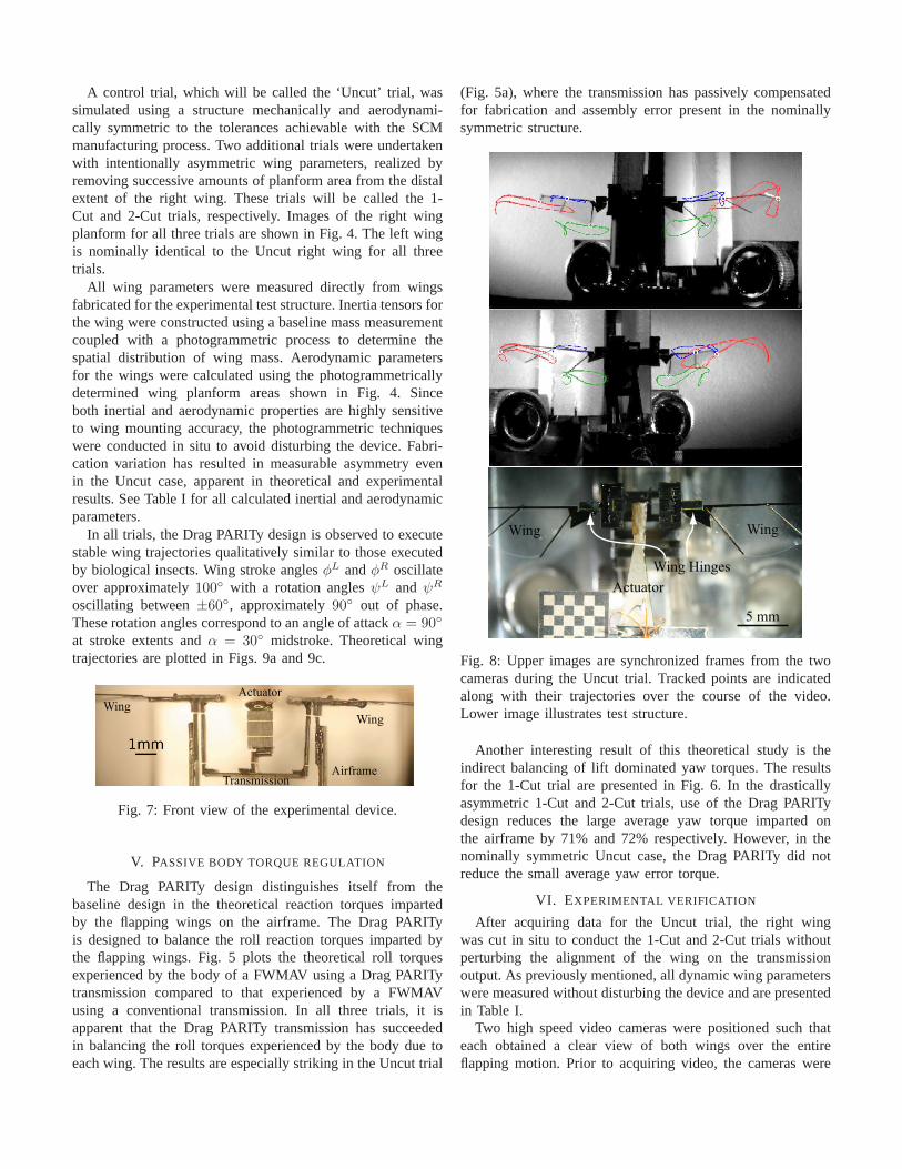
Fig. 8: Upper images are synchronized frames from the twocameras during the Uncut trial. Tracked points are indicatedalong with their trajectories over the course of the video.Lower image illustrates test structure.
Another interesting result of this theoretical study is theindirect balancing of lift dominated yaw torques. The resultsfor the 1-Cut trial are presented in Fig. 6. In the drasticallyasymmetric 1-Cut and 2-Cut trials, use of the Drag PARITydesign reduces the large average yaw torque imparted onthe airframe by 71% and 72% respectively. However, in thenominally symmetric Uncut case, the Drag PARITy did notreduce the small average yaw error torque.
VI. EXPERIMENTAL VERIFICATION
After acquiring data for the Uncut trial, the right wingwas cut in situ to conduct the 1-Cut and 2-Cut trials withoutperturbing the alignment of the wing on the transmissionoutput. As previously mentioned, all dynamic wing parameterswere measured without disturbing the device and are presentedin Table I.
Two high speed video cameras were positioned such thateach obtained a clear view of both wings over the entireflapping motion. Prior to acquiring video, the cameras were

0 1 2 3 4 5 6 7 8 9−80
−60
−40
−20
0
20
40
60
80
Time (ms)
Angle (deg)
Uncut
1−Cut
2−Cut
φL
ψL
(a)
0 1 2 3 4 5 6 7 8 9−80
−60
−40
−20
0
20
40
60
80
Time (ms)
Angle (deg)
Uncut
1−Cut
2−Cut
φL
ψL
(b)
0 1 2 3 4 5 6 7 8 9−80
−60
−40
−20
0
20
40
60
80
Time (ms)
Angle (deg)
Uncut
1−Cut
2−Cut
φR
ψR
(c)
0 1 2 3 4 5 6 7 8 9−80
−60
−40
−20
0
20
40
60
80
Time (ms)
Angle (deg)
φR
ψR
Uncut
1−Cut
2−Cut
(d)
Fig. 9: Left wing trajectories (a) predicted by theory and (b) observed experimentally, along with (c) theoretical and (d)experimental right wing trajectories. Each plot shows results from the Uncut, 1-Cut, and 2-Cut trials.
calibrated using routines from the CalTech Camera CalibrationToolbox for MATLAB [12]. Once calibrated, the toolboxallows reconstruction of three dimensional coordinates ofpoints identified in both camera views.
A 110Hz 200V (peak to peak) sinusoidal voltage wasapplied to the power actuator and synchronized high speedvideo was acquired from both video cameras at 10,000fps,or 91 frames per wingstroke period. Sample still frames areshown in Fig. 8.
Three easily distinguished features of the wing venationpattern were manually tracked across 300 frames for eachtrial. Identification of all three points in two camera viewsallows stereophotogrammetric reconstruction of the full wingorientation. The sinusoidal drive voltage applied to the actuatorhas been recorded and digitized at 5kHz, synchronized withthe high speed video stream.
The observed stroke and rotation angles are plotted as afunction of time in Fig. 9, along with predictions produced bythe theoretical model. Time synchronization has been achieved
by aligning the theoretical and experimental drive signals,omitted from the plots for clarity. The functional form of theapplied voltage signal as a function of time (in seconds) is:
V (t) = 100V + 100V · sin (110 · 2πt) (9)
From Fig. 9, it is immediately apparent that the theoreticalmodel accurately captures qualitative characteristics oftheexperimental model, with rotation angleψ exhibiting an ap-proximately90 phase lag behind the stroke angleφ. Further-more, the theory also accurately predicts oscillation amplitudesfrom applied drive voltage, an achievement considering thecomplexity of this nonlinear dynamic system.
Theoretically predicted trends in wing trajectories as theright wing planform is altered are apparent in experimentaldata. The model predicts a monotonic increase inφR(t) am-plitude as planform area is successively removed from the rightwing, coupled with an associated decrease in the amplitude ofφL(t). This trend is reflected in the experimental data as theDrag PARITy transmission passively diverts additional powerto the underperforming right wing. The model also predicts a

successive decrease in the amplitudes of both wing rotationsψL(t) andψR(t) as wing membrane is removed. This trend isapparent in the observed trajectory ofψL(t), though somewhatambiguous in the observed trajectory ofψR(t).
Among features not predicted by this simulation model arethe square-wave appearance of observed wing rotations andthe complex non-sinusoidal details of stroke angle trajectories.In future work, it is hoped that these discrepancies will bereduced by a more detailed theoretical model including, forex-ample, mechanical loss mechanisms and nonlinear descriptionsof polymer flexures to better predict dynamic characteristicsat large joint angles. The transmission design itself will berefined to limit unintended and difficult to model behavior.For example, one source of error in this experimental trialwas off-axis transmission compliance, resulting in measurabledeviation of the wings from their mean stroke planes.
VII. C ONCLUSION AND FUTURE WORK
This paper has presented further evidence supporting theutility of passive underactuated mechanisms in FWMAVs.Significantly extending previous work, the load balancingDrag PARITy transmission has been shown to be compatiblewith longitudinally compliant wing hinges allowing passivevariation of wing angle of attack. The resulting singly actuatedfour degree of freedom system has been shown to executestable qualitatively biomimetic flapping wing trajectories welldescribed by the associated theoretical model. Furthermore,the Drag PARITy transmission is shown to maintain its loadbalancing capabilities, passively altering wing trajectories soas to balance roll torques experienced by the FWMAV air-frame.
Future work exploring the PARITy methodology will pro-ceed along two parallel tracks:
1) Demonstrating long timescale control mechanisms2) Expanding passive regulation to larger subsets of body
forces and torquesAs previously mentioned, long timescale control in PARITyenabled FWMAVs will be achieved not by direct modulationof wing kinematic trajectories, but by active modification ofsystem dynamics. For example, the Drag PARITy transmissiondescribed in this paper exhibits short timescale dynamics thatbalance roll torques from each wing. An active control inputcould be introduced to bias these dynamics such that theypassively regulate the ratio of roll torquesτL
roll and τRroll from
the left and right wings, respectively, to a specified setpointq3:
τLroll/τ
Rroll = q3 (10)
Note thatq3 is fixed at unity for the simple Drag PARITytransmission. A variety of dynamic parameters within thetransmission, such as spring constants and link lengths, canbe actively modulated at long timescales to realize this biasedshort timescale behavior. The potential for simple controlrela-tionships such as (10), bypassing wing kinematics to directly
concern airframe forces and torques, is an exciting result of thePARITy methodology. Demonstration of such control featureswill motivate one track of future work.
A second research track involves introducing alternativeor additional passive degrees of freedom to an FWMAVdrivetrain to regulate different or expanded subsets of thebody forces and torques produced by the wings. The DragPARITy drivetrain is a mechanically intelligent device thathas demonstrated regulation of body roll torques, arising inpart from aerodynamic drag. In one nascent concept, carefulintroduction of passive features may enable an FWMAVdrivetrain that directly regulates yaw torques arising fromaerodynamic lift in addition to roll torques. The design spaceof such mechanically intelligent structures is vast, and futurework will attempt to produce a variety of force and torqueregulating FWMAV structures.
The PARITy methodology has the potential to simplify flightcontrol of insect-scale robotic FWMAVs. It is hoped thatfuture research into this novel methodology will provide toolsto increase aerodynamic performance and reduce requisitesystem complexity, hastening the arrival of an autonomous100mg-scale robotic FWMAV.
ACKNOWLEDGEMENT
The authors gratefully acknowledge support from the Na-tional Science Foundation (Award No. CMMI-07466 38).Any opinions, findings and conclusions or recommendationsexpressed in this material are those of the authors and do notnecessarily reflect those of the National Science Foundation.
REFERENCES
[1] R. J. Wood, “The first takeoff of a biologically inspired at-scale roboticinsect,” IEEE Trans. Rob., vol. 24, pp. 341–347, 2008.
[2] M. H. Dickinson, F. O. Lehmann, and S. P. Sane, “Wing rotation and theaerodynamic basis of insect flight,”Science, vol. 284, pp. 1954–1960,1999.
[3] W. B. Dickson, A. D. Straw, C. Poelma, and M. H. Dickinson, “Anintegrative model of insect flight control,” inProc. AIAA AerospaceSciences Meeting and Exhibit, Reno, NV, January 2006.
[4] R. S. Fearing, K. H. Chiang, M. H. Dickinson, D. L. Pick, M.Sitti,and J. Yan, “Wing transmission for a micromechanical flying insect,”J. Micromechatronics, vol. 1, no. 3, pp. 221–237, 2001.
[5] P. S. Sreetharan and R. J. Wood, “Passive aerodynamic dragbalancingin a flapping wing robotic insect,”J. Mech. Des., vol. 132, 2010.
[6] X. Deng, L. Schenato, and S. Sastry, “Flapping flight for biomimeticrobotic insects: Part ii-flight control design,”IEEE Trans. Rob., vol. 22,no. 4, pp. 789–803, 2006.
[7] R. J. Wood, E. Steltz, and R. S. Fearing, “Optimal energy densitypiezoelectric bending actuators,”Sensors & Actuators: A. Physical, vol.119, no. 2, pp. 476–488, 2005.
[8] R. J. Wood, S. Avadhanula, R. Sahai, E. Steltz, and R. S. Fearing,“Microrobot design using fiber reinforced composites,”J. Mech. Des.,vol. 130, 2008.
[9] L. L. Howell, Compliant Mechanisms. John Wiley and Sons, Inc.,2001.
[10] J. P. Whitney and R. J. Wood, “Aeromechanics of passive rotation inflapping flight,” J. Fluid Mech., vol. In Press, 2010.
[11] A. Andersen, U. Pesavento, and Z. Wang, “Unsteady aerodynamics offluttering and tumbling plates,”J. Fluid Mech., vol. 541, pp. 65–90,2005.
[12] J. Y. Bouguet, “Camera calibration toolbox for matlab,” 2008,http://www.vision.caltech.edu/bouguetj/calibdoc/index.html.