Embed Size (px)
Citation preview

Image Credit: Alex Bruce

G R E E N B U I L D I N G U N I T E D PA S S I V E R O W H O U S E M A N U A L 3
Table of Contents
Welcome
Introduction: Why Passive House?
Chapter 1: Opportunity Seeking
Chapter 2: Building Enclosures
Chapter 3: Connections
Chapter 4: Materials
Chapter 5: Windows + Doors
Chapter 6: Energy
Chapter 7: Heating + Cooling
Chapter 8: ERV + DHW Systems
Chapter 9: Testing, Balancing, + Verifying
Conclusion
Appendix
Glossary

G R E E N B U I L D I N G U N I T E D PA S S I V E R O W H O U S E M A N U A L 4
Welcome
If you are looking to renovate a rowhome as sustainably as possible, this Passive Rowhouse Manual (Manual) is for you. The Manual provides guidance for the construction or renovation of residential rowhomes (hereinafter, rowhouses) using sustainable and renewable energy technology, materials, practices, and procedures. There are many ways to define and quantify sustainability, and this Manual uses the Passive House standard - a holistic approach to designing high performance building - as the basis for sustainable and renewable practices and recommendations.
The Manual comes to you from us, the Green Building United Passive House Community, a group of volunteers dedicated to incorporating Passive House design and construction into mainstream practice. Our Community includes engineers, architects, designers, planners, consultants, students, and generally interested community members - from beginner to expert. We are excited to share our collective experience, wisdom, and knowledge with you!
We created this Manual for developers, contractors, and other professionals who have general familiarity or technical expertise in the Passive House standard. We encourage Manual users who are unfamiliar with Passive House building techniques to seek additional resources that are referenced within the Manual or readily available from other sources. This Manual is not intended to replace certified design professionals. If you are a builder, homeowner, and/or other professional and generally interested in the process of constructing or renovating residential rowhouses, this Manual is a useful guide, but not meant to be used as a stand alone document.
Each of the nine chapters is focused on a topic specific to Passive House design and construction, from determining whether Passive House is feasible for your project all the way through testing and verifying for Passive House certification. Construction and renovation guidance within this Manual has been informed and supported by data garnered from charrettes we conducted throughout 2018 and 2019, known as the Passive Rowhouse Demonstration Project. Recommendations are also backed by years of experience working on personal and professional Passive House projects, as well as general design and construction projects.

G R E E N B U I L D I N G U N I T E D PA S S I V E R O W H O U S E M A N U A L 5
The Passive Rowhouse Demonstration Project was an effort to explore the feasibility of renovating existing Philadelphia rowhouses to achieve the Passive House standard. We learned a lot during the span of those charrettes and now want to share lessons and best practices with you. Throughout the Manual we provide examples from real world, under construction projects - which informed our Demonstration Project charrettes - to illustrate concepts and strategies. We will be supplementing the Manual with case studies in the future to further support and guide your Passive Rowhouse endeavors.
This document could not have come to fruition without the extensive dedication of our Passive House Community. Thank you to the many volunteers for dedicating thousands of hours developing and implementing Demonstration Project charrettes, and for collaborating on authoring, editing, and illustrating the Passive Rowhouse Manual.
WELCOME
PASSIVE ROWHOUSE TEAM
Wolfram Arendt, LAYER Architecture
Jeremy Avellino, Bright Common
Leslie Billhymer, Corona Partners
Laura Blau*, BluPath Design, GreenSteps
Alex Bruce*, SITIO
Ilka Cassidy, Holzraum System
Amy Cornelius*, GreenBeams
Mike Cronomiz, Re:Vision Architecture
Shannon Crooker*, Sustainable Energy Fund
Kit Elsworth, KieranTimberlake
Stephen Finkelman*, Kitchen & Associates
Neil Goldman*, Hanson Fine Building
Steve Hessler, Holzraum System LLC
David Hincher, NELSON
Angela Iraldi*, Re:Vision Architecture
Jon Jensen*, MaGrann Associates
Scott Kelly, Re:Vision Architecture
Chris Lee, JacobsWyper Architects
Kent Lessly, Lessly Associates, LLC
Charles Loomis*, Loomis McAfee Architects
Darren Macri, Wythe Windows
Andrew McDowell
Jim Muhaw, Rothoblaas
Shannon Pendleton*, Sanderson Sustainable Design
Kevin Raab, Klearwall
Reid Rowlands*, World Class Supply
Matt Seip, Grain High Performance Homes
David Salamon, Re:Vision Architecture
Mark Stutman, New Ecology
Paul Thompson*, BluPath Design, GreenSteps
Craig Toohey, 475 High Performance Building Supply
Stephen Wayland*, Bruce E. Brooks & Associates
Justin Weisser*
Leah Wirgau*, Green Building United
Sebastian Zawierucha*, Solar Consultant
*Indicates Manual authors, editors, and graphic designers

G R E E N B U I L D I N G U N I T E D PA S S I V E R O W H O U S E M A N U A L 6
Grant Funder
Passive House Community Sponsors
Last but not least, thank you to our grant funder, Sustainable Energy Fund, and our many sponsors - 475 High Performance Building Supply, INTUS Windows, Kitchen & Associates, MaGrann Associates, McDonald Group, SIGA, and Stego Industries, LLC - for supporting ongoing Passive House Community activities, including the development of this Manual.
WELCOME

G R E E N B U I L D I N G U N I T E D PA S S I V E R O W H O U S E M A N U A L 7
One last note before you get started...This Manual is packed with a lot of useful information and there are key pieces we do not want you to miss! Keep an eye out for these icons as you move through the process.
Demonstration Project: Look for this icon to learn how Manual concepts played out in our team’s real world Passive Rowhouse retrofit charrettes.
Important: Take it from us and look for this icon to avoid pitfalls that can occur with Passive House retrofits.
Tool Kit: We want you to be prepared for success. Look for this icon to glean tips and tricks that you can add to your own Passive House “tool kit.”
WELCOME
Also make sure to check out the glossary for key words that may be unfamiliar, but are integral to Passive House retrofits.

G R E E N B U I L D I N G U N I T E D PA S S I V E R O W H O U S E M A N U A L 8
A NOTE ABOUT CERTIFICATION
Although not a requirement for certification, Passive House principles support two relevant topics for the built environment: electrification and decarbonization. This Manual emphasizes the importance of building decarbonization through electri-fication with no use of combustion fuels (natural gas or oil) - supporting net zero energy systems and ultimately creating a smaller carbon impact from both operational and embodied carbon emissions.
Introduction: Why Passive House?
The Passive House building standard serves as a basis for understanding energy efficiency and how to achieve it through a holistic, building science approach. Using traditional construction methods and materials to achieve the highest results, Passive House design principles can be applied to all building types (not just houses) to achieve high performance. As recognized by the U.S. Department of Energy in 2012, the standard offers proof of performance, giving credence to its application in your rowhouse project.
Passive House buildings also help curb climate change impacts. With over 70% of Philadelphia’s carbon emissions coming from the building sector, over 333,000 rowhouses in the city, and a significant percentage of rowhouses in need of repair, we - as the Green Building United Passive House Community - identified rowhouse renovation as a unique avenue to mitigate climate change while improving quality of life for Philadelphia residents.
By applying Passive House design and construction methodologies to rowhouses with the guidance of this Manual, a “Passive Rowhouse” may be realized. When compared to a typical rowhouse, a Passive Rowhouse will feature: higher energy efficiency, lower energy demand, lower utility costs, longer lasting materials, and better air quality and indoor comfort. In other words, occupants can feel good about living in a home that saves them money, is better for their health, and has a smaller environmental footprint.

G R E E N B U I L D I N G U N I T E D PA S S I V E R O W H O U S E M A N U A L 9
Insulation + Air Sealing Heating + CoolingVentilationWindows + DoorsDesign
There are five basic principles that outline the Passive House approach:
1. Continuous insulation with no thermal bridging2. Airtight, draft-free construction3. High performance windows and doors4. Balanced heat and moisture recovery ventilation5. Minimal space conditioning systems
These principles are illustrated in Figure 1. Construction quality, contractor education, and verification will drive the first principle; the intelligence of the design will drive the second. Properly specified and installed windows and doors will drive the third principle; engineering and commissioning the fourth. The fifth is the result of all four principles.
INTRODUCTION
To assess whether Passive House is right for your rowhouse project, you and your team will want to identify opportunities and possible constraints, which we will cover in the first chapter: Opportunity Seeking.
Figure 1: Five Passive House Principles

G R E E N B U I L D I N G U N I T E D PA S S I V E R O W H O U S E M A N U A L 10
Opportunity Seeking
C H A P T E R 1
Section 1: Overview
The rowhouse building typology presents unique opportunities, challenges, and risks that should be evaluated fully before construction or renovation begins, especially when seeking to achieve Passive House certification. To help guarantee success, this chapter introduces key strategies to implement when planning a Passive Rowhouse retrofit project.
Basic rowhouse livability means the building is structurally sound, sheds water, and has no hazardous materials or dangerous conditions. The Philadelphia Rowhouse Manual (Figure 2) is an excellent source of information for maintaining and renovating Philadelphia rowhouses, and when supplemented with information from this Manual, can guide you toward a Passive House certified rowhouse.
Renovating any building involves a complex decision-making process: What is the budget and schedule? What does the municipality allow? Who is going to design and build it? What about use and aesthetics? Are there existing building conditions of which you want to be aware - such as inefficient mechanical systems, water in the basement, or drafty windows?
Adding Passive House elements to the traditional construction process can be readily achieved by following your preferred certification program requirements (PHIUS or PHI; see call outs on page 11). Due to the technical nature of these elements, a credentialed Passive House Consultant (CPHC, CPHD) is a necessary part of your construction team. Also decide whether additional specialty contractors are needed, how to budget for certification, and how to budget for the additional costs that may come from increased material and system quality.
We strongly recommend aiming for Passive House certification, which tests and verifies that the building is indeed performing as designed. Identifying your goals is key to evaluating the benefits
Figure 2: Philadelphia Rowhouse Manual

G R E E N B U I L D I N G U N I T E D PA S S I V E R O W H O U S E M A N U A L 11
OPPORTUNITY SEEKINGCHAPTER 1
and costs of Passive House, as will be covered in the next section. While it is possible that the risks, constraints, and/or costs mean that Passive House certification is not practical for your project, this Manual can still be used as a guide to implement Passive House principles, resulting in many benefits as described in the Introduction. With this in mind, you are ready to develop strategies for implementation.
PHIUS
If a project is certifying under PHIUS, verification protocols follow PHIUS+ requirements. PHIUS uses the EPA ENERGY STAR New Homes, DOE Zero Energy Ready Home (ZERH), and EPA Indoor airPLUS (IAP) programs as prerequisites for all single-family projects. Some ret-rofits, gut rehabilitations, and partial renovations may be exempt from these certification requirements on a case by case basis. For rehabilitation and retrofits, proj-ect teams will need to contact PHIUS to determine if the scope requires compliance with prerequisites, and designers should familiarize themselves with require-ments. Professionals eligible to provide these services are called PHIUS+ Raters. In some instances, PHIUS+ Verifiers may also be qualified to perform verification services on single-family rowhouses.
PHI
If pursuing PHI, protocols for EnerPHIT certification must be followed. Because there are existing con-ditions in retrofit projects that may make achieving Passive House standards challenging, PHI developed the EnerPHIT standard to address them. EnerPHit cer-tification is allowable for buildings for which modern-ization to the Passive House standard would be uneco-nomical or improbable; for example, the airtightness requirement of 0.6 ACH is maintained as a target, but values up to 1 ACH are permissible for certification.
Section 2: Strategies
Select a Passive House Consultant.
Building envelope, materials, energy, fenestration, heating and cooling systems, Energy Recovery Ventilation (ERV) systems, and Domestic Hot Water (DHW) systems all play vital roles in Passive House design and operation. These will be discussed in the coming chapters, but your first imperative is to select a Passive House Consultant to guide you throughout the project. Your Consultant will help you develop stringent quality control processes during design and construction phases.
Select a certification system.
There are two standards for certification: Passive House Institute U.S. (PHIUS)and Passive House Institute (PHI). Both are equally rigorous and either worthy of pursuit, so it is up to you, your Passive House Consultant, and the project team to select the standard that most closely aligns with credentials and preferences.* Both PHI and PHIUS are discussed further in Chapter 9: Testing, Balancing, + Verifying.
*For the purposes of the Passive Rowhouse Demonstration Project, we had more PHIUS CPHC credentialed professionals in our group of volun-teers, and therefore deferred to the PHIUS standard for most charrettes and data collection. As such, this Manual frequently references PHIUS.
G R E E N B U I L D I N G U N I T E D PA S S I V E R O W H O U S E M A N U A L 12
OPPORTUNITY SEEKINGCHAPTER 1
In addition to identifying the Passive House standard you will be following, there are five steps to take with your Consultant before starting design and construction.
STEP 1
Know your climate zone and its characteristics.
Weather is different from climate; as Robert Anson Heinlein said, “Climate is what you expect, weather is what you get.” While weather refers to temperature and precipitation patterns over shorter time periods (days, months, years), climate refers to geographical weather patterns that are determined by observations made over longer periods of time (decades, centuries, millennia).
Knowing your general climate zone (Figure 3) and its characteristics is essential to designing for Passive House success. In addition, you will want to understand microclimate variabilities that may affect the building; such as: being located in a dense city or moist river valley, experiencing lake or ocean effects, or having shading from trees or other buildings. Climate zone characteristics can be found online in resources such as the U.S. Department of Energy’s Building America Program.
The Passive Rowhouse Demonstration Project took place in Philadelphia, PA (see arrow in Figure 3) which is considered a mixed-hu-mid climate. According to the U.S. Office of Energy Efficiency and Renewable Energy, this region is generally defined as one that receives more than 20 inches of precipitation each year, has approximately 5,400 heating degree days (65°F basis) or fewer, and experi-ences average monthly outdoor temperature drops below 45°F during winter months.
Figure 3: United States Climate Zone Map

G R E E N B U I L D I N G U N I T E D PA S S I V E R O W H O U S E M A N U A L 13
STEP 2
Survey existing conditions to determine risks and opportunities.
At this point, questions that need to be evaluated include: What are the as-built conditions? What is the solar exposure? Where are the party walls? What interior and exterior areas are (or are not) accessible?
Although not required for certification, after exploring these questions, you will want to gather energy usage data (if available) and conduct a baseline building energy audit of existing conditions. This is important for measuring the impact of the project by comparing usage before and after construction.
We have provided a worksheet in the Appendix that you can use for guidance during this step.
STEP 3
Understand possible design requirements.
Identify and research local zoning ordinances, buildings code directives, and neighborhood/development covenants that might influence design options.
STEP 4
Clarify the process and set priorities.
Developing a prioritized list of needs, goals, and desires will help ensure realistic expectations for the rowhouse owner/builder/developer. These are often referred to as the Owner’s Project Requirements. Rarely is the entire “wish list” fulfilled; instead, compromises are made based on identified priorities, constraints, and the budget.
STEP 5
Set a budget.
Honesty and practicality is important. Retrofitting a rowhouse to the Passive House standard can be complicated and expensive. Be conservative with your plans and include contingencies in your estimates. The more complicated and extensive the project, the higher the contingency; 10% - 25% is recommended for your first Passive House project.
Section 3: Conclusion
Once the five preliminary steps have been taken, you can continue working with your Passive House Consultant to plan the design, pre-construction, and construction phases of your project. Before you go through the remaining Manual chapters, there are several aspects of Passive House certification to note:
• Most Passive House requirements are not difficult but may change the sequencing of certain construction processes (particularly airtight construction).
• Beyond the traditional construction team, you will also need a Passive House Consultant, Passive House Rater, and possibly specialty contractors such as an Air Boss to monitor quality control of airtightness if your General Contractor does not perform this task.
• Testing and verification, including multiple blower door tests, will be
OPPORTUNITY SEEKINGCHAPTER 1

G R E E N B U I L D I N G U N I T E D PA S S I V E R O W H O U S E M A N U A L 14
conducted by the Rater. Because of the importance of testing and verifying, you should onboard your Rater by your construction kickoff meeting, ideally during the design phase.
• A Passive House project can only be successful with team collaboration, and while finding contractors with skills and experience may be difficult, on- and off-site training can help ensure everyone has the expertise to implement Passive House construction.
• The certification process can add administrative time and coordination but results in high quality and verified Passive House design. Like any significant
renovation, your Passive Rowhouse project may entail lifestyle adjustments such as vacating the home during the demolition and construction phases. A Passive House retrofit is not a piecemeal venture, as it requires removal of many of the interior finishes to enable the complete air sealing of the structure.
• There may be a Passive House cost premium. Performing a present value calculation to determine today’s value of future energy savings will help you analyze the direct costs while keeping in mind the added, difficult-to-quantify benefits of comfort, health, and resilience.
• Understand the value-add of Passive House certification, and know whether your lender has a Green Appraiser.
Now that you have a solid plan in place, the real fun begins as we dive into the weeds of Passive Rowhouse building science, starting with the next chapter: Building Enclosures.
OPPORTUNITY SEEKINGCHAPTER 1

G R E E N B U I L D I N G U N I T E D PA S S I V E R O W H O U S E M A N U A L 15
Building Enclosures
C H A P T E R 2
Section 1: Overview
A building is an environmental separator. -Joe Lstiburek
This quote by building science extraordinaire, Lstiburek - from his article The Perfect Wall (Figure 4)- rings simple and true; the building enclosure manages outdoor elements, improves energy efficiency, and provides comfort and safety to occupants. Over time, construction practices have transitioned from using uninsulated mass walls of natural materials to using insulated walls with engineered materials. With these changes, higher levels of comfort and energy efficiency have been attained. In a retrofit project, existing conditions will largely dictate design and construction. For example, a well-insulated and air-sealed envelope assembly is a target for energy performance design, but where the assembly is insulated and how it is allowed to dry out are equally important.
Also stated by Lstiburek, A wall is a roof is a slab. In other words, the properties of walls, roofs, and slabs are conceptually the same; they are made up of assemblies that include control layers.
The purposes of these control layers, in order of importance, are to shed water (rain control), retard air (air control), control vapor, and keep heat on one side (thermal control). Additionally, each natural element the envelope controls for is subject to physics: energy moves from high to low; water moves from high volume to low volume; air moves from high pressure to low pressure; vapor moves from high density to low density; and heat moves from high to low temperature areas. The enclosure system must be designed and constructed in a way to most effectively manage these properties.
Air/Vapor Control Layer
Rain/Vapor Control Layer
Thermal Control Layer
Exterior Finish
Structure
Figure 4: The Perfect Wall

G R E E N B U I L D I N G U N I T E D PA S S I V E R O W H O U S E M A N U A L 16
BUILDING ENCLOSURESCHAPTER 2
Section 2: Strategies
Perform the Red Pencil (or Air Barrier Red Line) Test (Figure 5) When it comes to Passive House design, focus on maintaining continuity and proper location of the following control layers: water, air, vapor, and thermal (in that order) because water infiltration will cause more damage than heat transfer. The first test you should perform is the “red pencil test.” By drawing a continuous air barrier around all of the enclosure details (i.e., drawing a line
Figure 6: Tricky ABRL Locations
When you draw the ABRL, note that reality may differ from design. It may appear that setting the air barrier at the drywall is the easiest approach, but in reality, this is rarely the case because holes are frequently made in drywall both during and after construction/renovation. Hanging pictures, adding new electric
outlets, and installing recessed lighting can all jeopardize airtight housing. Additionally, keep it simple when you set the ABRL. Rowhouses can be very straightforward, but note there are a few places where the framing and embellishments make it difficult to air seal. As such, you should set the air barrier within or toward the outside of the wall assembly.
Also keep the pathway of mechanical and electrical systems in mind. Your HVAC and ERV ductwork, plumbing piping, and wiring should be placed inside the air barrier. When deciding where to set the air barrier it is often a good practice to take photos of existing site conditions and tricky locations (Figure 6) so they can be studied and an air sealing plan developed.
Tricky Location (where joist meets
wall and seal)
Figure 5: Air Barrier Red Line in a Rowhouse
without your pencil ever leaving the paper), you will identify: where the air barrier will be placed in the wall assembly, possible thermal bridges (see below), and critical junction points (which will be discussed in detail in Chapter 3: Connections). Throughout this Manual, we refer to the red pencil test as the Air Barrier Red Line test, or ABRL test.

G R E E N B U I L D I N G U N I T E D PA S S I V E R O W H O U S E M A N U A L 17
BUILDING ENCLOSURESCHAPTER 2
Set the Air Barrier and Insulation LayersConstruction documents should detail the continuity of layers that control water, air, vapor, and thermal flow. Once bulk water and air movement is managed with continuous control layers, it is important to address vapor and thermal movement. With a continuous and effective thermal control layer, the concerns from vapor movement, and subsequent condensing of water from that vapor as it moves through an enclosure assembly, becomes less critical.
The main issues from vapor occur from uninhibited flow through gaps in the assembly. Vapor migration through thermal layers is much less likely to result in moisture issues, but you should always prepare for human errors when constructing assemblies, and prepare for breaches in continuity. Therefore, it is critical to understand how vapor will move and how to keep it out of assemblies, as well as how to let it out of assemblies by allowing them to breathe. It is equally important to never trap vapor by using more than one vapor barrier in any assembly. However, multiple vapor retarders with permeability that allow vapor to escape an assembly are fine, and often help promote drying of an assembly.
When detailing an exterior enclosure, assembly remember there is a vapor drive that can change seasonally depending on your geographic location. Vapor moves from areas of high vapor pressure to areas of low vapor pressure. In the summer in Philadelphia, the vapor drive is from the hot, humid exterior to the more cool, dry interior of buildings. The opposite is true in the winter, and in swing seasons the direction of vapor drive will vary. Keeping vapor out of an assembly in one season might allow it to enter in the opposite season, so you need to plan for directional changes in vapor movement and promote its expulsion from the assembly.
When it comes to designing an upgraded enclosure for your exposed rowhouse facades (as opposed to party walls), there are several common insulation options that can be pursued: interior side, within the cavity (unless the walls are solid masonry), and exterior side. The pros and cons of each are discussed on the next page.

G R E E N B U I L D I N G U N I T E D PA S S I V E R O W H O U S E M A N U A L 18
BUILDING ENCLOSURESCHAPTER 2
OPTION 1
Insulate on the exterior side.
This is the simplest and most effective option with least concern for building science issues of the wall structure. It provides a continuous thermal barrier while ensuring any moisture that might be present will not impact indoor air quality from mold growth. You may want or need to factor neighboring building aesthetics when altering your rowhouse facade.
OPTION 2
Insulate on the interior side.
This is the next best option and helps alleviate any concerns about altering the exterior character of the rowhouse while being the easiest and least expensive option, but it comparatively lacks in durability. Where only interior insulation can be used, you may consider no insulation at all. By focusing on Passive House air sealing and controlling the flow of water, air, and vapor, there may be significant improvement in performance and comfort without addressing heat flow.
Some of the concerns (Figure 7, next page) to keep in mind when designing assemblies with insulating on the interior side of masonry walls include:
• Masonry freeze-thaw deterioration. Prior to insulating the interior side of the wall, heat from within the house keeps the brick wall warm in the winter. This heat helps prevent water that might be sitting within the mortar joints or brick from freezing in poorly insulated houses. The excessive heat loss through the envelope is bad from an energy efficiency perspective, as the HVAC system must run longer to make up this lost energy. The heat loss provides extra drying as the energy drives moisture from the envelope and reduces the risk of freeze thaw damage due to moisture freezing in the masonry. A careful
balance must be struck when renovating existing masonry structures and increasing the insulation values, especially when insulating on the interior.
• Interior plaster finish deterioration, and/or mold growth.
• Understanding where the dewpoint falls within the wall assembly with interior insulation, and where condensation may form.
OPTION 3
Insulate within the cavity wall.
While not the best option, this is common for rowhouses. Note you are not required to fill every empty cavity.
• Air space within the wall can protect the assembly by preventing moisture from building up inside the wall and moving to the inner wall. In a retrofit, the space is difficult to access, which may result in poorly installed insulation with discontinuous coverage. Over time, the insulation may sag and if water gets into the insulation, it loses much of its insulating potential and may provide an opportunity for mold growth. In rowhouse retrofits, we often see defects in exterior walls that allow water intrusion.
• Another reason to reconsider cavity filling is by analyzing the effective R-value of the whole wall assembly and how well your enclosure will perform thermally via U-factor analysis.*
*U-factor analysis: Effective R-value is intrinsically linked to thermal bridging, and de-rates the material R-value of insulation based on the presence of any thermal bridging within the enclosure assembly.

G R E E N B U I L D I N G U N I T E D PA S S I V E R O W H O U S E M A N U A L 19
BUILDING ENCLOSURESCHAPTER 2
A thermal bridge is where two building elements meet, creating a route where heating and cooling will travel across. This creates cold and hot spots where these elements meet, and can cause condensation as a result.
Many of these same principles can be applied to the roof – remember from before – a wall is a roof is a slab. Know Your Slab (i.e., floor) Unlike the walls, air flow is rarely the challenge in the basement slab, while water and vapor flow are.
How much focus you put on the slab depends on where you place the rowhouse’s ABRL. If you placed it at the first floor, then insulating and managing the slab may be of little concern beyond
Understand Party Wall Charactertics A party wall that abuts another occupied rowhouse is adiabatic, meaning it is part of a balanced system where there is little to no heat loss or gain through the wall, but air and water vapor continue to move through it. Because of this you may not need to insulate the wall for temperature comfort, though it does need to be air sealed.
Figure 7: Adiabatic Wall
Summer 91°65% RH
70°
Summer 91°65% RH
Winter 13°
Summer Dew PointExterior Drive
Winter Dew PointInterior Drive
8” Masonry WallWITH Interior Framing
NO Insulation
8” Masonry WallWITH Interior Framing
WITH Insulation
68°35% RH
Winter 13°
32° 32°
70°68°
35% RH

G R E E N B U I L D I N G U N I T E D PA S S I V E R O W H O U S E M A N U A L 20
BUILDING ENCLOSURESCHAPTER 2
solving moisture issues. If the basement is included in the ABRL area, then conditions must be evaluated to determine if the slab should be removed, drainage improved, and insulation installed under a new slab, or if insulation can be installed over the slab. All of this should be evaluated based on budget and performance. Because they predominate in Philadelphia, our conversation to this point has been directed at masonry walls, but we would be remiss to not address the odd locations that are often appended to, tacked onto, or protrude from rowhouses. These include: kitchen ells, bay window cantilevers, and enclosed porches, to name a few. The floor and walls in these locations will be exposed, wood frame assemblies, but ABRL decisions and where to place insulation follow the same guidelines presented throughout the Manual.
Select Materials Analyze the enclosure assembly materials for permeability and thermal resistance with the goal of resisting conductive heat flow and controlling vapor movement. An enclosure assembly should promote drying. As will be covered in Chapter 4: Materials, the selected materials should increase in permeability (perm rate) in the direction you want to promote drying or vapor movement. As previously discussed, with respect to heat flow, you should look beyond the material’s rated R-value, and look at it as part of the wall, roof, or floor/slab assembly in your particular project and then calculate the effective R-value which takes into account thermal bridging.
Ensure the Roof and Eaves Shed WaterIt is essential that the enclosure design sheds water, controls the flow of water as desired, and promotes drying in the event that water does infiltrate. The roof will receive the most direct water during a precipitation event, and that water will flow to the roof edge. Providing an overhang will prevent water from flowing down the face of the building (e.g., via gutters and downspouts), directing it instead toward the city’s stormwater system.
Know that Flashing is CriticalFlashing keeps water from penetrating the enclosure assembly at the juncture of different components and materials. Select proper flashing material and detail correct overlap and joining.
Develop an Energy Model We used WUFI in the Passive Rowhouse Demonstration Project, which enabled our team to benchmark the existing building’s energy usage and thermal bridging, as well as determine if Passive House energy performance benchmarks were being met in the design and as the project

G R E E N B U I L D I N G U N I T E D PA S S I V E R O W H O U S E M A N U A L 21
BUILDING ENCLOSURESCHAPTER 2
progressed. You will want to do the same with your energy model. The model can also be used as a tool to inform some of the previous decisions; for example, by modeling the design and as-built conditions, you can explore the performance impacts of insulating the slab vs. leaving the basement out of the ABRL area and conduct a cost-benefit analysis.
Develop a Dynamic Hygrothermal AnalysisThis allows you to measure and understand the movement of heat and moisture through your proposed wall assemblies. Through this you can predict performance and identify the best assemblies for your particular project, precluding early moisture related degradation. While not a Passive House requirement, it is a useful tool when setting enclosure strategies.
Conduct Verification TestsThis will determine if performance goals are met and the building is built and functioning as intended. Refer to Chapter 9: Testing, Balancing, + Verifying for more information on this.
Section 3: Conclusion
Occupants want to be safe, dry, and comfortable in their homes. Each rowhouse project, while unique, shares general characteristics with all rowhouses; as such, safety, dryness, and comfort can be achieved using our guidance from this chapter and overall Manual. To obtain Passive House levels of performance, set your ABRL and assess how every construction and material decision impacts it. With this as your guidepost, all other decisions will be more readily understood and communicated within your design and construction team.
Having defined your ABRL, you can now focus on all the connections within the building envelope, which we discuss next in Chapter 3: Connections.

G R E E N B U I L D I N G U N I T E D PA S S I V E R O W H O U S E M A N U A L 22
Section 1: Overview
Rowhouses present interesting connections considerations - at the intersection of porches and the front facade, through ornate parapets, and in various as-built foundation wall scenarios. As discussed in the previous chapter, the building envelope consists of layers that, when properly assembled, provide protection from the weather, keep the building dry and comfortable, and allow you to control the interior conditions - creating a safe, healthy, and comfortable home.
When the envelope is broken, materials and the indoor environment can become wet, moldy, uncomfortable, and costly to repair. In the case of a Passive House, ensuring airtight construction through envelope continuity is necessary to optimize the performance of various barriers. In new construction, this is a relatively straightforward process; however, retrofitting a traditional structure, especially a rowhouse, will entail extra precision.
Maintaining these qualities where assemblies connect requires attention to detail throughout the project from the initial Air Barrier Red Line (ABRL) test to final punch listing in tandem with a commitment to testing, measuring, and verifying results. While you ABRL the project, pay close attention to the intersections of surface planes. Fenestrations (see Chapter 5: Windows + Doors) and foundation-wall-floor-roof connections serve as opportunities for the ABRL to be broken.
Connections
C H A P T E R 3

G R E E N B U I L D I N G U N I T E D PA S S I V E R O W H O U S E M A N U A L 23
CONNECTIONSCHAPTER 3
Section 2: Strategies
Below are seven strategies for ensuring high performing connections.
Pay close attention to the details at intersection and connection points by identifying the ABRL on the construction drawings. Also know how to keep that line continuous around all planes of the building and between materials. As you draw the ABRL, note difficult or challenging intersections separately or circle/highlight them on the drawings.
• Here, the focus is on maintaining continuity of the air barrier at geometric and material transitions. Using the roof as an example (Figure 8) at each of the transitions, different materials and construction techniques will result in potential seams and spaces for air to penetrate the building. As Figure 8 indicates, the ABRL draws attention to the connection points so that airtight details can be developed.
• As we mentioned in Chapter 2: Building Enclosures, take photos of particularly challenging existing conditions and
intersections for reference when developing air sealing strategies. Work with your project team and builder to evaluate multiple solutions to a particular location before selecting the one that optimizes materials, constructability, and performance.
• Best practices for window and door installation sequencing will be further discussed in Chapter 6: Energy.
Figure 8: Air Barrier Options at of Roof Line
Insulate to the Exterior Insulate to the Interior

G R E E N B U I L D I N G U N I T E D PA S S I V E R O W H O U S E M A N U A L 24
CONNECTIONSCHAPTER 3
Sequence Installation Properly to Ensure ConstructabilityFor building components (Figure 9), following the recommended order for installation will help ensure the continuity of the air barrier. This is particularly apparent at window and door installations where flashing installation must follow a specific sequence to avoid water penetration at the sill plate. Developing step-by-step written construction sequence instructions with illustrations will help address potential questions and reduce failure in the field.
Keep It SimpleDuring the initial ABRL, weigh effort against outcome when deciding air barrier placement.
As you can see in Figure 10 from our Demonstration project, there are a number of timber framing members penetrating the bearing wall
at the ceiling and roof planes. The final roof strategy for this was to set the air barrier at the ceiling and super insulate
Roof Sheathing
Upper Joists
Lower Joists
Masonry Pockets at Bearing Wall
(typical)
Figure 10: Timber Framing Condition
Roof Membrane
Dense Pack Insulation
Ceiling Framing
Air Barrier
Roof Framing
Roof Decking
4” Rigid Insulation
Interior Finish CeilingFigure 9: Installation Components
G R E E N B U I L D I N G U N I T E D PA S S I V E R O W H O U S E M A N U A L 25
CONNECTIONSCHAPTER 3
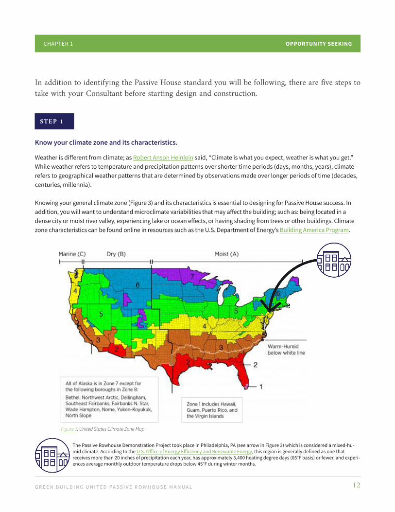
As you can see in Figure 11, our Demonstration Project’s ABRL highlighted the joist pockets in the party wall as a source of air leakage. We went over several possible paths during the design phase, including: setting the air barrier to the inside of the party wall and insulating the wall with mineral wool; setting the air barrier to the inside of the drywall and insulating with mineral wool; or setting the air barrier to the inside of the party
wall with no insulation. In the end, the air barrier was set to the inside of the party wall and we decided to air seal the joist pockets (and all of the other miscellaneous cracks and penetrations), but to not insulate the shared portion of the walls.
Although it can take significant work, air sealing the joist pockets not only reduces airflow, it reduces fire penetration risk and unwanted odor pollution, thereby improving air quality, livability, comfort, and safety. Deciding to forgo insulation saves a significant expense that can be used elsewhere in the project, but noise pollution may still be an issue.
Make a Mock-upConstructability requires hands-on education and training to ensure that materials are installed properly, appropriate techniques are used, and tasks and end goals are understood by the entire
Existing Masonry Wall
Fluid Applied Air Barrier at Masonry
Joist Pockets
Existing Floor Sheathing Cut Back from Wall to Pro-vide Access to Floor Joists
the roof. Our team chose the ceiling as the air barrier because it avoided having to rebuild the parapet walls and the front cornice with airtight construction. Before making this decision, we also considered placing the air barrier between the joists and the ceiling drywall, and just above the joists. By keeping it simple, labor and materials were reduced and the end goal achieved. We decided not to install recessed lights in the ceiling to avoid breaking the air barrier.
Know the Optimal Solution May be a Shared One Most rowhouses share at least some of their walls with neighboring buildings (known as party walls). As discussed in Chapter 2: Building Enclosures, a party wall that abuts another occupied rowhouse is adiabatic. Because of this, the wall needs to be air sealed but not necessarily insulated for temperature comfort.
Figure 11: Party Wall Joist Pockets

G R E E N B U I L D I N G U N I T E D PA S S I V E R O W H O U S E M A N U A L 26
CONNECTIONSCHAPTER 3
team. For some locations, like the roof-to-wall connection (which may include detailing several wall plane changes at the parapet), the team should construct a mock-up that everyone can study and practice with before tackling the roof line.
Utilize an Energy Model This can be used as a tool to test solution scenarios (as previously noted, we used WUFI in the Demonstration Project). Utilize Dynamic Hygrothermal AnalysisThis allows you to measure and understand the movement of heat and moisture through your proposed connection solutions to obtain predictions of performance to identify the best assemblies.
Section 3: Conclusion
Because connections can compromise the airtight envelope needed for a successful project, paying attention to them is one of the most essential elements when retrofitting a rowhouse. Working collaboratively with your Passive House Consultant and bringing the Passive House Rater in early are key in the planning and design stages. Ensure that everyone on the team understands the importance of the ABRL, adhere to rigorous quality control standards, and implement continuous education on the construction site so the rowhouse will be built as designed.
With your ABRL in place and a solid understanding of how all the components of your project relate, it is time for Chapter 4, where we provide guidance for evaluating and selecting Materials.

G R E E N B U I L D I N G U N I T E D PA S S I V E R O W H O U S E M A N U A L 27
Section 1: Overview
Now that you have set the air barrier, located penetrations and thermal bridge locations, and identified all the air sealing challenges, it is time to explore the materials needed to achieve an airtight and vapor permeable building. The Passive House standard does not require the use of specific materials, so in lieu of providing an expansive list of materials options, we will spend this chapter sharing best practices for materials selection.
Think of Passive House like a great thermos; put something hot or cold in a thermos and it stays that way for an extended period. Understanding the performance criteria of materials needed in each control layer (see Chapter 2: Building Enclosures) will help ensure your “thermos” delivers the highest performance possible. Note that the connections among materials are equally important as the materials themselves, so we encourage you to reference this chapter in tandem with Chapter 3: Connections.
We also recommend that you factor in the health and carbon impacts of materials, as we will briefly discuss in this chapter.
Materials
C H A P T E R 4

G R E E N B U I L D I N G U N I T E D PA S S I V E R O W H O U S E M A N U A L 28
MATERIALSCHAPTER 4
Cavity
Framing
Cavity
R-value2.0015.000.4617.46
Framing
R-value2.004.940.467.40
Component8.0” Brick (R0.25 per inch)3.5” Fiberglass Insulation (R15)0.5” Gypsum wallboard (R0.91 per inch)Total R
Component8.0” Brick (R0.25 per inch)3.5” Wood Stud (R1.41 per inch)0.5” Gypsum wallboard (R0.91 per inch)Total R
Figure 12: Effective R-value Calculation
Effective R-value
As you can see in Figure 12, effective R-value is often a more useful value as it represents the cumulative value of thermal resistance for all materials within an assembly. In the case of a wall assembly, it would account for the insulation of the studs and exterior and interior finishes as well as the insulation placed between the studs.
U-value
U-value is the reciprocal of R-value (1/R-value). It is a measure of the rate of heat transfer through a material and is especially pertinent in evaluating window performance. The smaller the value the slower the rate of transfer.
Section 2: Strategies
Know Your TerminologyYour Passive House Consultant will employ several terms to define performance. There are three worth noting: R-value, U-value, and Perm.
R-value
R (or Resistance) is a measure of how well a material resists the flow of heat. Nominal R-value (what is on the label) takes into account the thermal resistance of a material. In the case of insulation, it would be the insulation placed between the studs. The higher the value the more resistant the material or assembly.
G R E E N B U I L D I N G U N I T E D PA S S I V E R O W H O U S E M A N U A L 29
Perm
Perm, or permeability, is the rate at which air, gasses, and vapor pass through a membrane. We are primarily concerned with the movement of vapor through - or getting trapped - within wall assemblies where it can condense within the structure. Consequently, perm values are primarily applied to vapor retarders. Very low permeability vapor retarders (Class I) are rated at 0.1 perms or less. Low permeability vapor retarders (Class II) are rated at greater than 0.1 perms and less than or equal to 1.0 perms. Medium permeability vapor retarders (Class III) are rated at greater than 1.0 perms and less than or equal to 10 perms.
In the case of a Passive House, the goal is to have an airtight membrane (near zero air permeance) that may or may not allow vapor to pass through. Depending upon the application, you may want a vapor open or vapor closed membrane to allow any moisture to move through a wall assembly. In most Passive House wall assemblies, the air barriers are vapor open to mitigate the condensation of vapor laden air.
Materials Selection Starts Once the ABRL Plan is SetYour Passive House Consultant will work with you to develop plans and details for the location and performance of the weather barrier, insulation, and air barrier, and identify air sealing requirements. While your team selects materials, look for optimization, including applicability to as-built conditions, performance goals, and budget. While Passive House performance is usually measured by the R-value, U-value, and Perm, there are several other factors to keep in mind:
Air control is more important than thermal control.
If an assembly is airtight, bulk water and wind cannot move through it. Selected air barrier materials should be: • Impermeable to air flow• Continuous over the entire building enclosure• Able to withstand the forces that may act on them during and after construction• Durable over the expected lifetime of the building
Make sure your materials are compatible.
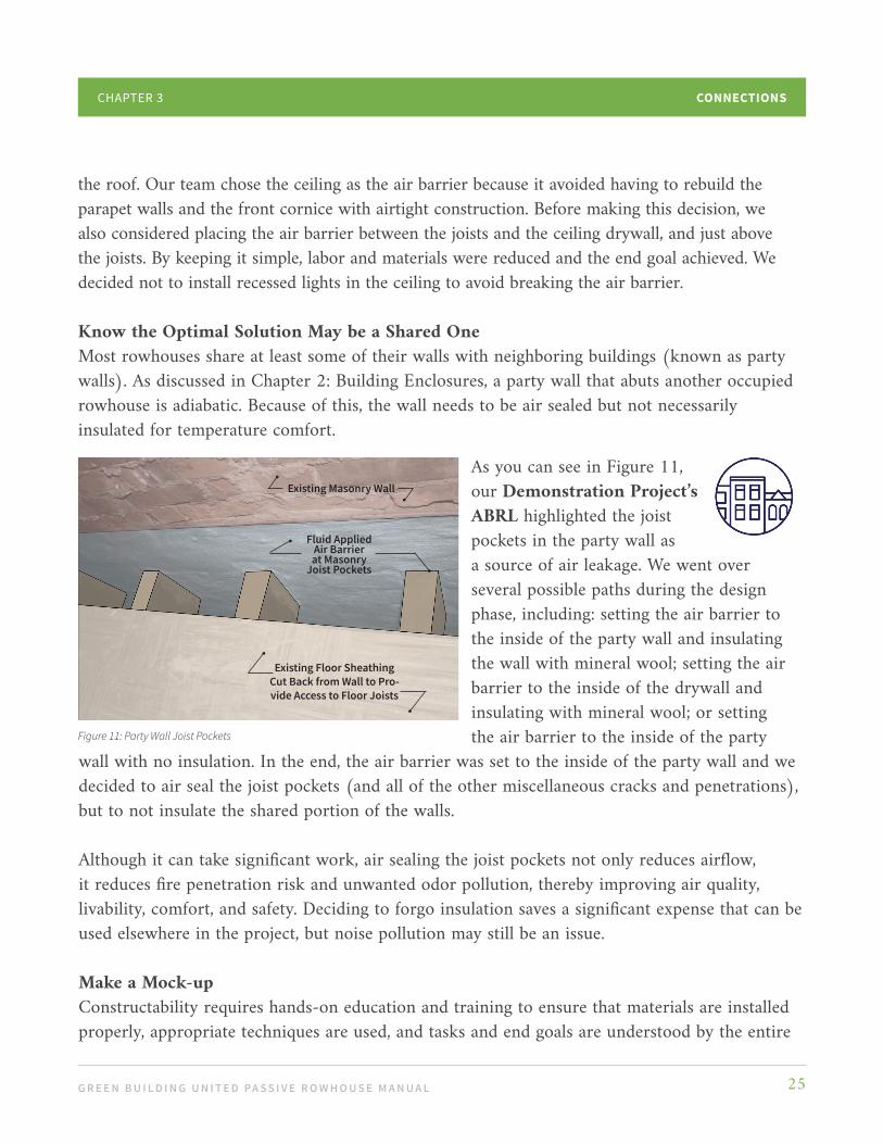
Weather and air barriers are membranes that often rely on tape or liquid applied products to be continuous, particularly at transitions and penetrations (membrane edges and openings). When you transition from one control layer material to an adjacent one (e.g., at a penetration or a window/door opening), the connections between the two must be durable enough to last the expected lifetime of both materials. In other words, make sure the materials you select are intentionally designed to go together; do not randomly mix and match.
To that end, many air sealing components are designed to be used as a system, so elements from different systems and manufacturers may be incompatible.
MATERIALSCHAPTER 4

G R E E N B U I L D I N G U N I T E D PA S S I V E R O W H O U S E M A N U A L 30
MATERIALSCHAPTER 4
Material Selection Has Significant Health and Carbon Implications These two points are increasing in public awareness and are important to consider when developing the Owner’s Project Requirements (see Chapter 1: Opportunity Seeking).
A NOTE ABOUT HEALTH AND CARBON
A material’s embodied carbon (or carbon created during product manufacturing) directly contributes to climate change. This can be difficult to identify, but by requesting low-to-zero embodied carbon products, you can influence how manufacturers and suppliers operate and reduce the built environment’s carbon footprint. MaterialsCAN is a group of manufacturers that prioritizes reducing embodied carbon in building materials, providing information you can use to select low carbon materials.
Materials may also contain ingredients that are harmful or potentially harmful to living beings. Opting for safer materials will help ensure the health and wellbeing of rowhouse occupants. Many manufacturers have released health and material trans-parency documentation for their products. For example, products with Declare Labels that are certified “Red List Free” meet stringent requirements and demonstrate that they contain no chemicals or elements known to pose serious human health and larger ecosystem risks. Additionally, when inherently non-emitting (low or no VOC) materials cannot be used, products that demonstrate compliance with California Department of Public Health (CDPH) Standard Method for VOC Emissions can be prioritized to limit contaminant emissions indoors and promote better indoor air quality.
Material Selection and Application Has Budget ImplicationsAs we discussed in earlier chapters, maintaining the air barrier is critical to project success. Once you move from the paper plan to the field, discovered and/or existing conditions may change the way air barrier continuity is maintained and insulation installed. If changes are needed, redraw
the various options under consideration in detail, identifying the control layers and materials so you can understand the performance of each vis-a-vis the cost.

G R E E N B U I L D I N G U N I T E D PA S S I V E R O W H O U S E M A N U A L 31
MATERIALSCHAPTER 4
As we learned from the Demonstration Project...
In the case of the party wall (Figure 13), examine several different solutions to achieve the end goal of budget friendly high performance. One way to achieve this is to not demolish a wall if it is in good shape (shown by wall paper in Figure 13). In the Demonstration Project, we contemplated various air barrier and taping solutions before selecting Option 3 (below), a liquid applied air barrier with high performance caulk for wall deformities and joist pockets.
We opted to not insulate the party wall, which provided superior performance at a slight price premium.
OPTION 1 OPTION 2 OPTION 3
Air Membrane Liquid Sealer Parge and Liquid SealerCaulk Major Holes Caulk Major Holes Caulk Major HolesTape Joist Pockets Tape Joist Pockets Caulk Joist Pockets
Material $$ $$$ $$Labor $$$ $$$ $$Costs $$$ $$$ $$Performance + + ++
Liquid Sealer
Existing Wall Paper
Figure 13: Party Wall Existing Condition
$ lowest cost $$ moderate cost $$$ highest cost + lowest performance ++ moderate performance +++ best performance

G R E E N B U I L D I N G U N I T E D PA S S I V E R O W H O U S E M A N U A L 32
MATERIALSCHAPTER 4
In the case of the complicated parapet-roof-wall intersection (Figure 14), our Demonstration Project team thought of various ways to achieve superior insulation while optimizing the labor and materials required to perfectly air seal the parapet framing. The air barrier was placed at the roof level, the parapet was sealed with a liquid membrane, and the ceiling void was insulated
OPTION 1 OPTION 2 OPTION 3
Tape All Framing Connections Tape Roof to Wall Intersection Liquid SealerRigid Insulation-Soffit and Roof Rigid Insulation at Roof Line Rigid Insulation-Soffit and RoofSuper Insulate Roof w/ Blown-in cellulose
--- Super Insulate Roof w/ Blown in cellulose
Drywall Under Roof Drywall Under Roof Drywall Under Ceiling Joists
Material $$ $$$ $$Labor $$$ $$$ $$Costs $$$ $ $$Performance ++ + ++
with blown in cellulose. Although expected performance was slightly less than the perfect soffit sealing of Option 1 (below), the reduced cost with good performance of Option 3 was selected.
Continuous Air Barrier Over Roof Insulation
Ledger
Drywall Ceiling
Service Cavity/SoffitBetween Ceiling and RoofContinuous Air Barrier
at Exterior Wall
Framing for Drywall Ceiling Ledger
$ lowest cost $$ moderate cost $$$ highest cost + lowest performance ++ moderate performance +++ best performance
Figure 14: Parapet-Roof-Wall Intersection
G R E E N B U I L D I N G U N I T E D PA S S I V E R O W H O U S E M A N U A L 33
MATERIALSCHAPTER 4
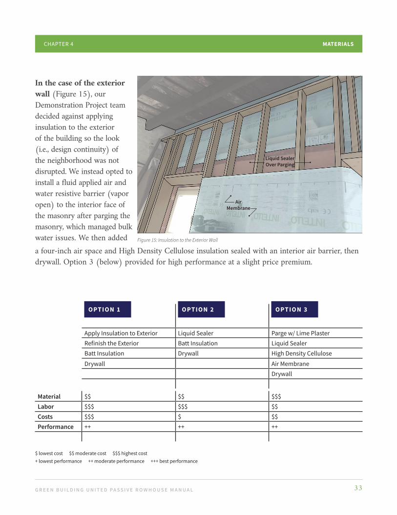
In the case of the exterior wall (Figure 15), our Demonstration Project team decided against applying insulation to the exterior of the building so the look (i.e., design continuity) of the neighborhood was not disrupted. We instead opted to install a fluid applied air and water resistive barrier (vapor open) to the interior face of the masonry after parging the masonry, which managed bulk water issues. We then added
OPTION 1 OPTION 2 OPTION 3
Apply Insulation to Exterior Liquid Sealer Parge w/ Lime PlasterRefinish the Exterior Batt Insulation Liquid SealerBatt Insulation Drywall High Density Cellulose
Drywall Air MembraneDrywall
Material $$ $$ $$$Labor $$$ $$$ $$Costs $$$ $ $$Performance ++ ++ ++
a four-inch air space and High Density Cellulose insulation sealed with an interior air barrier, then drywall. Option 3 (below) provided for high performance at a slight price premium.
Liquid SealerOver Parging
Air Membrane
Figure 15: Insulation to the Exterior Wall
$ lowest cost $$ moderate cost $$$ highest cost + lowest performance ++ moderate performance +++ best performance

G R E E N B U I L D I N G U N I T E D PA S S I V E R O W H O U S E M A N U A L 34
MATERIALSCHAPTER 4
Section 3: Conclusion
There are numerous materials on the market with varying quality, providing an array of options for achieving your goals. Focusing on the air barrier, desired performance, and budget will simplify materials selections for your project.
It is critical that you check for material compatibility. Randomly mixing and matching may not be feasible, or may result in incongruent life spans of adjacent materials. Make sure to explore the many companies that provide information on material options, where you can source them, and the relative performance aspects of each. You may also wish to focus on selecting materials that are healthier for occupants and/or have lower carbon footprints.
Next you will want to hone in on two materials that greatly impact airtightness and energy performance: Windows and Doors.

G R E E N B U I L D I N G U N I T E D PA S S I V E R O W H O U S E M A N U A L 35
Section 1: Overview
Windows and doors are fundamental elements of the home. They keep out rain, wind, cold and heat, while providing light, comfort, health, and wellbeing. For Passive House certification, windows and doors have a category of their own - they are that important.
Passive House units are high performing products that reduce or eliminate drafts, condensation, and moisture - which are sources of mold, mildew, and rot. They also play an aesthetic role and are seen and touched daily, creating opportunities for window seats and connections to light, air, and views. They provide landings for plants and decorative items, and reduce sound pollution by being nearly soundproof.
To make the best investment for the building and the most successful decisions for Passive House certification, the units and their installations must be taken into account. As always, work with your entire design team during selections and use the questions and tips in this chapter to guide your decisions.
Windows + Doors
C H A P T E R 5
G R E E N B U I L D I N G U N I T E D PA S S I V E R O W H O U S E M A N U A L 36
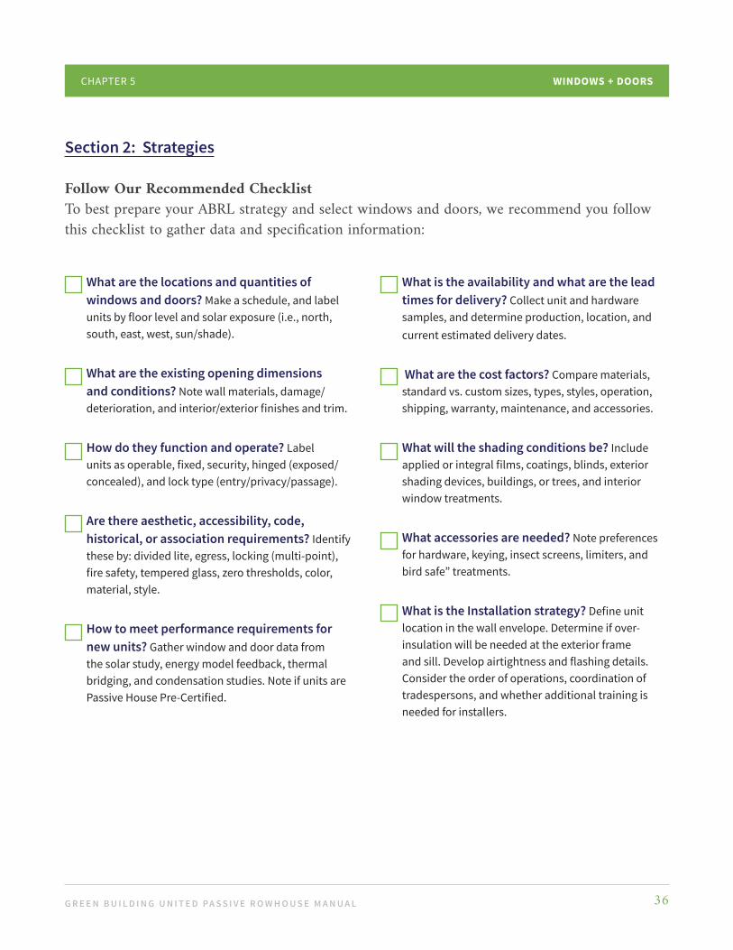
1. What are the locations and quantities of windows and doors? Make a schedule, and label units by floor level and solar exposure (i.e., north, south, east, west, sun/shade).
2. What are the existing opening dimensions and conditions? Note wall materials, damage/deterioration, and interior/exterior finishes and trim.
3. How do they function and operate? Label units as operable, fixed, security, hinged (exposed/concealed), and lock type (entry/privacy/passage).
4. Are there aesthetic, accessibility, code, historical, or association requirements? Identify these by: divided lite, egress, locking (multi-point), fire safety, tempered glass, zero thresholds, color, material, style.
5. How to meet performance requirements for new units? Gather window and door data from the solar study, energy model feedback, thermal bridging, and condensation studies. Note if units are Passive House Pre-Certified.
WINDOWS + DOORSCHAPTER 5
Section 2: Strategies
Follow Our Recommended ChecklistTo best prepare your ABRL strategy and select windows and doors, we recommend you follow this checklist to gather data and specification information:
6. What is the availability and what are the lead times for delivery? Collect unit and hardware samples, and determine production, location, and current estimated delivery dates.
7. What are the cost factors? Compare materials, standard vs. custom sizes, types, styles, operation, shipping, warranty, maintenance, and accessories.
8. What will the shading conditions be? Include applied or integral films, coatings, blinds, exterior shading devices, buildings, or trees, and interior window treatments.
9. What accessories are needed? Note preferences for hardware, keying, insect screens, limiters, and bird safe” treatments.
10. What is the Installation strategy? Define unit location in the wall envelope. Determine if over-insulation will be needed at the exterior frame and sill. Develop airtightness and flashing details. Consider the order of operations, coordination of tradespersons, and whether additional training is needed for installers.

G R E E N B U I L D I N G U N I T E D PA S S I V E R O W H O U S E M A N U A L 37
WINDOWS + DOORSCHAPTER 5
Perform Our Recommended Prep Steps
STE P 1
Do exploratory demolition.
Determine your rough opening and existing conditions for doors and windows. In order to refine the details and order properly sized windows, identify and plan for window weight pockets, deteriorated framing, and sill conditions. Investigate threshold conditions by being aware of thresholds heights, air leakage, and thermal bridging. Some manufacturers offer low profile or zero thresholds to resolve difficult conditions, accessibility, and aesthetic requirements; note that some need special installation into the sub floor. Knowing the existing conditions beforehand will make detailing easier and more successful.
STE P 2
Review the installation details with the team.
Discuss design, installation, and air sealing with the entire design team (Architect, Passive House Consultant, Energy Modeler, Contractor, and Air Boss).
STEP 3
Expose the entire original rough opening.
Remove all existing storms, sashes, weights/springs, brick mold, and trim.
STEP 4
Make a mock-up and do a trial run.
Make a mock-up and do a trial run. Use the first window and door installations as a dry run and test them before installing all the units.
G R E E N B U I L D I N G U N I T E D PA S S I V E R O W H O U S E M A N U A L 38
WINDOWS + DOORSCHAPTER 5
Function Function
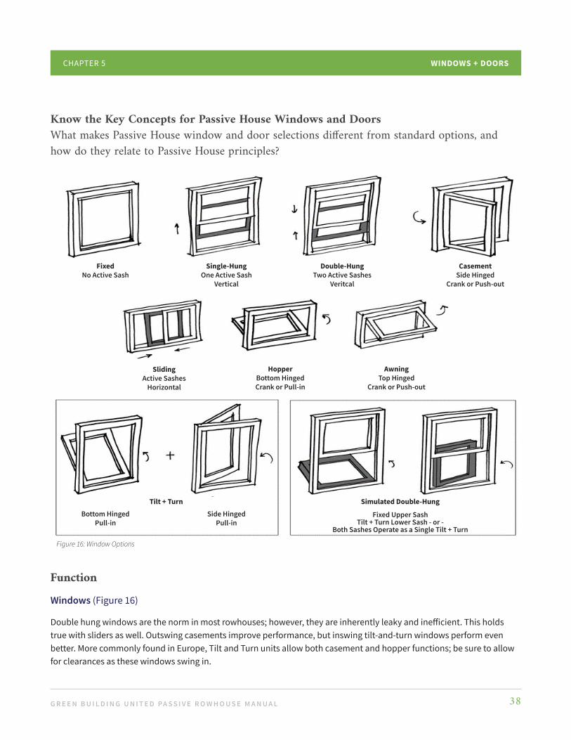
Windows (Figure 16)
Double hung windows are the norm in most rowhouses; however, they are inherently leaky and inefficient. This holds true with sliders as well. Outswing casements improve performance, but inswing tilt-and-turn windows perform even better. More commonly found in Europe, Tilt and Turn units allow both casement and hopper functions; be sure to allow for clearances as these windows swing in.
FixedNo Active Sash
Side HingedPull-in
Bottom HingedPull-in
AwningTop Hinged
Crank or Push-out
HopperBottom HingedCrank or Pull-in
SlidingActive Sashes
Horizontal
CasementSide Hinged
Crank or Push-out
Double-HungTwo Active Sashes
Veritcal
Single-HungOne Active Sash
Vertical
Tilt + Turn Simulated Double-Hung
Fixed Upper SashTilt + Turn Lower Sash - or -
Both Sashes Operate as a Single Tilt + Turn
Know the Key Concepts for Passive House Windows and DoorsWhat makes Passive House window and door selections different from standard options, and how do they relate to Passive House principles?
Figure 16: Window Options

G R E E N B U I L D I N G U N I T E D PA S S I V E R O W H O U S E M A N U A L 39
WINDOWS + DOORSCHAPTER 5
Fixed windows provide the highest thermal and airtight performance and are also the least expensive. By contrast, every active window creates the need. Every active sash creates a need for additional gaskets, hardware, manufacturing, and often screens, limiters, and locks.
• Consider where ventilation and emergency egresses are required or desired and select appropriately.
• For historically designated properties or aesthetic reasons, simulated double-hung units offer a high performance solution. The sashes are offset to create the appearance of a traditional double hung unit.
Doors
Passive House doors are typically hinged or lift-and-slide for larger openings. Lift-and-slide units are sliding doors that lift up during operation, and lock down again for a great air seal when closed. Note that full lite/all glass doors are often more efficient and surprisingly less expensive than opaque doors.
AnatomyAnatomy Passive House windows (Figure 17) and doors (Figure 18) for most U.S. climate zones are triple pane. Most units also have insulated frames with multiple air sealing gaskets and “warm edge” spacers between the glass. As a result, frames are often wider and thicker.
Exterior Cladding
Airtight Gaskets
Triple Glazing (3 layers of glass)
Insulating Gas Between Glass Layers (Argon Krypton)
Warm Edge Spacers Between Glass Layers
Insulated Frame
Insulated Frame• Wood• Fiberglass• Aluminum• UPVC• PVC
Door Handle TurnsWheel Lever TurnsWheel DropsDoor Lifts + SlidesGaskets Seal
When Door Drops
Note: • In smaller units, wider frames disproportionately reduce the daylight area.• A few exceptions use a film in lieu of a middle pane, allowing for leaner frames.• Locks and handles often operate in a non-traditional manner (e.g. European vs. U.S.), so know before
you purchase. Other limiting issues include re-keying, keying alike, master keying, emergency egress, door closers, and fire ratings.
Figure 17: Passive House Tilt + Turn Window Figure 18: Passive House Lift + Slide Door

G R E E N B U I L D I N G U N I T E D PA S S I V E R O W H O U S E M A N U A L 40
WINDOWS + DOORSCHAPTER 5
Performance Criteria There are several performance measures used for all units.
U-value (lower is better)
As discussed in Chapter 2: Building Enclosures, envelope performance includes window and door calculations; therefore, adjusting U-values allows for balancing insulation elsewhere. The addition of “insulating gas” between glass panes increases performance.
Passive House Triple Glazed vs. Energy Star Double Glazed:
• Passive House range: U 0.11 to U 0.20 (R-9 to R-5)• Energy Star range: U 0.25 to U 0.35 (R-4 to to R-2.8)
Door U-values are not as low as windows. They typically have more frame components (stiles and rails) with higher Door U-values are not as low as windows. They typically have more frame components (stiles and rails) with higher U-values, because they are not insulated. Look for U-values at or below U 0.89 (R-1.12). U-values, because they are not insulated. Look for U-values at or below U 0.89 (R-1.12).
Solar Heat Gain Coefficient (SHGC) and Visible Transmittance (VT)
These values define the amount of light (ultraviolet, or UV) and heat (solar gain) that passes through the glazing. Applied coatings enhance performance.
• SHGC: The standard U.S. practice for controlling summer heat gain is to reduce the SHGC with low emissivity (low-E) coatings, films, frosting and fritting. However, this prevents the free winter solar gains needed to meet Passive House goals. Typical Passive House SHGCs range from 0.45 to 0.60, and a good rule is to stay above 0.50.
• VT: Coatings also affect VT, the measure of how much light transmits through the glass. Higher VT increases daylighting and influences electric lighting usage as well as occupant comfort and well being. Consider higher VT ranges between 0 and 1.

G R E E N B U I L D I N G U N I T E D PA S S I V E R O W H O U S E M A N U A L 41
WINDOWS + DOORSCHAPTER 5
Pre-CertificationBoth PHI and PHIUS offer database resources for Passive House Pre-Certified units. Pre-Certified units are not required for Passive House certification, but they do offer tested and verified performance criteria, and labeling input for WUFI and PHPP models, making energy modeling much easier.
The PHIUS Verified Window Performance Data Program is categorized by climate zone and lists manufacturers and models with U-value and SHGC data (Figure 19).
The PHI Component Database is searchable by climate zone, country of origin, manufacturer, material, and efficiency performance data for input to your WUFI or PHPP models.
LocationGlazing, selection, location, and size can have drastic effects on the HVAC system (see Chapter 7: Heating + Cooling Systems for more information). Existing door and window openings are usually retained in a retrofit, and therefore have predetermined sizes and orientations. Blocking in a window, adding or enlarging an opening, or installing skylights can improve the energy balance, comfort, and daylighting.
Optimize Heat GainOptimizing heat gain in winter while controlling or shading it in summer involves several tactics.
Orientation
Orientation governs which tactics are most effective. Northern windows do not require shading. Southern windows are easier to shade in the summer and shoulder months with straightforward awnings, whereas the angle of the sun in east and west orientations makes controlling solar gains more difficult. Side fins, sliding shutters, and other types of baffling are options for non-south orientations. Natural shading from deciduous trees, arbors, and vines can offer great summer shading while allowing winter solar warming.
Figure 19: PHIUS Verified Window Performance Data Program
G R E E N B U I L D I N G U N I T E D PA S S I V E R O W H O U S E M A N U A L 42
WINDOWS + DOORSCHAPTER 5
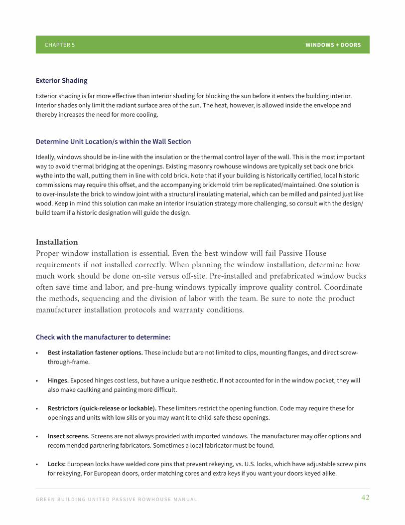
Exterior Shading
Exterior shading is far more effective than interior shading for blocking the sun before it enters the building interior. Interior shades only limit the radiant surface area of the sun. The heat, however, is allowed inside the envelope and thereby increases the need for more cooling.
Determine Unit Location/s within the Wall Section
Ideally, windows should be in-line with the insulation or the thermal control layer of the wall. This is the most important way to avoid thermal bridging at the openings. Existing masonry rowhouse windows are typically set back one brick wythe into the wall, putting them in line with cold brick. Note that if your building is historically certified, local historic commissions may require this offset, and the accompanying brickmold trim be replicated/maintained. One solution is to over-insulate the brick to window joint with a structural insulating material, which can be milled and painted just like wood. Keep in mind this solution can make an interior insulation strategy more challenging, so consult with the design/build team if a historic designation will guide the design.
InstallationProper window installation is essential. Even the best window will fail Passive House requirements if not installed correctly. When planning the window installation, determine how much work should be done on-site versus off-site. Pre-installed and prefabricated window bucks often save time and labor, and pre-hung windows typically improve quality control. Coordinate the methods, sequencing and the division of labor with the team. Be sure to note the product manufacturer installation protocols and warranty conditions.
Check with the manufacturer to determine:
• Best installation fastener options. These include but are not limited to clips, mounting flanges, and direct screw-through-frame.
• Hinges. Exposed hinges cost less, but have a unique aesthetic. If not accounted for in the window pocket, they will also make caulking and painting more difficult.
• Restrictors (quick-release or lockable). These limiters restrict the opening function. Code may require these for openings and units with low sills or you may want it to child-safe these openings.
• Insect screens. Screens are not always provided with imported windows. The manufacturer may offer options and recommended partnering fabricators. Sometimes a local fabricator must be found.
• Locks: European locks have welded core pins that prevent rekeying, vs. U.S. locks, which have adjustable screw pins for rekeying. For European doors, order matching cores and extra keys if you want your doors keyed alike.
G R E E N B U I L D I N G U N I T E D PA S S I V E R O W H O U S E M A N U A L 43
WINDOWS + DOORSCHAPTER 5
Maintain the ABRL
Plan continuous air barrier connections and thermal continuity. Avoid thermal bridging by insulating around the pocket and over insulating the exterior frame. Consider expanding tapes and structural insulation products to improve aesthetics, lessen labor, and improve results.
Optimize Location and Connection
Work with your team and Consultant to optimize the location and connections with the air barrier and thermal barriers using WUFI Hygrothermal modeling. Please note this modeling is often an additional service and may or may not be required for certification.
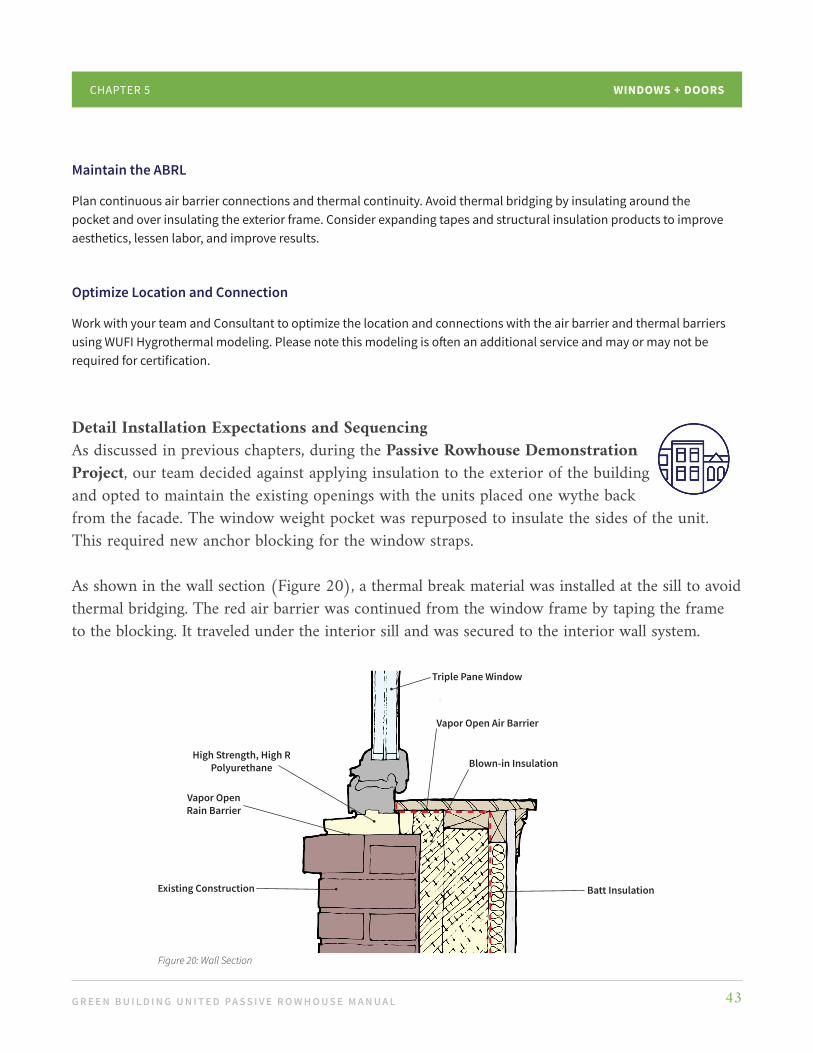
Detail Installation Expectations and SequencingAs discussed in previous chapters, during the Passive Rowhouse Demonstration Project, our team decided against applying insulation to the exterior of the building and opted to maintain the existing openings with the units placed one wythe back from the facade. The window weight pocket was repurposed to insulate the sides of the unit. This required new anchor blocking for the window straps.
As shown in the wall section (Figure 20), a thermal break material was installed at the sill to avoid thermal bridging. The red air barrier was continued from the window frame by taping the frame to the blocking. It traveled under the interior sill and was secured to the interior wall system.
Triple Pane Window
Blown-in Insulation
Vapor Open Air Barrier
High Strength, High RPolyurethane
Vapor OpenRain Barrier
Existing Construction Batt Insulation
Figure 20: Wall Section

G R E E N B U I L D I N G U N I T E D PA S S I V E R O W H O U S E M A N U A L 44
WINDOWS + DOORSCHAPTER 5
In the plan detail (Figure 21), the red air barrier extends from the wall over the window flashing to connect to the window. The interior side of the brick wall was air sealed by parging. Expanding foam tape was used to seal and insulate gaps around the sides and top of the window and frame.
Note: Thicker super-insulated walls often result in deep window pockets (holes in the ground for basement windows) that reduce light. In this example, the team decided to angle the jamb (as shown above). This is a good tactic for increasing light into the room.
Section 3: Conclusion
Once questions are answered and existing conditions and constraints are evaluated, think about how openings integrate with the overall wall assembly. The entire construction team should be aware of project goals and trained on installation techniques. Ideally, the contractor is engaged early to weigh in on constructability, sequencing of the work, and to provide preliminary cost estimates. Providing a team kick-off meeting is a great way to get complete team buy-in, as is a training around a mock-up window for reviewing and testing.
Lastly, be sure to dedicate one team member as the Air Boss. This person is responsible for quality control, ongoing training, and communication between the owner, construction trades, and design teams.
Figure 21: Plan Detail
Existing Construction
Batt Insulation
Blown-in Insulation
Vapor Open Air Barrier
Triple Pane Window
Rigid Thermal Break Material
Painted Wood Trim

G R E E N B U I L D I N G U N I T E D PA S S I V E R O W H O U S E M A N U A L 45
WINDOWS + DOORSCHAPTER 5
ADDITIONAL RESOURCES
Designing & Selecting Windows & Doors for Passive House
by Bronwyn Barry
Windows in a Step-By-Step Retrofit
by Passivhaus Institute
Can Highly Glazed Building Facades be Green?
by John Straube
Window Blinds Dealer Locator
by MHZ
With Passive House window and door decisions in place, the project team can move on to the next element of high performance buildings: Energy.

G R E E N B U I L D I N G U N I T E D PA S S I V E R O W H O U S E M A N U A L 46
Section 1: Overview
Passive Rowhouses use energy in a similar way to other types of Passive Houses, in that the major use will be domestic hot water generation followed by the HVAC system. Lighting, appliances, and plug loads will make up the remainder. Retrofitting to the Passive House standard and using water efficient plumbing fixtures will greatly reduce energy demand for generating domestic hot water, HVAC, and lighting. How that energy is generated and sourced must also be considered. Generally, in the regions where rowhouses are prevalent, the two utility options are electricity and natural gas. As discussed in the Manual’s Introduction, addressing the built environment’s climate
Energy
C H A P T E R 6
impact means reducing carbon emissions at the source, so we exclusively advocate for using electricity as the energy source, which can be powered by renewable technologies such as wind and solar. This does not mean a Passive House cannot use fossil fuels; however, all of our advice concerning building systems will be focused on electrification. As mentioned in Chapter 3: Connections, the optimal solution for a rowhouse may be a shared solution. The shared walls may mean transmission of noxious noises and aromas, but there are benefits to reap from shared heating and cooling. Because rowhouses have a relatively small amount of area exposed to the exterior climate, and have significant wall area protected (as shared party walls), the amount of heat loss and gain is limited (Figure 22).
Party WallAdibiatic
Heat Loss (surfaces)
Heat Loss (surfaces)
Heat Loss (surfaces)
Heat Loss (surfaces)
Where to cite this
Figure 22: Rowhouse Heat Loss

G R E E N B U I L D I N G U N I T E D PA S S I V E R O W H O U S E M A N U A L 47
ENERGYCHAPTER 6
Chapter 7: Heating + Cooling will discuss how this impacts HVAC systems selection, but for now, focus on the fact that from an energy standpoint, the typical rowhouse has a few unique advantages and disadvantages:
ADVANTAGES
• Party walls share heating and cooling which allows for a reduction in HVAC equipment sizing and energy consumption.
• Depending on their location in the city, many rowhouses are shaded by adjacent structures or large street trees, which can help reduce unwanted solar gains.
• Due to their vertically oriented nature, rowhouses contain a great deal of volume of livable space per area of external envelope and footprint.
DISADVANTAGES
• Rowhouses may be locked into unfavorable orientations, making it impossible for active siting of the rowhouse to take advantage of solar heat gains.
• Rowhouses often have very limited roof area for mounting solar PV systems.
To achieve Passive House certification under PHIUS+, all buildings in a similar climate zone, rowhouse or not, are held to the same metric. As previously noted, our Demonstration Project took place in Philadelphia, PA. This is in ASHRAE Climate Zone 4A where the metrics are: • 4.5 kbtu/SF - Annual Heating Demand• 4.2 btu/ SF - Peak Heating Load• 5.4 kbtu/ SF - Annual Cooling Demand• 4.7 btu/ SF - Peak Cooling Load• 6.7 btu/ SF - Manual J Peak Cooling Load
Typical rowhouse energy use intensity (EUI) in Philadelphia is 63 kBtu/sf/yr. While the Mid-Atlantic region is a heating dominated climate, hot and humid summers increase cooling energy consumption in many Passive Rowhouses because of the need to manage humidity. Keep these energy drivers in mind during building design and construction.
G R E E N B U I L D I N G U N I T E D PA S S I V E R O W H O U S E M A N U A L 48
ENERGYCHAPTER 6
Section 2: Strategies
There are several energy system approaches you can take when retrofitting your rowhouse, as highlighted below. Optimize Air Sealing and Insulation of the Roof, Walls, and SlabThis reduces energy demand and creates a clear path to achieve Net Zero Energy while ensuring a healthy, comfortable, and resilient home. As previously shared, we used WUFI Passive energy modeling to guide decisions about air barrier location and insulation. Models like this will allow you to calculate optimal energy use, serving as a reference goal during verification testing.
Take Advantage of Party WallsFrom an energy perspective, the ideal rowhouse will be in the middle of the block so it shares energy with both neighbors, reducing the consumption of all three structures. If your rowhouse is adjacent to an open lot, this will need to be taken into account to ensure thermal comfort and energy efficiency (to compensate for no structure being connected to that side of the home). If there is a potential for a home or other structure to occupy the adjacent vacant lot in the future, factor in the influence this may have on the sizing and operation of the HVAC system and solar array (if applicable) to ensure its operation is not negatively affected.
Model Shared Party WallsWhile party walls are sealed to prevent the transfer of air and moisture, they are generally left uninsulated (or moderately insulated for noise purposes) and as such may transfer heat. This further reduces the sensible load on the HVAC system. The key is to design and install an HVAC system that handles microloads while still providing adequate dehumidification to avoid moisture problems, which will be discussed further in Chapter 7: Heating + Cooling. Model shared party walls as adiabatic to accurately reflect the operational condition of the home and avoid oversizing.
Be Intentional with Appliance Selection Select Energy Star and Watersense appliances that offer heat pump and induction technologies as well as those that eliminate the need for venting when possible (i.e., heat pump dryers). We also recommend oversizing PV by as much as 20% to account for degradation of modules over the life of the PV system.
Educate Your Team and Intended Rowhouse Occupants You will minimize total energy use by educating the collaborative team and occupants about

G R E E N B U I L D I N G U N I T E D PA S S I V E R O W H O U S E M A N U A L 49
ENERGYCHAPTER 6
hot water use, appliance maintenance, and plug loads. Throughout design and construction, the expected building HVAC use can be controlled; occupant demand and use once the project is complete is not controllable by the design team. To minimize total electric costs, the people that live in the rowhouse should evaluate their own usage, which may mean using cold water to wash clothes, turning off the lights when rooms
are unoccupied, and unplugging devices whenever possible to conserve energy.
Group/Place as North/West (as practical)
Roof Mounted PV Panels
Plumbing Vent
Mechanical Equipment
N
Skylights/Roof Structures
Figure 23: Options for Optimized Solar PV
Optimize Potential Solar Production through ModelingDeducting the expected kWh in solar production from the total anticipated whole building energy use from the energy model will provide a forecast of net energy use and utility costs. This should be performed with caution as individual occupant behavior will greatly influence the energy use of a Passive House, as may any future adjacent construction elements that shade panels.
Flat Mount Trellis (angled)Angled
Solar Panel Options
Roof Deck
Roof
Figure 24: Options for Optimized Solar PV
Optimize Roof Structure Location to Maximize Solar PV AccessIf solar is viable, this is one of the easiest design features to incorporate. To optimize the contiguous area available for solar PV installation (Figure 23), place design elements that may be located on the roof (e.g., ERV intake/exhaust, flue, plumbing vents, skylights) in a coordinated manner and as far north on the roof as practical to increase the amount of solar panels that can be placed on the roof. A consultation with a reputable solar company may be in order to help you identify which solar option is best for you (Figure 24).

G R E E N B U I L D I N G U N I T E D PA S S I V E R O W H O U S E M A N U A L 50
ENERGYCHAPTER 6
Plan for Solar During the Design ProcessPlanning during design will help reduce your installation cost and protect solar production potential. Pre-installing a one-inch conduit routed directly from the roof to the main service panel and preserving two breaker spaces in the lower right of the electrical panel will help assure safe interconnection while reducing penetrations through the outer shell and the need to run wire through finished spaces. Make sure to designate space on the wall near the electrical panel for the inverter and future battery installation.
Section 3: Conclusion
Energy consumption and climate change are inexorably linked, and one of the best methods of reducing greenhouse gas emissions is to reduce building energy use. Passive House is effective at achieving this reduction because it approaches the energy reduction strategy holistically - from the envelope outside to the systems inside. Adjacent undeveloped properties should be seriously considered when designing for HVAC and energy needs, as they may either hinder or help.
The two major sources of greenhouse gases in a Passive House are off-gassing from materials (such as spray foam) and refrigerant leaks from HVAC equipment. Passive Houses help reduce these risks by reducing the size of HVAC equipment required. Emissions are further reduced when occupants take steps to reduce their own electricity use. Every major component of a building is included when it comes to energy efficiency design in a Passive Rowhouse. Right sized mechanical systems that handle the unique heating, cooling, and dehumidification are key.
Addressing these energy loads and integrating HVAC into other systems, including ventilation and domestic hot water systems, will be discussed next in Chapters 7 and 8.

G R E E N B U I L D I N G U N I T E D PA S S I V E R O W H O U S E M A N U A L 51
Section 1: Overview
The climate of Philadelphia and many East Coast cities is characterized by relatively cold winters and hot humid summers. Climate zones 4A and 5A (of which Philadelphia and its surrounding counties are a part) have hot-humid climates. This requires the HVAC system to provide adequate heating while having dehumidification capacity. Retrofitting an existing rowhouse to meet Passive House standards entails an in-depth analysis of building mechanical system design. Monitoring progress as the systems are installed will help ensure that energy systems operate efficiently and as designed.
The beginning of any good Passive House design, whether new construction or retrofit, is the heating and cooling load calculation. This calculation should be performed when the building envelope areas and U-values are known, then refined as the design continues. As discussed in previous chapters, the Passive House envelope will greatly reduce heating and cooling loads due to outdoor conditions and infiltration through the envelope. It is not uncommon for Passive Houses to have cooling loads in the 1000-1200 sf/ton range. For reference, a typical code built home will have cooling loads in the 400-800 sf/ton range.
Passive House techniques also affect the internal loads as efficient Energy Star approved appliances are given preference, thus further reducing the internal sensible cooling loads. Passive House design also reduces latent cooling loads created through air infiltration through the envelope; however, occupants and processes (such as bathing, cooking, and occupant respiration) emit the same amount of moisture that would be found in a traditional house. The HVAC system must not only provide comfort during the hottest and coldest days of the year, but must also operate during off peak and shoulder seasons. During non-peak times (which naturally account for the majority of the time), the heat loss/heat gain through the envelope will be reduced even further, creating the microloads mentioned in the previous chapter. Design and install an HVAC system that handles these microloads while still providing adequate dehumidification to avoid moisture problems. The primary challenge in a Passive Rowhouse is the further reduction of sensible loads due to shared party walls.
Heating + Cooling
C H A P T E R 7
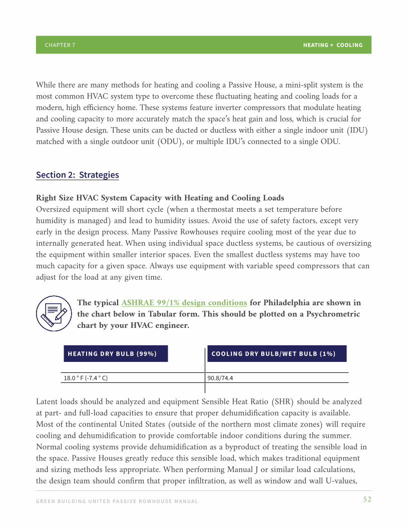
G R E E N B U I L D I N G U N I T E D PA S S I V E R O W H O U S E M A N U A L 52
HEATING + COOLINGCHAPTER 7
While there are many methods for heating and cooling a Passive House, a mini-split system is the most common HVAC system type to overcome these fluctuating heating and cooling loads for a modern, high efficiency home. These systems feature inverter compressors that modulate heating and cooling capacity to more accurately match the space’s heat gain and loss, which is crucial for Passive House design. These units can be ducted or ductless with either a single indoor unit (IDU) matched with a single outdoor unit (ODU), or multiple IDU’s connected to a single ODU.
Section 2: Strategies
Right Size HVAC System Capacity with Heating and Cooling LoadsOversized equipment will short cycle (when a thermostat meets a set temperature before humidity is managed) and lead to humidity issues. Avoid the use of safety factors, except very early in the design process. Many Passive Rowhouses require cooling most of the year due to internally generated heat. When using individual space ductless systems, be cautious of oversizing the equipment within smaller interior spaces. Even the smallest ductless systems may have too much capacity for a given space. Always use equipment with variable speed compressors that can adjust for the load at any given time.
Latent loads should be analyzed and equipment Sensible Heat Ratio (SHR) should be analyzed at part- and full-load capacities to ensure that proper dehumidification capacity is available. Most of the continental United States (outside of the northern most climate zones) will require cooling and dehumidification to provide comfortable indoor conditions during the summer. Normal cooling systems provide dehumidification as a byproduct of treating the sensible load in the space. Passive Houses greatly reduce this sensible load, which makes traditional equipment and sizing methods less appropriate. When performing Manual J or similar load calculations, the design team should confirm that proper infiltration, as well as window and wall U-values,
HE AT ING DRY BULB (99%) COOLING DRY BULB/WET BULB (1%)
18.0 ° F (-7.4 ° C) 90.8/74.4
The typical ASHRAE 99/1% design conditions for Philadelphia are shown in the chart below in Tabular form. This should be plotted on a Psychrometric chart by your HVAC engineer.
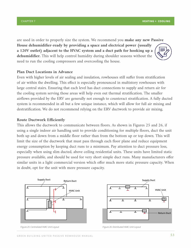
G R E E N B U I L D I N G U N I T E D PA S S I V E R O W H O U S E M A N U A L 53
HEATING + COOLINGCHAPTER 7
are used in order to properly size the system. We recommend you make any new Passive House dehumidifier-ready by providing a space and electrical power (usually a 120V outlet) adjacent to the HVAC system and a duct path for hooking up a dehumidifier. This will help control humidity during shoulder seasons without the need to run the cooling compressors and overcooling the house. Plan Duct Locations in AdvanceEven with higher levels of air sealing and insulation, rowhouses still suffer from stratification of air within the dwelling. This effect is especially pronounced in multistory rowhouses with large central stairs. Ensuring that each level has duct connections to supply and return air for the cooling system serving those areas will help even out thermal stratification. The smaller airflows provided by the ERV are generally not enough to counteract stratification. A fully ducted system is recommended in all but a few unique instance, which will allow for full air mixing and destratification. We do not recommend relying on the ERV ductwork to provide air mixing. Route Ductwork Efficiently This allows the ductwork to communicate between floors. As shown in Figures 25 and 26, if using a single indoor air handling unit to provide conditioning for multiple floors, duct the unit both up and down from a middle floor rather than from the bottom up or top down. This will limit the size of the ductwork that must pass through each floor plane and reduce equipment energy consumption by keeping duct runs to a minimum. Pay attention to duct pressure loss, especially when using slim ducted, above ceiling residential units. These units have limited static pressure available, and should be used for very short simple duct runs. Many manufacturers offer similar units in a light commercial version which offer much more static pressure capacity. When in doubt, opt for the unit with more pressure capacity.
Supply Duct Return Duct
HVAC Unit
Figure 25: Centralized HVAC Unit Layout
Supply Duct
HVAC Unit
Return Duct
Figure 26: Distributed HVAC Unit Layout

G R E E N B U I L D I N G U N I T E D PA S S I V E R O W H O U S E M A N U A L 54
HEATING + COOLINGCHAPTER 7
Recognize that Ductwork Leakage Manifests in Uneven Distribution of VentilationTest all ductwork, supply, and return for leakages prior to drywall installation, as it is difficult to fix leaking ducts after the fact. When using flexible ductwork, assure that the connections to the sheet metal ductwork, diffusers, and registers are sealed airtight, which are natural areas for duct leakage. Do not use panned joist or wall studs to act as return air system ductwork; this will not only provide a path for duct leakage, but also for untreated environmental air to enter the duct system uncontrolled.
Insulate Supply Ductwork to Prevent CondensationThis is not typically done in residential construction, but with such a tight envelope, we have found that ductwork above ceilings is subject to condensation issues.
Know that Condensate Drains MatterMake sure HVAC condensate drains are sized and installed properly. When using downflow HVAC units, moisture from the coil can easily flow into the ductwork below. Utilize the drain pan accessory and make sure it is installed correctly.
Monitor ProgressReview HVAC system installation as it progresses to assure that the contractor follows the design and has not missed any steps that would adversely affect system performance.
Pay Attention to the Outdoor Unit’s LocationIt is important to keep equipment out of winter snow accumulation. This will likely mean raising the outdoor heat pump unit at least 18” above grade or roof surfaces, which will ensure snow does not drift against the unit, or that ice builds up during the unit’s defrost cycle, negatively affecting unit performance. Also, maintain minimum manufacturer required clearances around outdoor equipment. When using multiple outdoor units make sure the exhaust air from one unit is not entering the supply side of another so the equipment’s capacity is not affected.
Install Equipment in Easily Accessible LocationsEasy access to filters is a must, particularly with HVAC equipment that may be installed in attics or small closets. The location of the mechanical equipment and its associated duct and piping runs should be given careful consideration, as the basement may not always be placed within the thermal envelope.

G R E E N B U I L D I N G U N I T E D PA S S I V E R O W H O U S E M A N U A L 55
HEATING + COOLINGCHAPTER 7
Locate Equipment and Ductwork within the Thermal EnvelopeWhile retrofitting your Rowhouse basement, you may encounter low ceilings and poor structure (which limits excavation), and experience difficulty in creating a continuous envelope. If installing HVAC equipment in the basement, have the basement area within the ABRL to maintain operating conditions. As noted in Chapter 2: Building Enclosures, be consistent with the treatment of the basement. It should either be entirely within the building envelope, and conditioned and used as interior space, or it should be completely out of the building envelope and not used as mechanical space.
Another feature of Passive House design is the reduction in temperature asymmetry due to heat loss through the envelope. In simpler terms, the highly insulated envelope of a typical Passive House reduces the need to have the heating or cooling placed right at the perimeter of the building (which is typical with code built construction). Supply grilles can be placed on interior walls and throw air towards the exterior, conditioning the mass of air inside the rooms to be cooled/heated so occupants can be comfortable even when directly adjacent to exterior walls.
Seal All Openings and PenetrationsAir seal all duct, piping, and wiring openings through walls, floors, and shafts throughout the house. All penetrations through the exterior wall or air barrier should be sealed with gaskets to maintain airtightness.
Utilize the Thermostat Controller that Comes with the HVAC EquipmentThird party thermostats may not be capable of the functions required to adjust air flow and static pressure in the duct system.
G R E E N B U I L D I N G U N I T E D PA S S I V E R O W H O U S E M A N U A L 56
HEATING + COOLINGCHAPTER 7
Section 3: Conclusion
As with other features of a well designed Passive House project, location and sizing of the HVAC systems requires thoughtful planning. When HVAC systems are properly implemented and coordinated with the building structure and floor plan, a Passive Rowhouse retrofit can save energy and increase occupant comfort. Conventional HVAC systems will not accurately meet the heating and cooling loads of a Passive House project and will lead to equipment oversizing challenges as discussed in this chapter. System technology that treats microloads is continually improving.
Integral to mechanical systems planning are Energy Recovery Ventilators (ERV) and Domestic Hot Water (DHW) systems, which we discuss next.

G R E E N B U I L D I N G U N I T E D PA S S I V E R O W H O U S E M A N U A L 57
Section 1: Overview
While many of the strategies discussed in Chapter 7: Heating + Cooling Systems are common to all Passive House projects, this chapter highlights those that are of particular importance when retrofitting a rowhouse.
A Passive House is designed and constructed to limit air infiltration into the building to almost zero. Because of this, mechanical ventilation is imperative to maintain a healthy indoor environment. By controlling the intake of fresh air and exhaust of stale air, an Energy Recovery Ventilator (ERV) provides fresh outdoor air throughout the home to provide proper ventilation and moisture management in a tight building. The amount of moisture removed by the ERV correlates directly with the amount of dehumidification the cooling system must provide. ERV selection, size, and airflow rates must be based on code requirements, ventilation needs, and the ability to reduce moisture from outdoor air inflow; this is especially true in areas like Philadelphia where humidity can be very high in the summer months.
There are many creative solutions for mechanical equipment placement in a space-limited rowhouse. Whether the basement is within the building envelope could affect the location of the HVAC, ERV, and hot water equipment. Plumbing fixture and piping should be placed in relation to the domestic hot water equipment to provide efficient hot water delivery, especially within the context of the rowhouse’s vertical character.
ERV + DHW Systems
C H A P T E R 8
G R E E N B U I L D I N G U N I T E D PA S S I V E R O W H O U S E M A N U A L 58
ERV + DHW SYSTEMSCHAPTER 8
Section 2: Strategies
Energy Recovery Ventilator (ERV) StrategiesRight Size the ERV System and Design It to be Independent of the HVAC System The ERV and HVAC systems should be treated separately to ensure sufficient ventilation air into rooms at all times. While bigger heating and cooling equipment will cycle on and off to meet the temperature, the ERV system should run continuously. If the ventilation air is supplied via the heating and cooling equipment though, its fan would need to run continuously to meet Passive House requirements. This could lead to unconditioned outside air entering the home when the thermostat is satisfied and the HVAC unit’s heating or cooling functions are inoperable.
The best solution is to have a separate balanced ventilation system supplying fresh air directly into each living space (e.g., living room, dining room, and bedroom), and exhausting air from kitchens, bathrooms, and any other rooms with pollutants such as volatile organic compounds (VOCs). To select ventilation equipment, first design, model, and size the system to provide the proper amount of air to the entire living area. Also make sure the equipment has an air boost option to manage exhausting high humidity spaces, such as bathrooms when showering or kitchens when cooking. Make sure to review the ventilation system installation as it progresses to assure that the contractor follows the design and has not taken short cuts that could adversely affect system performance.
Locate the ERV in an Accessible, Central LocationBy minimizing the length of the air intake and exhaust ducts, the system can be easily maintained and filters accessed. This minimizes the duct insulation that is required and optimizes energy consumption. As is the case with HVAC systems, the ERV and its ductwork should be placed inside the ABRL. Placing the unit in or above a closet that is centrally located will balance maintenance accessibility and duct run optimization. If the basement is included within the envelope, placing the ERV there can be advantageous, but may result in long duct runs to the upper floors and/or outdoors. Do not connect the kitchen’s range hood ducts to the ERV. This exhaust will need to be six feet away from the cooktop if following PHIUS requirements.
Utilize the Thermostat Controller that Comes with the ERV/HRV EquipmentThird party thermostats may not be capable of the functions required to adjust air flow and static pressure in the duct system.

G R E E N B U I L D I N G U N I T E D PA S S I V E R O W H O U S E M A N U A L 59
ERV + DHW SYSTEMSCHAPTER 8
Locate ERV Intakes and Exhaust Points Higher in the Home (if possible)Know where adjacent building lot lines and neighboring sources of contamination are (e.g., dryer, kitchen, and appliance exhausts). This is common in rowhouses where fresh air intake can quickly spread odors around the entire home (e.g., cigarettes and car exhaust). Locating the intake higher in the home - away from rear doors, overhangs, and neighboring buildings - will help ensure that higher quality air is brought into the home.
Select the Appropriate Roofing Material if Locating the Air Intake on the RoofWhen the roof is heated to extreme temperatures during the summer, it will off-gas chemical compounds; this is especially true with black tar and shingle roofs. If the roof is chosen as an intake location, you may want to extend the inlet pipe above the roof (about three feet), or locate it where it is unlikely to take in these compounds. Determine the locations of plumbing vents, roof decks, and as discussed in Chapter 6: Energy, remember to prioritize the open south facing roof for solar panel installation.
ERV’S + THE KITCHEN
Range hoods that are vented to the exterior are typically used to quickly convey moisture and particulates that come from cooking. If you choose to exhaust to the exterior, select a range hood that is efficient at low exhaust rates and still meets code requirements, as all exhausted air will have to be balanced by the ERV. It also needs to exhaust directly to the outside with a good rain cap and internal damper, with the ducting insulated. Larger exhaust range exhaust hoods (>400 CFM) should be pro-vided with an interlocked source of makeup air, ducted as close as possible to the exhaust source to provide adequate flow.
As discussed in Chapter 6: Energy, your rowhouse should be all electric, including the stove (an Energy Star rated induction cooktop is recommended). Although we recommend exhausting directly to the exterior, you could consider the alterna-tive solution of installing a recirculating kitchen hood with carbon filters. This approach helps balance the ERV supply and exhaust air flows, and limits the amount of exterior penetrations through the air barrier. When utilizing this solution, the distance between the range hood and the kitchen area exhaust is regulated by code requirements, which typically means the ERV kitchen exhaust is a minimum of six feet from the cooking surface. Note that there is increasing evidence that the pollut-ants from kitchen activities are harmful to health. Before you decide to install a recirculating hood instead of direct vent learn more about indoor air quality and pollution sources, as referenced in this resource from the California Air Resources Board.
G R E E N B U I L D I N G U N I T E D PA S S I V E R O W H O U S E M A N U A L 60
ERV + DHW SYSTEMSCHAPTER 8
Use the ERV as the Bathroom Exhaust Fan to Provide Continuous ExhaustThis will provide a constant flow of ventilation air within the home, and selecting an ERV with a boost mode will help with the efficient dissipation of moisture from showering.
Opt for a Condensing, Ventless DryerThis will help avoid an additional penetration through the air barrier. Washing and drying clothes adds moisture to the home, and if an exterior venting dryer is selected, the exhaust will create an unbalanced ventilation air flow. Care should be given when selecting the type of equipment that will be efficient. Selecting EnergyStar appliances and washing with cold water will help manage energy consumption. If you select an exterior venting dryer, make sure to utilize hard, airtight, dryer exhaust ductwork to dissipate humidity and keep the exhaust duct clear of lint buildup. Use specialty dryer vent wall termination products that reduce air infiltration through the dryer exhaust duct and limit lint build up at that point. Lastly, use a gasket to seal the duct’s penetration through the air barrier.
Ductwork Leakage Equals Uneven Ventilation DistributionTest all ventilation ductwork prior to drywall installation for leakage because once drywall is installed it is difficult to fix leaking ducts. If you use flexible ductwork, make sure the connections to the sheet metal ductwork, diffusers, and registers are tightly sealed (common areas for duct leakage). Never use panned joist or wall studs to act as return air system ductwork; this will not only provide a path for duct leakage but also untreated environmental air to uncontrollably enter the duct system. Keep intake and exhaust openings in the exterior wall or roof clear from debris. Also install motor operated zero leakage dampers on the intake and exhaust duct near the exterior wall or roof opening to shut down air infiltration when the ERV/HRV is not operating.

G R E E N B U I L D I N G U N I T E D PA S S I V E R O W H O U S E M A N U A L 61
ERV + DHW SYSTEMSCHAPTER 8
Plumbing Rooms Spread throughout Long-Length of Hot Water Pipe
Water Heater
Figure 28: Non Optimized Hot Water Layout
Domestic Hot Water (DHW) StrategiesGenerating hot water often uses more energy than any other appliance or system in the house, and energy use can be optimized by designing for water use reduction. See Figures 27 and 28 below to compare optimized vs. non optimized options. Because rowhouses are vertically oriented, the architecture can be used to dictate the organization of the plumbing fixtures. Stacking the bathrooms and kitchen on top of or next to each other will simplify the piping layout, which will warrant fewer main trunk lines and small branch (twigs) piping to provide hot water to fixtures quickly while reducing water demand.
Start at the TapThe hot water system should be designed from the plumbing fixtures back to the domestic hot water source. The use of low flow fixtures combined with efficient distribution and high efficiency water heating technology will help reduce the energy impact of heating domestic hot water. The fixtures will play a key role in the DHW system since they use low amounts of water to provide an adequate level of comfort. Plumbing fixtures and appliances should conform to the EPA’s WaterSense and Energy Star certification programs for increased efficiency.
Stacked Plumbing Rooms
Short Hot Water Piping Runs
Figure 27: Optimized Hot Water Layout

G R E E N B U I L D I N G U N I T E D PA S S I V E R O W H O U S E M A N U A L 62
ERV + DHW SYSTEMSCHAPTER 8
Select and Locate the Type of Domestic Hot Water HeaterThe energy model can be used for sensitivity testing to determine which DHW system is best for your application. In general, electric demand is optimized using a heat pump DHW system, with four main types of water heater options:
1. Electric Tank Storage Units: When using electric storage tank units, locate the unit close to the use or near the main riser to shorten hot water piping runs. On a general note, if choosing a tank unit, equip it with an overflow pan, determine if it should be equipped with an expansion tank, and insulate it with a tank blanket. Electric tank storage DHW units are relatively inexpensive, easy to maintain, and easy to install; however, they are less efficient and will increase energy costs.
2. Heat Pump Tank Storage Units: Heat pump DHW units are more expensive than simple tank units but are highly energy efficient. With good planning, they can be installed anywhere with no ducting, but there are some design aspects to note for sourcing, locating, and installing these units:
• When utilizing heat pump DHW units, be aware of inlet and air requirements. When the heat pump is running, it will exhaust cold air and cool the area where it is located. If this is within the Passive House envelope, it will affect heating efficiency. As with the ERV, keep exterior openings free from debris. You could also duct the unit to adjacent spaces on both the supply and intake sides of the water heater. Ducting the supply of colder air to the kitchen (or another space that is typically warmer than where the heat pump hot water unit is) is ideal, so as to not make cold rooms colder. The larger the air volume the heat pump pulls heat from, the smaller the noticeable impact in temperature change. Depending on the installation location, sufficient space for the heat pump water heater to operate properly may not be available. Consider ducting the intake or discharge or both to an adjacent space to provide a greater volume of air (heat) for the water heater to use. Ducting to the kitchen, a traditionally warmer space in the house is a good idea when practical.
• Heat Pump DHW’s have lower recovery (the rate at which hot water is made) and therefore rely on storage. Determine the habits of rowhouse occupants before selecting the appropriate tank size and explore manufacturers’ websites for recommendations.
• Heat pump DHW’s can generate noise pollution (typically about as loud as a dishwasher) and should be placed where the sound will not impact acoustical comfort in the home.
3. Electric On Demand Units: Electric On Demand DHW units tend to be more expensive and require significantly more electricity to operate, but can be placed anywhere and do not have extensive hot water piping or a tank that is continuously kept warm.
4. Solar Hot Water: Solar hot water heaters can be selected, but tend to be more expensive, require a large tank in the basement, and take up space on the roof that could be used for solar PV and are generally recommended for unique applications only.

G R E E N B U I L D I N G U N I T E D PA S S I V E R O W H O U S E M A N U A L 63
ERV + DHW SYSTEMSCHAPTER 8
Keep Hot Water Piping Lengths and Size to a Minimum to Reduce Heat LossThe distribution methodology determines how hot water arrives at the plumbing fixtures. If you choose a more traditional trunk and branch method of piping, then plumbing fixtures that use hot water should be arranged around the plumbing trunks to maximize efficiency. If a manifold style plumbing distribution system is selected, the manifold should be located close to the majority of frequently used plumbing fixtures and adjacent to the hot water source to increase efficiency and reduce hot water losses.
Water main age may impact water pressure, as it does in Philadelphia where some main lines have pressure <40 psi. This issue should be accounted for in the hot and cold water distribution layout. When using small bore twig piping (usually 3/8” diameter), measure the available water pressure at the incoming water service and compare it to the available pressure at the most remote fixture after accounting for pressure drops. This will help avoid inadequate flow at low flow shower heads and lavatories. If not adequately addressed in design, installers or homeowners will often remove the flow regulators in the fixture, defeating the original purpose of the high efficiency water distribution system.
Insulate and Label All Water PipingThis will help avoid pipe heat loss on the hot water piping and condensation on the cold water piping.
In larger homes, a recirculation system or multiple water heaters may be necessary to ensure adequate hot water delivery times, but instead of relying on time or temperature activated hot water return pumps, utilize smart controls that will learn when hot water is required, activating based on use patterns.
G R E E N B U I L D I N G U N I T E D PA S S I V E R O W H O U S E M A N U A L 64
ERV + DHW SYSTEMSCHAPTER 8
Section 3: Conclusion
Location of equipment and ductwork can optimize the Passive Rowhouse’s ERV and DHW systems. They should be well planned, especially if the retrofit provides an opportunity to relocate the bathroom or kitchen. Anything you can do to minimize the length of chases and ductwork will reduce the cost of materials.
Of course, the air barrier must be considered with increased ventilation. Limiting the amount of penetrations through it and being intentional about installing these systems during the design will result in a comfortable, resilient, healthy home.
With a firm handle on Passive Rowhouse components, the final and critical step we will outline is how to properly prepare your project for Passive House certification.

G R E E N B U I L D I N G U N I T E D PA S S I V E R O W H O U S E M A N U A L 65
Section 1: Overview
Verification is a quality control (QC) process that confirms whether a project is built and operating at benchmarked Passive House levels and as intended. Even perfectly designed buildings routinely miss performance goals when airtightness, thermal performance, and system commissioning are not verified, which is why a third party Rater (who does verification) is an essential part of the project’s QC plan during the construction phase.
Third party verification provides expertise as well as an objective set of eyes on the project. While some tasks, such as blower door testing, are generally well understood, testing logistics and other required tasks may not be.
Verification validates that construction conforms with design and/or whether alternate decisions that were made are acceptable within the project. Specifically, verification confirms that the project is built as outlined in the design documents that align with the energy model. Verification helps promote higher quality and more durable projects, and unlike some green building standards, Passive House certification is Pass or Fail.
Testing, Balancing, + Verifying
C H A P T E R 9
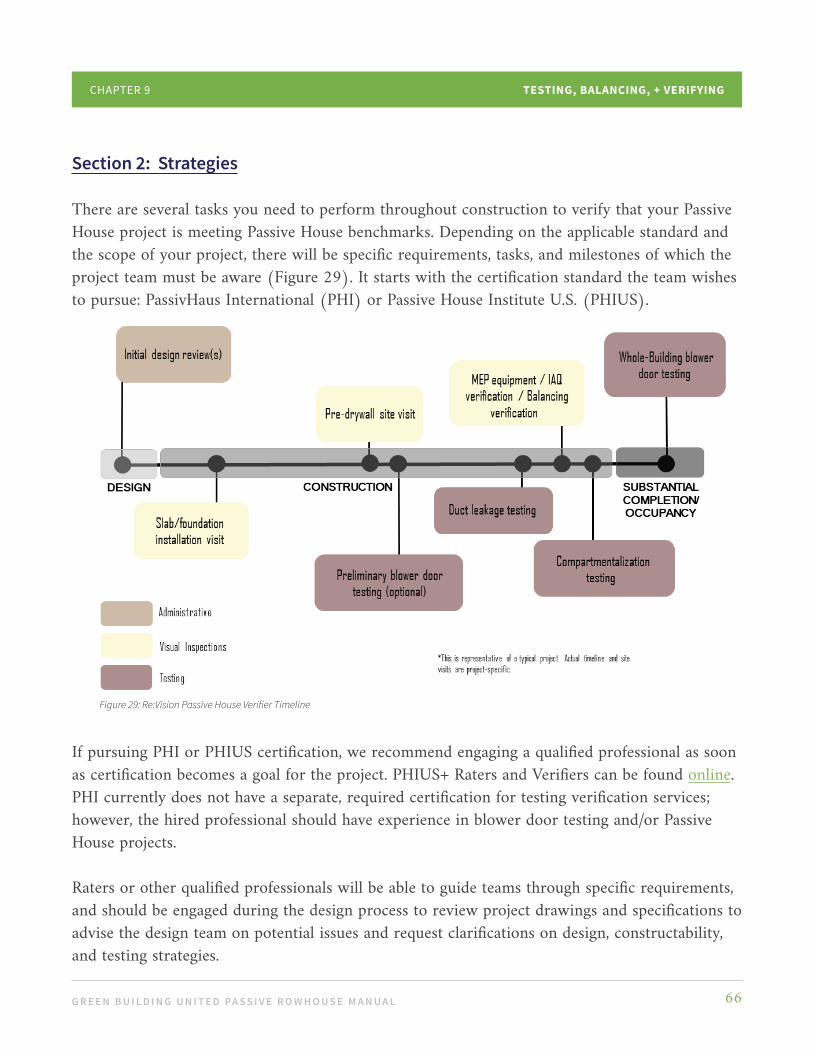
G R E E N B U I L D I N G U N I T E D PA S S I V E R O W H O U S E M A N U A L 66
TESTING, BALANCING, + VERIFYINGCHAPTER 9
Section 2: Strategies
There are several tasks you need to perform throughout construction to verify that your Passive House project is meeting Passive House benchmarks. Depending on the applicable standard and the scope of your project, there will be specific requirements, tasks, and milestones of which the project team must be aware (Figure 29). It starts with the certification standard the team wishes to pursue: PassivHaus International (PHI) or Passive House Institute U.S. (PHIUS).
If pursuing PHI or PHIUS certification, we recommend engaging a qualified professional as soon as certification becomes a goal for the project. PHIUS+ Raters and Verifiers can be found online. PHI currently does not have a separate, required certification for testing verification services; however, the hired professional should have experience in blower door testing and/or Passive House projects.
Raters or other qualified professionals will be able to guide teams through specific requirements, and should be engaged during the design process to review project drawings and specifications to advise the design team on potential issues and request clarifications on design, constructability, and testing strategies.
Figure 29: Re:Vision Passive House Verifier Timeline

G R E E N B U I L D I N G U N I T E D PA S S I V E R O W H O U S E M A N U A L 67
TESTING, BALANCING, + VERIFYINGCHAPTER 9
Examples of design review items a Rater may verify include location of balancing dampers, air sealing details at difficult areas, and pressure balancing strategies. It is also helpful to develop a blower door test plan to identify who is responsible for what when preparing for the rough or final blower door tests. Check out this video to see what a blower door test looks like firsthand.
Depending on the scope of the project, the following site visits, tasks, and tests may be required as part of the Rater’s services:
STE P 1
Pre-slab Site Visit
This site visit may not be applicable for retrofit rowhouse projects. However, if there is any foundation or slab work being completed, the Rater will verify insulation installation as well as general compliance with other standard prerequisites as necessary.
STE P 2
Pre-insulation Air Infiltration Testing
A pre-insulation, pre-drywall blower door test helps identify areas of leakage through the project’s air barrier. This may be one of the last opportunities to seal the building before this installation is covered, which is why having the contractor on-site ready to address leakages while the blower door is in operation is encouraged. If the project is meeting air infiltration rates at this point, it is generally a good indicator that the project will be well positioned to pass the final blower door test.
STEP 3
Pre-drywall Site Visit
At this site visit, insulation installation will be observed for quality and duct leakage testing may also be completed if ready, as shown in Figure 30.
Liquid Sealer
Batt Insulation
Air Membrane
Figure 30: Pre-drywall Site Visit Example

G R E E N B U I L D I N G U N I T E D PA S S I V E R O W H O U S E M A N U A L 68
TESTING, BALANCING, + VERIFYINGCHAPTER 9
STE P 4
Duct Leakage Testing
If a project has ducted HVAC systems, duct leakage testing may be required. The purpose of ductwork is to transport a specific amount and/or temperature of air to specific spaces. If a project’s ductwork is not installed or sealed properly, airflow may be lost to areas not meant to receive airflow (e.g., above-ceiling plenums). Not only does this cause HVAC systems to use more energy, but ductwork losses can lead to comfort and operational issues.
STE P 5
Air Balancing Verification
An HVAC plan will have designed airflows to specific areas. Similar to duct leakage testing, air balancing verification helps ensure that the designed airflow is getting to where it needs to go. While issues with heating and cooling airflows may cause comfort issues, issues with ventilation airflows may cause larger health and durability problems.
STEP 6
Installation Checks
A Rater will verify that installed equipment, such as dishwashers, refrigerators, HVAC systems, DHW systems, and lighting are correctly designed and meet required standards, such as Energy Star.
STEP 7
Whole-building Air Infiltration Testing
This is also known as the final blower door test. The project must undergo this testing to verify required air infiltration targets are met.
STEP 8
Infrared Scans
An infrared camera may be used to identify areas of thermal bridging in the project. Issues may include areas of missing insulation or sealant, unsealed penetrations, and thermal bridging.
G R E E N B U I L D I N G U N I T E D PA S S I V E R O W H O U S E M A N U A L 69
TESTING, BALANCING, + VERIFYINGCHAPTER 9
During construction, the Rater should make periodic site visits to inspect construction progress, and share any noted deficiencies with the project team. The Rater will review insulation, air sealing, and systems installation quality, and should work closely with the project’s contractor and design team to address any issues that arise in order to prepare the project to pass all in-field checks and testing.
Once construction begins, outline preliminary testing in the project schedule. Testing requirements will vary depending on the project scope; however, whole building air infiltration testing will always be required.
While not required, we strongly recommend a preliminary blower door test - to be completed once the building is enclosed but the drywall has not been installed. When the preliminary blower door testing is performed, leak chasing
should be completed, often using a smoke tracer. This task also provides a learning opportunity for contractors and other team members to see where problem areas are and help correct them. It may be beneficial to isolate a window and test that assembly with a duct leakage fan device before all windows are installed, ensuring that the window system as designed and installed, is airtight. Additionally, infrared (IR) scans can be a helpful diagnostic to identify areas of thermal bridging during construction. Pre-drywall IR scans can help catch areas that may need insulation repair or additional sealing before assemblies are covered up.
Raters will identify deficiencies to be corrected by the construction team and coordinate their resolution. If the project is not passing required tests, rework or retesting may be required to meet the performance criteria.
Section 3: Conclusion
Ideally, a Rater should be involved in the design phase of the project, even if their scope does not require design phase activities. A Rater can help advise and highlight items in the drawings or specs that may require clarifications or revisions in order to pass in-field testing and inspections. They may also have lessons learned from other projects that could help inform best practices with respect to construction to project administration.
Understand requirements of your selected Passive House standard. Engage a Rater early on to verify that the project design accounts for any specific PHI or PHIUS requirements and/or
G R E E N B U I L D I N G U N I T E D PA S S I V E R O W H O U S E M A N U A L 70
TESTING, BALANCING, + VERIFYINGCHAPTER 9
prerequisites that may be applicable to the project. Teams do not want to discover that design issues were overlooked or unclear. Be aware of the different air infiltration metrics between PHI and PHIUS. PHI uses a maximum air infiltration rate of 0.6 ACH50 while PHIUS establishes a maximum leakage rate based on square footage of the enclosure area.
To help streamline contractor coordination and uncertainty, it is helpful to have mock-ups or examples of good installation details available on-site for review and reference. At a minimum, a verification kickoff meeting should be performed with the design team, contractor, and applicable sub-contractors at the start of construction. This is also a good opportunity to do a pre-mortem, in which the Rater reviews things that could potentially lead to failure on the project. Ask questions and be humble; this is necessary and challenging work but can also be fun!
The Rater is also responsible for compiling and submitting all required documentation to PHIUS or PHI upon project completion. Upon review, the certifying body may have some comments for clarification, which the Rater and team will address.
If there are no comments regarding the submission and the project is meeting all necessary requirements, the project achieves certification.
It is now time to celebrate the diligent work of the project team and welcome the owner into their newly certified Passive Rowhouse!

G R E E N B U I L D I N G U N I T E D PA S S I V E R O W H O U S E M A N U A L 71
Conclusion
Congratulations - you made it to the end! At this point you have read through the Manual and maybe even started the design and construction phases of your project. With your strong team, Passive House Consultant, and project goals set, you are well positioned to use this Manual to achieve a Passive Rowhouse. We are excited to have shared our knowledge and experience to help guide you through this process.
Because Passive House is rooted in building science, the standard is continuously adapting to new information and technologies. We encourage you to stay up-to-date on standard changes and best practices for high performance. One of the best ways to stay informed is by joining our Passive House Community - which you can learn all about on Green Building United’s website!
Together we can continue to grow and share our experience, working to make Passive House design and construction mainstream for a decarbonized, equitable built environment in all our neighborhoods and communities.

G R E E N B U I L D I N G U N I T E D PA S S I V E R O W H O U S E M A N U A L 72
Appendix
Building Address
Street Address
City, State, Zip Code
Date of Evaluation
Age of Building (years) Tip: If your project is relatively new construction, a major renovation may not be be financially practical, but we recommend renovating to Passive House if you can. Older buildings may not have been renovated for 40-50 years and it is probably time to make this classic rowhouse a Passive Rowhouse!
General (G)
G.1 Climate Zone Tip: The Passive House energy model is climate specific based on the project location. Climate zones are defined in ANSI/ASHRAE Standard 169-2013, which sets out design temperatures and other information required for the energy model. Building code also defines climate zone and climate requirements. Philadelphia and environs are located in Climate Zone 4A, Hot and Humid. This is different than the USDA Plant Hardiness zone.
G.2 Cost of Acquisition (I.e., the cost to purchase the property) Tip: Include this when looking at the overall project cost and budget.
G.3 Project Budget Tip: This is a realistic assessment of the available funds to complete the project. The Project Cost is the sum of all costs to complete the project from beginning to end, and includes design professional fees (architect, structural, MEP, Passive House Consultant, etc.), certification, permits, testing and approvals, as well as construction costs. You may decide to phase the project if your Project Budget is less than the Project Cost.
SITE OPPORTUNITY AND CONSTRAINT WORKSHEET
Following is a list of items, information, and tips to consider when evaluating a property for Passive House, low energy, and/or low carbon renovation. This information is part of the Owner’s Project Requirements and should be shared with the design and construction team. Note that each of these items affects the project cost and schedule.
G R E E N B U I L D I N G U N I T E D PA S S I V E R O W H O U S E M A N U A L 73
APPENDIX
G.4 PH Certification Tip: Decide whether you are pursuing Passive House certification, or only applying Passive House principles. Certification adds to project costs but assures that design performance is achieved in the final project.
G.5 Gut Rehab Tip: Gut rehab projects remove all building finishes and systems down to the underlying structure and provides the most opportunities to resolve building science issues and achieve highest performance.
G.6 Partial Renovation Tip: Partial renovations selectively define areas of a building that will not be touched during construction. They limit the access to basic building structure and may make construction and subsequent energy performance more difficult.
G.7 Program Requirements Tip: Passive House performance is possible for all building types; however, a particular project may have mandatory program or use requirements that add cost or design and construction difficulties. For example, including a sauna results in increased energy and moisture vapor issues.
G.8 Problems Solved by New Addition Tip: A project may include an addition along with renovations to the base building. The addition may provide an opportunity to add to the overall building performance as well as improve the utility or aesthetics of the building. It may rebuild a poorly performing wall, add windows that provide “free” energy in wintertime, or provide space for updated mechanicals.
G.9 Hazardous Materials Tip: Older buildings were constructed with well-intended building materials like lead paint (stable, water- resistant, durable, and color-fast) and asbestos (inexpensive, fire-proof, durable, and easily workable). We now know that these materials have serious health impacts on humans and other living beings. These materials must be safely encapsulated or lawfully removed as part of the project.
Site Constraints (S)
S.1 Zoning Constraints and Property Line Location Tip: Municipal zoning requirements define the use and dimensions/sizes of buildings that may be constructed in a particular location. Understand the limitations (and opportunities) of your property. Zoning requirements may determine whether an addition may be added as-of-right. If the existing rowhouse is built up to the property line, adding insulation to the face of the building may not be permitted, affecting the insulation and air sealing strategy.
SITE OPPORTUNITY AND CONSTRAINT WORKSHEET CONT’D

G R E E N B U I L D I N G U N I T E D PA S S I V E R O W H O U S E M A N U A L 74
APPENDIX
SITE OPPORTUNITY AND CONSTRAINT WORKSHEET CONT’D
S.2 Building Code Restrictions Tip: Building code is concerned with life, safety, and health, and includes requirements for specifications such as ventilation, room size, and access. Passive House design solutions may conflict with building or other codes.
S.3 Adjacent Buildings, Vegetation, and Obstructions Tip: By definition, rowhouses are attached to adjacent properties and often fixed in orientation, without much (if any) control over adjacent properties or conditions.
S.4 Orientation for Passive Solar Access Tip: Passive solar access refers to the availability of free energy from the sun through windows or skylights. South facing works best, and we recommend working with a solar consultant to define the best strategy.
S.5 Orientation for Solar Access for Energy Generation Tip: Net zero performance relies on the use of renewable energy in addition to low energy Passive House building techniques. Circumstances may preclude a renewable energy strategy for your project, but as stated in S.4, we recommend working with a solar consultant to review all options.
S.6 Future Solar Access Restrictions Tip: Zoning regulations may allow for nearby structures that shade or affect your access to sunlight in the future. Plan accordingly and do not rely on a condition that may change.
S.7 Storm Water Management, Drainage, Flooding Tip: Storm water management (I.e., controlling the flow of rain and groundwater) is the responsibility of each project, and a building permit requirement. Water control is a primary concern of any building, affecting durability, comfort, and health.
S.8 Soil Type, Wetlands, Brownfield, Sink Holes, Radon Tip: Conditions below the ground affect conditions above the ground. Your project must be structurally sound with controlled water and appropriate ventilation. Remediation of unsatisfactory conditions is a project requirement that adds to project cost.
Building History (H)
H.1 Historic Designation Tip: Buildings may be designated as historically significant by the municipality, which may affect the kinds of exterior work that can be performed, as well as the length of approval processes. Historical facades generally need to be kept as-is with little opportunity for adding exterior insulation or other applied improvements. In general, historical designation adds to the value of the building and the community.

G R E E N B U I L D I N G U N I T E D PA S S I V E R O W H O U S E M A N U A L 75
SITE OPPORTUNITY AND CONSTRAINT WORKSHEET CONT’D
H.2 Cultural Significance to be Preserved Tip: A culturally significant structure has value to the community in which it is located and may place restrictions on the extent of the project. This is an intangible project requirement that needs to be factored in the project cost and schedule.
H.3 Architectural Features to be Preserved Tip: Architectural features - such as intricate cornices, brick, or stonework, or highly crafted construction - contribute to the beauty and value of the building and is generally irreplaceable if removed or damaged. They may also limit possible Passive House design solutions.
H.4 Recent Renovations or Additions that Preclude Optimal Solutions Tip: Renovations or additions may reflect a significant investment that should be left in place; however, if the addition is not Passive House worthy, the overall building performance may be affected. This may be a program requirement that needs to be accommodated in the building design.
H.5 Recent Renovations or MEP Replacements Tip: This is a common occurrence that may affect building performance. A broken hot water heater is an emergency that needs to be resolved immediately – and is often replaced with any available unit, which may negatively impact energy efficiency. Similarly, a recent roof replacement may preclude adding roof insulation in the optimal location, such as above the roof sheathing.
Building Envelope (E)
E.1 Aesthetics Tip: Owners want to keep buildings looking good, so changing them may limit the extent of renovations, which may in turn affect building performance. “Ugly ducklings” with good bones are preferred prospects for Passive House renovation.
E.2 Simple Form Tip: Simple, rectangular forms generally achieve Passive House performance more easily than other forms due to the decreased possibility of difficult conditions and thermal bridges, and have an optimal surface:volume ratio.
E.3 Complex Form Tip: Complex forms with lots of “ins and outs” can be more difficult to solve from a building science standpoint, adding complexity and possible cost; however, any form can achieve Passive House certification.
E.5 Construction Type Tip: Traditionally, Philadelphia rowhouses have masonry (brick or stone) bearing walls, with wood floor and roof structure. Rear additions may be wood or stone structure. New construction tends to be wood construction. These assemblies have different strategies for insulating and air sealing.
APPENDIX
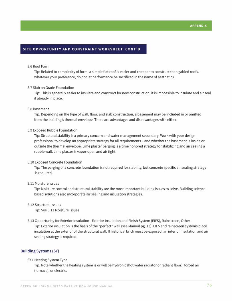
G R E E N B U I L D I N G U N I T E D PA S S I V E R O W H O U S E M A N U A L 76
APPENDIX
SITE OPPORTUNITY AND CONSTRAINT WORKSHEET CONT’D
E.6 Roof Form Tip: Related to complexity of form, a simple flat roof is easier and cheaper to construct than gabled roofs. Whatever your preference, do not let performance be sacrificed in the name of aesthetics.
E.7 Slab on Grade Foundation Tip: This is generally easier to insulate and construct for new construction; it is impossible to insulate and air seal if already in place.
E.8 Basement Tip: Depending on the type of wall, floor, and slab construction, a basement may be included in or omitted from the building’s thermal envelope. There are advantages and disadvantages with either.
E.9 Exposed Rubble Foundation Tip: Structural stability is a primary concern and water management secondary. Work with your design professional to develop an appropriate strategy for all requirements – and whether the basement is inside or outside the thermal envelope. Lime plaster parging is a time honored strategy for stabilizing and air sealing a rubble wall. Lime plaster is vapor-open and air tight.
E.10 Exposed Concrete Foundation Tip: The parging of a concrete foundation is not required for stability, but concrete specific air sealing strategy is required.
E.11 Moisture Issues Tip: Moisture control and structural stability are the most important building issues to solve. Building science- based solutions also incorporate air sealing and insulation strategies.
E.12 Structural Issues Tip: See E.11 Moisture Issues
E.13 Opportunity for Exterior Insulation - Exterior Insulation and Finish System (EIFS), Rainscreen, Other Tip: Exterior insulation is the basis of the “perfect” wall (see Manual pg. 13). EIFS and rainscreen systems place insulation at the exterior of the structural wall. If historical brick must be exposed, an interior insulation and air sealing strategy is required.
Building Systems (SY)
SY.1 Heating System Type Tip: Note whether the heating system is or will be hydronic (hot water radiator or radiant floor), forced air (furnace), or electric.

G R E E N B U I L D I N G U N I T E D PA S S I V E R O W H O U S E M A N U A L 77
APPENDIX
SITE OPPORTUNITY AND CONSTRAINT WORKSHEET CONT’D
SY.2 Heating Fuel Tip: While Passive House performance does not depend on the heating fuels that are used (electric, fuel oil, natural gas), preference is for electrification in order to eliminate all fossil fuel sources. Efficient HVAC systems used for Passive House projects are typically electric.
SY.3 Heating System Life Span Tip: Replacing an existing heating system that is 10-15 years old is an easy decision to make. It is at the end of the useful life and will need to be replaced shortly. Choosing to replace a 3- to 5-year-old system will have to balance cost with the affect on HVAC system design and performance. SY.4 Air Conditioning System Tip: Air conditioning is required in hot humid climates like Philadelphia for comfort and health. This is important to consider as climate change is increasing overall temperature and frequency of high heat days.
SY.5 Air Conditioning System Life Span Tip: Similarly to Heating System replacements; replacing a new air conditioning system, no matter how inefficient it is, will factor into your financial considerations.
SY.6 Hot Water System Tip: Hot water is generated by heating water with electricity, natural gas, or fuel oil. The hot water heater may be part of the boiler system, or an electric (recommended) or gas on-demand system.
SY.7 Hot Water Fuel Tip: See SY. 2 Heating Fuel
SY.8 Hot Water Heater Life Span Tip: See SY.3 Heating System Life Span and SY.5 Air Conditioning System Life Span
SY.9 Plumbing System Materials Tip: Older homes may have copper piping. Recent building code updates allow the use of PEX manifold systems in lieu of copper pipes.
SY.10 Plumbing System Life Span Tip: See SY.3 Heating System Life Span and SY.5 Air Conditioning System Life Span
SY.11 Plumbing Access Tip: Note whether the existing piping is easily accessible or hidden in walls and will remain. If pipes are not insulated, they need to be. If in poor condition, plumbing will need to be replaced regardless of accessibility.
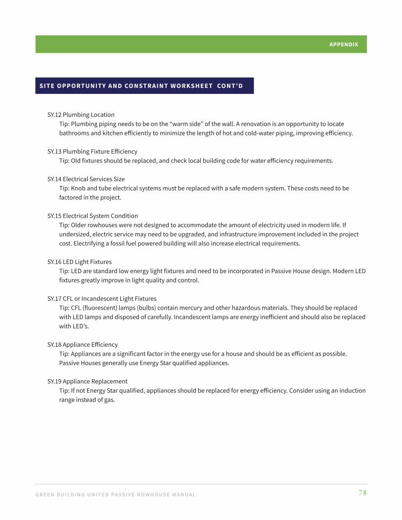
G R E E N B U I L D I N G U N I T E D PA S S I V E R O W H O U S E M A N U A L 78
APPENDIX
SITE OPPORTUNITY AND CONSTRAINT WORKSHEET CONT’D
SY.12 Plumbing Location Tip: Plumbing piping needs to be on the “warm side” of the wall. A renovation is an opportunity to locate bathrooms and kitchen efficiently to minimize the length of hot and cold-water piping, improving efficiency.
SY.13 Plumbing Fixture Efficiency Tip: Old fixtures should be replaced, and check local building code for water efficiency requirements.
SY.14 Electrical Services Size Tip: Knob and tube electrical systems must be replaced with a safe modern system. These costs need to be factored in the project.
SY.15 Electrical System Condition Tip: Older rowhouses were not designed to accommodate the amount of electricity used in modern life. If undersized, electric service may need to be upgraded, and infrastructure improvement included in the project cost. Electrifying a fossil fuel powered building will also increase electrical requirements.
SY.16 LED Light Fixtures Tip: LED are standard low energy light fixtures and need to be incorporated in Passive House design. Modern LED fixtures greatly improve in light quality and control.
SY.17 CFL or Incandescent Light Fixtures Tip: CFL (fluorescent) lamps (bulbs) contain mercury and other hazardous materials. They should be replaced with LED lamps and disposed of carefully. Incandescent lamps are energy inefficient and should also be replaced with LED’s.
SY.18 Appliance Efficiency Tip: Appliances are a significant factor in the energy use for a house and should be as efficient as possible. Passive Houses generally use Energy Star qualified appliances.
SY.19 Appliance Replacement Tip: If not Energy Star qualified, appliances should be replaced for energy efficiency. Consider using an induction range instead of gas.

G R E E N B U I L D I N G U N I T E D PA S S I V E R O W H O U S E M A N U A L 79
Glossary
Adiabatic | A balanced system where there is little to no heat loss or gain through a wall, but allows air and water vapor to move through the wall.
Air Barrier Red Line (ABRL) | A continuously drawn red pencil line (signifying air barrier) around the enclosure details; A critical continuity test of the design that, is focused on maintaining continuity and proper location of the water, air, vapor, and thermal control layers: identifies where the air barrier will be placed in the wall assembly, points to possible thermal bridges, highlights critical junction points, and signals where to focus particular effort to ensure airtight construction.
Air Boss | A dedicated, on-site team member who is responsible for quality control, ongoing training, and communication between the owner, construction trades, and design teams to ensure consistent, airtight construction.
Bird Safe Treatments | A window or other structural element designed to make birds aware of the structure, thereby reducing possible collisions and bird fatality.
Buck | A wood frame that is set into the wall to define an opening for a window or door.
Climate Change | Changes in global or regional climate patterns that are attributed to increased levels of atmospheric carbon dioxide and other greenhouse gases emitted largely by human systems such as buildings and transportation.
Cooling Dry Bulb (DB) and Wet Bulb (WB) | DB and WB temperatures are used together to design air conditioning systems. DB is the ambient temperature measured by a regular thermometer. WB is measured with a wetted thermometer and measures the lowest achievable temperature through natural evaporation.
Decarbonization | The reduction of carbon dioxide emissions through the use of low carbon power sources, such as electricity generated from renewable sources, to reduce greenhouse gasses that result in climate change.
Dewpoint | The temperature to which air must be cooled to become saturated with water vapor. When cooled further, the airborne water vapor will condense to form liquid water (dew). When air cools to its dew point through contact with a surface that is colder than the air, water will condense on the surface, which can lead to mold and mildew growth.
Divided Lite | Windows and doors with multiple small panes of glass that are separated by muntins or grilles. True divided lite windows and doors are assemblies of individual small windows; currently, most divided lite windows are made with a single lite with simulated muntins or grilles that can be mechanically attached, embedded between the panes, or affixed to the window with glue.

G R E E N B U I L D I N G U N I T E D PA S S I V E R O W H O U S E M A N U A L 80
GLOSSARY
Domestic Hot Water (DHW) | A key player in Passive House performance. Water heaters use a significant amount of a home’s energy to heat and then maintain sufficient temperatures. Optimizing whole house energy demand by comparing and evaluating the efficiencies of various DHW systems is recommended.
Effective R-value | Calculation that takes into account the cumulative value of thermal resistance for all materials within the assembly.
Egress | A place or means of going out. In the context of a rowhouse, egress points are doors and some windows.
Embodied Carbon | Measured from cradle to grave, it is the total calculated carbon of a product or building, including its extraction, production, transportation, and end-of-life use. Embodied Carbon can represent 20-50% of the total whole life carbon emissions of new buildings and, unlike carbon from operations, cannot be reduced after installation.
Energy Recovery Ventilation (ERV) | Part of the Passive House HVAC system in residential and commercial buildings, the ERV exchanges the energy contained in exhaust air with the incoming ventilation air to treat or pre-condition air with minimum temperature loss to the conditioned air.
Energy Star | A program run by the U.S. Environmental Protection Agency (EPA) and U.S. Department of Energy (DOE) that promotes energy efficiency. To optimize energy consumption in a Passive House, all appliances should be Energy Star certified.
Energy Use Intensity (EUI) | Calculated by dividing a building’s total energy consumed in one year by its total gross floor area. The energy-per-square-foot (or square-meter) per year is an indicator of the energy efficiency of a building’s design and/or operations and allows the building operators to easily benchmark against similar buildings.
Fenestration | Any opening in a building’s membrane, mainly as windows and doors.
Heating Drybulb (DB) | Equivalent to dry bulb temperature; the temperature indicated on a thermometer reading.
Hygrothermal and Analysis/Modeling | The movement of heat and moisture through building assemblies (walls). Repeated wetting, drying, freezing, and thawing of wall systems can cause problems such as condensation, mold growth, rot, loss of thermal performance, and possibly premature system failure. During the design phase, the proposed wall systems can be computer modeled to run simulations of the movement of heat and moisture to identify the best wall assembly for the project that optimizes performance and minimizes risk. If warranted, post construction physical testing can be used to test performance and/or identify problems. WUFI is a common program that predicts hygrothermal performance.
Infrared (IR) Scanner | A non-invasive performance testing device that detects infrared energy (heat) and converts it into a thermal image or video that enables visual monitoring of thermal performance, and follows the user to identify and evaluate the relative severity of heat-related problems.

G R E E N B U I L D I N G U N I T E D PA S S I V E R O W H O U S E M A N U A L 81
GLOSSARY
Keying | How keys are matched for door locks. When purchasing doors from European sources, be aware that the lock mechanisms often contain welded cores or keyways. Keys are unique to the door, meaning locks cannot easily be changed. When ordering, specify how the door locks should be configured to avoid this potential complication.
Latent Loads | In air conditioning, latent energy refers to the relative humidity or moisture in the air; a high latent load means that the relative humidity is high. ‘Sensible capacity’ is that required to lower the temperature and ’latent capacity’ is that required to remove the moisture from the air; it is measured as the wet bulb.
Lift and Slide | A sliding window or door that uses special hardware to allow the panels to lift off the track and weather-stripping, and glide open or closed. When closed, the handle lowers the panels on the track creating a tight fit and limiting the air infiltration exhibited by traditional sliding windows and doors.
Manual J | A heating and cooling load calculation that determines HVAC design and sizing to maintain occupant comfort.
Parging | The process of coating/resurfacing the visible aboveground portion of the masonry or stone walls of a structure.
Passive House Rater | Experienced professionals providing third party, on-site quality assurance and verification for projects pursuing Passive House certification.
Perm/Perm Rating | Permiability; The rate at which air, gasses, and vapor pass through a membrane. The higher the number, the more readily gaseous water vapor can diffuse through the material:
• < 0.1 is considered a Class I impermeable vapor retarder (i.e., vapor barrier)• > 0.1 and </= 1 is considered a Class II semi-permeable vapor retarder• > 1 and < 10 is a Class III permeable vapor retarder;• > 10 is highly permeable and not considered to be a vapor retarder.
Pre-mortem | A collaborative project team visioning exercise that is conducted before a project starts, which is essential in a Passive House project to protect the integrity of the air barrier. Goals are to imagine possible failure points/steps in the project and create a plan to prevent them for increases chance of project success.
R-value | A measure of thermal resistance of a single, homogeneous building material.
Sensible Heat Ratio (SHR) | The sensible heat or cooling load divided by the total heat or cooling load. E.g., if the SHR for an evaporator is 75% (0.75), 75% of the load cools the air (sensible load) and 25% of the load dehumidifies the air (latent load).
Sensible Load | Refers to the dry bulb temperature of the building.
Solar Heat Gain Coefficient (SHGC) | Expressed as a number between 0 and 1, is the fraction of incident solar
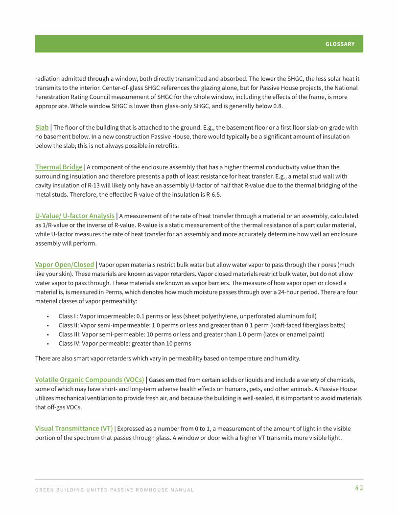
G R E E N B U I L D I N G U N I T E D PA S S I V E R O W H O U S E M A N U A L 82
GLOSSARY
radiation admitted through a window, both directly transmitted and absorbed. The lower the SHGC, the less solar heat it transmits to the interior. Center-of-glass SHGC references the glazing alone, but for Passive House projects, the National Fenestration Rating Council measurement of SHGC for the whole window, including the effects of the frame, is more appropriate. Whole window SHGC is lower than glass-only SHGC, and is generally below 0.8.
Slab | The floor of the building that is attached to the ground. E.g., the basement floor or a first floor slab-on-grade with no basement below. In a new construction Passive House, there would typically be a significant amount of insulation below the slab; this is not always possible in retrofits.
Thermal Bridge | A component of the enclosure assembly that has a higher thermal conductivity value than the surrounding insulation and therefore presents a path of least resistance for heat transfer. E.g., a metal stud wall with cavity insulation of R-13 will likely only have an assembly U-factor of half that R-value due to the thermal bridging of the metal studs. Therefore, the effective R-value of the insulation is R-6.5.
U-Value/ U-factor Analysis | A measurement of the rate of heat transfer through a material or an assembly, calculated as 1/R-value or the inverse of R-value. R-value is a static measurement of the thermal resistance of a particular material, while U-factor measures the rate of heat transfer for an assembly and more accurately determine how well an enclosure assembly will perform.
Vapor Open/Closed | Vapor open materials restrict bulk water but allow water vapor to pass through their pores (much like your skin). These materials are known as vapor retarders. Vapor closed materials restrict bulk water, but do not allow water vapor to pass through. These materials are known as vapor barriers. The measure of how vapor open or closed a material is, is measured in Perms, which denotes how much moisture passes through over a 24-hour period. There are four material classes of vapor permeability:
• Class I : Vapor impermeable: 0.1 perms or less (sheet polyethylene, unperforated aluminum foil)• Class II: Vapor semi-impermeable: 1.0 perms or less and greater than 0.1 perm (kraft-faced fiberglass batts)• Class III: Vapor semi-permeable: 10 perms or less and greater than 1.0 perm (latex or enamel paint) • Class IV: Vapor permeable: greater than 10 perms
There are also smart vapor retarders which vary in permeability based on temperature and humidity.
Volatile Organic Compounds (VOCs) | Gases emitted from certain solids or liquids and include a variety of chemicals, some of which may have short- and long-term adverse health effects on humans, pets, and other animals. A Passive House utilizes mechanical ventilation to provide fresh air, and because the building is well-sealed, it is important to avoid materials that off-gas VOCs.
Visual Transmittance (VT) | Expressed as a number from 0 to 1, a measurement of the amount of light in the visible portion of the spectrum that passes through glass. A window or door with a higher VT transmits more visible light.

We are happy to be able to voluntarily provide this information for your consideration in your project. Green Building United and its Communities make efforts to update this material as often as needed. Nevertheless, it might be possible that contents are incomplete, incorrect, or not appropriate for your project.
These materials are offered with no guarantee or liability for their accuracy. Each project depends on the individual facts and lies within the competence of the professionals involved in that project.
Green Building United and its Communities do not take responsibility and are not liable for losses or damages related to your project.
Image Credit: Alex Bruce