Embed Size (px)
Citation preview
PASSIVE ICING SHIELDS FOR RAILROAD TUNNEL IN GALLITZIN, PA
Authors’ Names and Contact Information:
Phaidra Campbell Jacobs Associates 1109 First Ave, Suite 501 Seattle WA 98101 206.588.8112 Ruth Brown Norfolk Southern Railway 1200 Peachtree St NE Atlanta GA 30309 404.529.1225 Joseph Schrank, PE, PEng Jacobs Associates 1109 First Ave, Suite 501 Seattle WA 98101 206.588.8125
© 2012 AREMA

Word Count This manuscript has 3,374 words, 10 figures and 1 table.
© 2012 AREMA
ABSTRACT
Severe seepage and resultant winter icing restricted clearances in the Allegheny Tunnel
lining and covered the track structure for hundreds of feet, interfering with traffic and requiring
significant maintenance. The tunnel was enlarged to a double track/double stack structure in the
mid-1990s by CONRAIL, predecessor to Norfolk Southern Railway (NSR) in central
Pennsylvania. At that time, passive icing shields (no heat added) were installed for about 335
linear feet (102 m) as part of the enlargement project. These shields consisted of interlocking
panels fabricated from a layer of closed-cell polyethylene sandwiched between galvanized steel
sheets. The back of the panels was covered with a sprayed waterproof sealant; however, the
underside was not. After 15 years of use, many of the panels were seriously deteriorated, mostly
due to locomotive exhaust blast to the underside and rusting of the rock bolt hangers that
connected the panels to the adjacent rock.
In 2010, NSR requested Jacobs Associates design a retrofit or replacement for the
existing icing shields that would fit in the clearance envelope and could be implemented in work
windows of 2 to 6 hours duration. Jacobs Associates, working with NSR’s Engineering
Department, designed a self-supporting structure consisting of steel sets lagged between the
webs with closed-cell polyethylene insulation, a thick drainage mat over the back of the structure
for seepage control, and shotcrete covering the underside to protect the structure from
locomotive blast. Additionally, individual small seeps in other areas of the tunnel were captured
using bladders encased in shotcrete.
© 2012 AREMA

INTRODUCTION
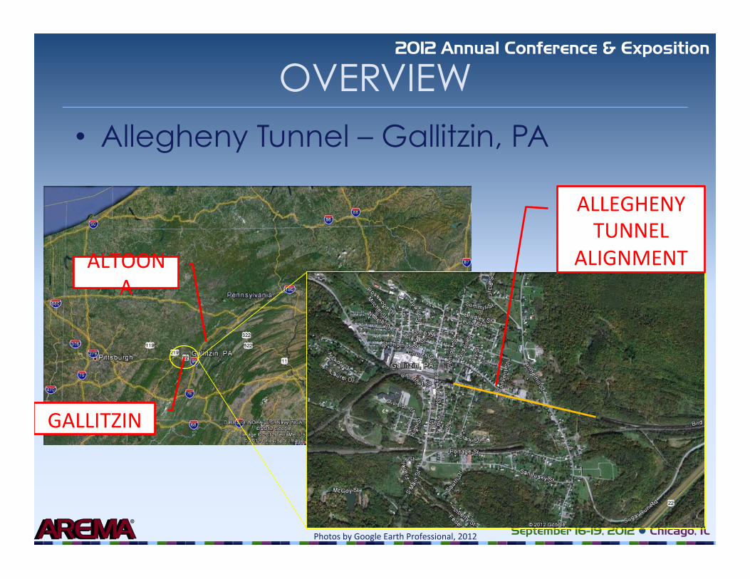
Allegheny Tunnel is located at the summit of the Allegheny Mountains in Gallitzin,
Pennsylvania, and crosses Cambria and Blair counties (Figure 1). Allegheny Tunnel is one of
three Gallitzin tunnels that were constructed to allow train passage running east to west through
the mountain range. The tunnel was constructed between 1851 and 1854 by the Pennsylvania
Railroad Corporation using steam shovels and drill-and-blast operations to a length of 3,600
linear feet (1,097 m) (Station 0+00 to 36+00) at an elevation of 2,167 feet (661 m). The lining
consisted of a brick arch and masonry sidewalls, with ashlar sandstone masonry at the east and
west portals.
Ownership of Allegheny Tunnel was transferred to Consolidated Rail Corporation
(CONRAIL) in 1976. From 1994 to 1996, excavation was completed to expand the tunnel from a
single track/single stack to a double track/double stack structure. The approximate cost for this
construction was $27.7 million. Work included removal of approximately 90,000 cubic yards of
original masonry and brick lining, and approximately 12 feet of lining and rock per foot of tunnel
for the second track. The entire tunnel was relined with a combination of shotcrete and rock bolts
for most of its length, while the east end had 550 feet of steel sets installed, and the west portal
was cast-in-place concrete (Figure 2). The original ashlar masonry portal headwalls and portal
facade were reconstructed with salvaged masonry blocks in order to replicate the original historic
composition of the structure (1). In addition, premanufactured icing shields were installed at
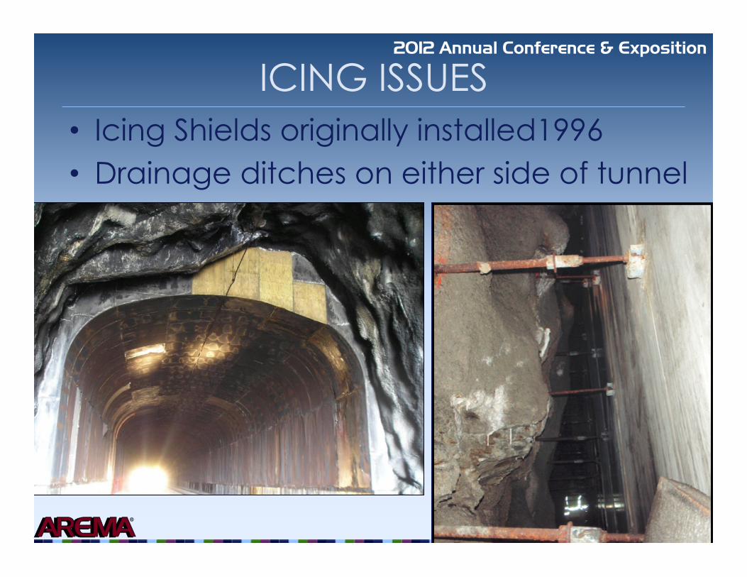
several sections of the tunnel that were experiencing significant seepage and freezing. To control
drainage, through-tunnel drain lines were installed at the north and south inverts along with two
steel pipes to carry water transiting from one portal to the other and to catch in-tunnel seepage.
Ownership of the Allegheny Tunnel was transferred to Norfolk Southern Railway (NSR) in
© 2012 AREMA
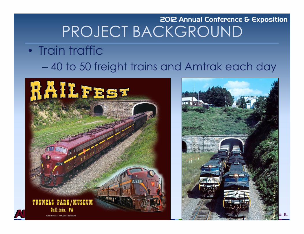
1999. Currently, 40 to 50 freight trains and Amtrak passenger service operate through this tunnel
each day at a speed of 50 mph.
ICING ISSUES
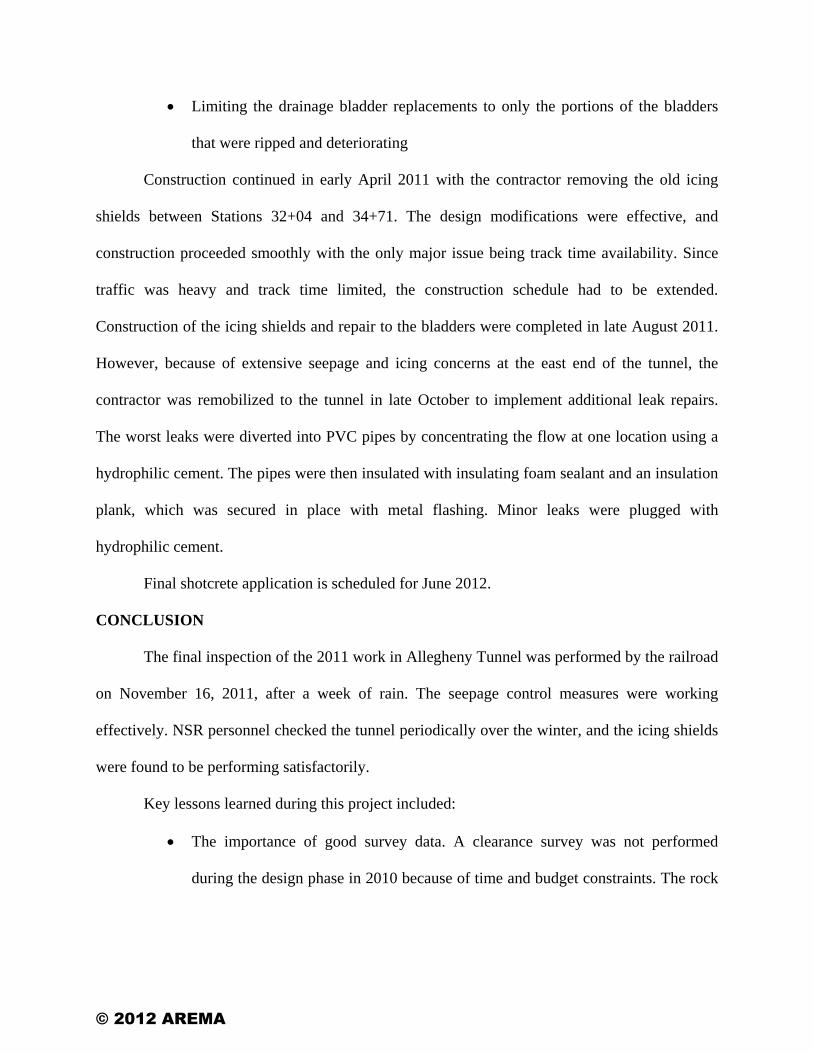
The 1996 icing shields were designed to be a passive system that would control ice
formation in the tunnel (Figure 3). The icing shields were manufactured off site and consisted of
3-inch-thick (75 mm) panels constructed of two thin galvanized steel sheets with a core of
polyurethane insulation planks between them. The steel sheets acted as protection to the
polyurethane insulation planks while also providing structural rigidity to the system. Individual
steel sheets were connected to adjacent steel sheets with camlock devices. The entire shield
structure was suspended from the irregular shotcrete perimeter liner with hangers attached to the
shield panels with screws, and was founded on formed concrete footings. The ends of the icing
shield were bulkheaded with marine grade plywood that trapped air between the icing panels and
the shotcrete tunnel liner surface. All of the attachment hardware was either stainless steel or
otherwise protected from the corrosive effects of the seepage. In addition, a layer of heavy
mastic protection was later painted on the field side of the sheets to protect against corrosion.
The steel shields were not meant to offer structural support to the tunnel ground or ice
loads, but rather to inhibit the formation of ice by maintaining the temperature of the seepage
above freezing until the seepage entered the tunnel drainage system. This system seemed to work
well because no signs of ice loads on the shields or puncture damage from impact loads were
observed.
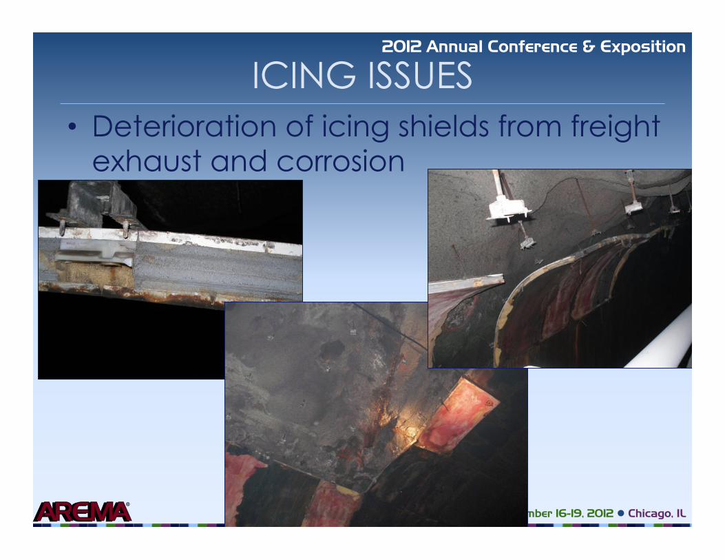
However, after 15 years of operation, the existing icing shields were deteriorating and the
track side of the sheets and the hanger screws were intensely rusted (Figure 4). The deterioration
reached a point at which individual panels started falling off and the track side steel sheet
© 2012 AREMA
completely delaminated from the polyurethane insulation plank. This deterioration of the track
side appeared to result from seepage into the polyurethane core from the joints in the panels and
possibly from the locomotive exhaust gas. Existing shields were located at the following
locations within the tunnel (Figure 5): Station 24+32 to 25+00, Station 32+04 to 34+71, and
Station 35+50 to 35+53. In 2009, the existing shields at Stations 24+32 to 25+00 and 35+50 to
35+53 were removed because of their deteriorated condition.
With extreme winter conditions and record freezing temperatures in 2009 and 2010, large
icicles developed within Station 24+32 to 25+00 from existing seeps within the tunnel (Figure
6). The icicles were large enough that NSR personnel were required to remove them every other
day to limit hazards to rail traffic. Such hazards consist of penetrating or damaging of rail cars,
including possibly the windshield of a passing engine; reduction of clearances leading to speed
restrictions; and possible derailment if ice built up over the track structure because of poor
drainage. Because of the high volume of rail traffic in the Allegheny Tunnel, derailment was less
of an issue. Of bigger concern was damage to rail cars, clearance restrictions, the time required
to remove the icicles, and hazards that NSR personnel faced during ice removal.
Icicles also have a long-term impact on structure components within tunnels. Such impact
includes the loss of integrity of the shotcrete tunnel lining, ballast contamination, and unplanned
additional weight on utility lines. Over time, freezing and thawing of water in the shotcrete lining
can cause consequent cracking in the shotcrete, especially if the shotcrete was applied
improperly with subsequent voids or had a poor mix design. Additional cracking in the shotcrete
allows not only for more water to seep through the liner, but reduces the structural integrity
allowing for a greater chance of rock fall. Icicles can also introduce waterlogging and clogging
of the track ballast, which can lead to difficulties with track maintenance. Utilities within the
© 2012 AREMA

tunnel may experience heavier loads than expected and could be damaged or collapse from the
weight.
A site visit was conducted in January 2010 by NSR and Jacobs Associates to address the
replacement of the existing icing shields. The site visit confirmed that the existing tunnel
shotcrete lining was still in good condition. However, in addition to the presence of large icicles,
additional observations revealed six ruptured drainage bladders within the shotcrete liner, little to
no shotcrete present on the existing steel sets at the east portal, and missing bulkheads on
existing icing shields.
ICING SHIELD DESIGN
After reviewing the condition of the existing icing shields and alternatives to replace it, a
similar passive system was designed to control the icing condition at the same locations as the
existing icing shields (Figure 5). The new passive icing system design (Figure 7) consisted of
steel sets spaced evenly on center anchored into the existing concrete footings; between the steel
sets was a layered arrangement of components. This arrangement, going from the field side to
the track side, consisted of a drainage mat and two layers of insulation planks (Ethafoam 220 - a
closed-cell polyethylene). The track side of the steel sets and the insulation planks were covered
with galvanized metal Stay Form and a 2-inch (50 mm) layer of fiber-reinforced microsilica
shotcrete.
This shotcrete layer allowed not only protection of the insulation planks from locomotive
exhaust gas, but also helped form an airtight system to help contribute to the effectiveness of the
icing shield system. This airtight system can be compared to the insulation of an attic or
basement of a house - air does not circulate but maintains heat and acts as an insulator. The
shotcrete was limited to a 2-inch thickness because of clearance concerns. Along with the icing
© 2012 AREMA
shield, a drainage system was included in the design to collect the water seeping from the tunnel
liner and direct it into the existing invert drains that would eventually take it out of the tunnel.
Although the icing shield system was designed to inhibit ice formation, the steel sets
were designed for varying loading conditions, including ice formation located universally along
the entire span of the icing shield, along half of the icing shield, and along one-third of the icing
shield. The geometry of the steel sets was determined based on typical steel set geometry used in
tunnels while also complying with the tunnel clearance requirements: two column sections and
two arch sections with a single radius of curvature. The connections were typical steel set
connections with steel plates and threaded bolts at the spring line and crown. All of the steel
elements were required to be corrosion protected.
In order for the icing shields to be successful at inhibiting ice formation, adequate
thermal resistance (R-value) and an adequate drainage system were needed. The R-value is a
measure used to determine the required insulation parameters for specific structures in a climate
location. For our icing shield design, the required R-value came from the 2009 International
Energy Conservation Code (IEEE) (2) for Cambria County, Pennsylvania, which is identified as
Climate Zones 4 and 5. The required R-value range was determined to be a minimum of
19 ft2·F°·h/Btu to a conservative value of 38 ft2·F°·h/Btu for ceilings. The R-value for our system
was determined by the Colorado Energy Organization values for material properties (3), shown
in Table 1.
The total R-value of 34 ft2·F°·h/Btu was adequate because it is within the required range
stated above and some of the materials that may be contributing to the thermal resistance were
not used in determining the design value, such as the drainage mat and galvanized steel.
© 2012 AREMA

The drainage system is extremely important for the icing shields to be effective since
blocked drainage could impose hydraulic loads on the shields. The drainage system ensures that
no water gets through the icing shields and over to the track side of the tunnel. Therefore, the
design drainage path allowed for water to seep from the tunnel liner to the back of the drainage
mat, down to the concrete footing, through the PVC piping, and to the existing drains.
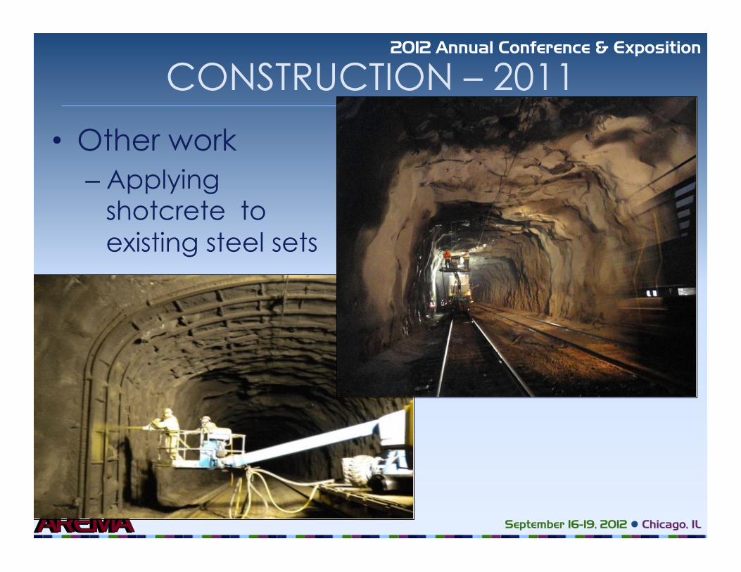
Additional design work included in the icing shield replacement project included
applying fiber-reinforced shotcrete over the exposed steel sets near the east portal and replacing
the ruptured drainage bladders (as shown in the locations in Figure 5). The drainage bladder
replacement design consisted of a dimple board drainage mat pinned to the existing tunnel wall,
covered with a single 2-inch insulation plank, then a layer of Stay Form, and finally a 2-inch
layer of fiber-reinforced shotcrete.
CONSTRUCTION
The design work was completed in June 2010 and put out to bid by NSR. LRL
Construction Company of Tillamook, Oregon, was the winning bidder, and construction of the
new icing shields began in late September 2010. LRL’s construction plan included assembling
partial sections of the icing shields (up to five vertical posts of the steel sets with insulation
planks and drainage mat [Figure 8]) in the staging area and then moving the partial section into
the tunnel for installation.
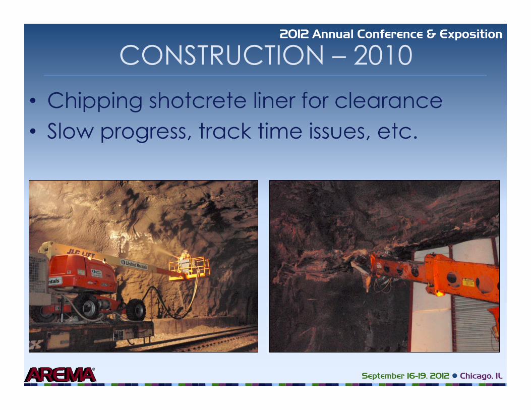
Some excavation of the shotcrete liner and bedrock was required to obtain adequate
clearance to place the steel sets. Unfortunately, the rock excavation was slow and time
consuming, and track time was limited. A large part of the construction work was performed
over one track at a time while traffic was maintained on the second track. Because of the increase
in train traffic for Christmas (NSR’s UPS season), no construction could be conducted between
© 2012 AREMA

November 15 to January 1 since UPS trains are guaranteed to be on time during this period and
cannot be held up for construction. Therefore, the 2010 construction season consisted of
installation of icing shields between Stations 24+32 to 25+00 and 35+50 to 35+53 (Figure 8), but
there was not enough time to replace the icing shields between Stations 32+04 and 34+71 or to
complete the drainage bladder replacements and strip drain installations. These items were left
for the 2011 construction season (Figure 10).
Before construction restarted in 2011, several modifications of the icing shield design
were made to improve constructability and performance. These modifications were based on
observations during the 2010 construction season and the winter of 2010. During the winter of
2010, a solitary leak was observed in the crown of a new ice shield. This leak was likely because
the plastic used for the drainage mat on the field side of the icing shields was often blown into
the rock above it when a train passed. This created pinholes in the mat. Therefore, thicker pond
liner was required for the drainage mat, to make it heavier and much less susceptible to damage.
Other design modifications included:
• Altering the shape of the steel sets to reduce /minimize the amount of rock
excavation required
• Increasing the thickness of the shotcrete in the crown of the icing shields between
the centerlines of the two tracks for both the 2010 and 2011 icing shield
installations
• Adding a waterproofing additive to the shotcrete
• Replacing the drainage pipes installed in 2010 that had shattered over the winter
because of ice buildup and insulating the new drainage pipes
© 2012 AREMA
• Limiting the drainage bladder replacements to only the portions of the bladders
that were ripped and deteriorating
Construction continued in early April 2011 with the contractor removing the old icing
shields between Stations 32+04 and 34+71. The design modifications were effective, and
construction proceeded smoothly with the only major issue being track time availability. Since
traffic was heavy and track time limited, the construction schedule had to be extended.
Construction of the icing shields and repair to the bladders were completed in late August 2011.
However, because of extensive seepage and icing concerns at the east end of the tunnel, the
contractor was remobilized to the tunnel in late October to implement additional leak repairs.
The worst leaks were diverted into PVC pipes by concentrating the flow at one location using a
hydrophilic cement. The pipes were then insulated with insulating foam sealant and an insulation
plank, which was secured in place with metal flashing. Minor leaks were plugged with
hydrophilic cement.
Final shotcrete application is scheduled for June 2012.
CONCLUSION
The final inspection of the 2011 work in Allegheny Tunnel was performed by the railroad
on November 16, 2011, after a week of rain. The seepage control measures were working
effectively. NSR personnel checked the tunnel periodically over the winter, and the icing shields
were found to be performing satisfactorily.
Key lessons learned during this project included:
• The importance of good survey data. A clearance survey was not performed
during the design phase in 2010 because of time and budget constraints. The rock
© 2012 AREMA

excavation during the 2010 construction season was at least partially due to the
combination of a lack of good survey data and the irregular tunnel perimeter.
• Understanding the effects of material substitutions. At the start of construction in
2010, the contractor requested substitution of the thinner plastic for the pond liner
drainage mat because it was more readily available and easier to work with.
Unfortunately, the plastic was easily torn and, with the limited track time
available, was often placed behind the steel sets but left unprotected, causing it to
be blown against the rock surface. The pond liner used in 2011 was far more
successful.
• The benefits of good coordination between the contractor and the flaggers. Since
track time was always limited, a great deal of the work was performed on one
track at a time.
The replacement of the icing shields, repair of the drainage bladders and installation of
additional seepage control measures have successfully reduced icing issues in Allegheny Tunnel,
which is subject to harsh winter conditions. Observing construction issues during the 2010
construction season and the performance of the icing shields during the winter of 2010 allowed
the designers to make design modifications for the 2011 construction season that improved
constructability and overall performance of the icing shields.
ACKNOWLEDGMENTS
The authors thank Norfolk Southern Railway for its assistance in preparing this article. In
addition, thanks are also due to the members of the design and construction team: Jacobs
Associates, LRL Construction, and NSR Division Engineer Craig Webb, Retired Assistant Division
© 2012 AREMA

Engineer Jim Rockney, Bridge Supervisor Dwayne Meadows, and the NSR flagmen for their
contribution to the project.
REFERENCES
1. Historic American Engineering Record. 1993. Pennsylvania Historic Railroad Bridges Recording Project, HAER No. PA-515.
2. International Energy Conservation Code (IECC). 2009. http://energycode.pnl.gov/
EnergyCodeReqs.
3. Colorado Energy Organization, http://coloradoenergy.org/procorner/stuff/r-values.htm.
4. Gallitzin Tunnels Park & Museum, http://www.gallitzin.info/tunnels.php. LISTING OF TABLE AND FIGURE CAPTIONS
Table 1. Material R-value Properties for the Allegheny Tunnel icing shields
Figure 1. Map of Pennsylvania showing location of Allegheny Tunnel in Gallitzin.
Figure 2. Construction at the west portal of Allegheny Tunnel for the double stack/double track project (4). Figure 3. Existing icing shields near the west portal, including the plywood bulkhead and the adjacent shotcrete tunnel liner. Figure 4. Deterioration of existing icing shields.
Figure 5. Allegheny Tunnel stationing and locations of icing shields.
Figure 6. Icicles observed within tunnel lining where icing shields deteriorated in January 2010.
Figure 7. Layered passive icing system design.
Figure 8. Installation of icing shields between Stations 24+32 and 25+00.
Figure 9. Installation of drainage mats in areas of heavy seepage.
Figure 10. Applying shotcrete to the newly installed icing shields between Stations 32+04 to 34+71.
© 2012 AREMA

TABLES
© 2012 AREMA

TABLE 1. Material R-value Properties for the Allegheny Tunnel Icing Shields
Material R-Value
(ft2·F°·h/Btu) / thickness (3)
Thickness in Allegheny Design
Total R-Value (ft2·F°·h/Btu)
Insulation planks 2.3 / inch 3 inches 6.9
Shotcrete 0.08 / inch 2 inches 0.16
Air Space (air space between the tunnel sidewall and icing shields) 1.0 / 0.5 to 4 inches Approx. 24 inches
Ranges 48 to 6 (Average 27)
TOTAL 34
© 2012 AREMA

FIGURES
© 2012 AREMA

Figure 1. Map of Pennsylvania showing location of Allegheny Tunnel in Gallitzin.
Figure 2. Construction at the west portal of Allegheny Tunnel
for the double stack/double track project (4).
© 2012 AREMA
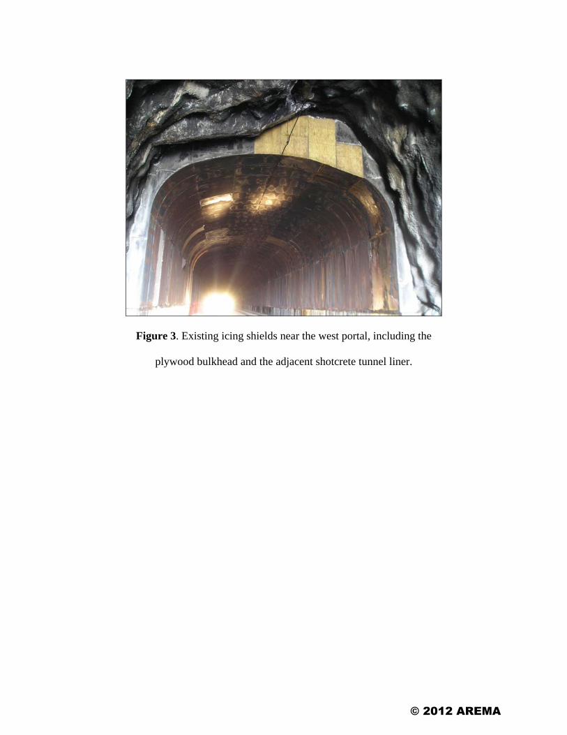
Figure 3. Existing icing shields near the west portal, including the
plywood bulkhead and the adjacent shotcrete tunnel liner.
© 2012 AREMA
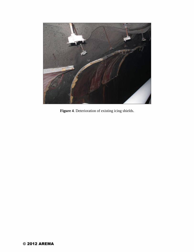
Figure 4. Deterioration of existing icing shields.
© 2012 AREMA
Figure 5. Allegheny Tunnel stationing and locations of icing shields.
© 2012 AREMA

Figure 6. Icicles observed within tunnel lining where icing shields deteriorated in January 2010.
© 2012 AREMA

Figure 7. Layered passive icing system design.
Figure 8. Installation of icing shields between Stations 24+32 and 25+00.
© 2012 AREMA

Figure 9. Installation of drainage mats in areas of heavy seepage.
Figure 10. Applying shotcrete to the newly installed icing shields
between Stations 32+04 to 34+71.
© 2012 AREMA
September 16-19, 2012 l Chicago, IL
2012 Annual Conference & Exposition
Passive Icing Shields for Railroad Tunnel in Gallitzin, PA
R. Brown, Norfolk Southern Railway P. Campbell, J. Schrank, Jacobs Associates
AREMA 2012 Annual Conference & Exposition Chicago, IL September 16–19, 2012

September 16-19, 2012 l Chicago, IL
2012 Annual Conference & Exposition
OUTLINE Overview Project Background Icing Issues Icing Shield Design Construction Conclusion
Permission to use photos by Gallitzin Tunnels Park & Museum
September 16-19, 2012 l Chicago, IL
2012 Annual Conference & Exposition
OVERVIEW Allegheny Tunnel – Gallitzin, PA
Photos by Google Earth Professional, 2012
ALTOONA
GALLITZIN
ALLEGHENY TUNNEL
ALIGNMENT
September 16-19, 2012 l Chicago, IL
2012 Annual Conference & Exposition
PROJECT BACKGROUND Train traffic – 40 to 50 freight trains and Amtrak each day

September 16-19, 2012 l Chicago, IL
2012 Annual Conference & Exposition
PROJECT BACKGROUND Constructed in 1851 & 1854 (Penn RR) – 3,600 feet long, single track – Brick arch & masonry sidewalls, sandstone
portals

September 16-19, 2012 l Chicago, IL
2012 Annual Conference & Exposition
PROJECT BACKGROUND Double track/double stack construction from 1994 to 1996 (CONRAIL) – Removal of existing lining, relined with rock
bolts and shotcrete lining – Cast-in-place concrete portals

September 16-19, 2012 l Chicago, IL
2012 Annual Conference & Exposition
ICING ISSUES Condition of the tunnel – Significant seepage and
freezing

September 16-19, 2012 l Chicago, IL
2012 Annual Conference & Exposition
ICING ISSUES
2011 Construc�on
267 �
2010 Construc�on
4 �
2010 Construc�on
68 �
September 16-19, 2012 l Chicago, IL
2012 Annual Conference & Exposition
ICING ISSUES Icing Shields originally installed1996 Drainage ditches on either side of tunnel
September 16-19, 2012 l Chicago, IL
2012 Annual Conference & Exposition
ICING ISSUES Deterioration of icing shields from freight exhaust and corrosion

September 16-19, 2012 l Chicago, IL
2012 Annual Conference & Exposition
ICING SHIELD DESIGN Passive system – Free-standing structure – Steel sets, insulation sheets, drainage mat – Shotcrete layer

September 16-19, 2012 l Chicago, IL
2012 Annual Conference & Exposition
ICING SHIELD DESIGN
Insulation Thermal Resistance (R-value)
Rairspace Rinsula�on Rshotcrete
𝑅𝑅𝑅𝑅𝑅𝑅𝑅𝑅𝑅𝑅𝑅𝑅𝑅𝑅= 𝑅𝑅𝑅𝑅𝑅𝑅𝑅𝑅𝑅𝑅𝑅𝑅𝑅𝑅𝑅𝑅𝑅𝑅𝑅𝑅+ 𝑅𝑅𝑅𝑅𝑅𝑅𝑅𝑅𝑅𝑅𝑅𝑅𝑅𝑅𝑅𝑅𝑅𝑅𝑅𝑅𝑅𝑅𝑅𝑅+ 𝑅𝑅𝑅𝑅𝑅𝑅𝑅𝑅𝑅𝑅𝑅𝑅𝑅𝑅𝑅𝑅𝑅𝑅𝑅𝑅𝑅
Material R-‐Value
(�2·∙F°·∙h/Btu) / thickness
Thickness in Allegheny Design
Total R-‐Value
(�2·∙F°·∙h/Btu)
Insula�on planks 2.3 / inch 3 inches 6.9 Shotcrete 0.08 / inch 2 inches 0.16 Air Space (air space between the tunnel sidewall and icing shields)
1.0 / 0.5 to 4 inches
Approx. 24 inches
Ranges 6 to 48
(Avg. 27) TOTAL 34
Tunnel sidewall
Track side
Air Space
Rtotal = 34 >19 (IEEE for Cambria County,
PA Climate 4&5)

September 16-19, 2012 l Chicago, IL
2012 Annual Conference & Exposition
ICING SHIELD DESIGN
Drainage System – Pond liner – PVC piping – Cold-weather
insulation
Photo by Firestone Pond Liner, 2012

September 16-19, 2012 l Chicago, IL
2012 Annual Conference & Exposition
CONSTRUCTION - 2010
Construction between Sept – Nov 2010 – Station 24+32 to 25+00 = 68 feet – Station 35+50 to 35+54 = 4 feet – Replacing drainage bladders
September 16-19, 2012 l Chicago, IL
2012 Annual Conference & Exposition
CONSTRUCTION – 2010
Chipping shotcrete liner for clearance Slow progress, track time issues, etc.

September 16-19, 2012 l Chicago, IL
2012 Annual Conference & Exposition
CONSTRUCTION – 2010
Shotcrete applied to Icing Shield and Bladders

September 16-19, 2012 l Chicago, IL
2012 Annual Conference & Exposition
CONSTRUCTION – 2011 Construction restart in May 11 – Aug 11 – Design Alterations:
Redesign of steel set geometry Drainage mat material substitution Drainage pipe insulation plan
– Station 32+04 to 34+71 = 267 feet
– Replacing drainage bladders

September 16-19, 2012 l Chicago, IL
2012 Annual Conference & Exposition
CONSTRUCTION – 2011
September 16-19, 2012 l Chicago, IL
2012 Annual Conference & Exposition
CONSTRUCTION – 2011
Other work – Applying
shotcrete to existing steel sets

September 16-19, 2012 l Chicago, IL
2012 Annual Conference & Exposition
CONCLUSION
Inspected November 16, 2011 Performed satisfactory throughout winter 2011 Key lessons learned: – Survey information – Understanding effects of materials – Importance of good coordination and
communication
September 16-19, 2012 l Chicago, IL
2012 Annual Conference & Exposition
CONCLUSION
NSR, Jacobs Associates, LRL Construction, NSR Division Engineer Craig Webb, Retired Assistant Division Engineer Jim Rockney, Bridge Supervisor Dwayne Meadows, NSR Flagmen, and the Gallitzin Tunnels Park & Museum
Thank you to the following:

September 16-19, 2012 l Chicago, IL
2012 Annual Conference & Exposition
QUESTIONS?