Embed Size (px)
Citation preview

C-CL1-6-C9764-A INA-1603 Printed in Japan (IP)
New publication effective Mar. 2016.Specifications are subject to change without notice.
2016
Eco Changes is the Mitsubishi Electric Group’s environmental statement,and expresses the Group’s stance on environmental management. Through a wide range of businesses, we are helping contribute to the realization of a sustainable society.
Visit our website at:http://www.MitsubishiElectric.com/elevator/
PASSENGER ELEVATORS

The name says it all. An affordable standard elevator that is stylish, safe and incorporates
advanced technologies that ensure smart operation that saves energy every day.
No wonder our new compact elevator joins the NEXIEZ-Series.
The elevator’s simple design complements virtually all architectural styles, and the selection of colors
available is equally impressive. Additionally, enjoy excellent cost savings, speedy delivery,
and the unwavering safety inherent of Mitsubishi Electric elevators.
Enjoy a safe, stylish and smart lifestyle with NEXIEZ-S.
Modern & Fun
1 2
3
Based on our policy, “Quality in Motion”,
we provide elevators and escalators that will
satisfy our customers with high levels of
comfort, efficiency, ecology and safety.
Principle
We strive to be green in all of our business activities.We take every action to reduce environmental burden during each process of our elevators’ and escalators’ lifecycle.
Contents
Space-saving 5
Safety and Comfort 6
Car Designs 7
Hall Designs 11
EN81-70 Compliance 12
Materials and Colors 13
Features 14
Basic Specifications 15
Important Information on Elevator Planning 17
4

Multiple infrared-light beams cover some 1800mmin height of the doors to detect passengers orobjects as the doors close.
One infrared-light beam covers the full width of the doors as they close to detect passengers or objects.
As all equipment is installed within the hoistway, there are fewer restrictions on building design except for the actual space required for the hoistway. Architects and interior designers have more design freedom.
5 6
Upon power failure, the car automatically moves to the nearest floor using a rechargeable battery to facilitate the safe evacuation of passengers.
When the car is about to arrive at the floor, the hall button flashes to inform passengers of car arrival.
Mitsubishi Emergency Landing Device (MELD) (Optional)
Features to help everyone travel safely and comfortably
Multi-beam Door Sensor (Optional)
Click-Type Hall Call Button with Hall Lantern Function (HBEHL)Machine-room-less Elevators
Safety Ray (SR)
Doors openDetects power supply failure
Turns on emergency light
Confirms safety
Moves to the nearest floor
Hall call registration Before car arrival
Safety and ComfortSpace-saving
1
2
3 5
4

Car Designs
7 8
Note:* Flooring PR812 is also available as a standard color.
Standard Car Design
Wall (side)Wall (rear)Front return panelFlooring
Stainless-steel, hairline-�nishStainless-steel, hairline-�nishStainless-steel, hairline-�nishDurable vinyl tiles (PR801*)
Car Design Example
Wall (side)Wall (rear)Front return panelFlooring
Painted steel sheet (Y014)Stainless-steel, hairline-�nishStainless-steel, hairline-�nishDurable vinyl tiles (PR812)
Simple yet stylish car designs attractively compliment any interior, providing easy coordination and freedom of application to most any building design.N700 White downlight design utilized to create new elevator car interior look with elegant lighting atmosphere
and sophisticated appearance.L 700Standard
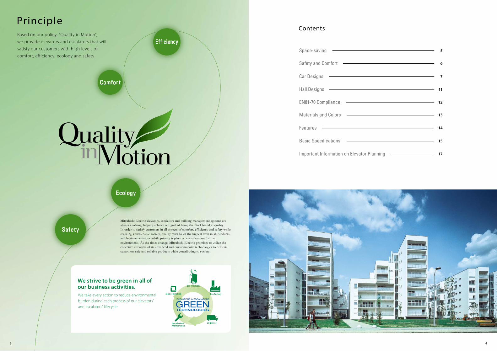
Car Designs
Car Operating Panels
Handrail and Mirror Mirror
Handrail
CBV1-M760(without intercom and AAN features)
Side view CBV1-M760(with intercom
and/or AAN features)
CBV1-M762(for EN81-70)
YZ-52AN
YH-59S(Stainless-steel, hairline-�nish)
Y014 Y116 Y033
Y014 Y116 Y033
Stainless-steel,hairline-�nish
Combination wallSide: Painted steel sheetRear: Stainless-steel, hairline �nish
Painted steel sheet
9 10
Note:* Segment LED indicators cannot display some letters of alphabet. However, to display “Z” in particular, an equivalent
car operating panel with a dot LED indicator can be arranged. Please consult our local agents for details.
Segment LED indicators *2
The feeling of spaciousness create by the SUS and painted wall combinations is complemented by new lighting �xtures that produce an elegant, comfortable car atmosphere.Color Variations
Standard
Car operating panelMirror
Hall button *
Hall positionindicator and button *
Handrail
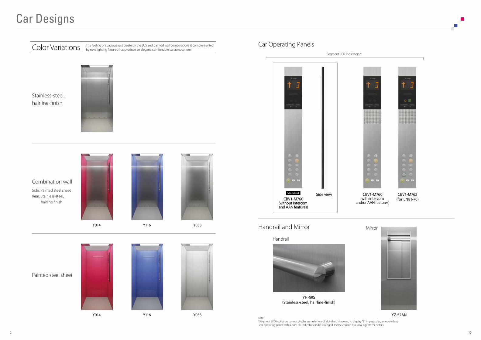
Hall Buttons Hall Position Indicators and Buttons *1
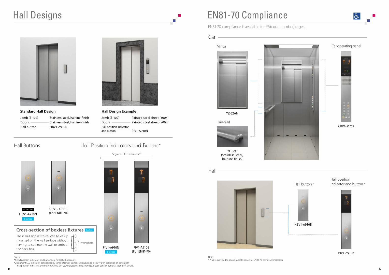
Hall DesignsEN81-70 compliance is available for P6(code number)cages.
EN81-70 Compliance
CBV1-M762
PIV1-A910B(For EN81-70)
PIV1-A910N
HBV1- A910B(For EN81-70)HBV1-A910N
YZ-52AN
YH-59S(Stainless-steel, hairline-�nish)
HBV1-A910B
PIV1-A910B
11 12
Notes:*1: Hall position indicators and buttons are for lobby �oors only.*2: Segment LED indicators cannot display some letters of alphabet. However, to display “Z” in particular, an equivalent
hall position indicators and buttons with a dot LED indicator can be arranged. Please consult our local agents for details.
Car
Hall
Jamb (E-102)DoorsHall button
Stainless-steel, hairline-�nishStainless-steel, hairline-�nishHBV1-A910N
Jamb (E-102)DoorsHall position indicatorand button
Painted steel sheet (Y004)Painted steel sheet (Y004)
PIV1-A910N
Standard Hall Design Hall Design Example
Segment LED indicators *2
Standard
Boxless
Boxless
Note:* A slit is provided to sound audible signals for EN81-70-compliant indicators.
BoxlessCross-section of boxless �xturesThese hall signal fixtures can be easily mounted on the wall surface without having to cut into the wall to embed the back box.
Wiring hole

Car
Hall
Materials and Colors Features
13 14
Feature Mitsubishi Electric standard
Earthquake Emergency Return
Fire Emergency Return
Firefighters' Emergency Operation
Mitsubishi Emergency Landing Device
Operation by Emergency Power Source --- Automatic
Optional
Optional
Optional
Optional
Optional
Optional
Optional
-
Optional
Optional
Note:* When the elevator complies with EN81-70, AAN-G feature is required. (AAN-B is not applicable)
Y033 Y014Y116
Y033(N700)
Y055(L700)
Ceiling
Painted steel
Flooring
Walls and Doors
PR801 PR812
Durable vinyl tiles
Stainless-steel Painted steel
Hairline-finish
Y033 Y004
Jamb and Doors
Stainless-steel Painted steel
Hairline-finish
■ EMERGENCY OPERATIONS AND FEATURES
Feature
Automatic Door Speed Control
Door Load Detector
Door Nudging Feature --- With Buzzer
Door Sensor Self-diagnosis
Multi-beam Door Sensor (without Safety Door Edge)
Reopen with Hall Button
Repeated Door-close
Safety Ray
Standard
Standard
Standard
Standard
Optional
Standard
Standard
Standard
Standard
Standard
Standard
Standard
Standard
Standard
Standard
-
■ DOOR OPERATION FEATURES
Feature
Car Call Canceling
Car Fan Shut O� --- Automatic
Car Light Shut O� --- Automatic
False Call Canceling --- Car Button Type
Independent Service
Next Landing
Overload Holding Stop
Safe Landing
Standard
Standard
Standard
Standard
Standard
Standard
Standard
Standard
Standard
Standard
Standard
Standard
Standard
Standard
Standard
Standard
■ OPERATIONAL AND SERVICE FEATURES
Feature
Basic Announcement
Click-type Hall Call Button with Hall Lantern Function
Emergency Bell
Emergency Car Lighting
Inter-communication System
Voice Guidance System
Optional
Standard
Standard
Optional
Optional
Optional
Optional *
Standard
Optional
Standard
Standard
Optional *
■ SIGNAL AND DISPLAY FEATURES
DSAC
DLD
NDG
DODA
-
ROHB
RDC
SR
Abbreviation
CCC
CFO-A
CLO-A
FCC-P
IND
NXL
OLH
SFL
Abbreviation
AAN-B
HBEHL
EMB
ECL
ITP
AAN-G
Abbreviation
EER-S
FER
FE
MELD
OEPS-SA
Mitsubishi Electric standard
Mitsubishi Electric standard
Mitsubishi Electric standard
Abbreviation
EN81-1
EN81-1
EN81-1
EN81-1

Minimum overhead(mm)
OH
Travel(m)TR
Pit depth(mm)
PD
Minimumfloor to floor height
(mm)
Maximumnumberof floors
2600*11100 - 15003500103 - 30
Shown for code number P4
15 16
Shown for code number P6
Basic Specifications
Reaction loads (kN)
Rail Buffer
P1 P2
14
16
320
450
4
61.0
14
16
7
8
11
12
38
47
32
381000×1250
800×1100
Door elevation (section A-A) Hoistway entranceDoor plan (section B-B)
Feeder Size Calculation
Power Feeder Data
Entrance Layout
FLU: current during upward operation with full load at a power supply voltage of 400V.FLAcc: current while accelerating with full load at a power supply voltage of 400V.Note: If power supply voltage (E) is a value other than 400V, FLU current and FLAcc current are obtained via the following formula.
(FLU/FLAcc current (A) at E (V)) = (Current at 400V) × (400/E (V))
Capacity(kg)
Ratedspeed
(m/sec)
Current at 400V
FLU (A) FLAcc (A)Breaker in
control panel(A)
2 6 11 10 3 580
Motoroutput
(kW)
Capacity ofpower supply
(kVA)
Heatemissions
(W)
3201.0
2.8 8 14 10 3 740450
● The feeder must be able to withstand continuous flow of the following current at an ambient temperature of 40°C.
Applicable StandardsNEXIEZ-S complies with Mitsubishi Electric standard*2 and/or EN81-1.For details of compliance, please consult our local agents.
Notes:*1: The minimum floor to floor distance from the top to the next service floor is 2800mm.*2: Based on, but not fully complying with the Building Standard Law of Japan, 2009.
FLU (A) ≦ 50A ------ 1.25 × FLU (A)(FLU (A): current during upward operation with full load at a power supply voltage of E (V ))
The wire length for the feeder size must be calculated using the following formula.Wire length (m) ≦ Coefficient* × E (V)/FLAcc (A)(E: power supply voltage (V))(FLAcc (A): current while accelerating with full load at a power supply voltage of E (V ))
* Refer to the table below for coefficients.
● The current size of the grounding wire is determined according to the current rating of the NF breaker on the power source side.● The current rating of the NF breaker on the power source side should be one level larger than that on the control panel side.
Feeder size (mm2)Coe�cient
3.5
6.3
5.5
9.7
Horizontal Dimensions
Vertical Dimensions
Reaction Loads
Hoistway Plan Hoistway Section
[ Terms of the table]• The contents of this table are applied to standard specifications only. Please consult our local agents for other specifications.• Rated capacity is calculated at 75kg per person, as required by EN81-1.• 2S: 2-panel side sliding doors.• Minimum hoistway dimensions (AH and BH) shown in the table are after waterproofing of the pit and do not include plumb tolerance.• This table shows specifications without the fireproof landing door and counterweight safety.
Codenumber
Doortype
Numberof
persons
Car internaldimensions
(mm)AAxBB
Entrance width(mm)
JJ
Minimum hoistway dimensions (mm)
AHxBH
Ratedcapacity
(kg)
Ratedspeed
(m/sec)
1350 x 1550800 x 1100P4 3202S
7004
1550 x 16501000 x 1250P6 450 80061.0
Control panel(Top floor only)20
0
400 100
3810
50
Entrance width: JJ 100
150
Fini
shW
all
Finished wall(by owner)
115
125
B
B
Entrancewidth:
JJ
Keyhole
A
Con
trol p
anel
(Top
floo
r onl
y)
150
Ent
ranc
e he
ight
: 210
012
00(1
050
for E
N81
-70)
Finishedfloor level
A
Ent
ranc
e he
ight
: 210
0
60
60
Con
trol p
anel
(Top
floo
r onl
y)
1070
Control panel(Top floor only)
JJ
AA
BB
AH
BH
R4
R3
P2
R2 R1P1/2 P1/2
JJ
AA
BB
AH
BH
Control panel(Top floor only)
R4
R3
P2
R2 P1/2 R1P1/2
Ent
ranc
e he
ight
: HH
2100
(sta
ndar
d)
Cei
ling
heig
ht22
00 (s
tand
ard)
Ove
rhea
d: O
HTr
avel
: TR
Floo
r to
floor
hei
ght
Pit
dept
h: P
D

Important Information on Elevator Planning
17 18
Work Not Included in Elevator Contract
Ordering InformationPlease include the following information when ordering or requesting estimates:• The desired number of units, speed and loading capacity• The number of stops or number of floors to be served• The total elevator travel and each floor-to-floor height• Operation system• Selected design and size of car• Entrance design• Signal equipment• A sketch of the part of the building where the elevators are to be installed• The voltage, number of phases and frequency of the power source for the motor and lighting
The following items are excluded from Mitsubishi Electric’s elevator installation work, and are therefore the responsibility of the building owner or general contractor: • Architectural finishing of the walls and floors in the vicinity of the entrance hall after installation has been completed.• Construction of hoistway designated by Mitsubishi Electric Corporation including illumination, ventilation and waterproofing.• Cutting the necessary openings and joists.• All other work related to building construction.• The power-receiving panel and the electrical wiring for illumination, plus the electrical wiring from electrical room to the power-receiving panel.• The laying of conduits and wiring between the elevator pit and the terminating point for the devices installed outside the hoistway, such as the
emergency bell, intercom, monitoring and security devices.• The power consumed in installation work and test operations.• All the necessary building materials for grouting in of brackets, bolts, etc.• The test provision and subsequent alteration as required, and eventual removal of the scaffolding as required by the elevator contractor, and any other
protection of the work as may be required during the process.• The provision of a suitable, locked space for the storage of elevator equipment and tools during elevator installation.• The security system, such as a card reader, connected to Mitsubishi Electric’s elevator controller, when supplied by the building owner or general
contractor.* Work responsibilities in installation and construction shall be determined according to local laws. Please consult our local agents for details.
Elevator Site Requirements• The temperature of the elevator hoistway shall be below 40˚C.• The following conditions are required for maintaining elevator performance.
a. The relative humidity shall be below 90% on a monthly average and below 95% on a daily average.b. Prevention against icing and condensation occurring due to a rapid drop in the temperature shall be provided in the elevator hoistway.c. The elevator hoistway shall be finished with mortar or other materials so as to prevent concrete dust.
• Voltage fluctuation shall be within a range of +5% to -10%.
C-CL1-6-C9764-A INA-1603 Printed in Japan (IP)
New publication effective Mar. 2016.Specifications are subject to change without notice.
2016
Eco Changes is the Mitsubishi Electric Group’s environmental statement,and expresses the Group’s stance on environmental management. Through a wide range of businesses, we are helping contribute to the realization of a sustainable society.
Visit our website at:http://www.MitsubishiElectric.com/elevator/
PASSENGER ELEVATORS