Embed Size (px)
Citation preview

Sebastian Schulze∗, Fred Compart∗, Andreas Richter∗, Petr A. Nikrityuk� andBernd Meyer∗∗ IEC, TU Bergakademie Freiberg, Germany� Department of Chemical and Materials Eng., UoA, Edmonton, Canada
Particle-resolved numerical study of char conversion processesconsidering conditions in the British-Gas-Lurgi (BGL) gasifier
June 13, 2016
International Freiberg Conference, 13–16 June 2016, Cologne, Germany

Content
Introduction & Motivation
CFD model
Validation: Air and 1 atm
Influence of packed-bed structure: Air and 1 atm
BGL conditions: Reducing atmosphere and 40 bar
Conclusion
TU Bergakademie Freiberg | IEC | S. Schulze et al. | Particle-resolved CFD-Study of Char Conversion | IFC 2016, Cologne, Germany | 2016-06-13 1/23

Introduction & Motivation
Introduction
The British Gas/Lurgi (BGL) gasifier with slag tapping poses advantages over the LurgiFixed-bed dry bottom gasificationa.
higher specific throughput
high carbon conversion
production of vitrified slag
much lower steam consumption
fines can be introduced via tuyeresa
Schmalfeld (Ed.), Die Veredelung und Umwandlung von Kohle, DGMK, 2008
TU Bergakademie Freiberg | IEC | S. Schulze et al. | Particle-resolved CFD-Study of Char Conversion | IFC 2016, Cologne, Germany | 2016-06-13 2/23

Motivation
The understanding of the phenomena occuring within the complex structure of themoving/fixed bed gasifiers is limited, especially in the part of the oxidation andgasification zones where conversion occurs rapidly.
Additionally, due to the harsh conditions (extreme high temperatures in and abovethe slag bath, 40 bar) data is difficult to access via measurementsa.
Thus, detailed numerical simulations can give insights of the processes as they act as’numerical experiment’.
aSchmalfeld (Ed.), Die Veredelung und Umwandlung von Kohle, DGMK, 2008
TU Bergakademie Freiberg | IEC | S. Schulze et al. | Particle-resolved CFD-Study of Char Conversion | IFC 2016, Cologne, Germany | 2016-06-13 3/23
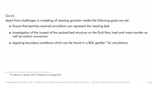
GoalsApart from challenges in modeling of reacting granular media the following goals are set:
Ensure that particle-resolved simulation can represent the reacting bed
Investigation of the impact of the packed-bed structure on the fluid flow, heat and mass transfer aswell as carbon conversion
Applying boundary conditions which can be found in a BGL gasifier1 for simulations
1M. Olschar, O. Schulze, 5th Int. Freiberg Conf., Leipzig 2012
TU Bergakademie Freiberg | IEC | S. Schulze et al. | Particle-resolved CFD-Study of Char Conversion | IFC 2016, Cologne, Germany | 2016-06-13 4/23

CFD model
AssumptionsApplying the pseudo-steady-state approach (PSS)2 following assumptions are introduced:
The particle shape is spherical.
The porosity of the particles is not taken into account, thus the intraparticle diffusion is neglected.
The particles consists of carbon only. The devolatilization is not included due to the steady-statecharacter .
The gas radiation is included
For 2-D simulation an axisymmetric domain is assumed.
The buoyancy effect is neglected.
2Amundson et al., Ind. Eng. Chemistry Fundamentals, 1980.
TU Bergakademie Freiberg | IEC | S. Schulze et al. | Particle-resolved CFD-Study of Char Conversion | IFC 2016, Cologne, Germany | 2016-06-13 5/23

Reactions
The chemistry is modeled using semi-global homogeneous and heterogeneous reactions3:heterogeneous (surface) reactions:
C +12
O2 → CO h0R1 = −9.2 MJ kg−1C (R1)
C + CO2 → 2CO h0R2 = 14.4 MJ kg−1C (R2)
C + H2O→ CO + H2 h0R3 = 10.9 MJ kg−1C (R3)
homogeneous (gas phase) reactions:
CO +12
O2 + H2O→ CO2 + H2O h0R4 = −10.1 MJ kg−1CO (R4)
CO + H2O→ CO2 + H2 h0R5 = −1.15 MJ kg−1CO (R5)
CO2 + H2 → CO + H2O h0R6 = 1.15 MJ kg−1CO (R6)
3Turns, An Introduction to Combustion, 2006.
TU Bergakademie Freiberg | IEC | S. Schulze et al. | Particle-resolved CFD-Study of Char Conversion | IFC 2016, Cologne, Germany | 2016-06-13 6/23

Validation: Air and 1 atm
Validation case set-up: Combustion of coke particles with preheated air4
Tab. 1: Parameters for simulation ofexperiments
Particle size 32 mmVoid fraction 0.4Inlet temperature 300, 478 and 700 KInlet gas composition
YO20.233
YH2O 0.007YN2
0.760Inlet mass flux 0.202 kg m−2s−1
sam
ple
ho
les
0.508 m
1.0
67
m
preheated air
product gas
steel grate
Fig. 1: Scheme of experimental fixed bedcombustion set-up
4Nicholls, Bulletin 378, Bureau of Mines, 1935.
TU Bergakademie Freiberg | IEC | S. Schulze et al. | Particle-resolved CFD-Study of Char Conversion | IFC 2016, Cologne, Germany | 2016-06-13 7/23

Results: Temperature and species distribution 1
Fig. 2: Temperature and O2 mass fraction contour plots
TU Bergakademie Freiberg | IEC | S. Schulze et al. | Particle-resolved CFD-Study of Char Conversion | IFC 2016, Cologne, Germany | 2016-06-13 8/23

Results: Temperature and species distribution 2
Fig. 3: CO2 and CO mass fraction contour plots
TU Bergakademie Freiberg | IEC | S. Schulze et al. | Particle-resolved CFD-Study of Char Conversion | IFC 2016, Cologne, Germany | 2016-06-13 9/23

Results: Comparison with experiments, 300 K
0 0.05 0.1 0.15 0.2 0.25 0.3z [m]
1500
1650
1800
1950
2100
2250
Tem
per
atu
re [
K]
gas temperature CFD
solid temperature CFD
temperature experiment
0 0.05 0.1 0.15 0.2 0.25 0.3z [m]
0
0.05
0.1
0.15
Xi [
-]
YCO
2
experiment
YO
2
experiment
YCO
2
CFD
YO
2
CFD
0 0.05 0.1 0.15 0.2 0.25 0.3z [m]
0
0.1
0.2
0.3
0.4
Xi [
-]
YCO
experiment
YCO
CFD
(a) (b) (c)
Fig. 4: Validation: Temperature (a), CO2 mole fraction (b) and CO mole fraction in dependence of height abovegrate. The different colors correspond to the inlet gas temperature. Results for 300 K are shown.
TU Bergakademie Freiberg | IEC | S. Schulze et al. | Particle-resolved CFD-Study of Char Conversion | IFC 2016, Cologne, Germany | 2016-06-13 10/23

Results: Comparison with experiments, 700 K
0 0.05 0.1 0.15 0.2 0.25 0.3z [m]
1500
1650
1800
1950
2100
2250
Tem
per
atu
re [
K]
gas temperature CFD
solid temperature CFD
temperature experiment
0 0.05 0.1 0.15 0.2 0.25 0.3z [m]
0
0.05
0.1
0.15
Xi [
-]
YCO
2
experiment
YCO
2
CFD
0 0.05 0.1 0.15 0.2 0.25 0.3z [m]
0
0.1
0.2
0.3
0.4
Xi [
-]
YCO
experiment
YCO
CFD
(a) (b) (c)
Fig. 5: Validation: Temperature (a), CO2 mole fraction (b) and CO mole fraction in dependence of height abovegrate. The different colors correspond to the inlet gas temperature. Results for 700 K are shown.
TU Bergakademie Freiberg | IEC | S. Schulze et al. | Particle-resolved CFD-Study of Char Conversion | IFC 2016, Cologne, Germany | 2016-06-13 11/23

Influence of packed-bed structure: Air and 1 atm
Grid generation for random packed bedFrom DEM simulation of particle sedimentation to representive geometry
(a)
(b)
(c)(d)
Fig. 6: Column of monodisperse particles from DEM simulation (a), Cutting-out representative volume 2.5dP × 2.5dP × 10dP (b),bridge at contact points5,6 dbridge = 0.125dP (c) and grid comprising of ca. 6 · 106 tetrahedral cells (d)
5Ookawara et al.,European Congress Chem.Eng. 2007.
6Dixon et al., Computers Chem.Eng, 2013.
TU Bergakademie Freiberg | IEC | S. Schulze et al. | Particle-resolved CFD-Study of Char Conversion | IFC 2016, Cologne, Germany | 2016-06-13 12/23
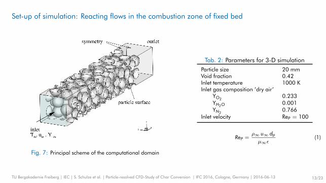
Set-up of simulation: Reacting flows in the combustion zone of fixed bed
Fig. 7: Principal scheme of the computational domain
Tab. 2: Parameters for 3-D simulation
Particle size 20 mmVoid fraction 0.42Inlet temperature 1000 KInlet gas composition ’dry air’
YO20.233
YH2O 0.001YN2
0.766Inlet velocity ReP = 100
ReP =ρ∞ u∞ dpµ∞ε
(1)
TU Bergakademie Freiberg | IEC | S. Schulze et al. | Particle-resolved CFD-Study of Char Conversion | IFC 2016, Cologne, Germany | 2016-06-13 13/23

Results: Velocity isosurfaces
Fig. 8: Isosurface of velocity magnitude of 3 m/s, the colour represents the gas temperature (K) for inlet gas composition ofYO2,∞= 0.233 and YH2O,∞= 0.001.
TU Bergakademie Freiberg | IEC | S. Schulze et al. | Particle-resolved CFD-Study of Char Conversion | IFC 2016, Cologne, Germany | 2016-06-13 14/23

Results: Flame propagation into the fixed bedComparison of random packed bed and simple cubic bed
(a) (b)
Fig. 9: Contour plot of gas temperature (K) at the symmetry planes for random fixed bed (a) and simple cubic packing (b) forinlet gas composition of YO2,∞= 0.233 and YH2O,∞= 0.001.
TU Bergakademie Freiberg | IEC | S. Schulze et al. | Particle-resolved CFD-Study of Char Conversion | IFC 2016, Cologne, Germany | 2016-06-13 15/23
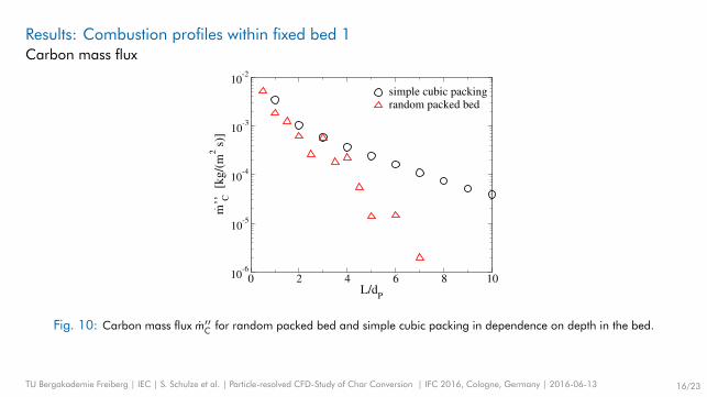
Results: Combustion profiles within fixed bed 1Carbon mass flux
0 2 4 6 8 10L/d
P
10-6
10-5
10-4
10-3
10-2
m.’’ C
[k
g/(
m2 s
)]
simple cubic packingrandom packed bed
Fig. 10: Carbon mass flux m′′C for random packed bed and simple cubic packing in dependence on depth in the bed.
TU Bergakademie Freiberg | IEC | S. Schulze et al. | Particle-resolved CFD-Study of Char Conversion | IFC 2016, Cologne, Germany | 2016-06-13 16/23

BGL conditions: Reducing atmosphere and 40 bar
Defining inflow conditionsBoundary conditions within oxidation and gasification zone from basic flow sheet simulation of IEC’s BGL gasifier7 with
AspenPlus.
Fig. 11: Flow diagram of BGL gasifier
Tab. 3: Inlet gas properties
Temperature 2673 KCO2 12.7 vol.-%H2O 18.8 vol.-%CO 52.2 vol.-%H2 11.1 vol.-%
7M. Olschar, O. Schulze, 5th Int. Freiberg Conf., Leipzig 2012
TU Bergakademie Freiberg | IEC | S. Schulze et al. | Particle-resolved CFD-Study of Char Conversion | IFC 2016, Cologne, Germany | 2016-06-13 17/23

Applying suitable high-pressure kinetics for char gasification
Tab. 4: Intrinsic reactivity data8
Reaction A0 [g/(m2 s atmn)] EA [kJ/mol] n
C + O2 3.0e+05 136.0 0.8C + CO2 4.0e+04 211.0 0.4C + H2O 3.0e+06 231.0 0.4
Discrepancy between intinsic reactivity data and solid particle with surface reactions
Calculation of effectiveness factor:
η = 1Φ
(1
tanh(3 Φ)− 1
3 Φ
)with Thiele modul Φ =
dP6
√(n+1) k S′′′ cn−1
i2 Deff
8Hla et al., Research Rep. 80, CSIRO, 2007.
TU Bergakademie Freiberg | IEC | S. Schulze et al. | Particle-resolved CFD-Study of Char Conversion | IFC 2016, Cologne, Germany | 2016-06-13 18/23

Results: Temperature and species distribution 1
Fig. 12: Temperature and CO2 mass fraction contour plots
TU Bergakademie Freiberg | IEC | S. Schulze et al. | Particle-resolved CFD-Study of Char Conversion | IFC 2016, Cologne, Germany | 2016-06-13 19/23
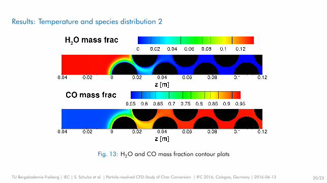
Results: Temperature and species distribution 2
Fig. 13: H2O and CO mass fraction contour plots
TU Bergakademie Freiberg | IEC | S. Schulze et al. | Particle-resolved CFD-Study of Char Conversion | IFC 2016, Cologne, Germany | 2016-06-13 20/23

Conclusion
Simulations of the validated particle-resolved CFD model were showingsignificantly different flame structure for the random packed bed compared tosimple cubic packing
Considering BGL-gasifer conditions, the carbon conversion in the fixed-bed ismore mass transfer limited than the combustion with air at the same particleReynolds number.
TU Bergakademie Freiberg | IEC | S. Schulze et al. | Particle-resolved CFD-Study of Char Conversion | IFC 2016, Cologne, Germany | 2016-06-13 21/23

Acknowledgement
This research has been funded by the Saxon State Ministry for Economic Affairs, Labour andTransport and the European Union in the frame of the project ’Schlackebadvergaser für die
Nutzung schwieriger Brennstoffe’ (project number P100092007).
TU Bergakademie Freiberg | IEC | S. Schulze et al. | Particle-resolved CFD-Study of Char Conversion | IFC 2016, Cologne, Germany | 2016-06-13 22/23

Thank you for your attention.
TU Bergakademie Freiberg | IEC | S. Schulze et al. | Particle-resolved CFD-Study of Char Conversion | IFC 2016, Cologne, Germany | 2016-06-13 23/23