Embed Size (px)
Citation preview
Ž .Powder Technology 105 1999 222–227www.elsevier.comrlocaterpowtec
Particle motion and energy distribution in tumbling ball mills
Anil Misra a,), Josephine Cheung b
a Department of CiÕil Engineering, UniÕersity of Missouri, 5605 Troost AÕenue, Kansas City, MO, 64110, USAb Grace Construction Products, 62 Whittemore AÕenue, Cambridge, MA, 02140, USA
Abstract
The charge flow characteristics and the local energy distributions have a profound influence on the comminution behavior in tumblingball mills. Computer simulation using a particle dynamics method offers a viable approach for investigating the flow and energydistribution characteristics within tumbling particulate media. In particle dynamics method, particulate systems are simulated by trackingparticles as they move in response to the forces developed through particle interactions. Utilizing this method, we focus upon a numericalinvestigation of flow and energy parameters of tumbling charge in ball mills. Specifically, we investigate the variation of these parameterswith the fundamental properties of mill–wall, clinker and ball-media particles. The properties considered in this work reflect particle andmill–wall elasticity and surface characteristics, such as, stiffness, elastic restitution and surface friction. q 1999 Elsevier Science S.A. Allrights reserved.
Keywords: Ball mills; Comminution; Computer simulations; Particle motions; Discrete Element Method
1. Introduction
Numerical tools that accurately replicate charge motionin ball mills are required for a better understanding of milloperations and from the view point of improving milldesign as well as milling processes. Computer simulationsbased upon particle dynamics methods, such as the distinct
w xelement method-DEM 1 and similar particle dynamicsw xmethods 2,3 , offer a viable approach for developing such
numerical tools. Applications of particle dynamics meth-ods in the study of processes within flowing particulatemedia have proliferated in recent years. These methods aredeemed especially advantageous as they directly considerphenomena that occur at particle-levels, which includeamong others, the inter-particle friction, adhesion, presenceof fluid and neighborhood structure. In these methods,individual particles are tracked by solving Newton’s equa-tions of motion as they move in response to the forcesdeveloped through particle interactions. Particle transla-tional as well as rotational degrees-of-freedom are allowedin these numerical simulations. Both normal and tangentialinteractions between particles and mill-wall are included.Energy losses are accounted through Coulombic friction inthe tangential direction and elastic restitution in the normaldirection. The numerical simulation model may be utilized
) Corresponding author
to evaluate a number of processes that occur within a ballmill, such as, charge mixing, charge motion, energy distri-bution and mill power expenditure.
In the discussions hereafter, we first describe the simu-lation theory as well as caveats associated with successfuland efficient numerical simulation with particle dynamics.Seminal equations and algorithmic issues associated withtime-integration and neighbor location that form the essenceof a particle dynamics simulation are presented. Subse-quently, selected results from the simulations are presentedto evaluate charge motion, charge mixing, velocity andkinetic energy distributions, mill power expenditure, andclinker breakage behavior.
2. Description of simulation theory
In the recent years, simulations of granular-flow usingparticle dynamics method have proliferated. The particledynamics simulation proceeds by considering the Newton’sequations of motions written for, say, the a-th particle inthe flowing granular media as,
na a a m a a a¨M x s f q f and I u¨ Ýi i i i
ms1
na m a m a m as e r f qm qm 1Ž .Ž .Ý i jk j k i i
ms1
0032-5910r99r$ - see front matter q 1999 Elsevier Science S.A. All rights reserved.Ž .PII: S0032-5910 99 00141-2
( )A. Misra, J. CheungrPowder Technology 105 1999 222–227 223
where, M a sparticle mass, I a sparticle moment of iner-tia, f a m scontact force, ma m scontact moment, f a si i i
body force, ma sbody moment, r a m svector connectingi i
particle centeroid to m-th contact, x a sparticle location,¨ i¨au sparticle orientation, and e spermutation symbol.i i jk
Note that the subscripts follow the usual tensor convention.While the essence of the particle dynamics method is the
Žsimultaneous solution of the above system of 6 N or 3 N.in 2-dimensions second-order ordinary differential equa-
tions, there are a variety of issues that may effect a particledynamics algorithm. The following three issues are partic-ularly germane to successful and efficient numerical simu-
Ž . Ž .lations, namely: 1 inter-particle force laws, 2 numericalŽ .time-integration schemes, and 3 neighbor location
schemes. Herein, we discuss these issues as they pertain toball mill simulations.
2.1. Inter-particle force laws
The inter-particle force laws determine the forces f a mi
and moments ma m produced by interaction of particle ai
and m. For ‘macroscopic’ frictional particles, it is commonto consider a Hertz–Mindlin type particle interactionmodel, wherein the particles are assumed to be rigid and
Ž w xconnected via contact springs and sliders see Ref. 4 for a.review . Further, in particle dynamics methods, contact
viscous dampers are typically considered for additionalenergy dissipating mechanism. In the subsequent discus-sions we consider, for convenience, forces along directionsof normal approach and tangential movement at particlecontacts, such that,
f a m s f a mna m q f a ms a m 2Ž .i n i s i
where na m is the unit vector along the direction of normali
approach, s a m is the unit vector along the direction ofi
tangential movement at the contact between particles a
and m, and f and f are normal and tangential forces atn s
the contact.Along the lines of Hertz–Mindlin models, with the
consideration of contact viscous damping, the contact nor-mal force f a m and the contact tangential force f a m aren s
obtained as follows:
f a m syK a mDa m yC a m x a m Da m )0,˙n n n n n n 3Ž .a m a mf s0, D F0n n
and
a m ea m < ea m < < a m <f ssgn f min f ,m f 4Ž .Ž . Ž .s s s n
where
f ea m s f a m qK a m x a m 5Ž .˙s s s s
where K , K scontact normal and tangential spring stiff-n s
ness, D s overlap of contacting particles, C sdampingn na mŽ m a .coefficient of contacting particles, x s x y x ,˙ ˙ ˙n n n
a mŽ m a .x sx yx relative velocity along the normal and˙ ˙ ˙s s s
tangential direction of particle contact, ms friction coeffi-cient, and f e scontact elastic tangential force. Also, thes
contact moment ma m may be obtained as follows:z
a m a m˙a m a mm sÝG u , D )0,z z z n 6Ž .a m a mm s0, D F0z n
where G scontact rotational spring stiffness and the oper-z
ator Ý refers to summation while the disks are in contact.Upon the loss of contact, the contact moment is set to zero
Ž .as stated in Eq. 6 . Note that the subscripts are assumed tofollow the usual tensor manipulation conventions through-out this paper unless specified otherwise.
The contact stiffnesses are related to the particles’material stiffness properties, viz. Youngs’ modulus, Pois-
Žson’s ratio and yield strength see for example, Johnsonw x.5 . Appropriate expressions for contact stiffnesses ofspherical particles, disregarding the material yield at con-
w xtact, are discussed in Misra 4 . For two-dimensional con-tact of disks, exact expressions of contact stiffnesses arenot available. However, approximate semi-empirical ex-pressions for the elastic contact stiffnesses may be usedŽ w x.see for example, Chang and Misra 6 . In this work, toensure stable results, we have utilized a constant contactstiffness obtained from the Hertzian contact law at 0.5%contact strain, i.e., for D r2 Rs0.5%. Thus, consideringn
that the Hertzian contact law in the normal direction isgiven by:
'2 23r2'Ps E R D 7Ž .n3
the contact normal spring stiffness K is obtained to be:n
K s0.094ER 8Ž .n
As per the Hertz–Mindlin contact theory, the contacttangential stiffness may be taken to be 1 to 0.67 times thecontact normal stiffness. Further, for disks of dissimilarsizes and material properties, the following averages areused for elastic modulus and particle radius:
1 1yÕ 1yÕ 1 1 11 2s q and s q 9Ž .
E 2G 2G R 2 R 2 R1 2 1 2
The damping coefficient C is related to experimentallyn
measurable disk coefficient of restitution ´ , which isdefined as the ratio of disk energy after a collision to thedisk energy before a collision, as follows:
yln ´ K M( nC s 10Ž .n 22(p q ln ´Ž .
where
1 1 1s q 11Ž .
M M M1 2
( )A. Misra, J. CheungrPowder Technology 105 1999 222–227224
2.2. Numerical time-integration schemes
Ž .The system of N-equations given in Eq. 1 , may besolved via any of the number of numerical integrationschemes developed for second-order ordinary differential
w xequations 7,8 . In particle dynamics simulations however,explicit solution schemes are preferred that require oneforce evaluation per time-step. The reasons for this prefer-ence are quite obvious as force evaluations at particlecontacts tend to be computationally expensive owing to:Ž .1 the efforts involved in determining potential particle
Ž .contacts, and 2 the complex evaluations of contact forcelaws. A variety of explicit time-integration schemes maybe devised for use in particle dynamics simulations, some
w xwith more success than others 9,10 . In this work, a Verletscheme is utilized for numerical time-integration. In thisscheme, the positions and the velocities are calculated asfollows:
dt 2
x tqdt sx t qdtx t q x tŽ . Ž . Ž . Ž .˙ ¨i i i i2
dtx tqdt sx t q x t qx tqdt 12Ž . Ž . Ž . Ž . Ž .˙ ˙ ¨ ¨i i i i2
Clearly the velocity calculations are best accomplishedin two-steps with a force calculation in between. Thevelocities are first updated using accelerations at time t.Subsequently, upon the calculation of forces, the accelera-tions at time tqD t are obtained, which are then used tocomplete the velocity calculation for time tqD t.
2.3. Neighbor location schemes
At each time-step, the particle contacts need to bedetermined to obtain the contact forces. This typicallyrequires the consideration of potential particle overlap withall the other particles in the system. The time required toexamine all the potential particle overlaps would thereforebe proportional to N 2, or considering that equal andopposite forces apply to particles at a contact, proportional
Ž .to 1r2 N Ny1 . Quite evidently, such an approach isundesirable, especially when dealing with large systems.Depending upon the type of problem, two possible meth-
ods may be used to reduce the contact determination effort,Ž . Ž .viz., 1 the neighbor list method, or 2 the cell linked-list
w xmethod 10 . In the algorithm developed for ball millsimulations, a cell linked-list method is utilized.
In the cell method, the simulation domain is dividedinto rectangular cells to which the particles are assigned.Subsequently, linked-lists are set up for each cell. In thisway, the potential neighbors are examined only within acell and the immediately adjacent cells. If there are onaverage N pc particles within a cell, then for each particle,on average 1r2 N pc potential overlaps need be examined
pc Ž pc .within a cell. In addition, 13N or 4N in 2-d potentialoverlaps in immediately adjacent cells ahead of the cellbeing currently considered need to be examined. It is notedthat the cells behind the current cell that have been visitedbefore need not be visited again. Thus, one examines at
pc pc Ž pc pc .most 13.5N N or 4.5N N in 2-d potential overlapspc Ž pc .per cell or altogether 13.5NN or 4.5NN in 2-d
potential overlaps for the complete domain.
3. Results and discussion
3.1. Particle trajectory, Õelocity and energy
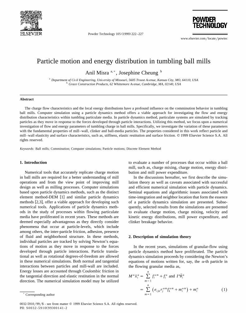
As examples, selected results are presented for tumblingsimulations of a 2-dimensional mill of 2 m diametercontaining five hundred 50 mm balls. This mill representsa filling level of ;38% and critical speed of 30 rpm.Further, in these examples, the friction coefficient, m, forball–ball and ball-mill–wall interactions is selected to be0.4 and 0.6, respectively. The material parameters forball-media were selected as follows: elastic modulus Es150 GPa, ball densitys8 Mgrm3, and restitution coeffi-cient for ball–ball and ball–wall interactions ´s0.4. Theball trajectories, resulting from the tumbling simulations,are plotted in Fig. 1 for four mill revolutions at three millrotation speeds. In the trajectory plots, we select the ballsthat are initially located along the vertical diameter andfollow them during the simulation. To differentiate theselected balls, each ball is assigned a gray-scale, beginning
Fig. 1. Ball trajectories for 4 mill revolutions at 66%, 83%, and 93% critical speed.
( )A. Misra, J. CheungrPowder Technology 105 1999 222–227 225
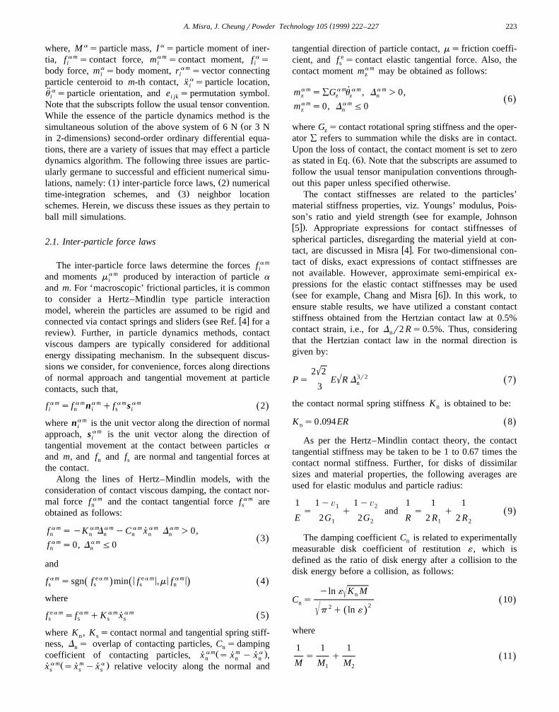
Fig. 2. Radial and tangential velocity distributions.
with a light gray for balls located near the mill center to adark gray for balls near the mill wall. Needless to say athigher mill speeds, the ball media motion is more energeticwith a higher degree of media fluidization. In addition,media mixing increases with mill-speeds as shown by theincreased overlapping of different gray-scaled trajectoriesat higher mill-speed.
The instantaneous radial and tangential velocity distri-butions at the end of three revolutions of the above mill
Ž .rotated at 83% critical speed i.e., 25 rpm are given inFig. 2. As may be expected, the average radial velocity isalmost zero. Nevertheless, balls with non-zero radial veloc-ity exist, which is an indicator of media mixing. Also, it isnoteworthy that a few balls have radial velocities as highas 2–4 mrs. It is surmised that these balls are the onesthat are falling unhindered onto the mill bottom, thereforethey have attained high velocities. These balls may beexpected to contribute most to the clinker comminution.The large spread in tangential velocity is expected as theserepresent those balls that are being carried up by the millwall as well those that are falling down due to gravity.
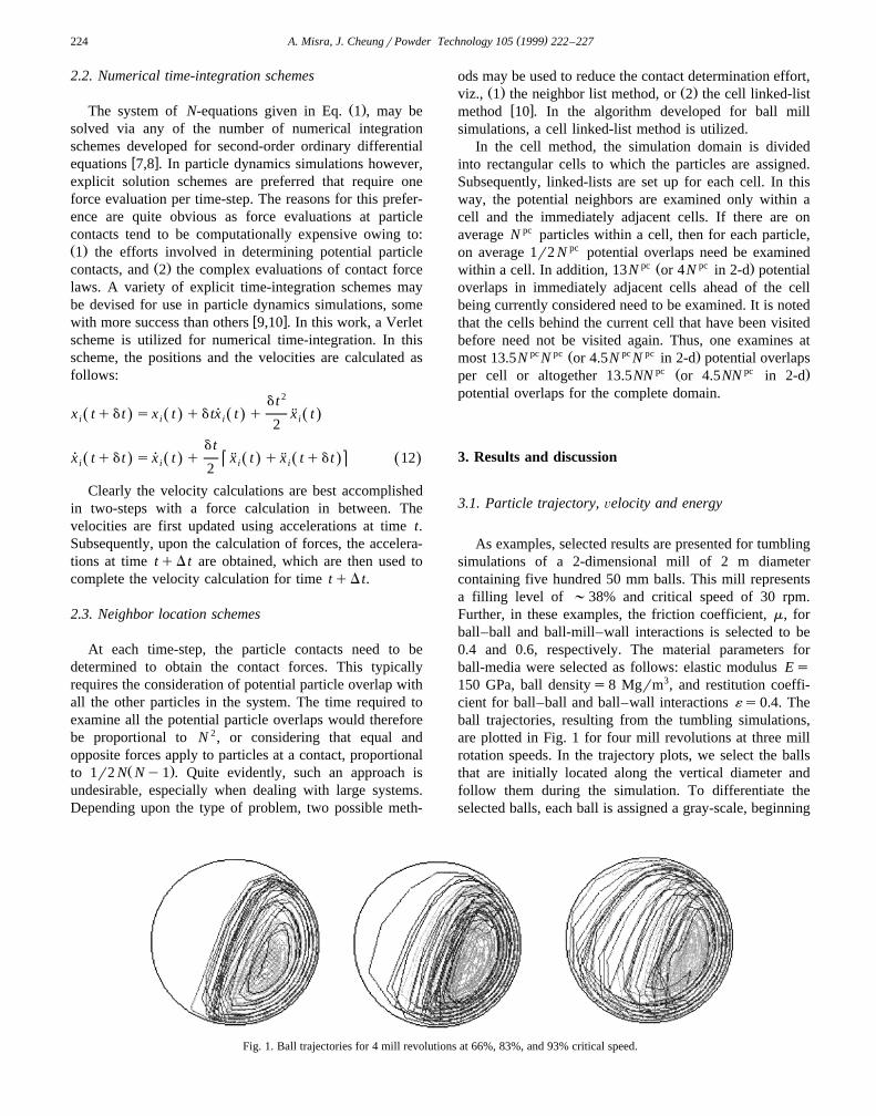
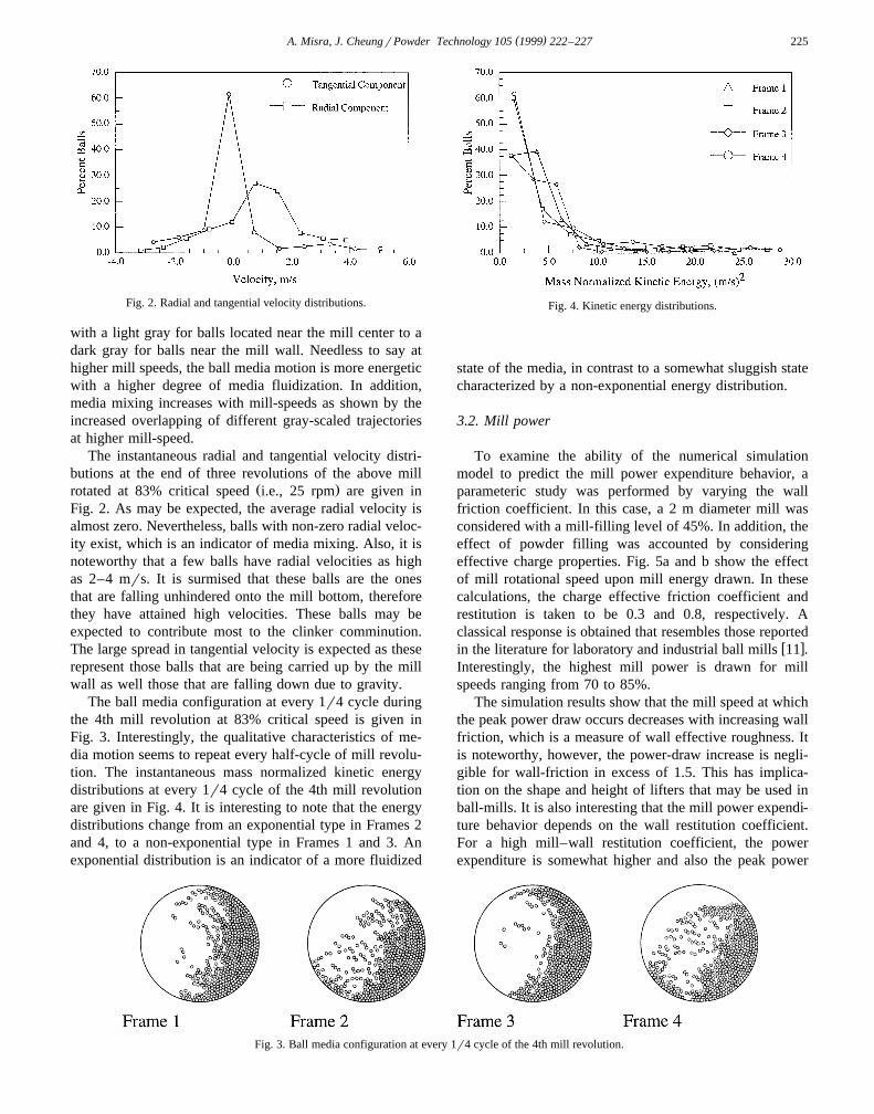
The ball media configuration at every 1r4 cycle duringthe 4th mill revolution at 83% critical speed is given inFig. 3. Interestingly, the qualitative characteristics of me-dia motion seems to repeat every half-cycle of mill revolu-tion. The instantaneous mass normalized kinetic energydistributions at every 1r4 cycle of the 4th mill revolutionare given in Fig. 4. It is interesting to note that the energydistributions change from an exponential type in Frames 2and 4, to a non-exponential type in Frames 1 and 3. Anexponential distribution is an indicator of a more fluidized
Fig. 4. Kinetic energy distributions.
state of the media, in contrast to a somewhat sluggish statecharacterized by a non-exponential energy distribution.
3.2. Mill power
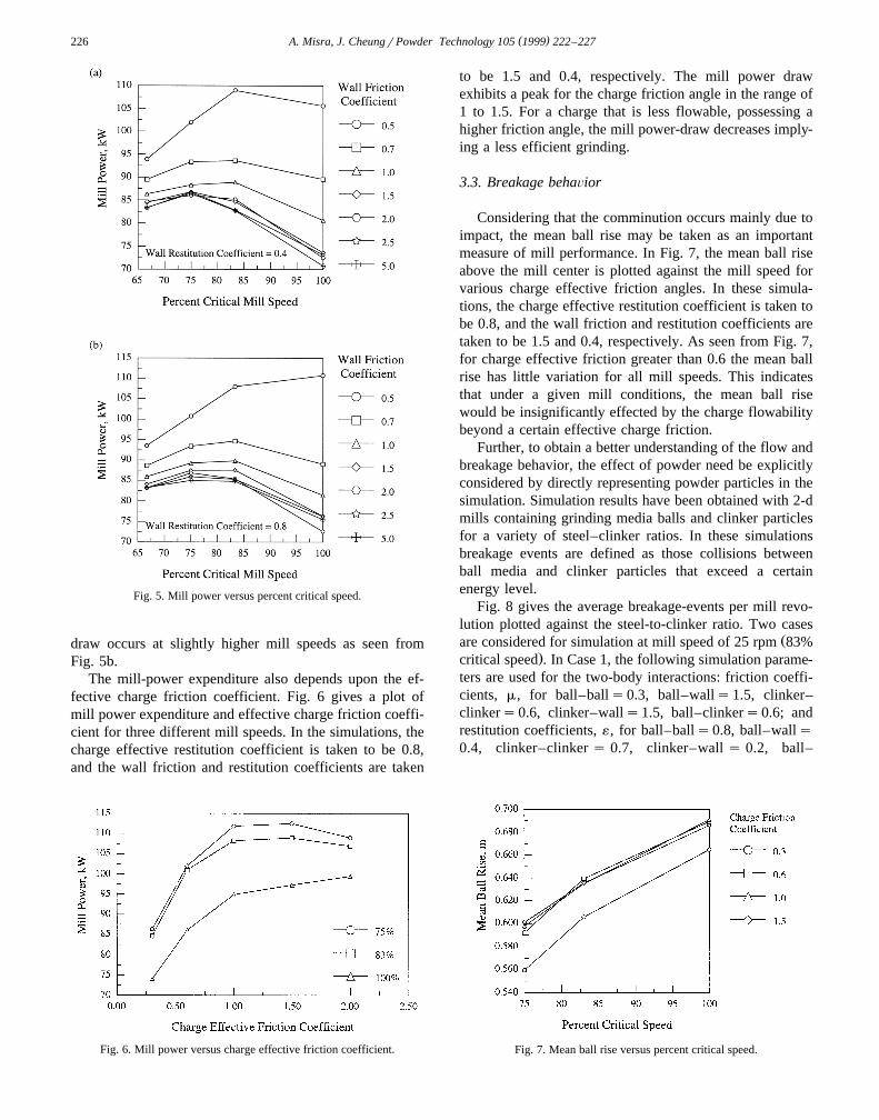
To examine the ability of the numerical simulationmodel to predict the mill power expenditure behavior, aparameteric study was performed by varying the wallfriction coefficient. In this case, a 2 m diameter mill wasconsidered with a mill-filling level of 45%. In addition, theeffect of powder filling was accounted by consideringeffective charge properties. Fig. 5a and b show the effectof mill rotational speed upon mill energy drawn. In thesecalculations, the charge effective friction coefficient andrestitution is taken to be 0.3 and 0.8, respectively. Aclassical response is obtained that resembles those reported
w xin the literature for laboratory and industrial ball mills 11 .Interestingly, the highest mill power is drawn for millspeeds ranging from 70 to 85%.
The simulation results show that the mill speed at whichthe peak power draw occurs decreases with increasing wallfriction, which is a measure of wall effective roughness. Itis noteworthy, however, the power-draw increase is negli-gible for wall-friction in excess of 1.5. This has implica-tion on the shape and height of lifters that may be used inball-mills. It is also interesting that the mill power expendi-ture behavior depends on the wall restitution coefficient.For a high mill–wall restitution coefficient, the powerexpenditure is somewhat higher and also the peak power
Fig. 3. Ball media configuration at every 1r4 cycle of the 4th mill revolution.
( )A. Misra, J. CheungrPowder Technology 105 1999 222–227226
Fig. 5. Mill power versus percent critical speed.
draw occurs at slightly higher mill speeds as seen fromFig. 5b.
The mill-power expenditure also depends upon the ef-fective charge friction coefficient. Fig. 6 gives a plot ofmill power expenditure and effective charge friction coeffi-cient for three different mill speeds. In the simulations, thecharge effective restitution coefficient is taken to be 0.8,and the wall friction and restitution coefficients are taken
Fig. 6. Mill power versus charge effective friction coefficient.
to be 1.5 and 0.4, respectively. The mill power drawexhibits a peak for the charge friction angle in the range of1 to 1.5. For a charge that is less flowable, possessing ahigher friction angle, the mill power-draw decreases imply-ing a less efficient grinding.
3.3. Breakage behaÕior
Considering that the comminution occurs mainly due toimpact, the mean ball rise may be taken as an importantmeasure of mill performance. In Fig. 7, the mean ball riseabove the mill center is plotted against the mill speed forvarious charge effective friction angles. In these simula-tions, the charge effective restitution coefficient is taken tobe 0.8, and the wall friction and restitution coefficients aretaken to be 1.5 and 0.4, respectively. As seen from Fig. 7,for charge effective friction greater than 0.6 the mean ballrise has little variation for all mill speeds. This indicatesthat under a given mill conditions, the mean ball risewould be insignificantly effected by the charge flowabilitybeyond a certain effective charge friction.
Further, to obtain a better understanding of the flow andbreakage behavior, the effect of powder need be explicitlyconsidered by directly representing powder particles in thesimulation. Simulation results have been obtained with 2-dmills containing grinding media balls and clinker particlesfor a variety of steel–clinker ratios. In these simulationsbreakage events are defined as those collisions betweenball media and clinker particles that exceed a certainenergy level.
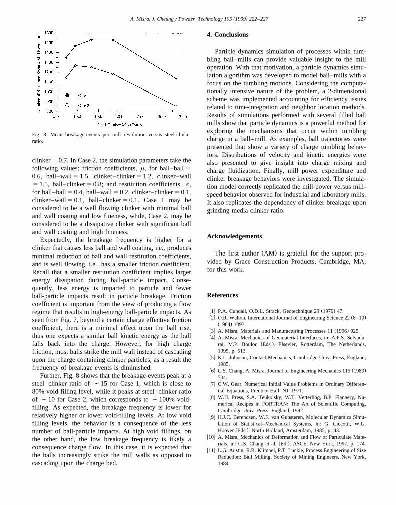
Fig. 8 gives the average breakage-events per mill revo-lution plotted against the steel-to-clinker ratio. Two cases
Žare considered for simulation at mill speed of 25 rpm 83%.critical speed . In Case 1, the following simulation parame-
ters are used for the two-body interactions: friction coeffi-cients, m, for ball–balls0.3, ball–walls1.5, clinker–clinkers0.6, clinker–walls1.5, ball–clinkers0.6; andrestitution coefficients, ´, for ball–balls0.8, ball–walls0.4, clinker–clinker s 0.7, clinker–wall s 0.2, ball–
Fig. 7. Mean ball rise versus percent critical speed.
( )A. Misra, J. CheungrPowder Technology 105 1999 222–227 227
Fig. 8. Mean breakage-events per mill revolution versus steel-clinkerratio.
clinkers0.7. In Case 2, the simulation parameters take thefollowing values: friction coefficients, m, for ball–balls0.6, ball–walls1.5, clinker–clinkers1.2, clinker–walls1.5, ball–clinkers0.8; and restitution coefficients, ´ ,for ball–balls0.4, ball–walls0.2, clinker–clinkers0.1,clinker–walls0.1, ball–clinkers0.1. Case 1 may beconsidered to be a well flowing clinker with minimal balland wall coating and low fineness, while, Case 2, may beconsidered to be a dissipative clinker with significant balland wall coating and high fineness.
Expectedly, the breakage frequency is higher for aclinker that causes less ball and wall coating, i.e., producesminimal reduction of ball and wall restitution coefficients,and is well flowing, i.e., has a smaller friction coefficient.Recall that a smaller restitution coefficient implies largerenergy dissipation during ball-particle impact. Conse-quently, less energy is imparted to particle and fewerball-particle impacts result in particle breakage. Frictioncoefficient is important from the view of producing a flowregime that results in high-energy ball-particle impacts. Asseen from Fig. 7, beyond a certain charge effective frictioncoefficient, there is a minimal effect upon the ball rise,thus one expects a similar ball kinetic energy as the ballfalls back into the charge. However, for high chargefriction, most balls strike the mill wall instead of cascadingupon the charge containing clinker particles, as a result thefrequency of breakage events is diminished.
Further, Fig. 8 shows that the breakage-events peak at asteel–clinker ratio of ;15 for Case 1, which is close to80% void-filling level, while it peaks at steel–clinker ratioof ;10 for Case 2, which corresponds to ;100% void-filling. As expected, the breakage frequency is lower forrelatively higher or lower void-filling levels. At low voidfilling levels, the behavior is a consequence of the lessnumber of ball-particle impacts. At high void fillings, onthe other hand, the low breakage frequency is likely aconsequence charge flow. In this case, it is expected thatthe balls increasingly strike the mill walls as opposed tocascading upon the charge bed.
4. Conclusions
Particle dynamics simulation of processes within tum-bling ball–mills can provide valuable insight to the milloperation. With that motivation, a particle dynamics simu-lation algorithm was developed to model ball–mills with afocus on the tumbling motions. Considering the computa-tionally intensive nature of the problem, a 2-dimensionalscheme was implemented accounting for efficiency issuesrelated to time-integration and neighbor location methods.Results of simulations performed with several filled ballmills show that particle dynamics is a powerful method forexploring the mechanisms that occur within tumblingcharge in a ball–mill. As examples, ball trajectories werepresented that show a variety of charge tumbling behav-iors. Distributions of velocity and kinetic energies werealso presented to give insight into charge mixing andcharge fluidization. Finally, mill power expenditure andclinker breakage behaviors were investigated. The simula-tion model correctly replicated the mill-power versus mill-speed behavior observed for industrial and laboratory mills.It also replicates the dependency of clinker breakage upongrinding media-clinker ratio.
Acknowledgements
Ž .The first author AM is grateful for the support pro-vided by Grace Construction Products, Cambridge, MA,for this work.
References
w x Ž .1 P.A. Cundall, O.D.L. Strack, Geotechnique 29 1979 47.w x Ž .2 O.R. Walton, International Journal of Engineering Science 22 8–10
Ž .1984 1097.w x Ž .3 A. Misra, Materials and Manufacturing Processes 11 1996 925.w x4 A. Misra, Mechanics of Geomaterial Interfaces, in: A.P.S. Selvadu-
Ž .rai, M.P. Boulon Eds. , Elsevier, Rotterdam, The Netherlands,1995, p. 513.
w x5 K.L. Johnson, Contact Mechanics, Cambridge Univ. Press, England,1985.
w x Ž .6 C.S. Chang, A. Misra, Journal of Engineering Mechanics 115 1989704.
w x7 C.W. Gear, Numerical Initial Value Problems in Ordinary Differen-tial Equations, Prentice-Hall, NJ, 1971.
w x8 W.H. Press, S.A. Teukolsky, W.T. Vetterling, B.P. Flannery, Nu-merical Recipes in FORTRAN: The Art of Scientific Computing,Cambridge Univ. Press, England, 1992.
w x9 H.J.C. Berendsen, W.F. van Gunsteren, Molecular Dynamics Simu-lation of Statistical–Mechanical Systems, in: G. Ciccotti, W.G.
Ž .Hoover Eds. , North Holland, Amsterdam, 1985, p. 43.w x10 A. Misra, Mechanics of Deformation and Flow of Particulate Mate-
Ž .rials, in: C.S. Chang et al. Ed. , ASCE, New York, 1997, p. 174.w x11 L.G. Austin, R.R. Klimpel, P.T. Luckie, Process Engineering of Size
Reduction: Ball Milling, Society of Mining Engineers, New York,1984.