Embed Size (px)
Citation preview

Particle Beam DiagnosticsProf. Carsten P. Welsch
Prof. C.P. Welsch – Particle Beam Diagnostics, CAS, November 2014
Further Reading
CAS Beam Diagnostics, Dourdan, France (2008)
DITANET Beam Diagnostics Schools in 2009 and 2011
DITANET Topical Workshops– Transverse Beam Profile Monitoring,
– Longitudinal beam profile monitoring, CI, UK
– Beam Loss Monitoring, DESY, Germany
www.liv.ac.uk/ditanet or CERN indico, search for DITANET
Credits
Many thanks to R. Fiorito, T. Lefèvre, E. Bravin,
A. Jeff, H. Braun, R. Jones, P. Forck and S. Jolly.
Prof. C.P. Welsch – Particle Beam Diagnostics, CAS, November 2014
Overview
Lecture 1 („the basics“)
– Transverse beam profile
– Longitudinal beam profile
– Beam position
– Beam energy
Lecture 2 („advanced topics“)
– Beam emittance
– Beam halo
– Non-invasive beam profile measurements
This school covers wide range of charged particle beams in terms if their time structure, profile, energy and other characteristics. Diagnostics suitable for essentially and particle beam will be presented and specific challenges in a
novel accelerators context highlighted.
Prof. C.P. Welsch – Particle Beam Diagnostics, CAS, November 2014
The ideal diagnostics
Precise information about the beam(Sensitivity, time/spatial resolution, accuracy, DR)
Single shot diagnostics– Avoids problems with reproducibility
– And timing jitter
Non-interceptive– On-line monitoring of the beam
– No risk of damage by the beam itself
– Important for high power beams !
Prof. C.P. Welsch – Particle Beam Diagnostics, CAS, November 2014
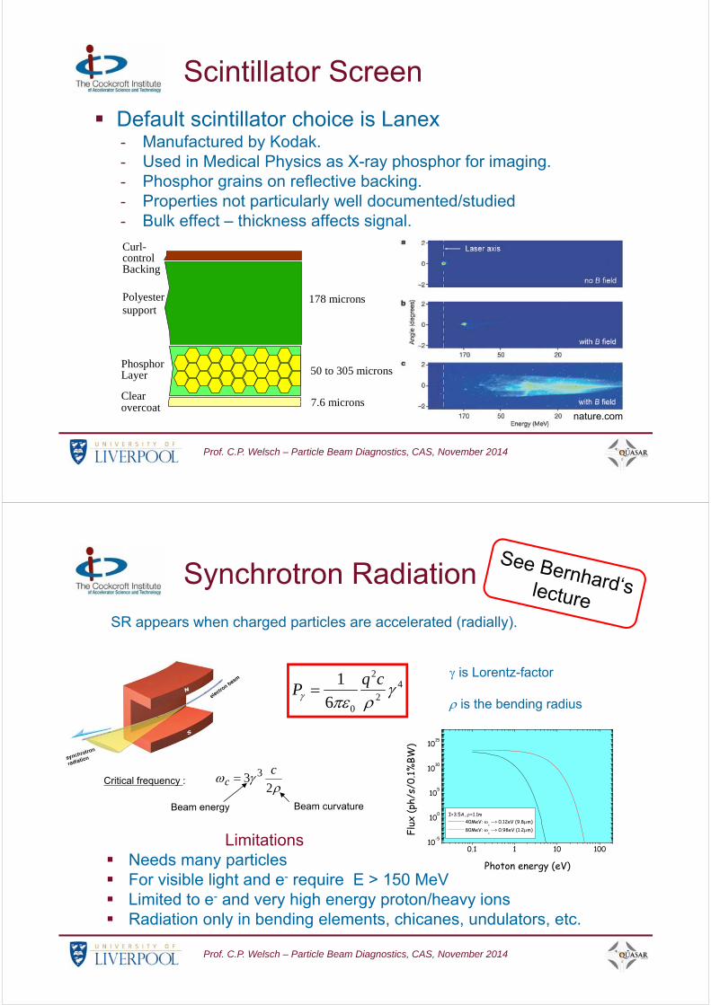
Scintillator Screen
Default scintillator choice is Lanex- Manufactured by Kodak.- Used in Medical Physics as X-ray phosphor for imaging.- Phosphor grains on reflective backing.- Properties not particularly well documented/studied- Bulk effect – thickness affects signal.
Curl-controlBacking
Polyestersupport
PhosphorLayer
Clearovercoat
178 microns
50 to 305 microns
7.6 micronsnature.com
Prof. C.P. Welsch – Particle Beam Diagnostics, CAS, November 2014
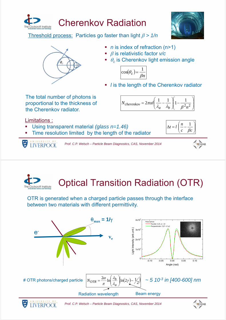
SR appears when charged particles are accelerated (radially).
Critical frequency :
23 3 c
c
Beam curvatureBeam energy
0.1 1 10 10010-5
100
105
1010
1015
I=3.5A, =1.1m 40MeV:
c --> 0.12eV (9.8m)
80MeV: c --> 0.98eV (1.2m)
Flux
(ph/
s/0.
1%BW
)
Photon energy (eV)
42
2
06
1
cqP
is Lorentz-factor
is the bending radius
Synchrotron Radiation
Limitations Needs many particles For visible light and e- require E > 150 MeV Limited to e- and very high energy proton/heavy ions Radiation only in bending elements, chicanes, undulators, etc.
Prof. C.P. Welsch – Particle Beam Diagnostics, CAS, November 2014
Threshold process: Particles go faster than light > 1/n
nc
1cos
n is index of refraction (n>1) is relativistic factor v/c c is Cherenkov light emission angle
l is the length of the Cherenkov radiator
The total number of photons is proportional to the thickness of the Cherenkov radiator.
221
111
2n
lNba
cherenkov
cc
nlt
1
Cherenkov Radiation
Limitations : Using transparent material (glass n=1.46) Time resolution limited by the length of the radiator
Prof. C.P. Welsch – Particle Beam Diagnostics, CAS, November 2014
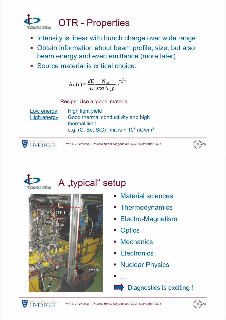
OTR is generated when a charged particle passes through the interface between two materials with different permittivity.
-0.10 -0.05 0.00 0.05 0.100
1x10⁴
2x10⁴
3x10⁴
4x10⁴
Polarization Parallel I (, ) Perpendicular I ( = 0, )
Ligh
t in
tens
ity (
arb
.uni
t.)
Angle (rad)
Radiation wavelength Beam energy
# OTR photons/charged particle ~ 5 10-3 in [400-600] nm 212lnln
2
a
bOTRN
Optical Transition Radiation (OTR)
max = 1/
ve
e-
Prof. C.P. Welsch – Particle Beam Diagnostics, CAS, November 2014
OTR - Properties
Intensity is linear with bunch charge over wide range
Obtain information about beam profile, size, but also beam energy and even emittance (more later)
Source material is critical choice:
Recipe: Use a ‘good’ material
Low energy: High light yieldHigh energy: Good thermal conductivity and high
thermal limit e.g. (C, Be, SiC) limit is ~ 106 nC/cm2
2
2
222
)(
r
p
tot ec
N
dx
dErT
Prof. C.P. Welsch – Particle Beam Diagnostics, CAS, November 2014
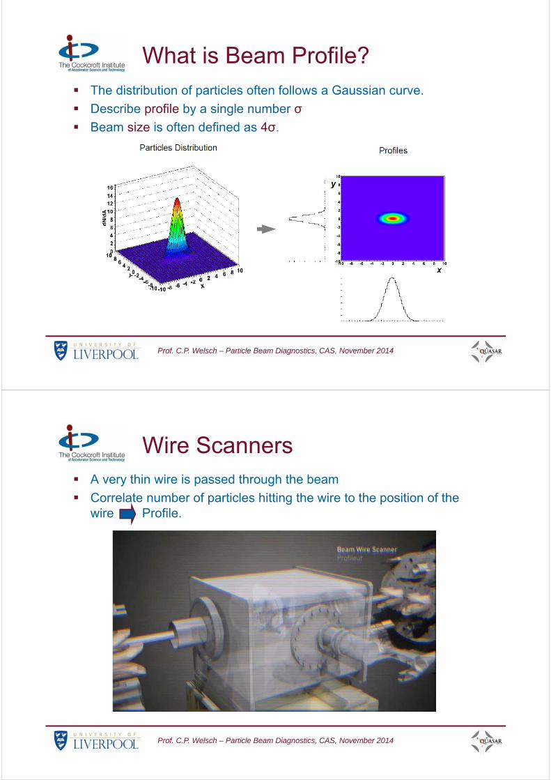
A „typical“ setup Material sciences
Thermodynamics
Electro-Magnetism
Optics
Mechanics
Electronics
Nuclear Physics
…
Diagnostics is exciting !
Camera
OTR Light

Prof. C.P. Welsch – Particle Beam Diagnostics, CAS, November 2014
ODR is generated when a charged particle passes near the edge of a dielectric and the distance to the target h satisfies the condition :
Radiation wavelength
Beam energy
2
h
Optical Diffraction Radiation (ODR)
Limitation
Limited # of photons in the visible for low energy particles (E < 1 GeV) and decent impact parameters (100 m).
Prof. C.P. Welsch – Particle Beam Diagnostics, CAS, November 2014
What is Beam Profile?
The beam is made up of many particles which move independently.
However the distribution generally stays the same.
The distribution of particles plotted against x or y is the (horizontal or vertical) profile.
Some instruments measure cross-section, others the profiles.
Prof. C.P. Welsch – Particle Beam Diagnostics, CAS, November 2014
What is Beam Profile? The distribution of particles often follows a Gaussian curve.
Describe profile by a single number σ
Beam size is often defined as 4σ.
Prof. C.P. Welsch – Particle Beam Diagnostics, CAS, November 2014
Wire Scanners A very thin wire is passed through the beam
Correlate number of particles hitting the wire to the position of the wire Profile.
Prof. C.P. Welsch – Particle Beam Diagnostics, CAS, November 2014
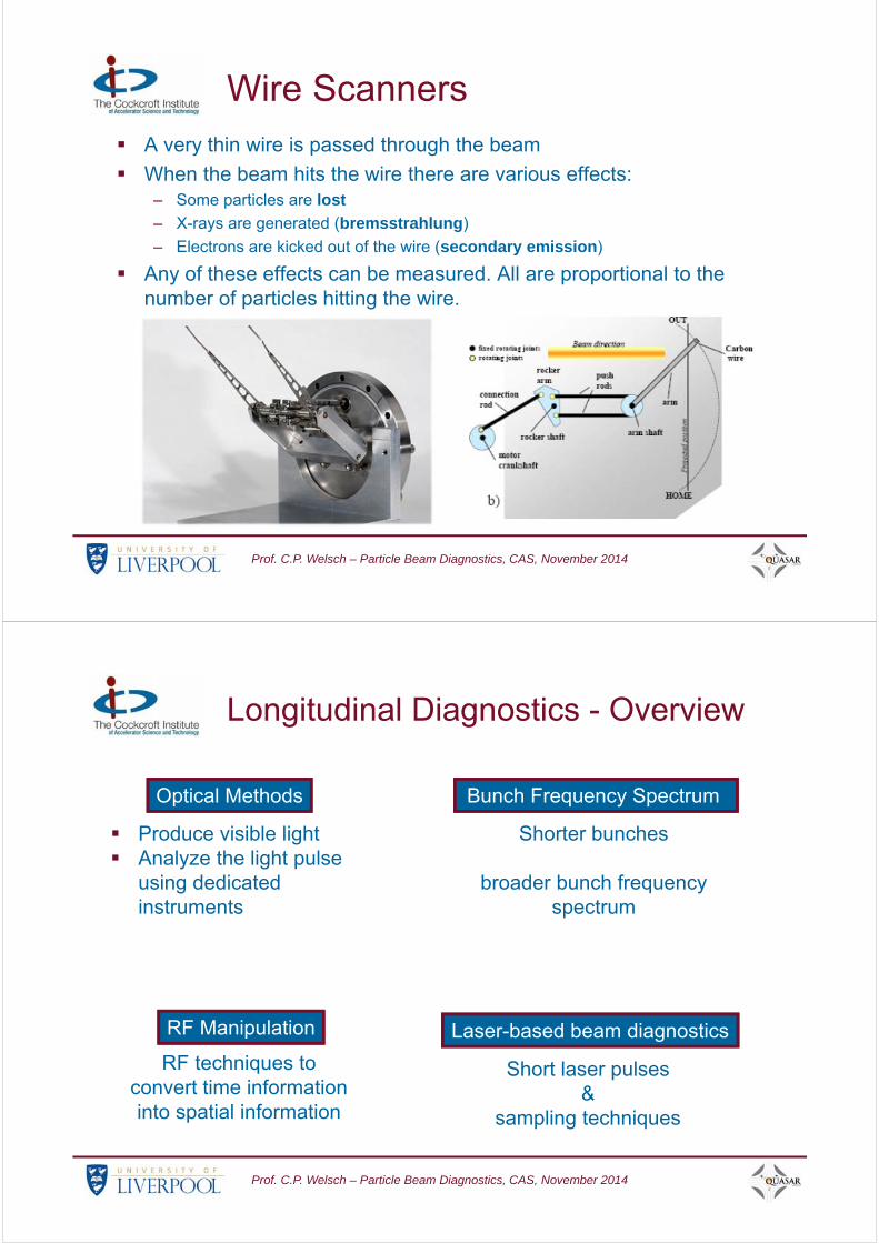
Wire Scanners A very thin wire is passed through the beam
When the beam hits the wire there are various effects:– Some particles are lost
– X-rays are generated (bremsstrahlung)
– Electrons are kicked out of the wire (secondary emission)
Any of these effects can be measured. All are proportional to the number of particles hitting the wire.
Prof. C.P. Welsch – Particle Beam Diagnostics, CAS, November 2014
Optical Methods
Produce visible light Analyze the light pulse
using dedicated instruments
RF Manipulation
RF techniques to convert time information into spatial information
Bunch Frequency Spectrum
Shorter bunches
broader bunch frequency spectrum
Laser-based beam diagnostics
Short laser pulses &
sampling techniques
Longitudinal Diagnostics - Overview
Prof. C.P. Welsch – Particle Beam Diagnostics, CAS, November 2014
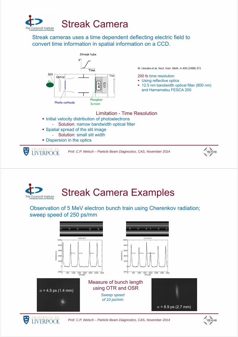
M. Uesaka et al, Nucl. Instr. Meth. A 406 (1998) 371
200 fs time resolution Using reflective optics 12.5 nm bandwidth optical filter (800 nm)
and Hamamatsu FESCA 200
Streak cameras uses a time dependent deflecting electric field to convert time information in spatial information on a CCD.
Streak Camera
Limitation - Time Resolution Initial velocity distribution of photoelectrons
- Solution: narrow bandwidth optical filter Spatial spread of the slit image
- Solution: small slit width Dispersion in the optics
Prof. C.P. Welsch – Particle Beam Diagnostics, CAS, November 2014
Observation of 5 MeV electron bunch train using Cherenkov radiation; sweep speed of 250 ps/mm
= 8.9 ps (2.7 mm)
= 4.5 ps (1.4 mm)Sweep speed of 10 ps/mm
Measure of bunch length using OTR and OSR
Streak Camera Examples
Prof. C.P. Welsch – Particle Beam Diagnostics, CAS, November 2014
eV
z
eV0
ee
zz
yy
c
yy
66 00°°p
2
0
022 cossin2
0
E
eVpczyy
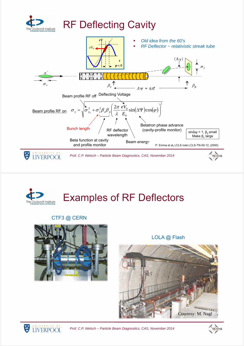
RF deflectorwavelength
Betatron phase advance(cavity-profile monitor)
Beta function at cavityand profile monitor
Beam energy
Deflecting Voltage
Bunch lengthsin∆ψ = 1, βp small
Make βc large
Beam profile RF on
Beam profile RF off
P. Emma et al, LCLS note LCLS-TN-00-12, (2000)
Old idea from the 60’s RF Deflector ~ relativistic streak tube
RF Deflecting Cavity
Prof. C.P. Welsch – Particle Beam Diagnostics, CAS, November 2014
CTF3 @ CERN
LOLA @ Flash
Courtesy: M. Nagl
Examples of RF Deflectors

Prof. C.P. Welsch – Particle Beam Diagnostics, CAS, November 2014
Electron energy is modulated by the zero-phasing RF accelerating field. Bunch distributionis then deduced from the energy dispersion measured downstream.
t E x
RF Accelerating Structures
Prof. C.P. Welsch – Particle Beam Diagnostics, CAS, November 2014
D. X. Wang et al, Physical Review E57 (1998) 2283
84 fs, 45 MeV beam but low charge beam
RF off RF on
CEBAF injector, Newport News
1st SRF module
2nd SRF moduleused for zero-phasing
45MeV spectrometer dipole
Beam profile
monitor
RF Accelerating Structures
Limitations RF non-linearities Beam loading and wakefields for high charge beam

Prof. C.P. Welsch – Particle Beam Diagnostics, CAS, November 2014
e-
hsc=2 h
scsc
h
Thomson/Compton scattering
e- beam
High power laser
Scanningsystem
Detection system based on The measurement of the
scattered photons The measurement of degraded
electrons102 103 104 105
0.3
0.4
0.5
0.6
0.7
0.8
0.9
1.0
c /
0
Electron beam energy (MeV)
0 = 6.65 10-24 cm2
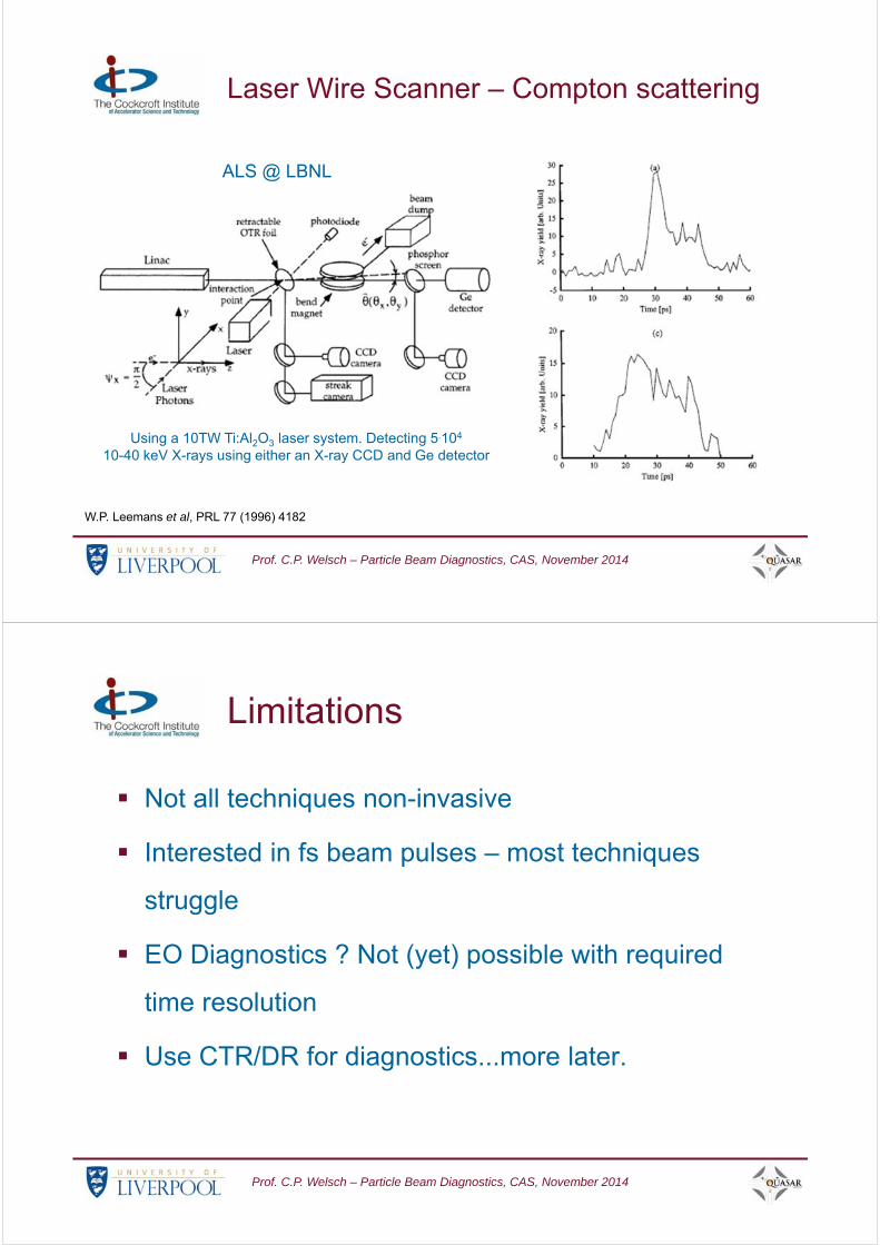
Laser Wire Scanner – Compton scattering
Prof. C.P. Welsch – Particle Beam Diagnostics, CAS, November 2014
1 10 100 1000
0.1
1
1010 GeV electron beam
500 GeV electron beam
1.5 TeV electron beam
Cro
ss s
ectio
n d
/dE
(ar
b. u
nit.)
- rays energy (GeV)
0 300 600 900 1200 1500
10-6
10-5
10-4
10-3
10-2
Cri
tical
ang
le (
rad)
Electron energy (GeV)
Energy spectrum of scattered photons
Using a 266nm wavelength laser
Emission angle of the scattered photons
2
021cm
h
c
The photons steal most of the electron energy (electron recoil becomes extremely important)
The photons are emitted within a very small angle (a few mrad) in the forward direction Measurement of degraded electrons only feasible at high energies
At very high energy
Laser Wire Scanner – Compton scattering
Prof. C.P. Welsch – Particle Beam Diagnostics, CAS, November 2014
Using a 10TW Ti:Al2O3 laser system. Detecting 5.104
10-40 keV X-rays using either an X-ray CCD and Ge detector
W.P. Leemans et al, PRL 77 (1996) 4182
ALS @ LBNL
Laser Wire Scanner – Compton scattering
Prof. C.P. Welsch – Particle Beam Diagnostics, CAS, November 2014
Limitations
Not all techniques non-invasive
Interested in fs beam pulses – most techniques
struggle
EO Diagnostics ? Not (yet) possible with required
time resolution
Use CTR/DR for diagnostics...more later.

Prof. C.P. Welsch – Particle Beam Diagnostics, CAS, November 2014
Beam Position
Idea: Benefit from charge induced by the beam
-- - - -+
+ + ++- +++- -+ -+
+--+
-- ++-+ -
- -- - - -+
+ + ++- +++- -+ -+
+--+
-- ++-+ -
- -- - - -+
+ ++- +
++- -+ -++--+
-- ++-
Prof. C.P. Welsch – Particle Beam Diagnostics, CAS, November 2014
-- - - -+
+ + ++- +++- -+ -+
+--+
-- ++-+ -
-- - - - -+ +
++- ++ +- -+ -+ +- -+ -+ -
- -- - - -+
+ ++- +
++- -+ -++--+
-- ++-+-
V
- - - - - - -
Beam Position
Prof. C.P. Welsch – Particle Beam Diagnostics, CAS, November 2014
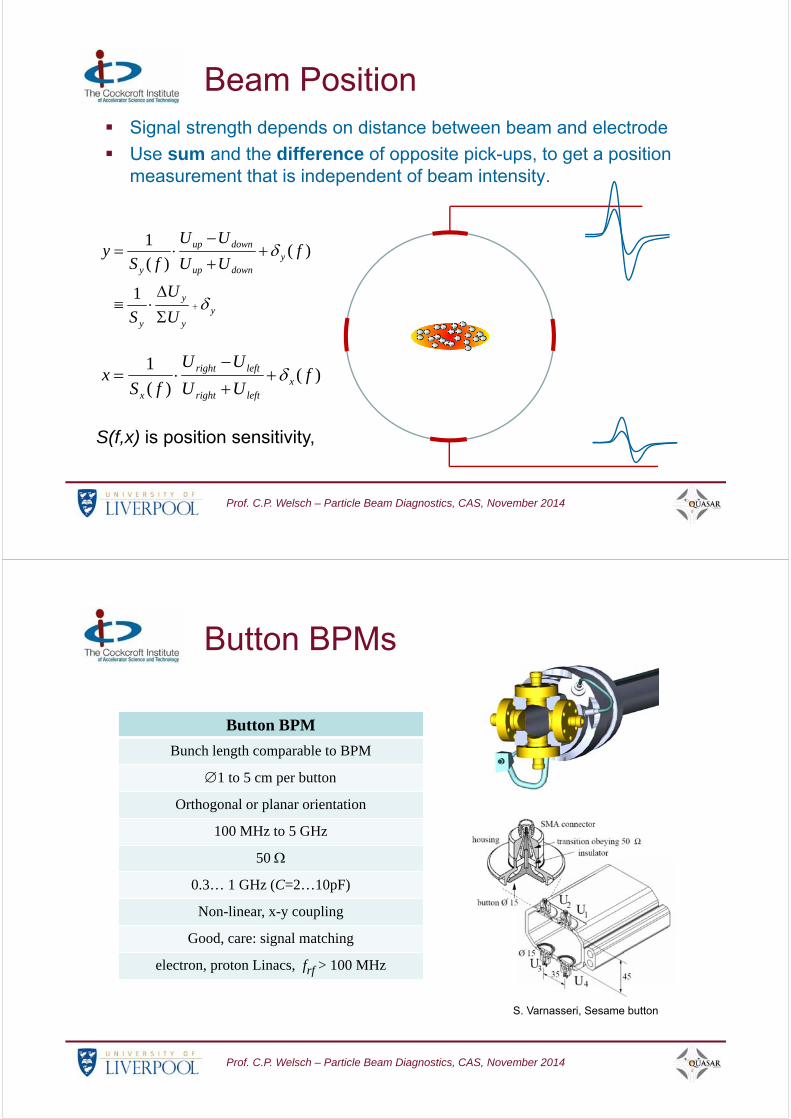
Beam Position Signal strength depends on distance between beam and electrode
Use sum and the difference of opposite pick-ups, to get a position measurement that is independent of beam intensity.
+
+ ++ ++
+ ++
+ +++
+++
++
+++ +
+
S(f,x) is position sensitivity,
yy
y
y
ydownup
downup
y
U
U
S
fUU
UU
fSy
1
)()(
1
)()(
1f
UU
UU
fSx x
leftright
leftright
x
Prof. C.P. Welsch – Particle Beam Diagnostics, CAS, November 2014
Button BPMs
Button BPM
Bunch length comparable to BPM
1 to 5 cm per button
Orthogonal or planar orientation
100 MHz to 5 GHz
50
0.3… 1 GHz (C=2…10pF)
Non-linear, x-y coupling
Good, care: signal matching
electron, proton Linacs, frf > 100 MHz
S. Varnasseri, Sesame button

Prof. C.P. Welsch – Particle Beam Diagnostics, CAS, November 2014
Button BPMs
Currently not required for PWA as no long beam transport done;
Real multi-stage acceleration would require similar (established) monitors;
DLAs: Future designs will need to include ‚whole‘ accelerator on a chip, including:
– Quadrupole and higher order fields
– Instrumentations, such as BPMs and ICTs
Prof. C.P. Welsch – Particle Beam Diagnostics, CAS, November 2014
Beam Energy Measurement
Pass the beam through a strong
bending magnet;
Particles with higher energy are
bent less and vice versa;
A segmented detector is often
used to measure the ‘spread’
beam;
Destructive measurement.
M. Olvegaard, et al., PRST-AB 16, 022802 (2013).
Prof. C.P. Welsch – Particle Beam Diagnostics, CAS, November 2014
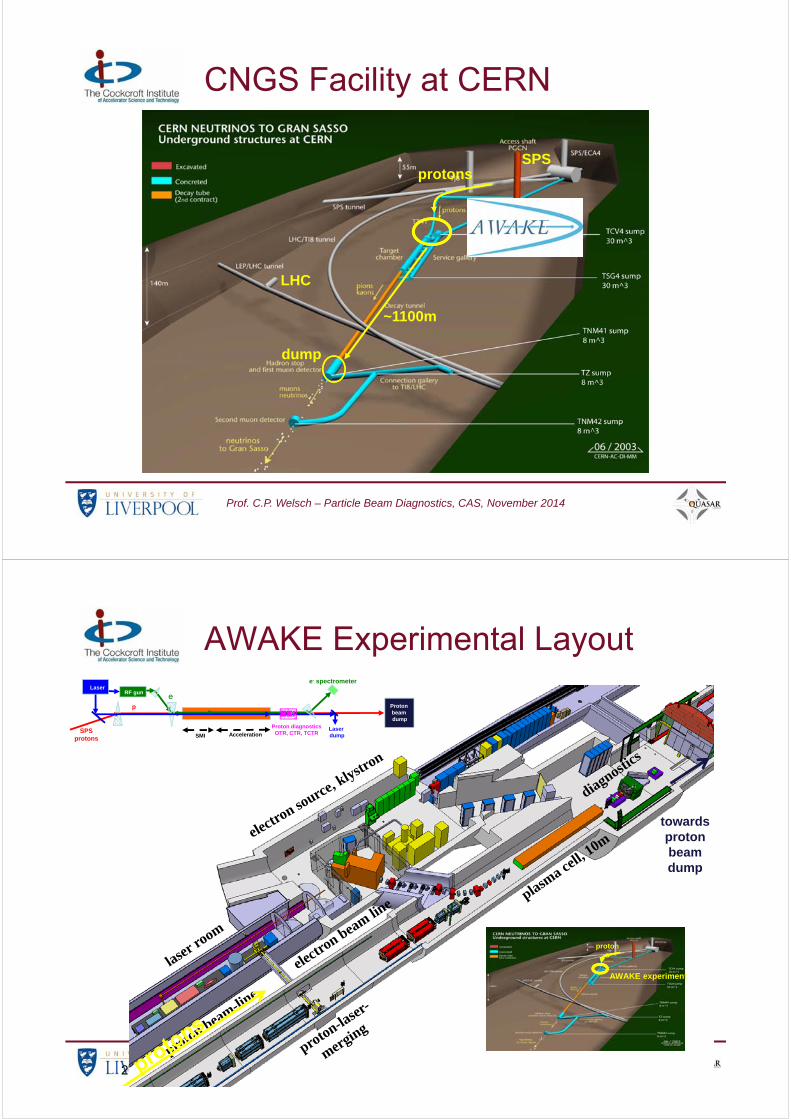
CNGS Facility at CERN
dump
~1100m
SPS
LHC
protons
Prof. C.P. Welsch – Particle Beam Diagnostics, CAS, November 2014
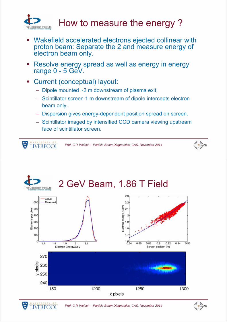
AWAKE Experimental Layout
26/11/2014 Simon Jolly, UCL 34
plasma ce
ll, 10m
diagnostics
electron so
urce, klystron
electr
on beam line
laser ro
om
proton beam-line
proton-laser
-
merging
AWAKE experiment
protons
Laser dump
e- spectrometer
e-
SPSprotons SMI Acceleration
Proton beam dump
RF gunLaser
Proton diagnosticsOTR, CTR, TCTR
p
towards proton beam dump
Prof. C.P. Welsch – Particle Beam Diagnostics, CAS, November 2014
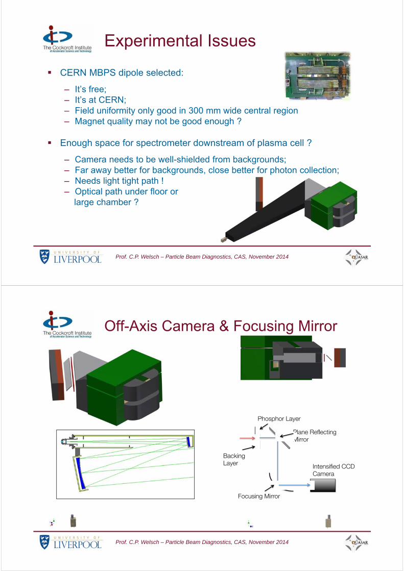
How to measure the energy ?
Wakefield accelerated electrons ejected collinear with proton beam: Separate the 2 and measure energy of electron beam only.
Resolve energy spread as well as energy in energy range 0 - 5 GeV.
Current (conceptual) layout:– Dipole mounted ~2 m downstream of plasma exit;
– Scintillator screen 1 m downstream of dipole intercepts electron beam only.
– Dispersion gives energy-dependent position spread on screen.
– Scintillator imaged by intensified CCD camera viewing upstream face of scintillator screen.
Prof. C.P. Welsch – Particle Beam Diagnostics, CAS, November 2014
2 GeV Beam, 1.86 T Field
Prof. C.P. Welsch – Particle Beam Diagnostics, CAS, November 2014
Experimental Issues
CERN MBPS dipole selected:
– It’s free;– It’s at CERN;– Field uniformity only good in 300 mm wide central region– Magnet quality may not be good enough ?
Enough space for spectrometer downstream of plasma cell ?
– Camera needs to be well-shielded from backgrounds;– Far away better for backgrounds, close better for photon collection;– Needs light tight path !– Optical path under floor or
large chamber ?
Prof. C.P. Welsch – Particle Beam Diagnostics, CAS, November 2014
Off-Axis Camera & Focusing Mirror
Prof. C.P. Welsch – Particle Beam Diagnostics, CAS, November 2014
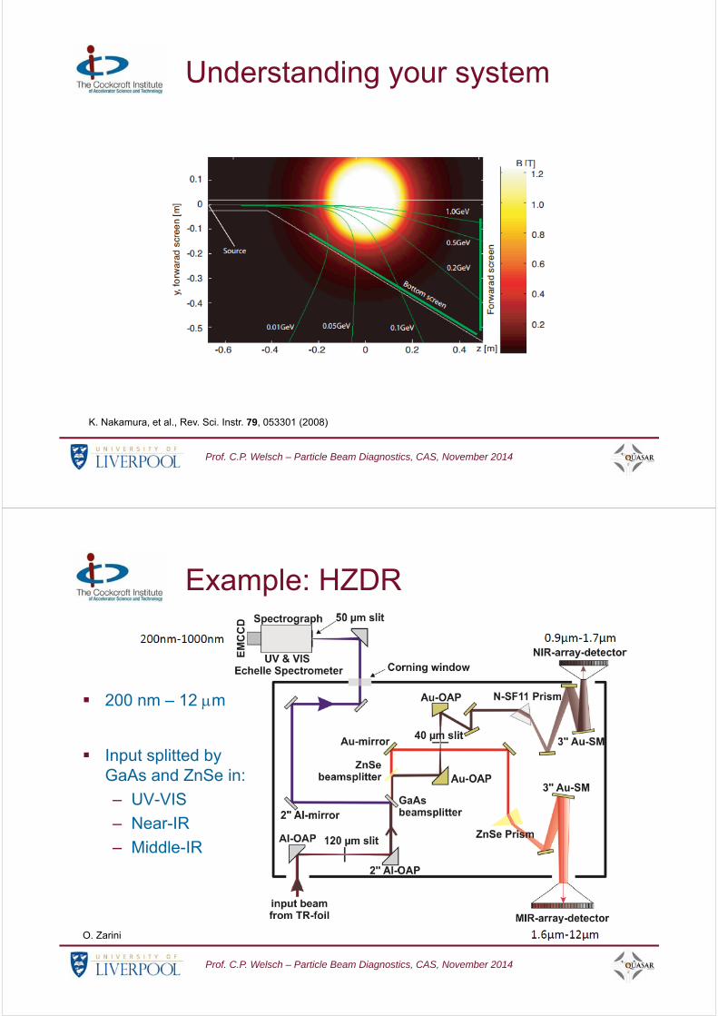
Understanding your system
K. Nakamura, et al., Rev. Sci. Instr. 79, 053301 (2008)
Prof. C.P. Welsch – Particle Beam Diagnostics, CAS, November 2014
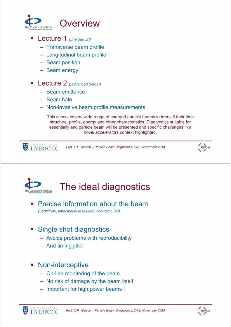
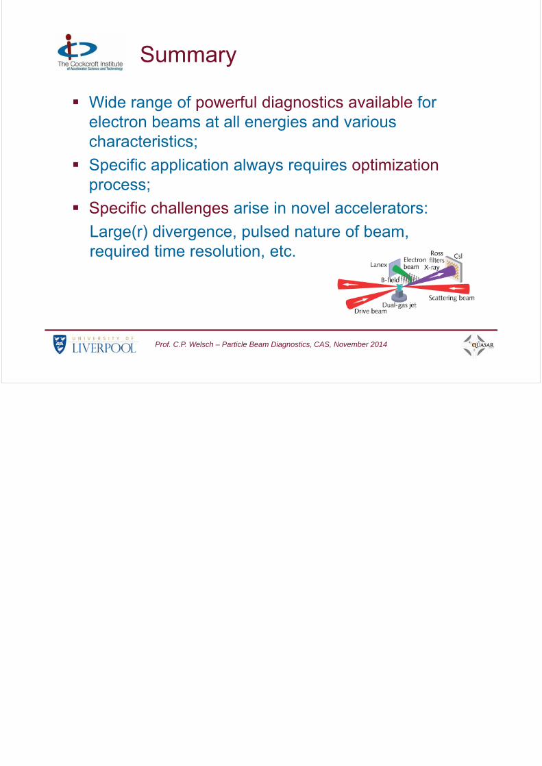
Example: HZDR
O. Zarini
200 nm – 12 m
Input splitted by GaAs and ZnSe in:
– UV-VIS
– Near-IR
– Middle-IR

Prof. C.P. Welsch – Particle Beam Diagnostics, CAS, November 2014
Photo of setup
O. Zarini
Prof. C.P. Welsch – Particle Beam Diagnostics, CAS, November 2014
Callibration Absolute, polarization-dependent callibration is a challenge !
O. Zarini
Prof. C.P. Welsch – Particle Beam Diagnostics, CAS, November 2014
Summary
Wide range of powerful diagnostics available for electron beams at all energies and various characteristics;
Specific application always requires optimization process;
Specific challenges arise in novel accelerators:
Large(r) divergence, pulsed nature of beam, required time resolution, etc.