Embed Size (px)
Citation preview

THE STATE EDUCATION DEPA RT M E N TTHE UNIVERSITY OF THE STATE OF NEW YORK
PART II.9
Bill and Ted’s Eggsellent Adventure............2
NOTE: This document is a work in progress. PartsII and III, in particular, are in need of furtherdevelopment, and we invite the submission ofadditional learning experiences and local perfor-mance tasks for these sections. Inquiries regardingsubmission of materials should be directed to: TheMathematics, Science, and Technology ResourceGuide, Room 681 EBA, New York State EducationDepartment, Albany, NY 12234 (tel. 518-474-5922).
http://www.nysed.gov
&
2 Mathematics, Science, and Technology
▲ investigation/technologicalinvention
▲ creative solutions
▲ work schedules/plans
▲ perform test
▲ prepare multimedia
▲ model solutions
▲ thorough investigation
▲ creative solutions
▲ work schedules/plans
▲ devise test solutions
▲ use equipment correctly
▲ CADD
▲ selecting systems
▲ mathematical models
▲ predictions
▲ design solutions
▲ work effectively
▲ gather/process information
▲ generate/analyze ideas
▲ observe common themes
▲ realize results
▲ present results
C O M M E N C E M E N T
MST
1MST
2MST
5
MST
7
MST
6
Barry E. Borakove
Syosset Central School District
Syosset High School
Syosset, NY 11791
(516) 364-5735
b o r a k o v e @ i x . n e t c o m . c o m
Grades 11&12
Bill and Ted’ssellent
Adventure
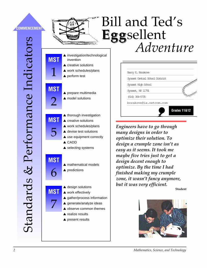
Engineers have to go throughmany designs in order tooptimize their solution. Todesign a crumple zone isn’t aseasy as it seems. It took memaybe five tries just to get adesign decent enough tooptimize. By the time I hadfinished making my crumplezone, it wasn’t fancy anymore,but it was very efficient.
Student

Learning Experiences 3
Introduction to the Design ActivityIn this problem solving and design activity you will use elements of physics, mathematics, andtechnology to design safety systems that will protect the occupants of a vehicle. The vehicle willbe a standard dynamics cart (pur-chased from Frey Scientific). Theoccupants will be two eggs (Billand Ted). The vehicles will betested by sending them down aramp and allowing them to slaminto a concrete block at the bot-tom.
Each team of students will designthe following systems: a restraintsystem, a crumple zone system,an ergonomics system, and a carbody system. The design solu-tions will be modeled and tested.This activity will utilize theenergy model to determinewhether or not the safety systemsdesigned (restraint and crumplezone) will allow the occupants tosurvive a crash test.
When each vehicle is placed on the top of the ramp, it will have a certain amount of stored, orpotential energy (PE) that is a function of the mass of the vehicle (m), the height of the ramp (h)and the acceleration due to gravity (g). This can be expressed as:
PE = mgh
PE is the potential energy in joules;m is the mass in kilograms;h is the height in meters;g is the acceleration due to gravity (a constant 9.8 meters/second2).
Energy is defined as the ability to do work, or the ability to put an object into motion. Work isdefined as the amount of force exerted on an object to move it a specified distance. Work andenergy are both measured in foot-pounds in US units, and in newton-meters in SI (International)units. The joule is an SI unit that is equivalent to one newton-meter. Joules will be used in allcalculations of work and energy in this activity.
The PE of the vehicle can also be referred to as its GPE, or gravitational potential energy. Thevehicle will have a certain number of joules of PE at the top of the ramp. The energy in motion,or kinetic energy (KE) at the top of the ramp will be zero, until the vehicle is released. The carwill accelerate as it travels down the ramp. The increase in the velocity of the car will relate toan increased KE, and a decreased PE. At the bottom of the ramp, the velocity of the vehicle willbe maximum, as will its kinetic energy. The potential energy at the bottom will be zero, indicat-ing that all of the PE has been converted into KE.

4 Mathematics, Science, and Technology
The kinetic energy can be expressed as:
KE = 1/2 mv2
KE is the kinetic energy in joules;m is the mass in kilograms;v is the velocity on meters per second.
This is of course theoretical; all of the potential energy will be not converted into kinetic energyof the vehicle (1/2 mv2) at the bottom of the ramp. Energy will be lost due to friction (betweenthe road surface and the wheels, and between the axles and wheels). Rotational losses will alsobe a factor (the energy used to turn the wheels) in the final velocity at the bottom of the ramp.These frictional and rotational losses can be significant, and must therefore be considered.
Another important consideration is the angle of the ramp. Although the acceleration due togravity is a constant (9.8 m/s2), the angle of the ramp will control the actual acceleration of thevehicle. The vehicle acceleration will be higher as the ramp is made steeper. We can relate thisto the “thrill” of accelerating down a steep section on a roller coaster. The illustration belowshows three ramps at different angles; the height is held constant for each ramp. The ramp at30˚ will accelerate the vehicle the least, and the 60˚ ramp will accelerate the vehicle the most.
If the same vehicle was placed at the top of all three ramps, it would have the same amount ofpotential energy (mgh) which would be converted into kinetic energy as it travels down theramp (including losses). The actual distance traveled along the ramp will differ for each angle;as the ramp steepens, the distance the vehicle travels becomes less. Using the relationships forwork and force, it can be shown that when the vehicle travels a shorter distance (on the 60°ramp), the force of the vehicle upon impact will be higher than it would be on the 30° or 45°ramp. This is evidenced by the greater magnitude of impacts that occur at steeper angles. Theacceleration of the vehicle varies proportionally as the angle of the ramp is changed.
The actual acceleration of the vehicle is proportional to the sine of the angle of the ramp. Theacceleration of the vehicle down the ramp equals the product of the acceleration due to gravityand the sine of the angle:
a = g sinØ
The g sinØ values for each of the three angles above is:
30˚ ramp: 9.8 (.500) = 4.90 m/s2
45˚ ramp: 9.8 (.707) = 6.93 m/s2
60˚ ramp: 9.8 (.866) = 8.49 m/s2
The above example illustrates the significant differences in acceleration that occur as the angle ofthe ramp is varied. These differences in acceleration will translate into proportionally differentforces at impact.

Learning Experiences 5
Inquiry, Analysis and DesignSince the energy model is used in this case study, an analysis of the forces exerted on either thevehicle or the occupants is unnecessary. Resolving the forces (using vectors) requires a muchmore involved analysis. Since the acceleration due to gravity is a constant (9.8 m/s2), tests willbe performed by determining the amount of PE (mgh) each safety system can absorb.
Asuggested apparatus to test the restraint and crumple zone safety systems is described below.The apparatus consists of guides fabricated from 1” PVC pipe, sleeves fabricated from 1 1/4”PVC pipe, a wooden base (5/4x6) and platen (2x6), and a variety of pipe flanges, elbows, andcouplings. The PVC guides are 1-meter long, and spaced approximately 0.5 meters apart. Thespecimen is tested by allowing the platen to drop a specified distance. With the weight of theplaten known, the distance that the platen falls (including the compressed portion of the speci-men) can be used to calculate the potential energy (mgh) absorbed by the specimen. Weightscan be added to the platen to increase the mgh without increasing the height of the apparatus.Tests on each of the safety systems can be analyzed, and the results used to optimize the designsolution.
Eleven members of each design team are expected to actively participate in all of the facets ofthis design and problem solving activity. Although all responsibilities will be shared, each teammember will be placed in charge of a specific subsystem. The Chief Engineer for each subsystemwill be held accountable for the operation and final success of that subsystem.
Subsystem Chief Engineers:■ Restraint Subsystem Chief Engineer: Responsible for “occupants” being held in a
safe/secure position during and after the collision.
■ Crumple Zone Chief Engineer: Responsible for the modeling of the subsystem to insure thatthe design is adequate for the predictable forces and energy transfers at impact.
■ Car Body Design Chief Engineer: Responsible for the design and construction of a realisticlooking car body.
■ Ergonomics Chief Engineer: Responsible for the human factors considerations whichinclude: entry/exit, visibility, and space considerations.
Design teams will determine the forces and energy transfers for their vehicle. They will thendetermine the resulting energy that will be absorbed by their safety systems.
Assessment of Work by Design Teams• Portfolio documenting and describing the design: Research, investigations, report, drawings
• Optimization of design solutions
• Eggonomics of the design
• Realistic component of the car body design
• Presentation/justification of design to class
• Survival of the occupants (Bill and Ted)
• Student Journal/Log Book
• Class participation.
Each Design Team must submit a portfolio which documents their work on this case study.The portfolio must contain each of the following materials:

6 Mathematics, Science, and Technology
Restraint Subsystem • Sketches of all preliminary designs
• Materials chosen and rejected (analysis)
• Test results (mgh) for each trial
• Reasons for failure: observations, causes/effects
• Methods of optimization and results
• Final optimized solution: drawings/description.
Crumple Zone Subsystem • Sketches of all preliminary designs
• Materials chosen and rejected (analysis)
• Test results (mgh, mg h) for each trial as a function of height and/or angle
• Reasons for failure: observations, causes/effects
• Methods of optimization and results
• Final optimized solution: drawings/description.
Car Body Design Subsystem • Sketches of all preliminary designs
• Materials chosen and rejected (analysis)
• Design goals stated: appearance, aerodynamics, ergonomics, weight, and crash-worthiness.
Ergonomics Subsystem • Measurements and investigations on human factors engineering
• Methods used to apply ergonomics to final design
• Evidence of ergonomics in car body design.
Restraint Subsystem Book
Crumple Zone Chief Engineer, AndyRestraint Subsystem Chief Engineer, PatCar Body Chief Engineer, EricErgonomics Chief Engineer, Eric

Learning Experiences 7
Crumble Zone

8 Mathematics, Science, and Technology
Crumble Zone

Learning Experiences 9
Crumble Zone

10 Mathematics, Science, and Technology
Crumble Zone

Learning Experiences 11
Crumble Zone

12 Mathematics, Science, and Technology
Crumble Zone

Learning Experiences 13
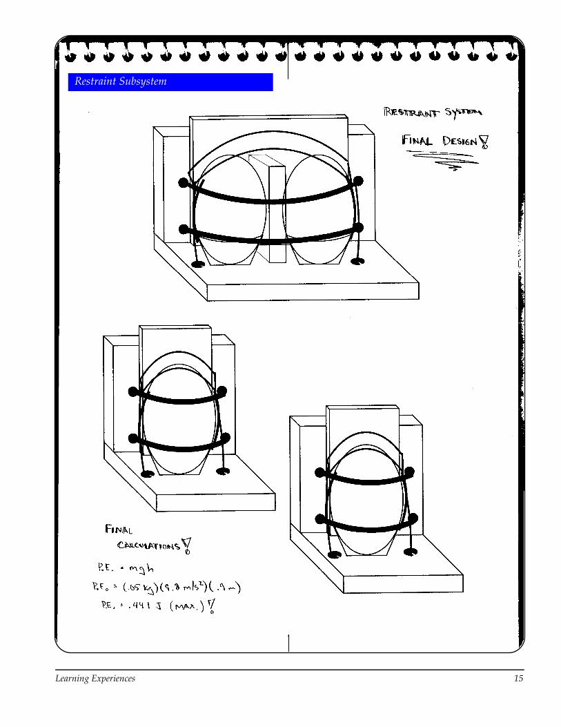
Restraint Subsystem

14 Mathematics, Science, and Technology
Restraint Subsystem
Learning Experiences 15
Restraint Subsystem

16 Mathematics, Science, and Technology
Car Body

Learning Experiences 17
Car Body

18 Mathematics, Science, and Technology
Car Body

Learning Experiences 19
Auto Safety Case StudyLog Book Assessment
“Bill and Ted’s Eggsellent Adventure”
Student: _____________________________________________
Assessment Scale:4: Mastery: Your work demonstrates excellence in this portion of the activity.3: Accomplished: Your work fulfills all of the objectives of this portion of the activity.2: Acceptable: Your work is acceptable, but needs minor revisions.1: Unacceptable: Your work is either incomplete, or requires major revisions.
1. Entries are made on a daily basis to document student’s work. ____________
2. Entries are thorough and complete containing all relevant material. ____________
3. Entries contain data, observations and an analysis of the investigations. ____________
4. Entries indicate use of problem solving and design techniques. ____________
5. Illustrations are included where appropriate, and they enhance the clarityof the logbook entries. ____________
6. Entries demonstrate student’s contribution to the group effort in this activity. ____________
Total: ____________

20 Mathematics, Science, and Technology
Auto Safety Case StudyAssessment of Activity
“Bill and Ted’s Eggsellent Adventure”
Design Team # ____ Subsystem Chief Engineers:
Restraint Subsystem: ________________________ Crumple Zone Subsystem:_________________________
Car Body Subsystem:________________________ Ergonomic Subsystem: ___________________________
Assessment Scale:
4: Mastery: Your work demonstrates excellence in this portion of the activity.
3: Accomplished: Your work fulfills all of the objectives of this portion of the activity.
2: Acceptable: Your work is acceptable, but needs minor revisions.
1: Unacceptable: Your work is either incomplete, or requires major revisions.
A. Restraint Subsystem
a) Preliminary designs are clearly identified with sketches. ________
b) All data collected for preliminary designs, calculations (analysis of data), and observations are clearly documented for each trial. ________
c) Design shows evidence of optimization. ________
d) Final solution is provided with suitable drawings. ________
e) Aconcise, written description documents your work. ________
B. Crumple Zone Subsystem
a) Preliminary designs are clearly identified with sketches. ________
b) All data collected for preliminary designs, calculations (analysis of data), and observations are clearly documented for each trial. ________
c) Design shows evidence of optimization. ________
d) Final solution is provided with suitable drawings. ________
e) Aconcise, written description documents your work. ________

Learning Experiences 21
C. Car Body Design Subsystem and Ergonomics Subsystem
a) Preliminary designs are clearly identified with sketches. ________
b) Safety systems are incorporated into a realistic car-body design. ________
c) Car body illustrates quality workmanship, and good utilization of both materials and equipment. ________
d) Effective use of ergonomics in restraint system design. ________
e) Visible indications that human factors engineering is incorporated into the vehicle design. ________
D . Survival of the Occupants (Bill & Ted)
Bill and Ted survive the crash unharmed (no cracks): (4) ________
Either Bill or Ted is injured (shell cracked) in the crash: (3) ________
Bill and Ted are both injured in the crash: (2) ________
Either Bill or Ted eggspires (cracks with leakage) in the crash: (1) ________
E. Presentation of Design to Class
a) Presentation was organized and well-planned. ________
b) Presentation was thorough and included all relevant content material. ________
c) Responses to questions were clear and appropriate. ________
d) Design was justified to class in presentation. ________
e) All design team members actively participated in presentation. ________
f) Presenters handled themselves in a professional manner. ________
g) Presentation included a variety of audiovisual media and visual aids. ________
F. Classwork/Groupwork
a) Student shows consistent effort. ________
b) Work started in a businesslike manner at bell. ________
c) Willingness to help other students. ________
d) Suitable class conduct displayed. ________
e) Student actively contributes to the group effort. ________
f) Student actively participates in the peer review process. ________
g) Student completes work in a timely fashion (at specified deadlines). ________
h) Student worked responsibly as a subsystem Chief Engineer, and was supportive to the other members of the design team. ________
Student’s Name: _____________________________________