Embed Size (px)
Citation preview
&PART I
MEMBRANES AND APPLICATIONS INWATER AND WASTEWATER
COPYRIG
HTED M
ATERIAL

&CHAPTER 1
Thin-Film Composite Membranes forReverse Osmosis
TADAHIRO UEMURA and MASAHIRO HENMI
Global Environment Research Laboratories, Toray Industries Inc., Otsu Shiga, Japan
1.1 INTRODUCTION
Because of vastly expanding populations, increasing water demand, and the deterioration ofwater resource quality and quantity, water is going to be the most precious resource in theworld. Thus, the 21st century is called the “water century.” In the 20th century, membranetechnologies made great progress, and commercial markets have been spreading veryrapidly and throughout the world. The key technologies fueling this progress are as follows:
1. Materials: Chemical design of high-performance materials suitable for each separ-ation mode
2. Morphology: Morphological design of high-performance membranes
3. Element/Module: Element and module design for high-performance membranes
4. Membrane Process: Plant design and operation technology
In 21st century, to solve these water problems, membranes technology is going to be furtherexpanded and new technology—further improvements of membrane performance, develop-ment of membrane systems, membranes stability such as antifouling membranes forwastewater treatment, and other highly qualified membranes—will be needed.
Among desalination technologies available today, reverse osmosis (RO) is regarded asthe most economical desalination process. Therefore, RO membranes have played crucialroles in obtaining fresh water from nonconventional water resources such as seawaterand wastewater.
1.2 APPLICATION OF RO MEMBRANES
Reverse osmosis membranes have been used widely for water treatment such as ultrapurewater makeup, pure boiler water makeup in industrial fields, seawater and brackish water
Advanced Membrane Technology and Applications. Edited by Norman N. Li, Anthony G. Fane,W. S. Winston Ho, and T. MatsuuraCopyright # 2008 John Wiley & Sons, Inc.
3
desalination in drinking water production, and wastewater treatment and reuse in industrial,agricultural, and indirect drinking water production as shown in Table 1.1.
The expansion of RO membrane applications promoted the redesign of suitablemembrane material to take into consideration chemical structure, membranes configuration,chemical stability, and ease of fabrication. And along with the improvements of themembranes, the applications are further developed.
1.3 MAJOR PROGRESS IN RO MEMBRANES
1.3.1 Cellulose Acetate Membrane
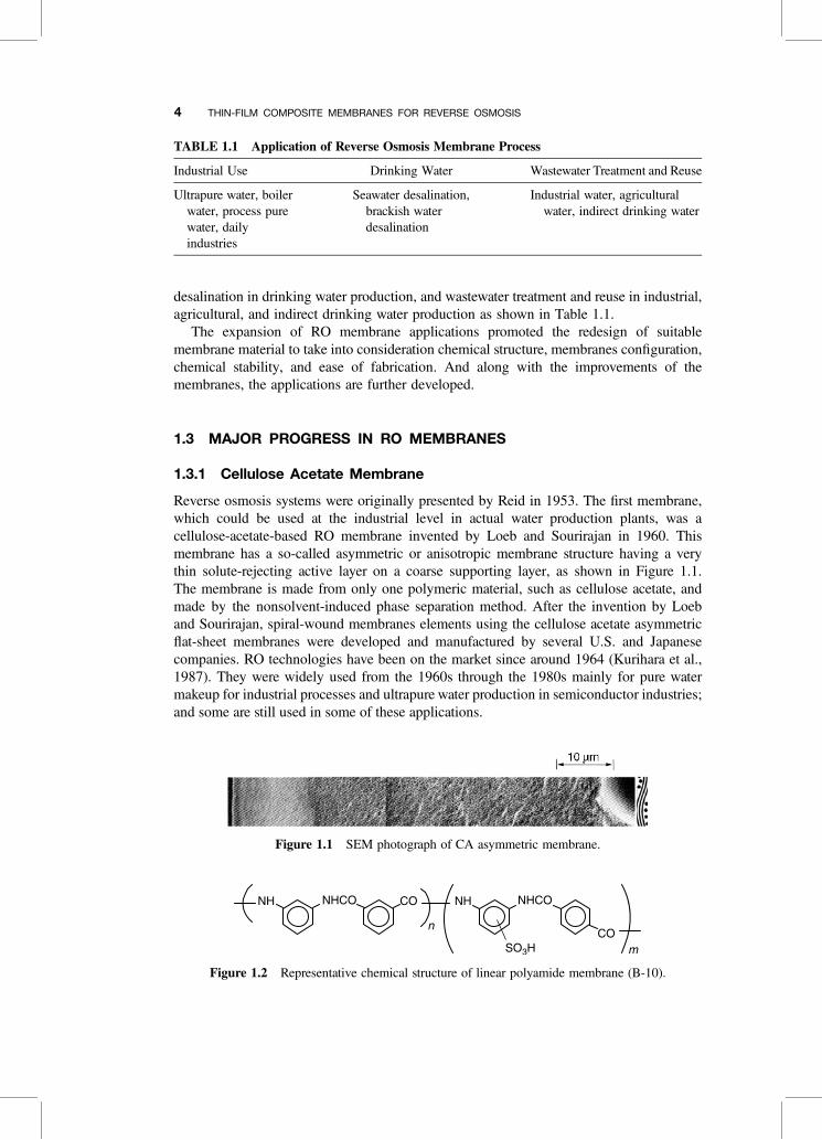
Reverse osmosis systems were originally presented by Reid in 1953. The first membrane,which could be used at the industrial level in actual water production plants, was acellulose-acetate-based RO membrane invented by Loeb and Sourirajan in 1960. Thismembrane has a so-called asymmetric or anisotropic membrane structure having a verythin solute-rejecting active layer on a coarse supporting layer, as shown in Figure 1.1.The membrane is made from only one polymeric material, such as cellulose acetate, andmade by the nonsolvent-induced phase separation method. After the invention by Loeband Sourirajan, spiral-wound membranes elements using the cellulose acetate asymmetricflat-sheet membranes were developed and manufactured by several U.S. and Japanesecompanies. RO technologies have been on the market since around 1964 (Kurihara et al.,1987). They were widely used from the 1960s through the 1980s mainly for pure watermakeup for industrial processes and ultrapure water production in semiconductor industries;and some are still used in some of these applications.
TABLE 1.1 Application of Reverse Osmosis Membrane Process
Industrial Use Drinking Water Wastewater Treatment and Reuse
Ultrapure water, boilerwater, process purewater, dailyindustries
Seawater desalination,brackish waterdesalination
Industrial water, agriculturalwater, indirect drinking water
Figure 1.1 SEM photograph of CA asymmetric membrane.
Figure 1.2 Representative chemical structure of linear polyamide membrane (B-10).
4 THIN-FILM COMPOSITE MEMBRANES FOR REVERSE OSMOSIS
TA
BL
E1.
2Su
mm
ary
ofM
embr
ane
Mat
eria
lsfo
rR
O
Mem
bran
eM
ater
ial
Mem
bran
eM
orph
olog
yM
odul
eC
onfi
gura
tion
Exa
mpl
esof
Mem
bran
ean
dM
odul
e,M
embr
ane
Sup
plie
rs
Cel
lulo
seac
etat
eS
pira
l1.
Tor
ay,U
OP,
envi
rong
enic
s,O
smon
ics,
Des
alin
atio
n,A
jax,
Hyd
rana
utic
s,D
aise
ru4.
Tor
ay-P
olya
mid
icac
id,D
uPo
nt-D
P-1
,M
onsa
nto
6.C
ella
nese
-Pol
yben
zim
idaz
ole
9.U
OP
-CT
A10
.Nor
thS
tar-
NS
-100
,U
OP
-PA
-300
,-1
00,L
P-3
00,R
C-1
0012
.Nor
thS
tar-
NS
-200
,O
smon
ics-
NS
-200
Env
iron
geni
cs-S
PFA
(NS
-200
),D
esal
inat
ion-
NS
-200
(?)
14.N
orth
Tri
angl
eIn
st.-
Pla
sma
Poly
m.
Tor
ay-P
EC
-100
0,F
ilmT
ec-F
T-3
0A
sahi
Gla
ss-M
VP,
Nih
onS
yoku
bai
Poly
amid
eH
eter
ocyc
licpo
lym
er
Cro
ss-l
inke
dw
ater
-sol
uble
poly
mer
Hol
low
fibe
r2.
Dow
,M
onsa
nto,
Toy
obo
5.D
uPo
nt7.
Cel
lane
se-P
olyb
ensi
mid
azol
e13
.FR
L-N
S-2
00,G
ulf
Sou
thR
esea
rch
Inst
.-N
S-1
00Po
lym
eriz
able
mon
omer
(cro
ss-l
inki
ng)
Tub
ular
3.U
OP,
Env
iron
geni
cs,
Uni
vers
alW
ater
Co.
Ray
pak,
Abc
or,
PC
I,N
itto,
Dai
seru
8.T
eijin
-PB
IL11
.Nor
thS
tar-
NS
-100
,O
ther
sS
umito
mo-
PAN
-Com
posi
teM
embe
rane
5
1.3.2 Aromatic Polyamide Hollow Fiber Membrane
Since then, there has been intensive and continuous R&D efforts mainly around the UnitedStates and Japan to meet the demands from commercial markets, and there exist manyinventions and breakthroughs in membrane materials and configurations to improve theperformances of membranes.
To overcome the problems of cellulose acetate membranes, many synthetic polymericmaterials for reverse osmosis were proposed, but except for one material, none of themproved successful. The only one material, which could remain on the market, was thelinear aromatic polyamide with pendant sulfonic acid groups, as shown in Figure 1.2.This material was proposed by DuPont, which fabricated very fine hollow fiber membranes;the modules of this membrane were designated B-9 and B-10. They have a high rejectionperformance, which can be used for single-stage seawater desalination. They were widelyused for mainly seawater or brackish water desalination and recovery of valuable materialssuch as electric deposition paints, until DuPont withdrew them from the market in 2001.
1.3.3 Composite Membrane
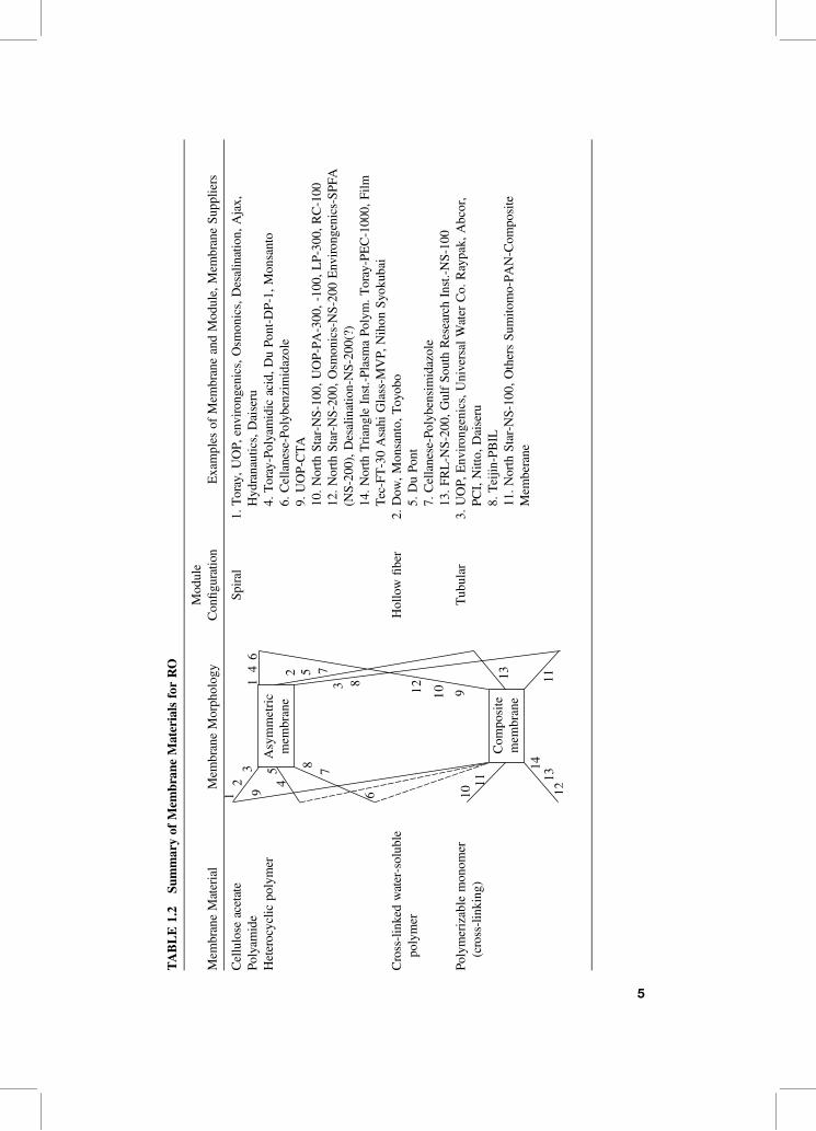
Another approach to obtain a high-performance RO membrane was investigated by someresearch institutes and companies in the 1970s. Many methods to prepare compositemembranes have been proposed, as shown in Table 1.2. In the early stage, very thinfilms of a cellulose acetate (CA) polymer coating on a substrate, such as a porous cellulosenitrate substrate, was tried. However, in spite of their efforts, this approach did not succeedin industrial membranes manufacturing.
The next approach used the interfacial polycondensation reaction to form a very thinpolymeric layer onto a substrate. Morgan first proposed this approach (Morgan, 1965),and then Scala et al. (1973) and Van Heuven (1976) actually applied this approach toobtain an RO membrane. But it was Cadotte who invented the high-performance membraneusing the in situ interfacial condensation method (Cadotte, 1985). In his method, interfacialcondensation reactions between polymeric polyamine and monomeric polyfunctional acidhalides or isocyanates takes place on a substrate material to deposit a thin film barrier onto asubstrate. Some of the composite membranes were succeeded in industrial fabrication byanother method, which was designated as PA-300 or RC-100.
Another preparation method for composite membrane is an in situ monomer con-densation method using the monomeric amine and monomeric acid halide, which wasalso invented by Cadotte. Then, many companies succeeded in developing compositemembranes using this method, and the membrane performance has been drasticallyimproved up to now. Now, composite membrane of cross-linked fully aromatic polyamideis regarded as the most popular and reliable material in the world. Permeate flow rate and itsquality have been improved 10 times greater than that of the beginning (Kurihara et al.,1987, 1994b).
1.4 TRENDS IN RO MEMBRANE TECHNOLOGY
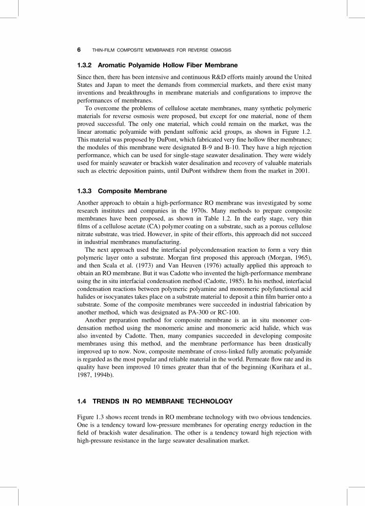
Figure 1.3 shows recent trends in RO membrane technology with two obvious tendencies.One is a tendency toward low-pressure membranes for operating energy reduction in thefield of brackish water desalination. The other is a tendency toward high rejection withhigh-pressure resistance in the large seawater desalination market.
6 THIN-FILM COMPOSITE MEMBRANES FOR REVERSE OSMOSIS
1.4.1 Progress of Low-Pressure Membrane Performancein Brackish Water Desalination
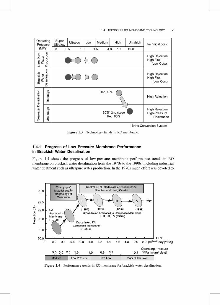
Figure 1.4 shows the progress of low-pressure membrane performance trends in ROmembrane on brackish water desalination from the 1970s to the 1990s, including industrialwater treatment such as ultrapure water production. In the 1970s much effort was devoted to
Figure 1.3 Technology trends in RO membrane.
Figure 1.4 Performance trends in RO membrane for brackish water desalination.
1.4 TRENDS IN RO MEMBRANE TECHNOLOGY 7
developing high-performance membrane materials and improving the membrane perform-ance. As a result performance was improved with a new developed material of cross-linkedaromatic polyamide and by developing membrane morphology and fabrication technology.The cross-linked fully aromatic polyamide composite membrane developed in 1987 hasfour or five times larger water flux and five times higher product water quality thanthose of the CA membrane (Kurihara et al., 1987). Since 1987, membrane performancehas been drastically developed. On the basis of the development of cross-linked fully aro-matic polyamide composite membranes, RO membrane performance of brackish waterdesalination has improved very rapidly. Typical performances of the RO elements forbrackish water desalination are shown in Table 1.3. The ultralow-pressure membrane,which can be used at ultralow pressures such as 0.75MPa, has been developed, whichsaves on the operating cost (Ikeda et al., 1996). And now the super-ultralow-pressure mem-brane elements, which can be used at super-ultralow-pressure, such as 0.5–0.3MPa, havebeen developed (Fusaoka, 1999). This membrane has three times the water permeabilitythan the ordinary low-pressure RO membrane. This membrane can operate with one-third the pressure of a low-pressure membrane.
1.4.2 Progress of RO Membranes for Seawater Desalination
The progress of RO membranes for seawater desalination is shown in Figure 1.5 (Kuriharaet al., 1994a). It is very important to increase the water recovery ratio on seawater desali-nation systems to achieve further cost reduction. Most seawater RO desalination systemsin use today are confined to approximately 40% conversion of the feed water (salt concen-tration 3.5%), since most of commercially available RO membrane do not allow forhigh-pressure operation of more than around 7.0MPa.
Recent progress on high-pressure–high-rejection spiral wound (SW) RO elements, com-bined with proven and innovative energy recovery and pumping devices, has opened newpossibilities to reduce investment and operating cost. The progress of RO seawater desali-nation from a point of view of water recovery is shown in Table 1.4 (Moch, 2000).
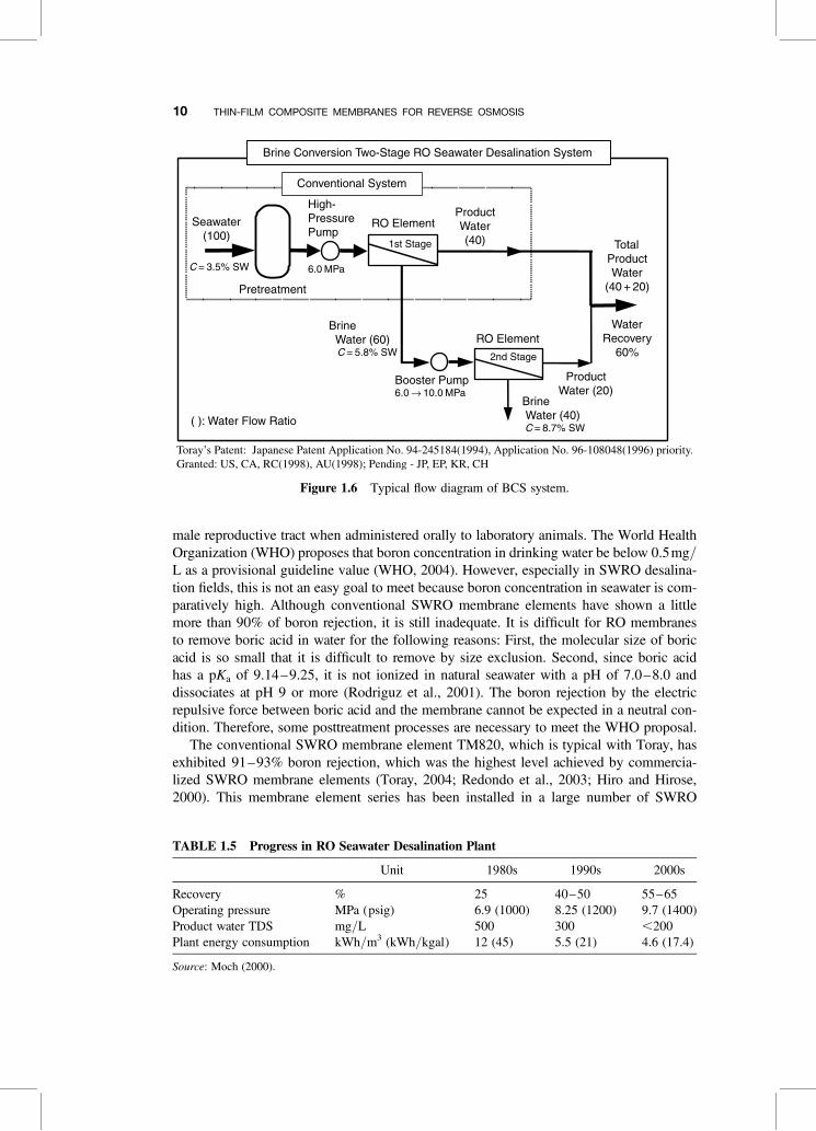
Toray has developed a new low-cost seawater desalination system called the BrineConversion Two-Stage (BCS) system, as shown in Figure 1.6, which provides 60%
TABLE 1.3 Typical Performance of Toray’s Brackish Water RO Elements
Type of Membrane
Low PressureUltralowPressure
Super-ultralowPressure
I II III IV
Name of membrane element(in market: year)
SU-720(1987)
SU-720L(1988)
SUL-G20(1996)
SUL-H20(1999)
PerformanceSalt rejection (%) 99.4 99.0 99.4 99.4Water permeability (m3/day) 26.0 22.0 26.0 26.0
Test conditionOperating pressure (MPa) 1.5 1.0 0.75 0.5Temperature (8C) 25 25 25 25Feed concentration (mg/L) 1500 1500 1500 1500Brine flow rate (L/min) 80 80 80 80
8 THIN-FILM COMPOSITE MEMBRANES FOR REVERSE OSMOSIS
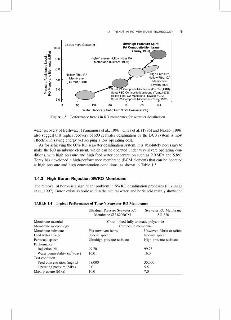
water recovery of freshwater (Yamamura et al., 1996). Ohya et al. (1996) and Nakao (1996)also suggest that higher recovery of RO seawater desalination by the BCS system is mosteffective in saving energy yet keeping a low operating cost.
As for achieving the 60% RO seawater desalination system, it is absolutely necessary tomake the RO membrane element, which can be operated under very severe operating con-ditions, with high pressure and high feed water concentration such as 9.0 MPa and 5.8%.Toray has developed a high-performance membrane (BCM element) that can be operatedat high pressure and high concentration conditions, as shown in Table 1.5.
1.4.3 High Boron Rejection SWRO Membrane
The removal of boron is a significant problem in SWRO desalination processes (Fukunagaet al., 1997). Boron exists as boric acid in the natural water, and boric acid mainly shows the
TABLE 1.4 Typical Performance of Toray’s Seawater RO Membranes
Ultrahigh Pressure Seawater ROMembrane SU-820BCM
Seawater RO MembraneSU-820
Membrane material Cross-linked fully aromatic polyamideMembrane morphology Composite membraneMembrane substrate Flat unwoven fabric Unwoven fabric or taffetaFeed water spacer Special spacer Normal spacerPermeate spacer Ultrahigh-pressure resistant High-pressure resistantPerformance
Rejection (%) 99.70 99.75Water permeability (m3/day) 16.0 16.0
Test conditionFeed concentration (mg/L) 58,000 35,000Operating pressure (MPa) 9.0 5.5
Max. pressure (MPa) 10.0 7.0
Figure 1.5 Performance trends in RO membranes for seawater desalination.
1.4 TRENDS IN RO MEMBRANE TECHNOLOGY 9
male reproductive tract when administered orally to laboratory animals. The World HealthOrganization (WHO) proposes that boron concentration in drinking water be below 0.5mg/L as a provisional guideline value (WHO, 2004). However, especially in SWRO desalina-tion fields, this is not an easy goal to meet because boron concentration in seawater is com-paratively high. Although conventional SWRO membrane elements have shown a littlemore than 90% of boron rejection, it is still inadequate. It is difficult for RO membranesto remove boric acid in water for the following reasons: First, the molecular size of boricacid is so small that it is difficult to remove by size exclusion. Second, since boric acidhas a pKa of 9.14–9.25, it is not ionized in natural seawater with a pH of 7.0–8.0 anddissociates at pH 9 or more (Rodriguz et al., 2001). The boron rejection by the electricrepulsive force between boric acid and the membrane cannot be expected in a neutral con-dition. Therefore, some posttreatment processes are necessary to meet the WHO proposal.
The conventional SWRO membrane element TM820, which is typical with Toray, hasexhibited 91–93% boron rejection, which was the highest level achieved by commercia-lized SWRO membrane elements (Toray, 2004; Redondo et al., 2003; Hiro and Hirose,2000). This membrane element series has been installed in a large number of SWRO
Figure 1.6 Typical flow diagram of BCS system.
TABLE 1.5 Progress in RO Seawater Desalination Plant
Unit 1980s 1990s 2000s
Recovery % 25 40–50 55–65Operating pressure MPa (psig) 6.9 (1000) 8.25 (1200) 9.7 (1400)Product water TDS mg/L 500 300 ,200Plant energy consumption kWh/m3 (kWh/kgal) 12 (45) 5.5 (21) 4.6 (17.4)
Source: Moch (2000).
10 THIN-FILM COMPOSITE MEMBRANES FOR REVERSE OSMOSIS
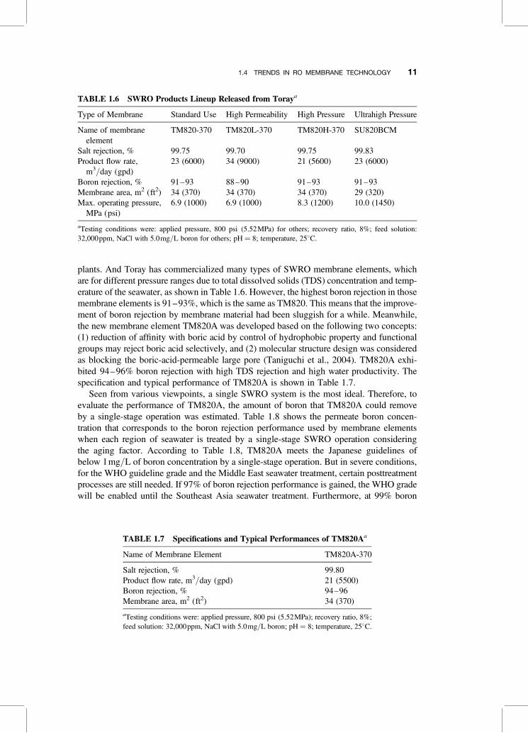
plants. And Toray has commercialized many types of SWRO membrane elements, whichare for different pressure ranges due to total dissolved solids (TDS) concentration and temp-erature of the seawater, as shown in Table 1.6. However, the highest boron rejection in thosemembrane elements is 91–93%, which is the same as TM820. This means that the improve-ment of boron rejection by membrane material had been sluggish for a while. Meanwhile,the new membrane element TM820A was developed based on the following two concepts:(1) reduction of affinity with boric acid by control of hydrophobic property and functionalgroups may reject boric acid selectively, and (2) molecular structure design was consideredas blocking the boric-acid-permeable large pore (Taniguchi et al., 2004). TM820A exhi-bited 94–96% boron rejection with high TDS rejection and high water productivity. Thespecification and typical performance of TM820A is shown in Table 1.7.
Seen from various viewpoints, a single SWRO system is the most ideal. Therefore, toevaluate the performance of TM820A, the amount of boron that TM820A could removeby a single-stage operation was estimated. Table 1.8 shows the permeate boron concen-tration that corresponds to the boron rejection performance used by membrane elementswhen each region of seawater is treated by a single-stage SWRO operation consideringthe aging factor. According to Table 1.8, TM820A meets the Japanese guidelines ofbelow 1mg/L of boron concentration by a single-stage operation. But in severe conditions,for the WHO guideline grade and the Middle East seawater treatment, certain posttreatmentprocesses are still needed. If 97% of boron rejection performance is gained, the WHO gradewill be enabled until the Southeast Asia seawater treatment. Furthermore, at 99% boron
TABLE 1.6 SWRO Products Lineup Released from Toraya
Type of Membrane Standard Use High Permeability High Pressure Ultrahigh Pressure
Name of membraneelement
TM820-370 TM820L-370 TM820H-370 SU820BCM
Salt rejection, % 99.75 99.70 99.75 99.83Product flow rate,
m3/day (gpd)23 (6000) 34 (9000) 21 (5600) 23 (6000)
Boron rejection, % 91–93 88–90 91–93 91–93Membrane area, m2 (ft2) 34 (370) 34 (370) 34 (370) 29 (320)Max. operating pressure,
MPa (psi)6.9 (1000) 6.9 (1000) 8.3 (1200) 10.0 (1450)
aTesting conditions were: applied pressure, 800 psi (5.52MPa) for others; recovery ratio, 8%; feed solution:32,000ppm, NaCl with 5.0mg/L boron for others; pH ¼ 8; temperature, 258C.
TABLE 1.7 Specifications and Typical Performances of TM820Aa
Name of Membrane Element TM820A-370
Salt rejection, % 99.80Product flow rate, m3/day (gpd) 21 (5500)Boron rejection, % 94–96Membrane area, m2 (ft2) 34 (370)
aTesting conditions were: applied pressure, 800 psi (5.52MPa); recovery ratio, 8%;feed solution: 32,000ppm, NaCl with 5.0mg/L boron; pH ¼ 8; temperature, 258C.
1.4 TRENDS IN RO MEMBRANE TECHNOLOGY 11
rejection performance, the WHO guideline grade will be enabled even in the Middle Eastseawater treatment.
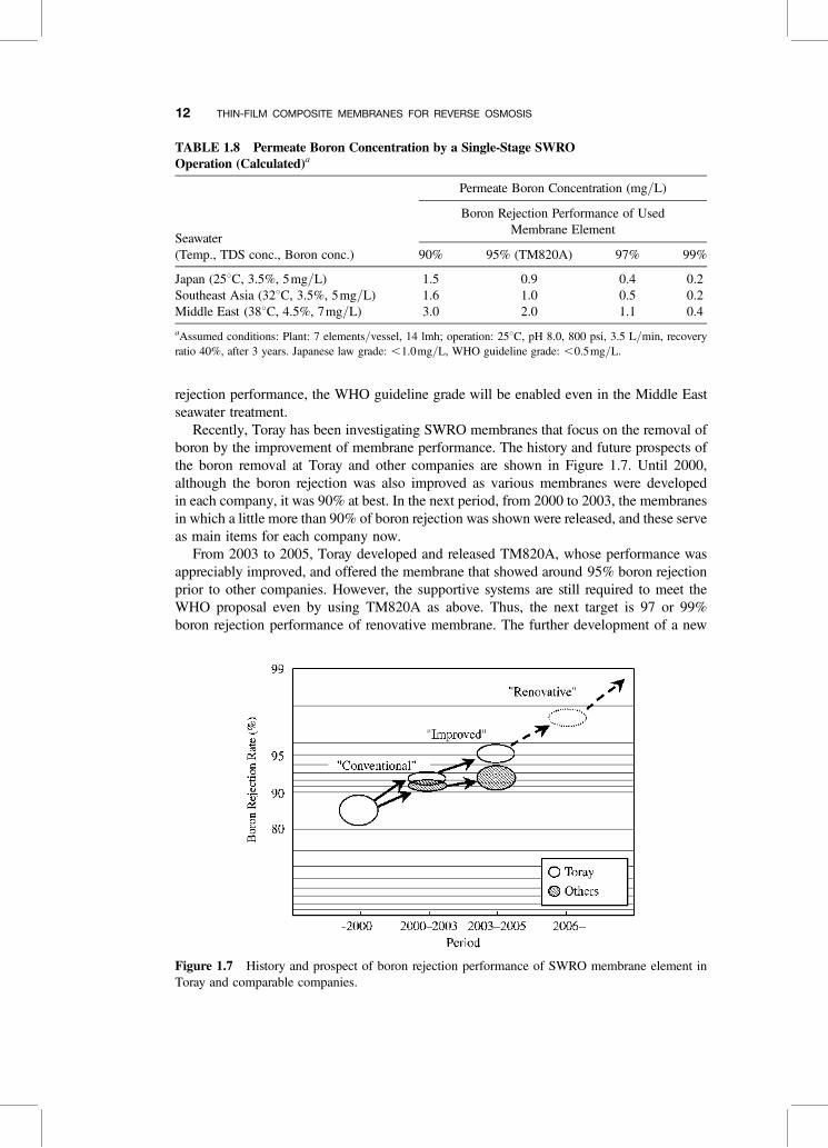
Recently, Toray has been investigating SWRO membranes that focus on the removal ofboron by the improvement of membrane performance. The history and future prospects ofthe boron removal at Toray and other companies are shown in Figure 1.7. Until 2000,although the boron rejection was also improved as various membranes were developedin each company, it was 90% at best. In the next period, from 2000 to 2003, the membranesin which a little more than 90% of boron rejection was shown were released, and these serveas main items for each company now.
From 2003 to 2005, Toray developed and released TM820A, whose performance wasappreciably improved, and offered the membrane that showed around 95% boron rejectionprior to other companies. However, the supportive systems are still required to meet theWHO proposal even by using TM820A as above. Thus, the next target is 97 or 99%boron rejection performance of renovative membrane. The further development of a new
TABLE 1.8 Permeate Boron Concentration by a Single-Stage SWROOperation (Calculated)a
Seawater(Temp., TDS conc., Boron conc.)
Permeate Boron Concentration (mg/L)
Boron Rejection Performance of UsedMembrane Element
90% 95% (TM820A) 97% 99%
Japan (258C, 3.5%, 5mg/L) 1.5 0.9 0.4 0.2Southeast Asia (328C, 3.5%, 5mg/L) 1.6 1.0 0.5 0.2Middle East (388C, 4.5%, 7mg/L) 3.0 2.0 1.1 0.4
aAssumed conditions: Plant: 7 elements/vessel, 14 lmh; operation: 258C, pH 8.0, 800 psi, 3.5 L/min, recoveryratio 40%, after 3 years. Japanese law grade: ,1.0mg/L, WHO guideline grade: ,0.5mg/L.
Figure 1.7 History and prospect of boron rejection performance of SWRO membrane element inToray and comparable companies.
12 THIN-FILM COMPOSITE MEMBRANES FOR REVERSE OSMOSIS
renovative membrane that can meet the WHO proposal for every seawater continues(Tomioka et al., 2005). Table 1.9 summarizes large seawater RO desalination plantsaround the world. TM820A is installed in a large seawater RO desalination plant in Singapore.
1.5 REVERSE OSMOSIS/BIOFOULING PROTECTION
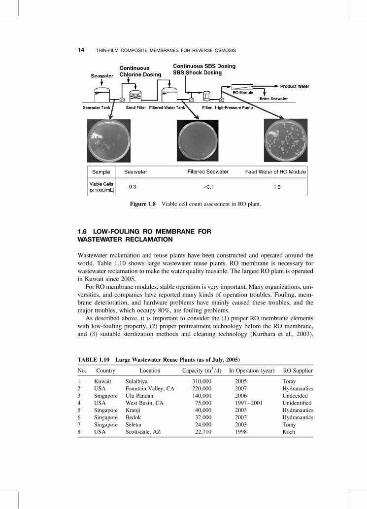
Biofouling has been regarded as the most serious problem in the operation of SWRO plants.The usual method to prevent biofouling is continuous chlorine dosing to intake seawaterwith sodium bisulfate (SBS) dosing at the RO portion. However, membranes performancedeterioration occurred by oxidation in case of both polyamide and cellulose acetatemembranes, and biofouling has not been solved yet. Toray has developed a new methodthat is effective to prevent biofouling on SWRO membranes and verified its effectivenessat actual plants.
First of all, by measuring the viable counts of bacteria at a plant, in case of the continu-ous chlorine/SBS dosing method, it was found that a number of bacteria drasticallyincreased immediately after SBS dosing, as shown in Figure 1.8, and most of these bacteriawere quite different from those found in raw seawater. Currently, the addition of SBS tofeed water at relatively high concentration has been used for sterilization of RO membranes.However, when SBS was added to seawater, the pH was just dropped to 6, and most of thebacteria harbored in water were still alive. This result indicates that the sterilization ability ofSBS is due to lower pH, and oxygen consumption with SBS only plays a role to repress thecell growth. Finally, Toray has developed a new agent, MT-901, which is effective in pre-venting biofouling on RO membranes. Adding MT-901 to seawater instead of SBS effec-tively killed bacteria in a few samples of seawater within a short time.
Finally, the effect of this method was verified at an SWRO plant. In this plant, when feedwater was chlorinated and dechlorinated with SBS continuously and RO membranemodules were treated with SBS intermittently, differentiation pressure of the moduleincreased gradually. MT-901 was used for membrane module treatment in place of SBSand the differential pressure decreased within 10 days. Moreover, using an intermittentchlorination method was effective to maintain the initial differential pressure with less con-centration of MT-901 (Kallenberg et al., 1999).
TABLE 1.9 Large Seawater Desalination Plants Utilizing RO Process (as of July, 2005)
No. Country Location Capacity (m3/d) In Operation (year) Membrane Supplier
1 Israel Ashkelon 272,520 2005 Dow2 UAE Taweelah 227,300 2006 Undecided3 Algeria Hamma 200,000 2006 Undecided4 UAE Fujairah 170,000 2003 Hydranautics5 Trinidad
& TobagoPoint Lisa 136,000 2002 Toray
5 Singapore Tuas 136,000 2005 Toray7 Saudi Arabia Tanbu 128,000 1995 Toyobo8 Spain Carponeras 120,000 2001 Hydranautics9 Israel Palmachim 92,250 2006 Toray10 Saudi Arabia Al Jubail III 90,900 2000 DuPont/Toray
1.5 REVERSE OSMOSIS/BIOFOULING PROTECTION 13
1.6 LOW-FOULING RO MEMBRANE FORWASTEWATER RECLAMATION
Wastewater reclamation and reuse plants have been constructed and operated around theworld. Table 1.10 shows large wastewater reuse plants. RO membrane is necessary forwastewater reclamation to make the water quality reusable. The largest RO plant is operatedin Kuwait since 2005.
For RO membrane modules, stable operation is very important. Many organizations, uni-versities, and companies have reported many kinds of operation troubles. Fouling, mem-brane deterioration, and hardware problems have mainly caused these troubles, and themajor troubles, which occupy 80%, are fouling problems.
As described above, it is important to consider the (1) proper RO membrane elementswith low-fouling property, (2) proper pretreatment technology before the RO membrane,and (3) suitable sterilization methods and cleaning technology (Kurihara et al., 2003).
Figure 1.8 Viable cell count assessment in RO plant.
TABLE 1.10 Large Wastewater Reuse Plants (as of July, 2005)
No. Country Location Capacity (m3/d) In Operation (year) RO Supplier
1 Kuwait Sulaibiya 310,000 2005 Toray2 USA Fountain Valley, CA 220,000 2007 Hydranautics3 Singapore Ulu Pandan 140,000 2006 Undecided4 USA West Basin, CA 75,000 1997–2001 Unidentified5 Singapore Kranji 40,000 2003 Hydranautics6 Singapore Bedok 32,000 2003 Hydranautics7 Singapore Seletar 24,000 2003 Toray8 USA Scottsdale, AZ 22,710 1998 Koch
14 THIN-FILM COMPOSITE MEMBRANES FOR REVERSE OSMOSIS
The reasons for fouling of RO membrane are reported as consisting of chemical fouling,biological fouling, and scale precipitation.
It is estimated that chemical fouling is caused by the adsorption of organic materials suchas humic substances and surfactants in the feed water or on the membrane surface. Humicsubstances have various chemical structures depending on the water origin, such as landwater or seawater, and regions in the world. However, it has both hydrophobic groups ofaromatic and linear structure and ionic groups of amino acid and carboxylic acid. Thematerial of RO membrane is polyamide with hydrophobic and ionic properties. As men-tioned above, chemical fouling depends on hydrophobic interaction and electrostatic inter-action between organic materials in the feed water and membrane surface.
On the other hand, in case of biological fouling, the following estimations are reported:(1) microbe adsorption by hydrophobic or electrostatic interaction, (2) propagation ofmicrobe with nutrition in the feed water, and (3) deposition of exhaust material of biologicalmetabolism. Case 1 is a reversible phenomenon; however, cases 2 and 3 are irreversiblephenomena, which are difficult to remove by simple chemical cleaning.
As a result of R&D activities, Toray has developed low-fouling RO membrane for waste-water reclamation. The low-fouling RO membrane has the same level of pure water perme-ability as conventional RO membranes, SU-700 and SUL-G, and also has low-foulingproperty with keeping water permeability against chemical and biological fouling duringthe operation (Yamamura et al., 2002).
The low-fouling property of membranes is evaluated with a nonionic surfactant aqueoussolution. Test result shows that, in operation, low-fouling RO membrane has a relativelysmall permeability declaration ratio of 27%, compared with initial pure water permeabilityand shows stable operation. On the other hand, conventional fully aromatic polyamidemembranes, SU-700 and SUL-G, show 36–47% declaration ratio, even if they showstable operation. And concerning the chemical cleaning properties, low-fouling RO mem-brane shows better recovery of permeability after chemical cleaning.
To evaluate the fouling property against microbes, adsorption property of a certainhydrophobic microbe and other hydrophilic microbes were measured. The hydrophobicmicrobe was severely adsorbed to conventional RO membranes and caused biologicalfouling of RO membranes. In case of low-fouling RO membranes, the adsorption propertyof the hydrophobic microbe is quite low, which is less than one-tenth of conventional ROmembranes. Initial performance of low-fouling RO membrane element TML-20 isdescribed in Table 1.11.
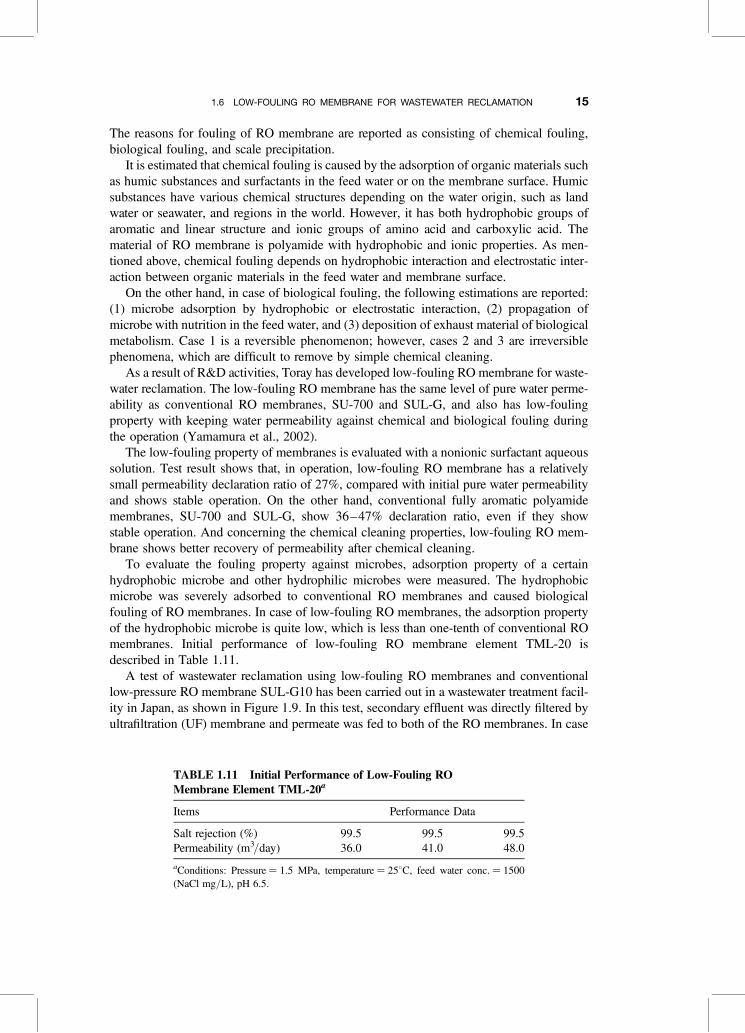
A test of wastewater reclamation using low-fouling RO membranes and conventionallow-pressure RO membrane SUL-G10 has been carried out in a wastewater treatment facil-ity in Japan, as shown in Figure 1.9. In this test, secondary effluent was directly filtered byultrafiltration (UF) membrane and permeate was fed to both of the RO membranes. In case
TABLE 1.11 Initial Performance of Low-Fouling ROMembrane Element TML-20a
Items Performance Data
Salt rejection (%) 99.5 99.5 99.5Permeability (m3/day) 36.0 41.0 48.0
aConditions: Pressure ¼ 1.5 MPa, temperature ¼ 258C, feed water conc. ¼ 1500(NaCl mg/L), pH 6.5.
1.6 LOW-FOULING RO MEMBRANE FOR WASTEWATER RECLAMATION 15
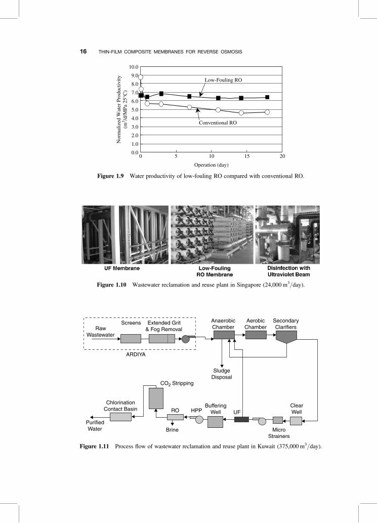
Figure 1.9 Water productivity of low-fouling RO compared with conventional RO.
Figure 1.10 Wastewater reclamation and reuse plant in Singapore (24,000 m3/day).
Figure 1.11 Process flow of wastewater reclamation and reuse plant in Kuwait (375,000 m3/day).
16 THIN-FILM COMPOSITE MEMBRANES FOR REVERSE OSMOSIS
of the SUL-G membrane, water permeability dropped to 60% of initial permeability in aday due to biological fouling; however, the permeability drop of low-fouling RO TML20was smaller than that of SUL-G and the stable operation has been performed.
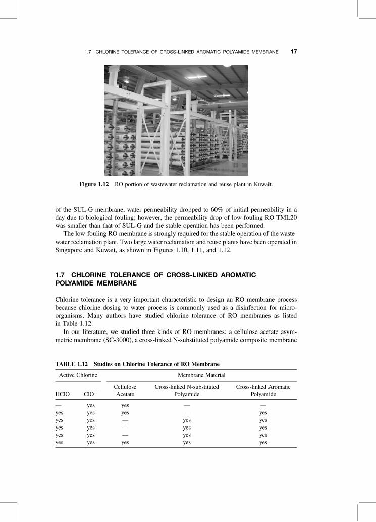
The low-fouling RO membrane is strongly required for the stable operation of the waste-water reclamation plant. Two large water reclamation and reuse plants have been operated inSingapore and Kuwait, as shown in Figures 1.10, 1.11, and 1.12.
1.7 CHLORINE TOLERANCE OF CROSS-LINKED AROMATICPOLYAMIDE MEMBRANE
Chlorine tolerance is a very important characteristic to design an RO membrane processbecause chlorine dosing to water process is commonly used as a disinfection for micro-organisms. Many authors have studied chlorine tolerance of RO membranes as listedin Table 1.12.
In our literature, we studied three kinds of RO membranes: a cellulose acetate asym-metric membrane (SC-3000), a cross-linked N-substituted polyamide composite membrane
Figure 1.12 RO portion of wastewater reclamation and reuse plant in Kuwait.
TABLE 1.12 Studies on Chlorine Tolerance of RO Membrane
Active Chlorine Membrane Material
HClO ClO2
CelluloseAcetate
Cross-linked N-substitutedPolyamide
Cross-linked AromaticPolyamide
— yes yes — —yes yes yes — yesyes yes — yes yesyes yes — yes yesyes yes — yes yesyes yes yes yes yes
1.7 CHLORINE TOLERANCE OF CROSS-LINKED AROMATIC POLYAMIDE MEMBRANE 17
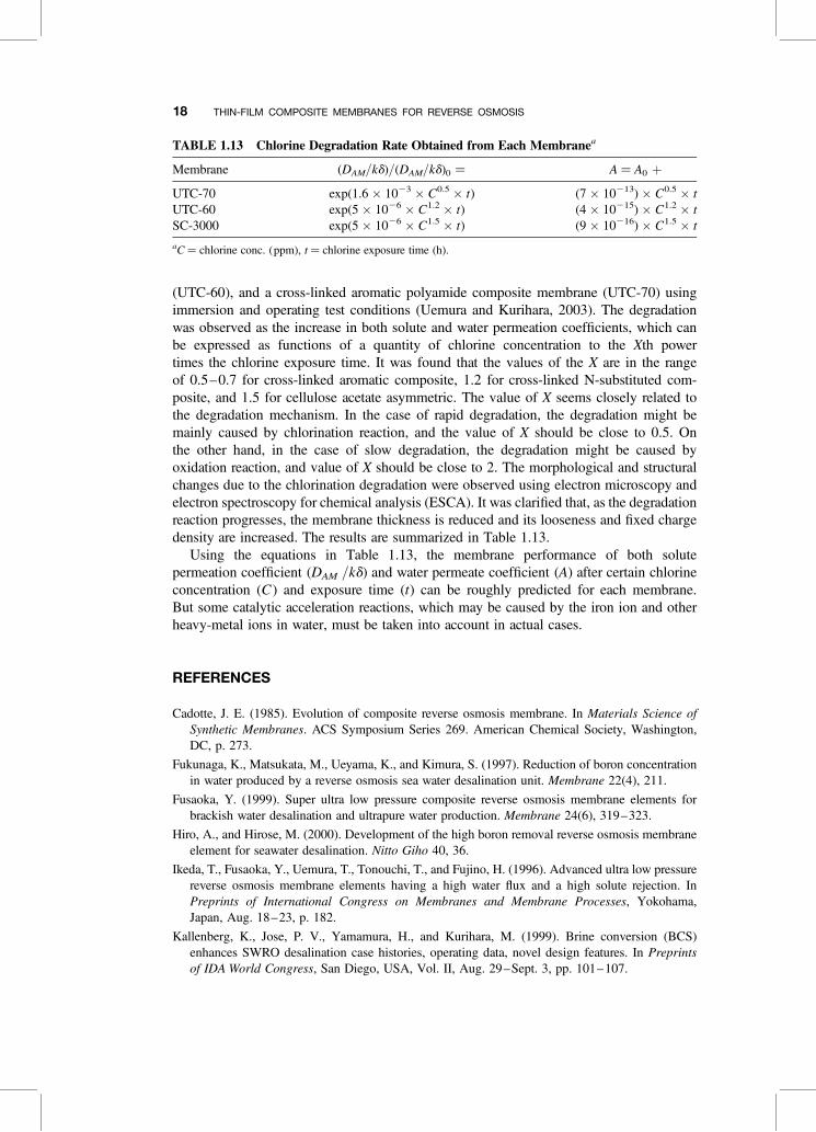
(UTC-60), and a cross-linked aromatic polyamide composite membrane (UTC-70) usingimmersion and operating test conditions (Uemura and Kurihara, 2003). The degradationwas observed as the increase in both solute and water permeation coefficients, which canbe expressed as functions of a quantity of chlorine concentration to the Xth powertimes the chlorine exposure time. It was found that the values of the X are in the rangeof 0.5–0.7 for cross-linked aromatic composite, 1.2 for cross-linked N-substituted com-posite, and 1.5 for cellulose acetate asymmetric. The value of X seems closely related tothe degradation mechanism. In the case of rapid degradation, the degradation might bemainly caused by chlorination reaction, and the value of X should be close to 0.5. Onthe other hand, in the case of slow degradation, the degradation might be caused byoxidation reaction, and value of X should be close to 2. The morphological and structuralchanges due to the chlorination degradation were observed using electron microscopy andelectron spectroscopy for chemical analysis (ESCA). It was clarified that, as the degradationreaction progresses, the membrane thickness is reduced and its looseness and fixed chargedensity are increased. The results are summarized in Table 1.13.
Using the equations in Table 1.13, the membrane performance of both solutepermeation coefficient (DAM /kd) and water permeate coefficient (A) after certain chlorineconcentration (C ) and exposure time (t) can be roughly predicted for each membrane.But some catalytic acceleration reactions, which may be caused by the iron ion and otherheavy-metal ions in water, must be taken into account in actual cases.
REFERENCES
Cadotte, J. E. (1985). Evolution of composite reverse osmosis membrane. In Materials Science ofSynthetic Membranes. ACS Symposium Series 269. American Chemical Society, Washington,DC, p. 273.
Fukunaga, K., Matsukata, M., Ueyama, K., and Kimura, S. (1997). Reduction of boron concentrationin water produced by a reverse osmosis sea water desalination unit. Membrane 22(4), 211.
Fusaoka, Y. (1999). Super ultra low pressure composite reverse osmosis membrane elements forbrackish water desalination and ultrapure water production. Membrane 24(6), 319–323.
Hiro, A., and Hirose, M. (2000). Development of the high boron removal reverse osmosis membraneelement for seawater desalination. Nitto Giho 40, 36.
Ikeda, T., Fusaoka, Y., Uemura, T., Tonouchi, T., and Fujino, H. (1996). Advanced ultra low pressurereverse osmosis membrane elements having a high water flux and a high solute rejection. InPreprints of International Congress on Membranes and Membrane Processes, Yokohama,Japan, Aug. 18–23, p. 182.
Kallenberg, K., Jose, P. V., Yamamura, H., and Kurihara, M. (1999). Brine conversion (BCS)enhances SWRO desalination case histories, operating data, novel design features. In Preprintsof IDA World Congress, San Diego, USA, Vol. II, Aug. 29–Sept. 3, pp. 101–107.
TABLE 1.13 Chlorine Degradation Rate Obtained from Each Membranea
Membrane (DAM/kd)/(DAM/kd)0 ¼ A ¼ A0 þ
UTC-70 exp(1.6 � 1023 � C0.5 � t) (7 � 10213) � C0.5 � tUTC-60 exp(5 � 1026 � C1.2 � t) (4 � 10215) � C1.2 � tSC-3000 exp(5 � 1026 � C1.5 � t) (9 � 10216) � C1.5 � t
aC ¼ chlorine conc. (ppm), t ¼ chlorine exposure time (h).
18 THIN-FILM COMPOSITE MEMBRANES FOR REVERSE OSMOSIS
Kurihara, M., Fusaoka, Y., Sasaki, T., Bairinji, R., and Uemura, T. (1994a). Development ofcross-linked fully aromatic polyamide ultra-thin composite membranes for seawater desalination.Desalination 96, 133.
Kurihara, M., Himeshima, Y., and Uemura, T. (1987). In Preprints of ICOM, p. 428.
Kurihara, M., Matsuka, N., Fusaoka, Y., and Henmi, M. (2003). Newly developed wastewatertreatment systems using separation membranes. In Proceedings Water Reuse & DesalinationConference, Suntec Singapore, Singapore, Feb. 25–27.
Kurihara, M., Uemura, T., Himeshima, Y., Ueno, K., and Bairinji, Y. (1994b). Development ofcrosslinked aromatic polyamide composite reverse osmosis membrane. Nippon Kagaku Kaishi1994(2), 97–107.
Moch, I. (2000). The case for and feasibility of very high recovery sea water reverse osmosis plants.In Preprints of ADA Conference, Lake Tahoe, USA.
Morgan, P. W. (1965). Condensation polymers: By interfacial and solution methods. In PolymerReviews, Vol. 10. Wiley, New York.
Nakao, S. (1996). Sea water desalination process for high recovery of fresh water by reverse osmosis.Bull. Soc. Sea Water Sci. Japn. 50(6), 406–412.
Ohya, H., Suzuki, T., and Nakao, S. (1996). Proposal and technological breakthrough of an integratedsystem for the complete usage of sea water. Bull. Soc. Sea Water Sci. Japn. 50(6), 389–395.
Redondo, J., Busch, M., and Witte, J. D. (2003). Boron removal from seawater using FILMTECTM
high rejection SWRO membranes. Desalination 156, 229.
Rodriguez, M., Ruiz, A. F., Chilon, M. F., and Rico, D. P. (2001). Influence of pH in the eliminationof boron by means of reverse osmosis. Desalination 140, 145.
Scala, R. C., Ciliberti, D. F., and Berg, D. (1973). Interface condensation desalination membrane.U.S. Patent 3,744,642.
Taniguchi, M., Fusaoka, Y., Nishikawa, T., and Kurihara, M. (2004). Boron removal in RO seawaterdesalination. Desalination 167, 419.
Tomioka, H., Taniguchi, M., Okazaki, M., Goto, S., Uemura, T., and Kurihara, M. (2005). Milestoneof high boron rejection seawater RO membrane. In Proceedings of IDA World Congress onDesalination and Water Reuse, Singapore, Sept. 11–14.
Toray (2004). Brochure of TM800. Tokyo, Japan.
Uemura, T., and Kurihara, M. (2003). Chlorine resistance of reverse osmosis membranes andchanges in membrane structure and performance caused by chlorination degradation. Bull. Soc.Sea Water Sci. Jpn. 57, 498.
World Health Organization (WHO) (2004). Guidelines for Drinking Water Quality, 3rd ed. WHO,Geneva.
Van Heuven, J. W. (1976). Dynamic membrane. U.S. Patent 3,996,318.
Yamamura, H., Henmi, M., and Inoue, T. (2002). In Development innovative MF and RO membranefor wastewater treatment and reclamation. In Proceedings of the 2nd International Conference onApplication of Membrane Technology, Beijing, China, Sept. 27–29.
Yamamura, H., Kurihara, M., and Maeda, K. (1994, 1996). Japanese Patent Applications H06-245184and H08-108048.
REFERENCES 19


![INDEX 1205 [catalogimages.wiley.com]](https://img.dokumen.tips/doc/110x75/6285875d2522e359a13adc54/index-1205-.jpg)
