Embed Size (px)
Citation preview
MacKays to Peka Peka Project Assessment of Environmental Effects report
Chapter 7 Operation of the Project | 139
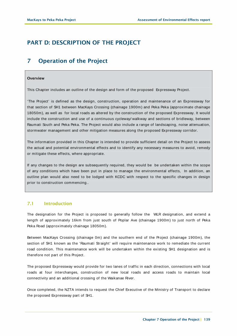
PART D: DESCRIPTION OF THE PROJECT
7 Operation of the Project
Overview
This Chapter includes an outline of the design and form of the proposed Expressway Project.
‘The Project’ is defined as the design, construction, operation and maintenance of an Expressway for that section of SH1 between MacKays Crossing (chainage 1900m) and Peka Peka (approximate chainage 18050m), as well as for local roads as altered by the construction of the proposed Expressway. It would include the construction and use of a continuous cycleway/walkway and sections of bridleway, between Raumati South and Peka Peka. The Project would also include a range of landscaping, noise attenuation, stormwater management and other mitigation measures along the proposed Expressway corridor.
The information provided in this Chapter is intended to provide sufficient detail on the Project to assess the actual and potential environmental effects and to identify any necessary measures to avoid, remedy or mitigate these effects, where appropriate.
If any changes to the design are subsequently required, they would be be undertaken within the scope of any conditions which have been put in place to manage the environmental effects, In addition, an outline plan would also need to be lodged with KCDC with respect to the specific changes in design prior to construction commencing..
7.1 Introduction
The designation for the Project is proposed to generally follow the WLR designation, and extend a length of approximately 16km from just south of Poplar Ave (chainage 1900m) to just north of Peka Peka Road (approximately chainage 18050m).
Between MacKays Crossing (chainage 0m) and the southern end of the Project (chainage 1900m), the section of SH1 known as the ‘Raumati Straight’ will require maintenance work to remediate the current road condition. This maintenance work will be undertaken within the existing SH1 designation and is therefore not part of this Project.
The proposed Expressway would provide for two lanes of traffic in each direction, connections with local roads at four interchanges, construction of new local roads and access roads to maintain local connectivity and an additional crossing of the Waikanae River.
Once completed, the NZTA intends to request the Chief Executive of the Ministry of Transport to declare the proposed Expressway part of SH1.
MacKays to Peka Peka Project Assessment of Environmental Effects report
Chapter 7 Operation of the Project | 140
The existing section of SH1 between MacKays Crossing and Peka Peka would likely become a local arterial road (subject to the Chief Executive at Ministry of Transport revoking its current State highway status).
The Project would include the following principal design features:
• A four lane median divided Expressway (two traffic lanes in each direction);
• Partial interchange at Poplar Avenue;
• Full interchange at Kāpiti Road;
• Four lane bridge over the Waikanae River;
• Full interchange at Te Moana Road;
• Partial interchange at Peka Peka Road;
• Grade separated overbridges and underbridges to cross some local roads and watercourses and parts of the proposed Expressway;
• Stormwater treatment and attenuation facilities;
• Provision of a shared cycleway/walkway, alongside but separate to the proposed Expressway; and
• Provision of a bridleway over sections of the corridor.
Where local roads are referred to in this Chapter, they are generally limited to sections of local road inside the proposed designation. This would in most instances include the sections of local roads that the proposed Expressway connects with and/or crosses.
Further technical information relating to the Project is provided within Part G of this AEE report, the relevant Technical Reports in Volume 3 and the Plan Set within Volume 5. These documents have been cross referenced throughout this Chapter.
7.1.1 Design Philosophy Statement
A Design Philosophy Statement (DPS) has been produced for key elements of the Project. This DPS covers the design philosophy for the proposed Expressway and for those sections of the local road network that are affected by the proposed Expressway construction. The DPS identifies the standards, guidelines and key criteria that will be used in the design of the Project. Where relevant, the DPS provides commentary on variations from standards and consideration of design alternatives.
The NZTA’s Design Philosophy document can be found within Technical Report 1, Volume 3.
7.1.2 Urban and Landscape Design Framework
The purpose of the Urban and Landscape Design Framework (ULDF) for the Project is to:
• Demonstrate how the design of the Project supports the NZTA’s strategic commitment to high quality urban design outcomes;
MacKays to Peka Peka Project Assessment of Environmental Effects report
Chapter 7 Operation of the Project | 141
• Demonstrate alignment between the NZTA and KCDC in the planning, transport and urban design initiatives for the wider area;
• Seek to ensure that the urban and landscape design concepts for the Project are appropriately defined, developed and implemented;
• Promote a consistent design quality throughout the development and delivery of the Project;
• Promote integration of the Project with public aspirations and plans for land use and development in the surrounding area.
The ULDF focuses primarily on design aspects of the proposed Expressway, rather than an assessment of specific environmental effects. It includes an analysis of the existing landscape, and the consequential implications for the design of the proposed Expressway. A series of design principles were developed and these were taken into account in the selection of route options, refinement of the alignment and the development of design details. The ULDF report documents background detail of the existing environment and the design rationale that is relevant to, and has informed, this assessment.
The ULDF is contained in Technical Report 5, Volume5.
7.2 General project description
A general description of the proposed Expressway design is provided below. The Sector description within Section 7.3 of this Chapter details where the design would deviate from the general design. As a road controlling authority, the NZTA would have the ability to alter some of these measures in future if that was appropriate for the efficient or safe operation of the road and/or as technology and road management methodology evolves; for example, new forms of barriers might allow changes in the design and location of barriers and medians.
7.2.1 Road design
a. Proposed Expressway Design
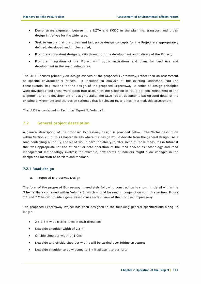
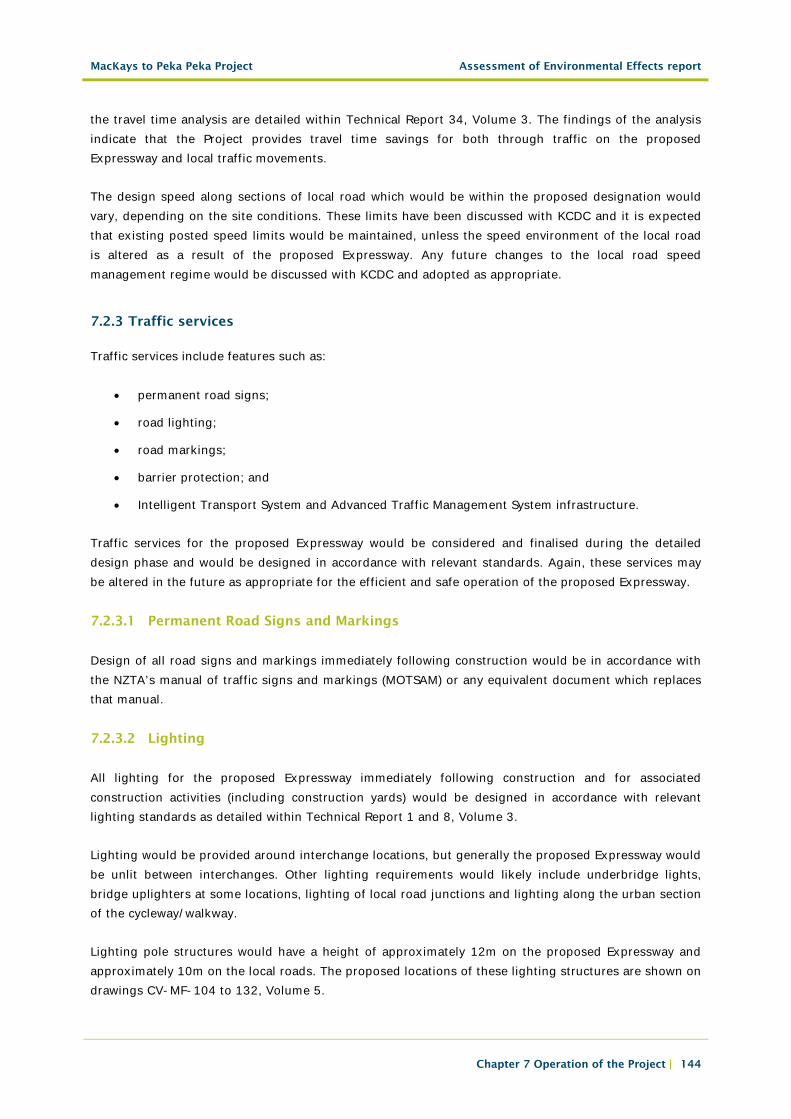
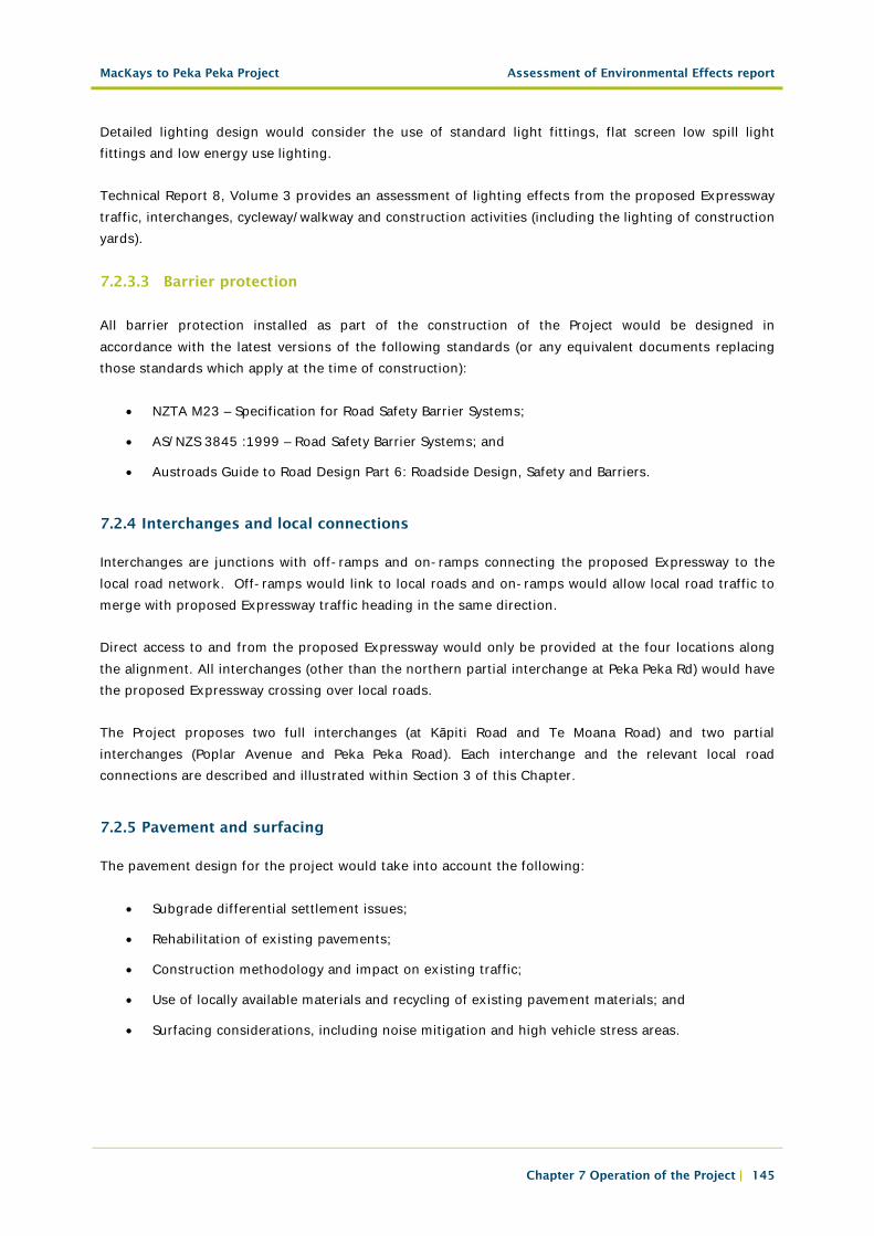
The form of the proposed Expressway immediately following construction is shown in detail within the Scheme Plans contained within Volume 5, which should be read in conjunction with this section. Figure 7.1 and 7.2 below provide a generalised cross section view of the proposed Expressway.
The proposed Expressway Project has been designed to the following general specifications along its length:
• 2 x 3.5m wide traffic lanes in each direction;
• Nearside shoulder width of 2.5m;
• Offside shoulder width of 1.0m;
• Nearside and offside shoulder widths will be carried over bridge structures;
• Nearside shoulder to be widened to 3m if adjacent to barriers;
MacKays to Peka Peka Project Assessment of Environmental Effects report
Chapter 7 Operation of the Project | 142
• A 4m wide median (edge line to edge line) at the southern end of the proposed Expressway, extending from the Project start point through to south of Raumati Road;
• A 6m wide median (edge line to edge line) from south of Raumati Road through to north of Mazengarb Road;
• A 4m wide median (edge line to edge line) from north of Mazengarb Road through to Peka Peka;
• A TL-4 wire rope median barrier51 generally, with concrete median barriers at some bridges over local roads (i.e. the locations where there are twin bridges);
• Where structures (i.e. a bridge pier or retaining wall face) cannot practicably be located outside the clear zone52, a TL-4 concrete barrier will be provided with 900mm minimum clearance behind the barrier;
• 9m wide trafficable clear zone, no steeper than 1V:4H at cut areas and low embankments;
• Steepened side slopes to 1V:3H with edge barriers, at higher embankments; and
• Additional edge barriers at locations with obstructions in the clear zone (e.g. drainage structures).
Figure 7.1: General Cross Section of the proposed Expressway through a Rural Area
51 Flexible barrier systems, such as wire rope barriers, are generally more forgiving than other types because most of the impact energy is dissipated by deflection of the barrier and lower impact forces are imposed on the vehicle and its occupants. Wire rope barriers approved for use on State highways have different deflection characteristics for a given National Cooperative Highway Research Program Report 350 (NCHRP Report 350) test level (in this case the wire rope will meet Test Level 4). The primary criterion for the approval of a barrier system is that it must have been successfully crash tested and the results evaluated in accordance with the Recommended Procedures for the Safety Performance of
Highway Features (NCHRP Report 350).
52 A clear zone is a recovery zone in which a driver may regain the control of an errant vehicle. The clear zone must be free from hazards or objects and traversable by a vehicle.
MacKays to Peka Peka Project Assessment of Environmental Effects report
Chapter 7 Operation of the Project | 143
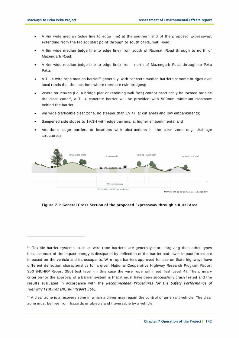
Figure 7.2: General Cross Section of the proposed Expressway through an Urban Area
b. Local Roads
Sections of new or reconstructed local road located within the proposed designation would have a cross section and geometry which complies with relevant design standards for local roads, as agreed with KCDC.
7.2.2 Traffic volumes and flow
7.2.2.1 Traffic Volumes
By 2026, it is predicted that over 25,000 vehicles per day would use one or more sections of the proposed Expressway (refer to Technical Report 34, Volume 3).
With the Project in place, the traffic flows on the existing SH1 are expected to reduce by approximately 35% to 55%. The current delays experienced at priority-controlled intersections such as Poplar Avenue, Raumati Road, Ihakara Street, and Otaihanga Road are predicted to reduce significantly.
The Assessment of Transport Effects (Technical Report 32, Volume 3) details how the Project is predicted to impact on the wider transport network.
7.2.2.2 Design Speed
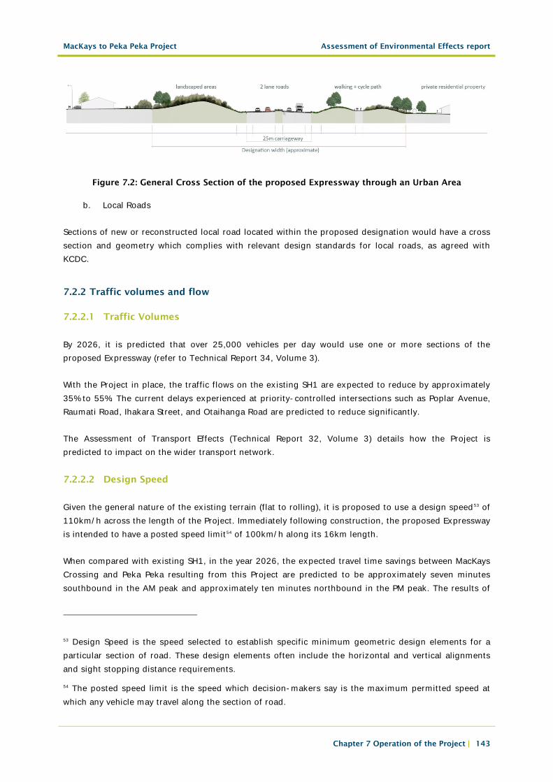
Given the general nature of the existing terrain (flat to rolling), it is proposed to use a design speed53 of 110km/h across the length of the Project. Immediately following construction, the proposed Expressway is intended to have a posted speed limit54 of 100km/h along its 16km length.
When compared with existing SH1, in the year 2026, the expected travel time savings between MacKays Crossing and Peka Peka resulting from this Project are predicted to be approximately seven minutes southbound in the AM peak and approximately ten minutes northbound in the PM peak. The results of
53 Design Speed is the speed selected to establish specific minimum geometric design elements for a particular section of road. These design elements often include the horizontal and vertical alignments and sight stopping distance requirements.
54 The posted speed limit is the speed which decision-makers say is the maximum permitted speed at which any vehicle may travel along the section of road.
MacKays to Peka Peka Project Assessment of Environmental Effects report
Chapter 7 Operation of the Project | 144
the travel time analysis are detailed within Technical Report 34, Volume 3. The findings of the analysis indicate that the Project provides travel time savings for both through traffic on the proposed Expressway and local traffic movements.
The design speed along sections of local road which would be within the proposed designation would vary, depending on the site conditions. These limits have been discussed with KCDC and it is expected that existing posted speed limits would be maintained, unless the speed environment of the local road is altered as a result of the proposed Expressway. Any future changes to the local road speed management regime would be discussed with KCDC and adopted as appropriate.
7.2.3 Traffic services
Traffic services include features such as:
• permanent road signs;
• road lighting;
• road markings;
• barrier protection; and
• Intelligent Transport System and Advanced Traffic Management System infrastructure.
Traffic services for the proposed Expressway would be considered and finalised during the detailed design phase and would be designed in accordance with relevant standards. Again, these services may be altered in the future as appropriate for the efficient and safe operation of the proposed Expressway.
7.2.3.1 Permanent Road Signs and Markings
Design of all road signs and markings immediately following construction would be in accordance with the NZTA’s manual of traffic signs and markings (MOTSAM) or any equivalent document which replaces that manual.
7.2.3.2 Lighting
All lighting for the proposed Expressway immediately following construction and for associated construction activities (including construction yards) would be designed in accordance with relevant lighting standards as detailed within Technical Report 1 and 8, Volume 3.
Lighting would be provided around interchange locations, but generally the proposed Expressway would be unlit between interchanges. Other lighting requirements would likely include underbridge lights, bridge uplighters at some locations, lighting of local road junctions and lighting along the urban section of the cycleway/walkway.
Lighting pole structures would have a height of approximately 12m on the proposed Expressway and approximately 10m on the local roads. The proposed locations of these lighting structures are shown on drawings CV-MF-104 to 132, Volume 5.
MacKays to Peka Peka Project Assessment of Environmental Effects report
Chapter 7 Operation of the Project | 145
Detailed lighting design would consider the use of standard light fittings, flat screen low spill light fittings and low energy use lighting.
Technical Report 8, Volume 3 provides an assessment of lighting effects from the proposed Expressway traffic, interchanges, cycleway/walkway and construction activities (including the lighting of construction yards).
7.2.3.3 Barrier protection
All barrier protection installed as part of the construction of the Project would be designed in accordance with the latest versions of the following standards (or any equivalent documents replacing those standards which apply at the time of construction):
• NZTA M23 – Specification for Road Safety Barrier Systems;
• AS/NZS 3845 :1999 – Road Safety Barrier Systems; and
• Austroads Guide to Road Design Part 6: Roadside Design, Safety and Barriers.
7.2.4 Interchanges and local connections
Interchanges are junctions with off-ramps and on-ramps connecting the proposed Expressway to the local road network. Off-ramps would link to local roads and on-ramps would allow local road traffic to merge with proposed Expressway traffic heading in the same direction.
Direct access to and from the proposed Expressway would only be provided at the four locations along the alignment. All interchanges (other than the northern partial interchange at Peka Peka Rd) would have the proposed Expressway crossing over local roads.
The Project proposes two full interchanges (at Kāpiti Road and Te Moana Road) and two partial interchanges (Poplar Avenue and Peka Peka Road). Each interchange and the relevant local road connections are described and illustrated within Section 3 of this Chapter.
7.2.5 Pavement and surfacing
The pavement design for the project would take into account the following:
• Subgrade differential settlement issues;
• Rehabilitation of existing pavements;
• Construction methodology and impact on existing traffic;
• Use of locally available materials and recycling of existing pavement materials; and
• Surfacing considerations, including noise mitigation and high vehicle stress areas.
MacKays to Peka Peka Project Assessment of Environmental Effects report
Chapter 7 Operation of the Project | 146
7.2.5.1 Proposed Expressway Pavement
The general pavement philosophy for the construction of the Project is to use granular subbase and base layers with additives to improve the strength and durability of the pavement. This approach provides a flexible pavement that is suitable for the environment which the proposed Expressway would pass through, and allows for simple rehabilitation if this is required in the future.
7.2.5.2 Proposed Expressway Surfacing
The proposed Expressway would pass through parts of the Raumati, Paraparaumu and Waikanae residential areas. In these areas, the noise mitigation measures provided as part of the construction of the Project would likely incorporate the use of low traffic noise surfacing known as Open Graded Porous Asphalt (OGPA). This form of road surfacing is proposed to be used in the construction of the Project from north of Poplar Avenue to just north of the Te Moana interchange and then for a 1km section adjacent to existing houses on End Farm Road (approximately 2km south of Peka Peka Road). A further 1km section of OGPA is proposed near Peka Peka Road.
Chip seal is proposed to be used in the construction of the Project south of Poplar Avenue and from north of the houses on End Farm Road.
Stone Mastic Asphalt (SMA) is proposed for the construction of the Project in high stress (braking/turning) areas like on the on- and off-ramps where they connect to the local road.
7.2.5.3 Local Road Surfacing
It is proposed that all other locations will have chip seal to match the existing surfacing. SMA is proposed for the construction of high stress areas including roundabouts and approaches. OGPA would be used in construction works on Te Moana Road to mitigate noise effects (as detailed in Technical Report 15, Volume 5).
7.2.5.4 Cycleway/Walkway Surfacing
A fine chip seal is proposed to be used for the construction of the section of the cycleway/walkway from Poplar Avenue to Otaihanga Road and at the approaches to all local road junctions. An aggregate known as Kāpiti Blue would be used for the construction of the part of the cycleway/walkway north of Otaihanga Road.
7.2.6 Bridges and other key structures
A general description of the bridges and other key structures proposed for the Project are described below.
MacKays to Peka Peka Project Assessment of Environmental Effects report
Chapter 7 Operation of the Project | 147
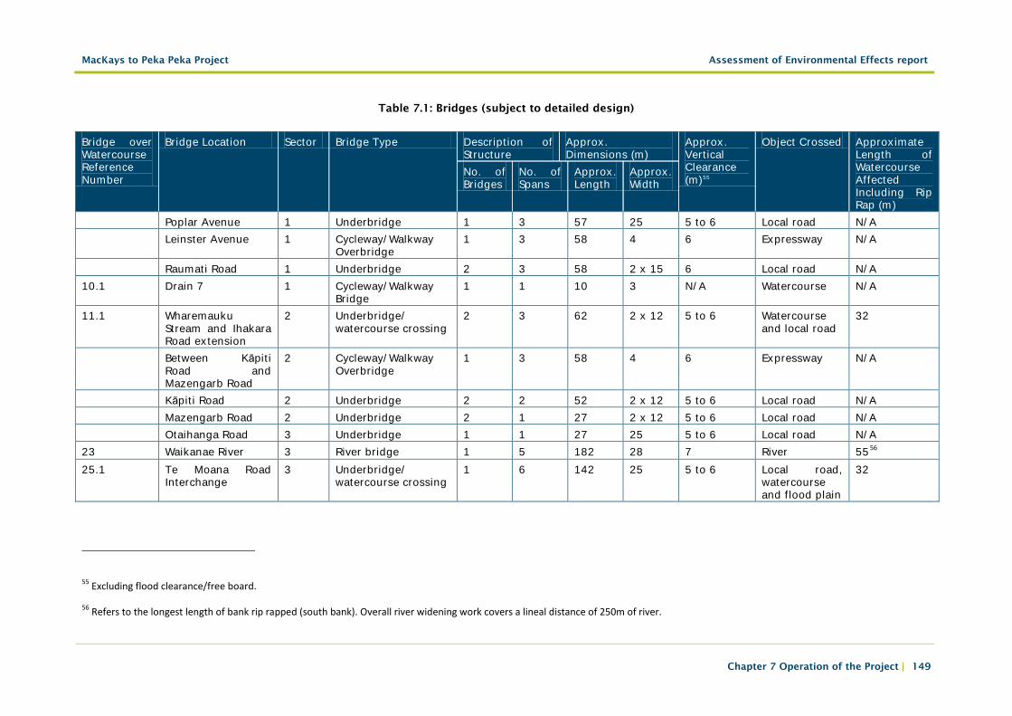
7.2.6.1 Bridges
There are 18 principal bridge structures proposed as part of the Project. These are summarised within Table 7.1. Further detail about the location and form of all the bridges is also contained within Technical Report 1, Volume 3 and Bridge Scheme Plan drawings ST-BR-150 to 970, Volume 5.
Bridges needed as part of the Project are required to cross over one or more of the following obstacles:
• access roads and local roads;
• watercourses; and
• the proposed Expressway.
7.2.6.2 Overbridges
Overbridges are those bridge structures that would be required to carry local roads and/or the cycleway/walkway over the proposed Expressway. Subject to detailed design, across the Project, these structures would generally have the following layout:
• A width of 15 to 17m; and
• A vertical clearance of 6m.
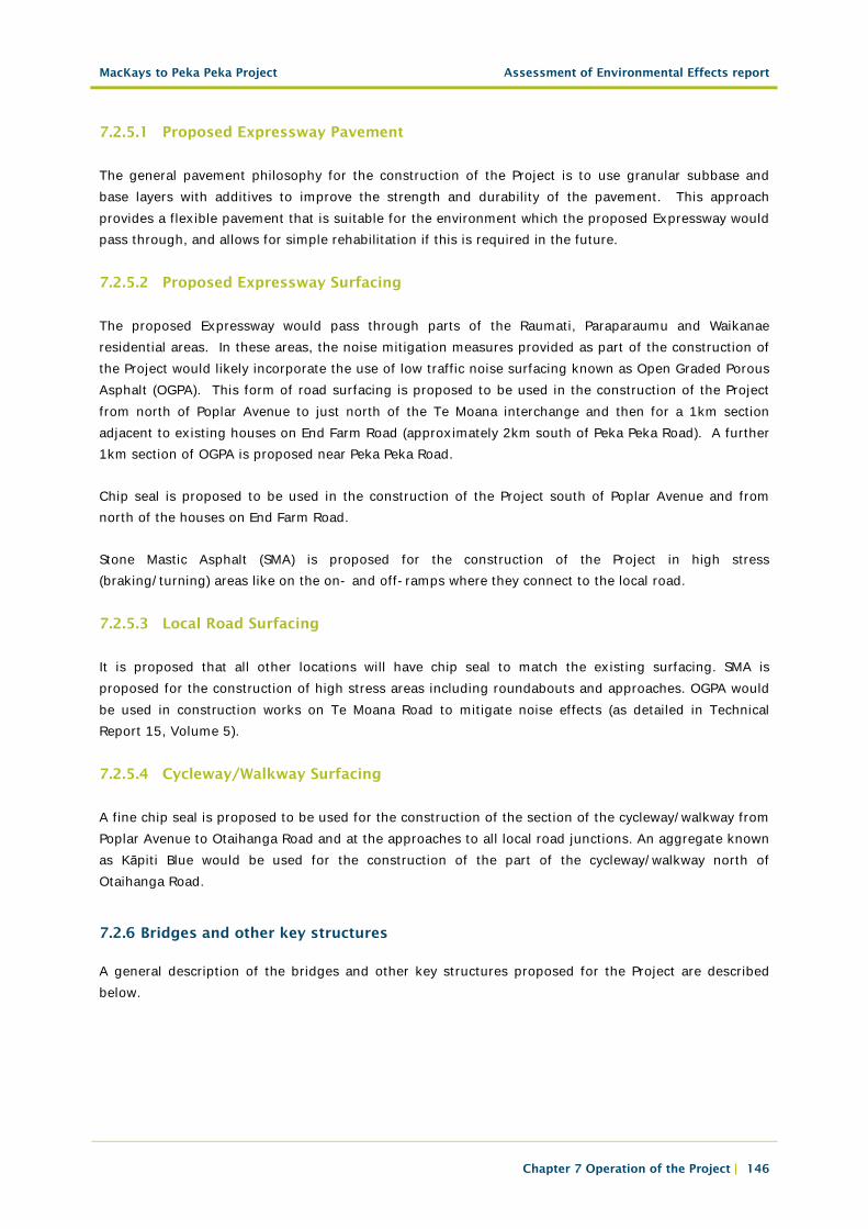
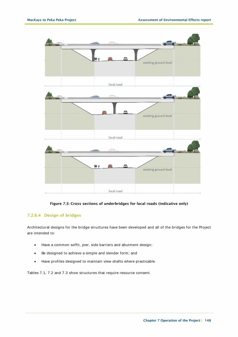
7.2.6.3 Underbridges
• Underbridges are those bridge structures that would be required to carry the proposed Expressway over local roads, the cycleway/walkway and watercourses. Subject to detailed design, across the Project, these structures would generally have the following layout:
• A width between 12m to 15m for twin bridges and approximately 12m to 28m for single bridges; and
• A vertical clearance ranging between 5m and 6m.
MacKays to Peka Peka Project Assessment of Environmental Effects report
Chapter 7 Operation of the Project | 148
Figure 7.3: Cross sections of underbridges for local roads (indicative only)
7.2.6.4 Design of bridges
Architectural designs for the bridge structures have been developed and all of the bridges for the Project are intended to:
• Have a common soffit, pier, side barriers and abutment design;
• Be designed to achieve a simple and slender form; and
• Have profiles designed to maintain view shafts where practicable.
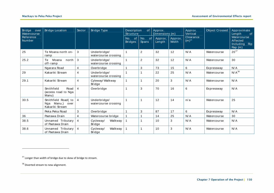
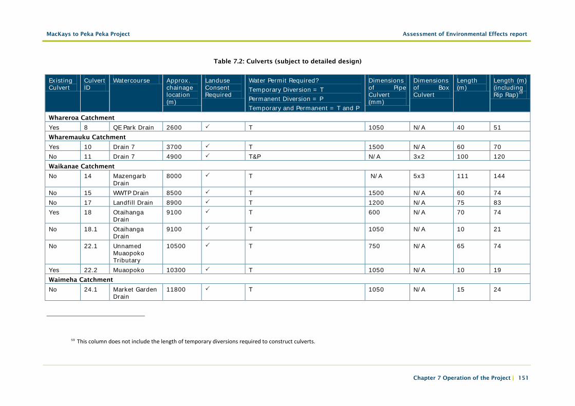
Tables 7.1, 7.2 and 7.3 show structures that require resource consent.
MacKays to Peka Peka Project Assessment of Environmental Effects report
Chapter 7 Operation of the Project | 149
Table 7.1: Bridges (subject to detailed design)
Bridge over Watercourse Reference Number
Bridge Location Sector Bridge Type Description of Structure
Approx. Dimensions (m)
Approx. Vertical Clearance (m)55
Object Crossed Approximate Length of Watercourse Affected Including Rip Rap (m)
No. of Bridges
No. of Spans
Approx. Length
Approx. Width
Poplar Avenue 1 Underbridge 1 3 57 25 5 to 6 Local road N/A Leinster Avenue 1 Cycleway/Walkway
Overbridge 1 3 58 4 6 Expressway N/A
Raumati Road 1 Underbridge 2 3 58 2 x 15 6 Local road N/A 10.1 Drain 7 1 Cycleway/Walkway
Bridge 1 1 10 3 N/A Watercourse N/A
11.1 Wharemauku Stream and Ihakara Road extension
2 Underbridge/ watercourse crossing
2 3 62 2 x 12 5 to 6 Watercourse and local road
32
Between Kāpiti Road and Mazengarb Road
2 Cycleway/Walkway Overbridge
1 3 58 4 6 Expressway N/A
Kāpiti Road 2 Underbridge 2 2 52 2 x 12 5 to 6 Local road N/A Mazengarb Road 2 Underbridge 2 1 27 2 x 12 5 to 6 Local road N/A Otaihanga Road 3 Underbridge 1 1 27 25 5 to 6 Local road N/A 23 Waikanae River 3 River bridge 1 5 182 28 7 River 5556 25.1 Te Moana Road
Interchange 3 Underbridge/
watercourse crossing 1 6 142 25 5 to 6 Local road,
watercourse and flood plain
32
55 Excluding flood clearance/free board.
56 Refers to the longest length of bank rip rapped (south bank). Overall river widening work covers a lineal distance of 250m of river.
MacKays to Peka Peka Project Assessment of Environmental Effects report
Chapter 7 Operation of the Project | 150
Bridge over Watercourse Reference Number
Bridge Location Sector Bridge Type Description of Structure
Approx. Dimensions (m)
Approx. Vertical Clearance (m)55
Object Crossed Approximate Length of Watercourse Affected Including Rip Rap (m)
No. of Bridges
No. of Spans
Approx. Length
Approx. Width
25 Te Moana north on-ramp
3 Underbridge/ watercourse crossing
1 2 32 12 N/A Watercourse 2057
25.2 Te Moana north off-ramp
3 Underbridge/ watercourse crossing
1 2 32 12 N/A Watercourse 30
Ngarara Road 4 Overbridge 1 3 73 15 6 Expressway N/A 29 Kakariki Stream 4 Underbridge/
watercourse crossing 1 1 22 25 N/A Watercourse N/A58
29.1 Kakariki Stream 4 Cyleway/Walkway Bridge
1 1 20 3 N/A Watercourse N/A
Smithfield Road (access road to Nga Manu)
4 Overbridge 1 3 70 16 6 Expressway N/A
30.5 Smithfield Road( to Nga Manu,) over Kakariki Stream
4 Underbridge/ watercourse crossing
1 1 12 14 n/a Watercourse 25
Peka Peka Road 3 Overbridge 1 3 87 17 6 Expressway N/A 36 Paetawa Drain 4 Watercourse bridge 1 1 14 25 N/A Watercourse 30 38.5 Unnamed Tributary
of Paetawa Drain 4 Cycleway/ Walkway
Bridge 1 1 10 3 N/A Watercourse N/A
38.6 Unnamed Tributary of Paetawa Drain
4 Cycleway/ Walkway Bridge
1 1 10 3 N/A Watercourse N/A
57 Longer than width of bridge due to skew of bridge to stream.
58 Diverted stream to new alignment.
MacKays to Peka Peka Project Assessment of Environmental Effects report
Chapter 7 Operation of the Project | 151
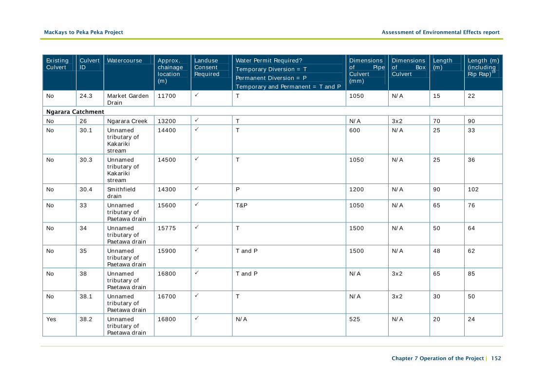
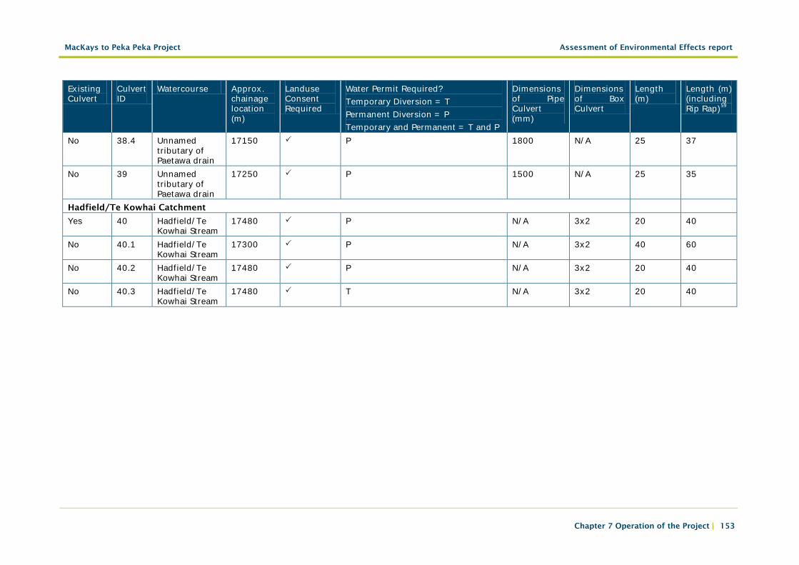
Table 7.2: Culverts (subject to detailed design)
Existing Culvert
Culvert ID
Watercourse Approx. chainage location (m)
Landuse Consent Required
Water Permit Required? Temporary Diversion = T Permanent Diversion = P Temporary and Permanent = T and P
Dimensions of Pipe Culvert (mm)
Dimensions of Box Culvert
Length (m)
Length (m) (including Rip Rap)59
Whareroa Catchment
Yes 8 QE Park Drain 2600 T 1050 N/A 40 51 Wharemauku Catchment
Yes 10 Drain 7 3700 T 1500 N/A 60 70 No 11 Drain 7 4900 T&P N/A 3x2 100 120 Waikanae Catchment
No 14 Mazengarb Drain
8000 T N/A 5x3 111 144
No 15 WWTP Drain 8500 T 1500 N/A 60 74 No 17 Landfill Drain 8900 T 1200 N/A 75 83 Yes 18 Otaihanga
Drain 9100 T 600 N/A 70 74
No 18.1 Otaihanga Drain
9100 T 1050 N/A 10 21
No 22.1 Unnamed Muaopoko Tributary
10500 T 750 N/A 65 74
Yes 22.2 Muaopoko 10300 T 1050 N/A 10 19 Waimeha Catchment
No 24.1 Market Garden Drain
11800 T 1050 N/A 15 24
59 This column does not include the length of temporary diversions required to construct culverts.
MacKays to Peka Peka Project Assessment of Environmental Effects report
Chapter 7 Operation of the Project | 152
Existing Culvert
Culvert ID
Watercourse Approx. chainage location (m)
Landuse Consent Required
Water Permit Required? Temporary Diversion = T Permanent Diversion = P Temporary and Permanent = T and P
Dimensions of Pipe Culvert (mm)
Dimensions of Box Culvert
Length (m)
Length (m) (including Rip Rap)59
No 24.3 Market Garden Drain
11700 T 1050 N/A 15 22
Ngarara Catchment
No 26 Ngarara Creek 13200 T N/A 3x2 70 90 No 30.1 Unnamed
tributary of Kakariki stream
14400 T 600 N/A 25 33
No 30.3 Unnamed tributary of Kakariki stream
14500 T 1050 N/A 25 36
No 30.4 Smithfield drain
14300 P 1200 N/A 90 102
No 33 Unnamed tributary of Paetawa drain
15600 T&P 1050 N/A 65 76
No 34 Unnamed tributary of Paetawa drain
15775 T 1500 N/A 50 64
No 35 Unnamed tributary of Paetawa drain
15900 T and P 1500 N/A 48 62
No 38 Unnamed tributary of Paetawa drain
16800 T and P N/A 3x2 65 85
No 38.1 Unnamed tributary of Paetawa drain
16700 T N/A 3x2 30 50
Yes 38.2 Unnamed tributary of Paetawa drain
16800 N/A 525 N/A 20 24
MacKays to Peka Peka Project Assessment of Environmental Effects report
Chapter 7 Operation of the Project | 153
Existing Culvert
Culvert ID
Watercourse Approx. chainage location (m)
Landuse Consent Required
Water Permit Required? Temporary Diversion = T Permanent Diversion = P Temporary and Permanent = T and P
Dimensions of Pipe Culvert (mm)
Dimensions of Box Culvert
Length (m)
Length (m) (including Rip Rap)59
No 38.4 Unnamed tributary of Paetawa drain
17150 P 1800 N/A 25 37
No 39 Unnamed tributary of Paetawa drain
17250 P 1500 N/A 25 35
Hadfield/Te Kowhai Catchment
Yes 40 Hadfield/Te Kowhai Stream
17480 P N/A 3x2 20 40
No 40.1 Hadfield/Te Kowhai Stream
17300 P N/A 3x2 40 60
No 40.2 Hadfield/Te Kowhai Stream
17480 P N/A 3x2 20 40
No 40.3 Hadfield/Te Kowhai Stream
17480 T N/A 3x2 20 40
MacKays to Peka Peka Project Assessment of Environmental Effects report
Chapter 7 Operation of the Project | 154
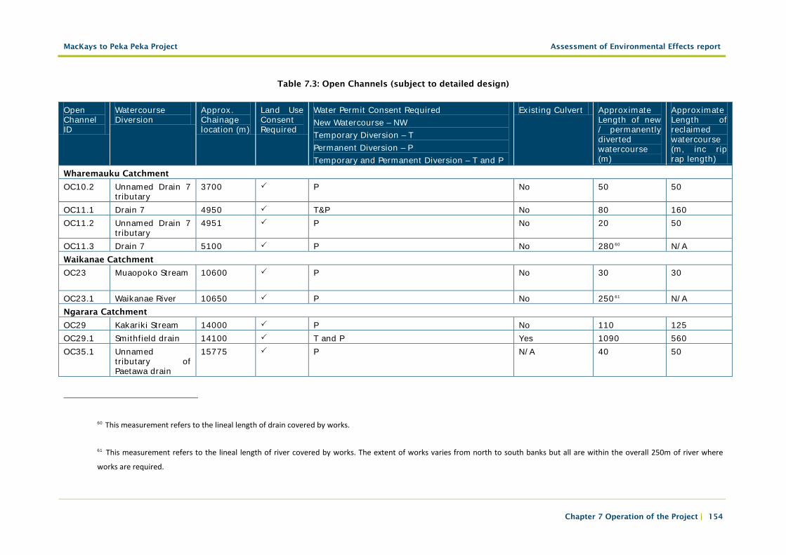
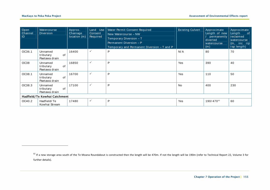
Table 7.3: Open Channels (subject to detailed design)
Open Channel ID
Watercourse Diversion
Approx. Chainage location (m)
Land Use Consent Required
Water Permit Consent Required New Watercourse – NW Temporary Diversion – T Permanent Diversion – P Temporary and Permanent Diversion – T and P
Existing Culvert Approximate Length of new / permanently diverted watercourse (m)
Approximate Length of reclaimed watercourse (m, inc rip rap length)
Wharemauku Catchment
OC10.2 Unnamed Drain 7 tributary
3700 P No 50 50
OC11.1 Drain 7 4950 T&P No 80 160 OC11.2 Unnamed Drain 7
tributary 4951 P No 20 50
OC11.3 Drain 7 5100 P No 28060 N/A Waikanae Catchment
OC23 Muaopoko Stream
10600 P No 30 30
OC23.1 Waikanae River 10650 P No 25061 N/A Ngarara Catchment
OC29 Kakariki Stream 14000 P No 110 125 OC29.1 Smithfield drain 14100 T and P Yes 1090 560 OC35.1 Unnamed
tributary of Paetawa drain
15775 P N/A 40 50
60 This measurement refers to the lineal length of drain covered by works.
61 This measurement refers to the lineal length of river covered by works. The extent of works varies from north to south banks but all are within the overall 250m of river where
works are required.
MacKays to Peka Peka Project Assessment of Environmental Effects report
Chapter 7 Operation of the Project | 155
Open Channel ID
Watercourse Diversion
Approx. Chainage location (m)
Land Use Consent Required
Water Permit Consent Required New Watercourse – NW Temporary Diversion – T Permanent Diversion – P Temporary and Permanent Diversion – T and P
Existing Culvert Approximate Length of new / permanently diverted watercourse (m)
Approximate Length of reclaimed watercourse (m, inc rip rap length)
OC36.1 Unnamed tributary of Paetawa drain
16400 P N/A 80 70
OC38 Unnamed tributary of Paetawa drain
16850 P Yes 390 40
OC38.1 Unnamed tributary of Paetawa drain
16700 P Yes 110 50
OC38.3 Unnamed tributary of Paetawa drain
17100 P No 400 230
Hadfield/Te Kowhai Catchment
OC40.2 Hadfield/Te Kowhai Stream
17480 P Yes 190/47062 60
62 If a new storage area south of the Te Moana Roundabout is constructed then the length will be 470m. If not the length will be 190m (refer to Technical Report 22, Volume 3 for
further details).
MacKays to Peka Peka Project Assessment of Environmental Effects report
Chapter 7 Operation of the Project | 156
7.2.6.5 Retaining walls
Mechanically Stabilised Earth (MSE) walls would generally be used in the areas of fill and Bore Piled (BP) walls would generally be used in the areas of cut.
Retaining walls would generally be used in the following situations:
• At the abutments of some bridges; and
• Around the ramps of some interchanges.
All retaining walls would be designed in accordance with the Transit New Zealand Bridge Manual.
Further design detail on retaining walls can be found within Technical Report 1, Volume 3.
7.2.6.6 Bridge abutments
Bridge abutments across the Project would either be spill through63 with a 2H:1V slope, or vertical. Both abutment types would be reinforced with geogrid.
Further structural design detail on bridge abutments can be found within Technical Report 1, Volume 3.
The visual appearance and materials used on the face of abutments would be consistent with the ULDF (Technical Report 5, Volume 3).
7.2.7 Noise attenuation
The guiding approach for the acoustic design is to address the adverse effects of road-traffic noise on people.
Noise attenuation design would be carried out in accordance with:
• NZS 6806:2010 Acoustics – Road Traffic Noise – New and Altered Roads
Noise attenuation through design could be achieved through a number of measures, some of which may be required in combination with others:
• Low-noise generating road surfacing, (e.g. OGPA);
• Noise barriers (including noise bunds64 and noise walls);
63 Spill through bridges refer to an Expressway bridge with a gap between the two bridge decks to allow natural light to illuminate the local road below. Refer to the ULDF, Technical Report 5, Volume 3 for illustrations.
MacKays to Peka Peka Project Assessment of Environmental Effects report
Chapter 7 Operation of the Project | 157
• Property boundary noise fences; and
• Where it would not be practicable to reduce external noise to the levels set out in NZS6806, acoustic insulation for the internal habitable spaces of buildings where noise sensitive activities are undertaken.
Details of likely noise attenuation measures are illustrated in the Scheme Plans within Volume 5. The assessment of noise effects and mitigation options are summarised in Part G, Chapter 19 of this AEE report and detailed within Technical Report 15, Volume 3.
7.2.8 Surface drainage, stormwater treatment and flood management
a. Watercourses
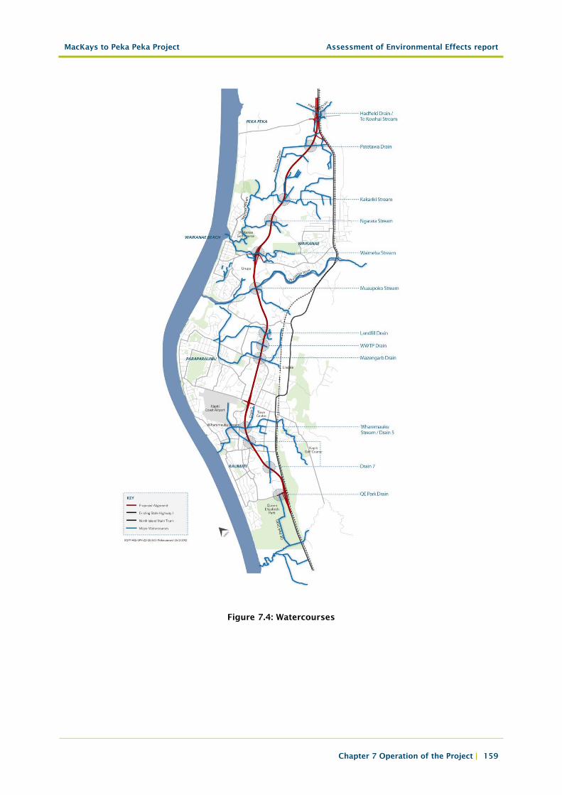
The proposed Expressway would cross the following watercourses along the route (from South to North):
• Wharemauku Stream and tributary drains;
• Mazengarb Drain;
• Wastewater Treatment Plant Drain;
• Landfill Drain;
• Muaupoko Stream;
• Waikanae River;
• Waimeha Stream;
• Ngarara Creek;
• Kakariki Stream (adjacent Ngā Manu Wildlife Reserve);
• Smithfield Drain;
• Paetawa Drain;
• Hadfield Drain/Te Kowhai Stream;
• Wetland areas (of varying sizes and environmental significance);
• Land drains & other smaller watercourses;
• Local KCDC drainage networks; and
• Floodplains and other flood storage areas and flow paths (including associated infrastructure such as stopbanks) associated with the above.
64 Bunds are mounds of earth. In addition to shielding noise, a noise bund can be landscaped to enhance amenity.
MacKays to Peka Peka Project Assessment of Environmental Effects report
Chapter 7 Operation of the Project | 158
b. Flood Management
Significant parts of the Project would traverse low-lying land that is prone to flooding. A key design principle is to achieve hydraulic neutrality; in other words, not to increase flooding through loss of floodplain storage or increased stormwater discharges. In achieving this outcome, the Project must recognise existing KCDC/GWRC flood management strategies.
The Project has also been designed to accommodate the passing of floodwater (via bridges and culverts) across the corridor. It would also be necessary in some locations to create additional flood storage areas to compensate for loss of existing floodplain storage as a result of being filled in by the proposed Expressway. These storage areas would generally be created in the form of low-lying areas of land, planted out with native vegetation or, if suitable, reinstated as pasture. To mitigate the increased peak runoff from the proposed Expressway pavement, attenuation would be provided to hold back stormwater, avoiding flooding downstream. This would be provided by constructing lengths of deep swales and several new wetlands.
MacKays to Peka Peka Project Assessment of Environmental Effects report
Chapter 7 Operation of the Project | 159
Figure 7.4: Watercourses
MacKays to Peka Peka Project Assessment of Environmental Effects report
Chapter 7 Operation of the Project | 160
c. Culverts and Bridges65
Existing watercourses would cross under the proposed Expressway either by way of a culvert or a bridge, generally depending on the size of the watercourse. The locations of proposed bridges are described in Table 7.1 above and the locations of proposed culverts are described in Technical Report 22, Volume 3. Provision will be made for fish passage where necessary, in accordance with GWRC guidelines.
c. Surface drainage
Runoff from the proposed Expressway would generally be allowed to flow down the grassed/planted slopes adjoining the carriageway and be collected in a swale at the toe of the slope. In some locations space would be constrained or barriers/walls would be along the edge of the proposed Expressway. In these locations sumps would collect the runoff and drain it to either pipes or swales.
Bridge deck drainage would generally be achieved by collecting runoff from the bridge deck and discharging into the adjacent drainage system at the ends of the bridge.
Runoff from the cycleway/walkway would flow directly to a watercourse untreated, unless it happens to be adjacent to a road swale or wetland.
For further details on the drainage methodology refer to Technical Report 22, Volume 3.
d. Stormwater treatment
Treatment of runoff from the proposed Expressway has been designed in accordance with NZTA’s Stormwater Treatment Standard for State highway Infrastructure.
Treatment would be provided through a combination of deep swales along the edge of the proposed Expressway and/or wetlands. The swales would either be planted with native wet tolerant species in areas of peat or grassed in areas of sand. Where it is more topographically or ecologically appropriate, wetlands would be used. These will treat the runoff for gross debris, suspended sediment, heavy metals
65 There are some differences in the lengths of the watercourse that will be culverted and those that will also be diverted between the Assessment of Hydrology and Stormwater Effects (Technical Report 22, Volume 3) and the Ecological Impact Assessment (Technical Report 26, Volume 3). This is a consequence of the different types of watercourses present across the Project. The figures presented in Technical Report 22 describe the proposed works relating to watercourses in general without accounting for the various ecological values of each, while the figures presented in Technical Report 26 however, does take this into account. The ecological figures relate solely to whether the proposed works are within perennial or intermittent watercourses. Ephemeral watercourses are not included in the ecological figures as these typically comprise of farm drains and existing roadside depressions or swales that may carry runoff during storms but which have little to no aquatic habitat value and are largely stormwater conveyance systems. This assessment is based on our knowledge of each of these waterbodies gained from site visits and research into background information.
MacKays to Peka Peka Project Assessment of Environmental Effects report
Chapter 7 Operation of the Project | 161
and hydrocarbons. All stormwater treatment systems would include safe access for maintenance. Typically, a 5m maintenance margin would be provided around wetlands with excavator access ramps also provided for cleaning out of the sediment forebay.
e. Wetlands
Wetlands throughout the Project area would take the form of either:
• Constructed stormwater wetlands specifically for the purpose of stormwater treatment and attenuation;
• Existing or constructed “natural” wetlands which in some instances become inundated during times of flood as they currently do; or
• New wetland areas created for ecological offsetting purposes.
All three types of wetlands have different functions and characteristics, as described within Technical Reports 22 and 26, Volume 3.
Some of the existing wet depressions in the land which would have once been wetlands would be restored to assist with stormwater management where they would be located in proximity to the proposed Expressway. “Natural” wetlands with high ecological value would not be utilised for stormwater treatment purposes. Where additional wetlands are required, they would be designed to replicate, as close as possible, the hydrological function/regime of a natural wetland.
7.2.9 Cycleway/walkway and bridleway
a. Cycleway/walkway
A shared cycleway/walkway would be provided for the length of the proposed Expressway, separated from the edge of the proposed Expressway shoulder. The separation distance between the cycleway/walkway and the proposed Expressway would vary in order to take advantage of landforms and landscape features and to avoid obstacles such as wetland areas.
The cycleway/walkway would generally be located on the west side of the proposed Expressway alignment; however, between Otaihanga Road (chainage 9200m) and Ngarara Road (chainage 13550m), where space on the western side is limited, it would be located on the eastern side of the proposed Expressway.
With a width of approximately 3m and a centreline marking, the cycleway/walkway would allow for two way cycle and pedestrian traffic. The 3m width of the cycleway/walkway would be appropriately formed, with a sealed surface in the urban areas and looser surface in rural areas.
Timber 3m wide cycleway/walkway overbridges may be used to cross a number of small local watercourses and, similarly, boardwalks are proposed to cross over some wetland areas.
Where practicable, the cycleway/walkway would connect at grade with local roads and existing cycle/walkway networks.

MacKays to Peka Peka Project Assessment of Environmental Effects report
Chapter 7 Operation of the Project | 162
Two cycleway/walkway overbridges are proposed as an east/west connection across the proposed Expressway. One bridge is proposed at Leinster Avenue and the other is proposed between Kāpiti Road and Mazengarb Road. These bridges would generally be 4m wide with an overall bridge length of 58m. A vertical clearance of approximately 6m would be provided.
b. Bridleway
Alongside sections of the formed cycleway/walkway, an additional 1m of land would be levelled for use as a bridleway (refer to Technical Report 5, Volume 3 for details).
Unlike the cycleway/walkway, the proposed Bridleway would not form a continuous pathway and would be limited to some rural sections of the proposed designation.
7.2.10 Urban design and landscaping
a. Urban design considerations
Urban design considerations for the Project include:
• Road alignment;
• Interchange location, type and design;
• Earthworks and retaining walls;
• Bridges/underpasses placement and design;
• Noise barriers type (bund/wall), height and design;
• Pedestrian and cycle networks;
• Stormwater ponds and swales;
• Highway furniture (side and median barriers, lighting, signage); and
• Landscape treatment and planting.
Further detail on urban design considerations are provided within the ULDF, Technical Report 5, Volume 3.
b. Landscaping and visual design
Landscaping associated with the Project aims to achieve:
• Visual mitigation, visual amenity and maintenance of landscape character;
• Ecological mitigation;
• Buffering; and
• Assistance with stormwater treatment.
MacKays to Peka Peka Project Assessment of Environmental Effects report
Chapter 7 Operation of the Project | 163
Planting would include hydroseeding and planting adjacent to the proposed Expressway and cycleway/walkway, interchanges, Expressway median, and wider proposed Expressway corridor as required, stormwater swales, wetlands, riparian margins, and flood storage areas as required.
Further details on landscaping and visual design are provided within Technical Report 7, Volume 3.
7.3 Sector specific project description
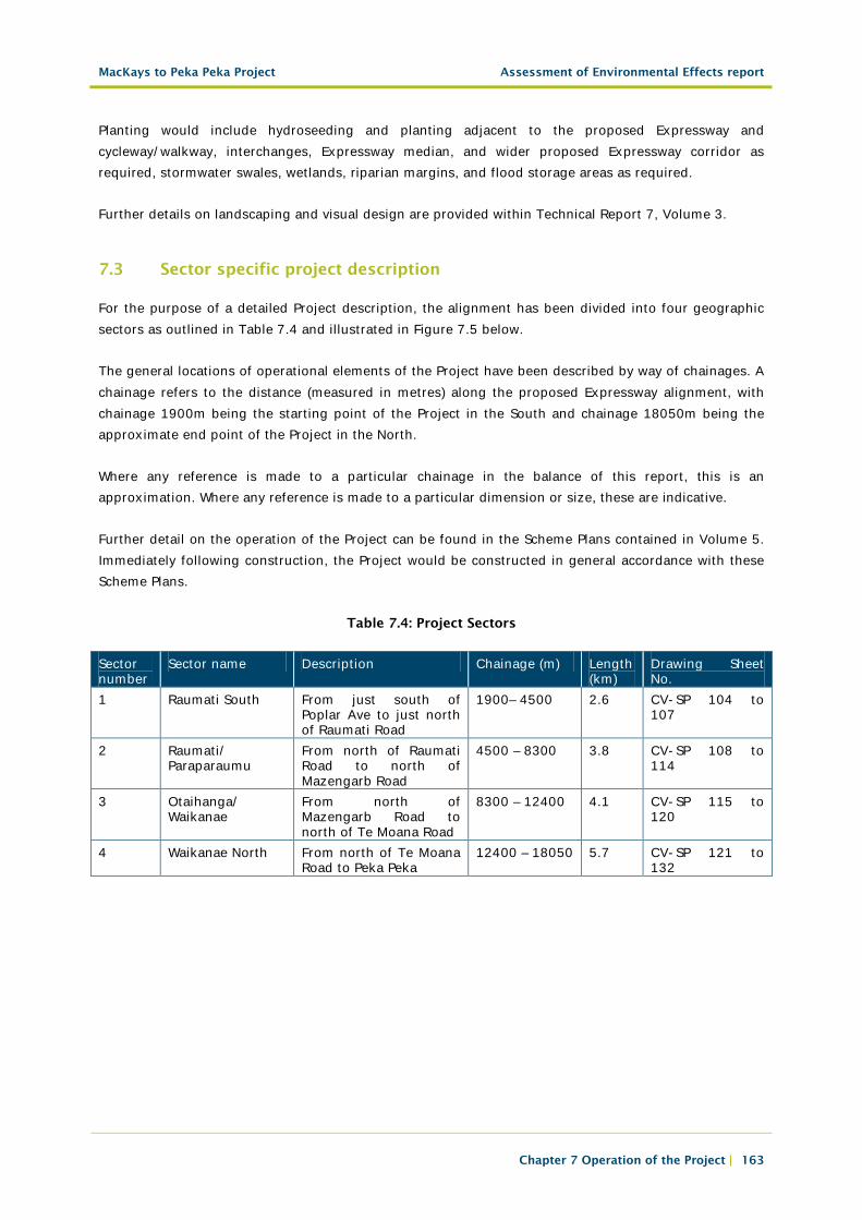
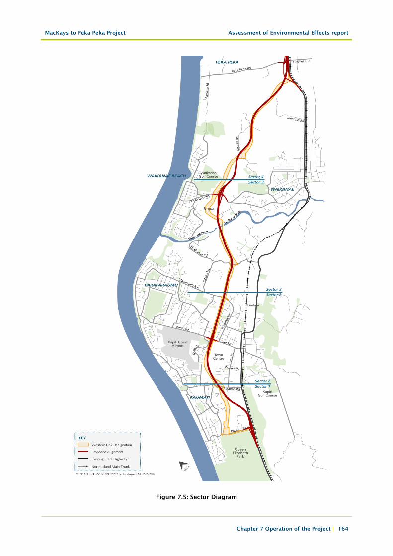
For the purpose of a detailed Project description, the alignment has been divided into four geographic sectors as outlined in Table 7.4 and illustrated in Figure 7.5 below.
The general locations of operational elements of the Project have been described by way of chainages. A chainage refers to the distance (measured in metres) along the proposed Expressway alignment, with chainage 1900m being the starting point of the Project in the South and chainage 18050m being the approximate end point of the Project in the North.
Where any reference is made to a particular chainage in the balance of this report, this is an approximation. Where any reference is made to a particular dimension or size, these are indicative.
Further detail on the operation of the Project can be found in the Scheme Plans contained in Volume 5. Immediately following construction, the Project would be constructed in general accordance with these Scheme Plans.
Table 7.4: Project Sectors
Sector number
Sector name Description Chainage (m) Length (km)
Drawing Sheet No.
1 Raumati South From just south of Poplar Ave to just north of Raumati Road
1900– 4500 2.6 CV-SP 104 to 107
2 Raumati/ Paraparaumu
From north of Raumati Road to north of Mazengarb Road
4500 – 8300 3.8 CV-SP 108 to 114
3 Otaihanga/ Waikanae
From north of Mazengarb Road to north of Te Moana Road
8300 – 12400 4.1 CV-SP 115 to 120
4 Waikanae North From north of Te Moana Road to Peka Peka
12400 – 18050 5.7 CV-SP 121 to 132
MacKays to Peka Peka Project Assessment of Environmental Effects report
Chapter 7 Operation of the Project | 164
Figure 7.5: Sector Diagram
MacKays to Peka Peka Project Assessment of Environmental Effects report
Chapter 7 Operation of the Project | 165
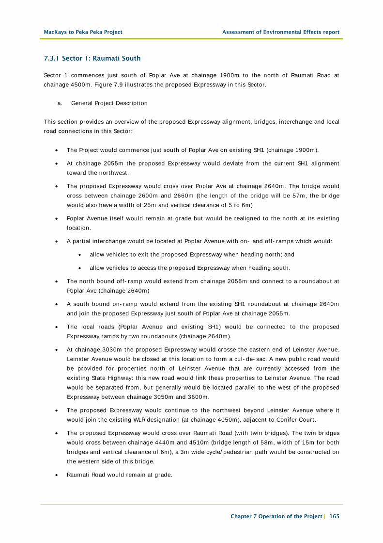
7.3.1 Sector 1: Raumati South
Sector 1 commences just south of Poplar Ave at chainage 1900m to the north of Raumati Road at chainage 4500m. Figure 7.9 illustrates the proposed Expressway in this Sector.
a. General Project Description
This section provides an overview of the proposed Expressway alignment, bridges, interchange and local road connections in this Sector:
• The Project would commence just south of Poplar Ave on existing SH1 (chainage 1900m).
• At chainage 2055m the proposed Expressway would deviate from the current SH1 alignment toward the northwest.
• The proposed Expressway would cross over Poplar Ave at chainage 2640m. The bridge would cross between chainage 2600m and 2660m (the length of the bridge will be 57m, the bridge would also have a width of 25m and vertical clearance of 5 to 6m)
• Poplar Avenue itself would remain at grade but would be realigned to the north at its existing location.
• A partial interchange would be located at Poplar Avenue with on- and off-ramps which would:
• allow vehicles to exit the proposed Expressway when heading north; and
• allow vehicles to access the proposed Expressway when heading south.
• The north bound off-ramp would extend from chainage 2055m and connect to a roundabout at Poplar Ave (chainage 2640m)
• A south bound on-ramp would extend from the existing SH1 roundabout at chainage 2640m and join the proposed Expressway just south of Poplar Ave at chainage 2055m.
• The local roads (Poplar Avenue and existing SH1) would be connected to the proposed Expressway ramps by two roundabouts (chainage 2640m).
• At chainage 3030m the proposed Expressway would crosse the eastern end of Leinster Avenue. Leinster Avenue would be closed at this location to form a cul-de-sac. A new public road would be provided for properties north of Leinster Avenue that are currently accessed from the existing State Highway: this new road would link these properties to Leinster Avenue. The road would be separated from, but generally would be located parallel to the west of the proposed Expressway between chainage 3050m and 3600m.
• The proposed Expressway would continue to the northwest beyond Leinster Avenue where it would join the existing WLR designation (at chainage 4050m), adjacent to Conifer Court.
• The proposed Expressway would cross over Raumati Road (with twin bridges). The twin bridges would cross between chainage 4440m and 4510m (bridge length of 58m, width of 15m for both bridges and vertical clearance of 6m), a 3m wide cycle/pedestrian path would be constructed on the western side of this bridge.
• Raumati Road would remain at grade.
MacKays to Peka Peka Project Assessment of Environmental Effects report
Chapter 7 Operation of the Project | 166
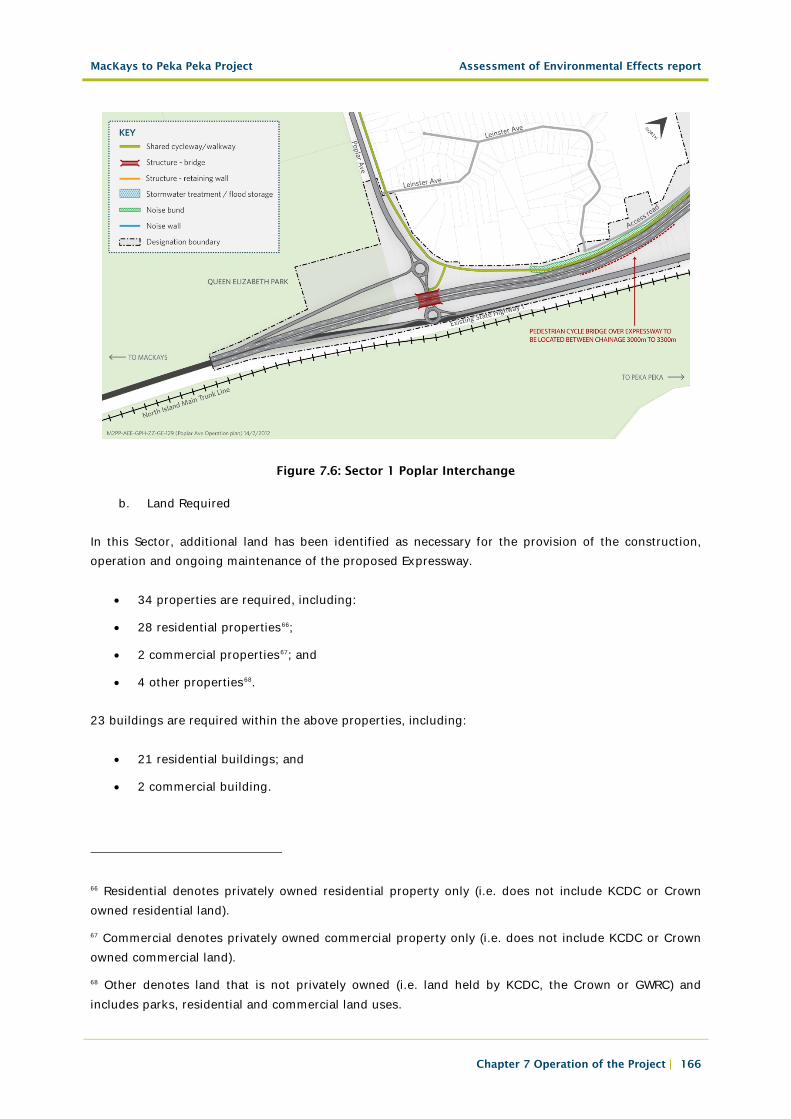
Figure 7.6: Sector 1 Poplar Interchange
b. Land Required
In this Sector, additional land has been identified as necessary for the provision of the construction, operation and ongoing maintenance of the proposed Expressway.
• 34 properties are required, including:
• 28 residential properties66;
• 2 commercial properties67; and
• 4 other properties68.
23 buildings are required within the above properties, including:
• 21 residential buildings; and
• 2 commercial building.
66 Residential denotes privately owned residential property only (i.e. does not include KCDC or Crown owned residential land).
67 Commercial denotes privately owned commercial property only (i.e. does not include KCDC or Crown owned commercial land).
68 Other denotes land that is not privately owned (i.e. land held by KCDC, the Crown or GWRC) and includes parks, residential and commercial land uses.
MacKays to Peka Peka Project Assessment of Environmental Effects report
Chapter 7 Operation of the Project | 167
Details on the specific properties required by the proposed Project designation within Sector 1 are outlined in the Land Requirement Plans, Volume 5.
c. Lighting
At the Poplar Avenue interchange, lighting would be low spill: for example, high-pressure sodium lamps (HPS), at the merge/diverge area, ramps, roundabouts and on Poplar Avenue.
Other lighting requirements for Sector 1 may include:
• Underbridge lights at Poplar Avenue and Raumati Road;
• Bridge uplighters at Poplar Avenue and Raumati Road;
• Flag lights at local road junctions;
• Flag lights at any junction of the cycleway/walkway with local roads; and
• Lighting of the cycleway/walkway from Raumati Road northward to Sector 2.
d. Noise Attenuation
The noise attenuation measures (with dimensions and locations approximated) proposed within Sector 1 are:
• A 2m high bund (with no barrier on top) extending 580m near the Leinster Avenue residential area, on the western side of the proposed Expressway; and
• An approximately 2m high noise barrier extending approximately 335m on the east side of the proposed Expressway, south of Raumati Road.
It is noted that:
• The surface of the proposed Expressway within Sector 1 is likely to be paved with low noise generating surfacing (e.g. OGPA) to provide additional mitigation of noise; and
• Concrete edge barriers would be provided on the proposed Expressway bridges crossing Poplar Avenue and Raumati Road.
Details of the dimensions and location of these likely noise attenuation measures are provided in Technical Report 15, Volume 3, with drawings contained within Volume 5.
e. Stormwater Treatment and Flood Management
Stormwater treatment within Sector 1 would be provided by a combination of wetlands and swales.
Flood management in Sector 1 would be achieved primarily by a combination of attenuation in swales and flood storage in the offset storage areas. The swales would be generally located on one or both sides of the proposed Expressway for the majority of Sector 1.
MacKays to Peka Peka Project Assessment of Environmental Effects report
Chapter 7 Operation of the Project | 168
In addition to the swales, stormwater treatment, attenuation and storage would be provided by:
• A 2,740m3 flood offset storage area 0B north of Drain 7, on the western side of the proposed Expressway, adjoining the existing Raumati wetland;
• A 4950m2/4960m3 stormwater treatment, attenuation and offset storage wetland 0A to the north of Drain 7, on the eastern side of the proposed Expressway; and
• A 8,292m3 flood offset storage area 0C adjoining the northern side of wetland 0A.
Culverts would be provided at the watercourses that cross the proposed Expressway within Sector 1. A Tributary of Drain 7 will require a diversion in order to avoid a culvert. The culverts and watercourse diversion proposed are detailed further in Technical Report 22, Volume 3.
Further details on all aspects of stormwater and hydrology within Sector 1 are provided in Technical Report 22, Volume 3 and illustrated on drainage layout drawings CV-SW-104 to 107, Volume 5.
f. Cycleway/Walkway
An approximately 3m wide shared cycleway/walkway would be located on the western side of the proposed Expressway through most of this Sector.
Approximately 200m west of the proposed Poplar Avenue roundabout (chainage 2600m) the proposed new cycleway/walkway would join the existing Poplar Avenue cycleway. From the Poplar Avenue roundabout (chainage 2700m) the cycleway/walkway would continue northward, separate from but generally parallel to the western shoulder of the proposed Expressway alignment.
The cycleway/walkway network would be connected into the existing SH1 between the two proposed local road roundabouts at chainage 2630m.
A cycleway/walkway overbridge is proposed between chainage 3000 and 3300m (with a bridge length of 58m, bridge width of 4m and a vertical clearance of 6m) , to provide an east/west connection across the proposed Expressway. The exact location of this bridge has yet to be determined, and will be the subject of a later Outline Plan to be submitted to KCDC.
The Project ‘s cycleway/walkway would include an additional southern east/west link by extending the network from chainage 4130m back to Lorna Irene Drive.
This cycleway/walkway has been designed to be compatible with GWRC proposals to construct additional cycleway/walkway facilities through, QE Park some time in the future.
g. Other Features
It is noted that the Project does not preclude the potential for a future Raumati railway station and an associated car park.
MacKays to Peka Peka Project Assessment of Environmental Effects report
Chapter 7 Operation of the Project | 169
7.3.2 Sector 2: Raumati/Paraparaumu
Sector 2 commences north of Raumati Road (chainage 4500m) to north of Mazengarb Road (chainage 8300m).
a. General Project Description
This section provides a general overview of the proposed Expressway alignment, bridges, interchange and local road connections within Sector 2:
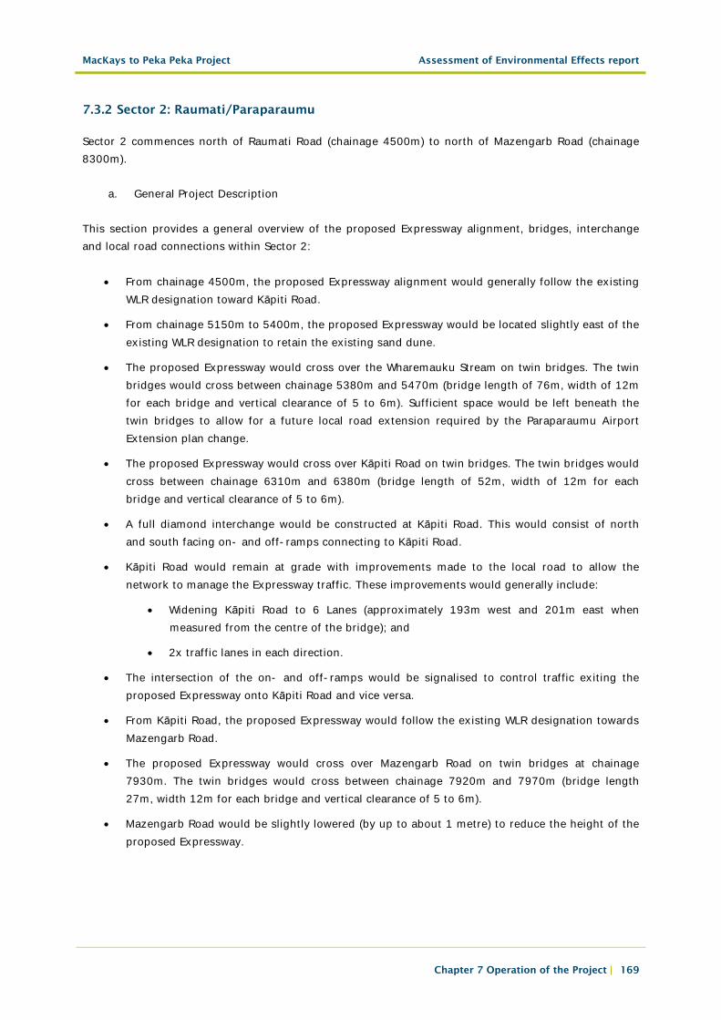
• From chainage 4500m, the proposed Expressway alignment would generally follow the existing WLR designation toward Kāpiti Road.
• From chainage 5150m to 5400m, the proposed Expressway would be located slightly east of the existing WLR designation to retain the existing sand dune.
• The proposed Expressway would cross over the Wharemauku Stream on twin bridges. The twin bridges would cross between chainage 5380m and 5470m (bridge length of 76m, width of 12m for each bridge and vertical clearance of 5 to 6m). Sufficient space would be left beneath the twin bridges to allow for a future local road extension required by the Paraparaumu Airport Extension plan change.
• The proposed Expressway would cross over Kāpiti Road on twin bridges. The twin bridges would cross between chainage 6310m and 6380m (bridge length of 52m, width of 12m for each bridge and vertical clearance of 5 to 6m).
• A full diamond interchange would be constructed at Kāpiti Road. This would consist of north and south facing on- and off-ramps connecting to Kāpiti Road.
• Kāpiti Road would remain at grade with improvements made to the local road to allow the network to manage the Expressway traffic. These improvements would generally include:
• Widening Kāpiti Road to 6 Lanes (approximately 193m west and 201m east when measured from the centre of the bridge); and
• 2x traffic lanes in each direction.
• The intersection of the on- and off-ramps would be signalised to control traffic exiting the proposed Expressway onto Kāpiti Road and vice versa.
• From Kāpiti Road, the proposed Expressway would follow the existing WLR designation towards Mazengarb Road.
• The proposed Expressway would cross over Mazengarb Road on twin bridges at chainage 7930m. The twin bridges would cross between chainage 7920m and 7970m (bridge length 27m, width 12m for each bridge and vertical clearance of 5 to 6m).
• Mazengarb Road would be slightly lowered (by up to about 1 metre) to reduce the height of the proposed Expressway.
MacKays to Peka Peka Project Assessment of Environmental Effects report
Chapter 7 Operation of the Project | 170
Figure 7.7: Sector 2 Kāpiti Interchange
b. Land Required
In this Sector, additional land has been identified as necessary for the provision of the construction, operation and ongoing maintenance of the proposed Expressway.
12 properties are required, including:
• 6 residential properties;
• 5 commercial properties; and
• 1 other property.
7 buildings are required within the above properties, including:
• 2 residential buildings;
• 4 commercial building; and
• 1 other building.
Details on the specific properties required by the proposed Project designation within Sector 2 are outlined in the Land Requirement Plans, Volume 5.
c. Lighting
Conventional HPS lighting would likely be used at the Kāpiti Road full interchange on the on- and off-ramps and on Kāpiti Road.
MacKays to Peka Peka Project Assessment of Environmental Effects report
Chapter 7 Operation of the Project | 171
Other lighting requirements for Sector 2 would include:
• Underbridge lights at Kāpiti Road and Mazengarb Road;
• Bridge uplighters at Kāpiti Road and Mazengarb Road;
• Lighting of Kāpiti Road;
• Flag lights at any junction of the cycleway/walkway with local roads; and
• Lighting of the cycleway/walkway between Raumati Road and Mazengarb Road.
d. Retaining Walls
Due to space constraints, approximately four retaining walls would be required for the full interchange at Kāpiti Road. These would likely be Mechanically Stabilised Earth walls ranging from a height of approximately 3 to 4m.
e. Noise Attenuation
The noise attenuation measures (with dimensions and locations approximated) that would likely be located within Sector 2 are:
i.West of the proposed Expressway, Raumati Road
• A 2m high noise barrier extending 240m to the north of Raumati Road and west of the proposed Expressway
ii.West of the proposed Expressway – South of Kāpiti Road
• A line of 2m high noise barriers along the common property boundaries of several properties;
• Proposed dune fill-in at the southern end;
• A 3m high noise barrier along the proposed Expressway and ramp; and
• A 2m high barrier is located along the proposed Expressway towards the bridge over Kāpiti Road.
iii.East of proposed Expressway – Kāpiti Road to Mazengarb Road area
• A 1.1m high concrete safety barrier along the southbound off-ramp and the proposed Expressway edge;
• Bunds between 2m and 3m would be placed along the eastern side of the proposed Expressway, along the southern half of this section of road.
• Bunds filling in gaps in the dunes along the northern half of this section of road. The infill bunds would have heights up to 7m, matching the dunes already existing between the proposed Expressway and the residential sites.
iv.West of proposed Expressway – Cheltenham Drive
• A 4m bund extending 225m
• A 2.5m barrier extending 295m
MacKays to Peka Peka Project Assessment of Environmental Effects report
Chapter 7 Operation of the Project | 172
It is noted that:
• The surface of the proposed Expressway would generally be paved with a low noise generating surface (for example, OGPA) throughout this Sector to provide additional noise mitigation;
• There would be dense asphalt on the Kāpiti Interchange ramps, and 1.1m concrete edge barriers on the proposed Expressway bridge over Kāpiti Road; and
• There would be 1.1 m high concrete edge barriers on the proposed Expressway bridge over Mazengarb Road.
Details of the dimensions and location of these likely noise attenuation measures are provided in Technical Report 15, Volume 3, with drawings contained within Volume 5.
f. Stormwater Treatment and Flood Management
Stormwater treatment in Sector 2 would be provided by a combination of wetlands and swales.
Flood management in Sector 2 would be achieved primarily by a combination of attenuation in swales and flood storage in the offset storage areas. The swales would be generally located on one or both sides of the proposed Expressway for the majority of Sector 2, except north of the Kāpiti Road interchange where stormwater would be collected by sumps and kerb and channel to be piped to the new wetland adjacent to Kāpiti Road.
In addition to the swales, stormwater treatment, attenuation and storage would be provided by:
• A 38,000m3 flood offset storage area 3A on the southern side of the Wharemauku Stream, west of the proposed Expressway;
• A 38,000m3 flood offset storage area 2 on the southern side of the Wharemauku Stream, east of the proposed Expressway;
• An 1800m2/2600m3 attenuation wetland (Wetland 3) located where the existing Kiwi Pond is currently sited on the southern side of the Wharemauku Stream, west of the proposed Expressway.
• A 9,384m2/6,250m3 treatment and attenuation wetland (Wetland 4) south of Kāpiti Road, east of the proposed Expressway;
• Wetland 4 has a treatment wetland at its core with an associated wider flood storage area positioned at a slightly higher level. This arrangement is common across many of the proposed wetlands where storage/attenuation is also required; and,
• A 6,000m2/6,234m3 treatment and attenuation wetland (Wetland 5) between Kāpiti Road and Mazengarb Road, west of the proposed Expressway. There is an alternative location for this wetland to the west on private land, as illustrated on drainage layout plan CV-SW-114, Volume 5. A private wetland is planned as part of a development and it may be beneficial to both parties if a single combined wetland were to be constructed.

MacKays to Peka Peka Project Assessment of Environmental Effects report
Chapter 7 Operation of the Project | 173
Wharemauku Stream would be crossed with a bridge and the remaining watercourses crossed by culverts. The culverts are listed within the Culverts and Watercourse Diversion Schedule, Appendix B of Technical Report 22, Volume 3.
Further details on all aspects of stormwater and hydrology within Sector 2 are provided in the Assessment of Hydrology and Stormwater Effects, Technical Report 22, Volume 3 and illustrated on drainage layout drawings CV-SW-108 to 114, Volume 5.
g. Cycle/Walkway
The new cycleway/walkway would be located parallel to but separate from the western shoulder of the proposed Expressway throughout this Sector.
At chainage 4930m, an additional cycleway/walkway connection would be provided to connect back to the local road network in the vicinity of 58 Kiwi Road.
The cycleway/walkway would be bridged over the Wharemauku Stream (at chainage 5400m) to provide north-south continuity for this network. There would also be a link between this network and the existing cycleway/walkway that runs east/west alongside the southern side of the Wharemauku Stream. From this bridge northward, the cycleway/walkway would cross Kāpiti Road and Mazengarb Road.
A cycleway/walkway overbridge is proposed between Kāpiti Road and Mazengarb Road between chainage 6900m and 7400m to provide an east/west connection over the proposed Expressway.
7.3.3 Sector 3: Otaihanga/Waikanae
Sector 3 commences north of Mazengarb Road (chainage 8300m) and ends to the north of Te Moana Road (chainage 12400).
From chainage 8300m to the Waikanae River, the proposed Expressway would generally follow the existing WLR designation alignment. The proposed Expressway would be located east of the existing WLR designation from north of the Waikanae River (at chainage 11100m) to the end of this Sector (chainage 12400m).
a. General Project Description
This section provides a general overview of the proposed Expressway alignment, bridges, interchange and local road connections within this sector:
• From the beginning of Sector 3 to Otaihanga Road the proposed Expressway would be located to the west of the Paraparaumu Sewage Treatment Plant (Designation 1110 within the Operative KCDC District Plan) and the Otaihanga Landfill (Designation 1119 within the Operative KCDC District Plan).
• The proposed Expressway would cross over Otaihanga Road; the bridge would have a length of 27m, a width of 25m and a vertical clearance of 5 to 6m.
• Otaihanga Road would remain at grade in its current location.
MacKays to Peka Peka Project Assessment of Environmental Effects report
Chapter 7 Operation of the Project | 174
• A new accessway would be provided for those properties on the eastern side of the proposed Expressway to the north of Otaihanga Road. This accessway would be located between Otaihanga Road at chainage 9200m and the existing paper road at chainage 9820m.
• The proposed Expressway would cross over the Waikanae River. The bridge would be approximately 182m long from a line of prominent sand dunes in the south to a constructed embankment in the north. The bridge would have four traffic lanes with a width of approximately 28m, a vertical clearance of approximately 7m and a cycleway/walkway “clipped69” on the eastern side.
• The Waikanae bridge would cross over a new access road from Kauri Road to the Waikanae Christian Holiday Camp (known as El Rancho) at chainage 10730m, located within the flood plain of the Waikanae River.
• The proposed Expressway would be located on the west side of the Maketu tree and to the east of the Takamore Urupā, both of which would be unaffected by the proposed Expressway.
• The proposed Expressway would follow the toe of the dune passing through the man-made ponds (at chainage 11250m), approximately 16m below the Takamore Urupā.
• Just beyond the location of the Takamore Urupā, the proposed Expressway would be cut through the dune which faces east before proceeding toward Te Moana Road.
• The proposed Expressway would cross over Te Moana Road and the Waimeha Stream between chainage 11760m and 11940m (bridge length of 142m, width of 25m and vertical clearance of 5 to 6m).
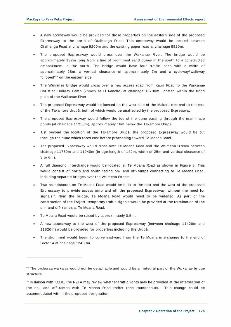
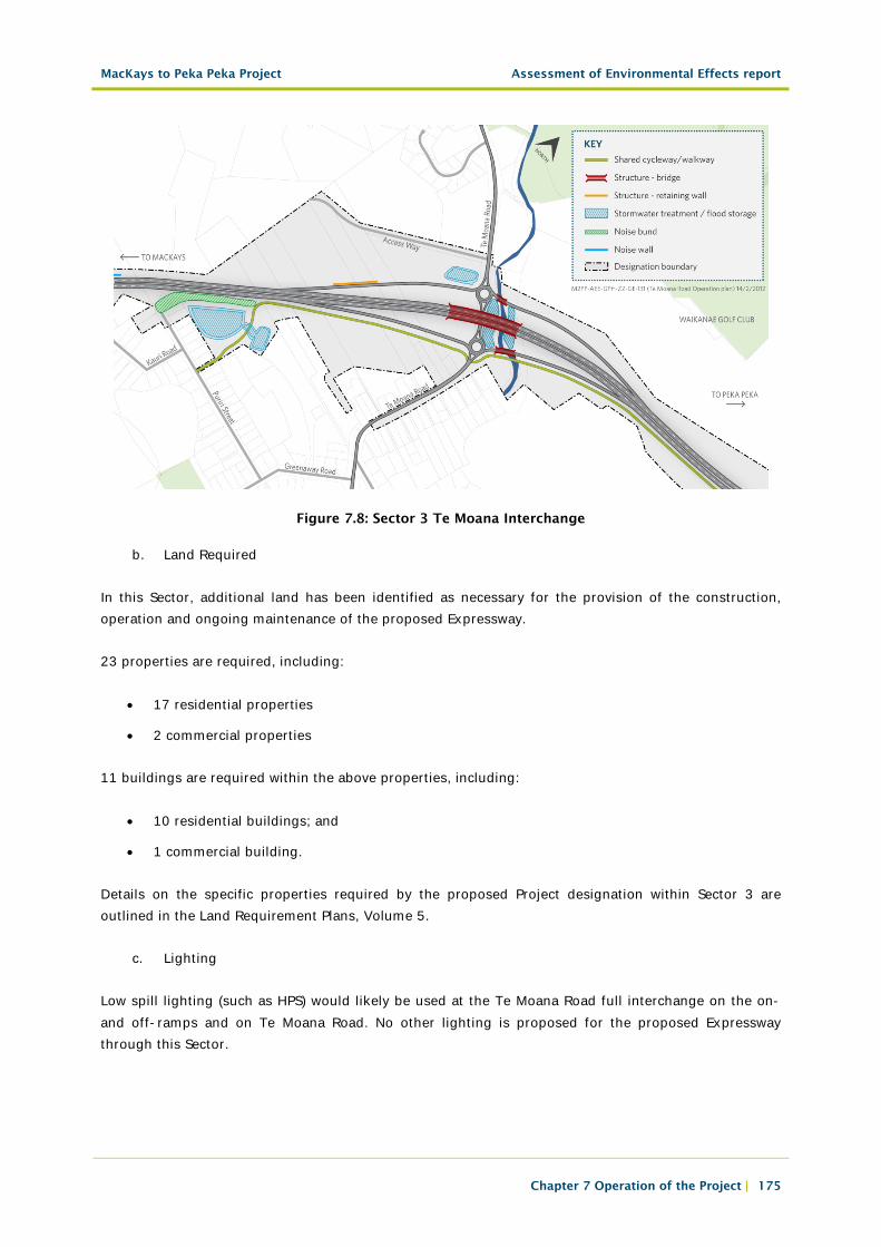
• A full diamond interchange would be located at Te Moana Road as shown in Figure 8. This would consist of north and south facing on- and off-ramps connecting to Te Moana Road, including separate bridges over the Waimeha Stream.
• Two roundabouts on Te Moana Road would be built to the east and the west of the proposed Expressway to provide access onto and off the proposed Expressway, without the need for signals70. Near the bridge, Te Moana Road would need to be widened. As part of the construction of the Project, temporary traffic signals would be provided at the termination of the on- and off-ramps at Te Moana Road.
• Te Moana Road would be raised by approximately 0.5m.
• A new accessway to the west of the proposed Expressway (between chainage 11420m and 11820m) would be provided for properties including the Urupā.
• The alignment would begin to curve eastward from the Te Moana interchange to the end of Sector 4 at chainage 12400m.
69 The cycleway/walkway would not be detachable and would be an integral part of the Waikanae bridge structure.
70 In liaison with KCDC, the NZTA may review whether traffic lights may be provided at the intersection of the on- and off-ramps with Te Moana Road rather than roundabouts. This change could be accommodated within the proposed designation.
MacKays to Peka Peka Project Assessment of Environmental Effects report
Chapter 7 Operation of the Project | 175
Figure 7.8: Sector 3 Te Moana Interchange
b. Land Required
In this Sector, additional land has been identified as necessary for the provision of the construction, operation and ongoing maintenance of the proposed Expressway.
23 properties are required, including:
• 17 residential properties
• 2 commercial properties
11 buildings are required within the above properties, including:
• 10 residential buildings; and
• 1 commercial building.
Details on the specific properties required by the proposed Project designation within Sector 3 are outlined in the Land Requirement Plans, Volume 5.
c. Lighting
Low spill lighting (such as HPS) would likely be used at the Te Moana Road full interchange on the on- and off-ramps and on Te Moana Road. No other lighting is proposed for the proposed Expressway through this Sector.
MacKays to Peka Peka Project Assessment of Environmental Effects report
Chapter 7 Operation of the Project | 176
Other lighting proposed would include:
• Underbridge lights at Te Moana Road;
• Bridge uplighters at Te Moana Road;
• Flag lights at local road junctions; and
• Flag lights at any junction of the cycleway/walkway with local roads.
d. Retaining Walls
Approximately two retaining walls would be required for Mazengarb Road on the western approach to the underpass. These would likely be Bored Piled walls ranging from a height of approximately 5m – 6m.
e. Noise Attenuation
The noise attenuation measures (with dimensions and locations approximated) that would likely be located within Sector 3 are:
i.West of proposed Expressway – Mazengarb Road area
• A 2m high barrier immediately adjacent to the proposed Expressway, extending from the bridge across Mazengarb Road to chainage 8420.
ii.East of proposed Expressway – Mazengarb Road area
• A 2m high barrier extending from the bridge over Mazengarb Road past the dwellings.
iii.Otaihanga Road area
• Extension of the 1.1m high bridge barrier.
iv.East of proposed Expressway – Kauri Road area
• A 3m high bund extending for approximately 280m along the eastern side of the proposed Expressway.
v.West of proposed Expressway – South of Te Moana Road
• OGPA on Te Moana Road.
vi.West of proposed Expressway – North of Te Moana Road
• OGPA on Te Moana Road.
It is noted that:
• The surface of the proposed Expressway would generally be paved with low noise surfacing (such as OGPA) throughout this Sector to provide additional noise mitigation.
MacKays to Peka Peka Project Assessment of Environmental Effects report
Chapter 7 Operation of the Project | 177
Details of the dimensions and location of these likely noise attenuation measures are provided in Technical Report 15, Volume 3, with drawings contained within Volume 5.
f. Stormwater Treatment and Flood Management
Stormwater treatment in Sector 3 would be provided by a combination of wetlands and swales.
Flood management in Sector 3 would be achieved primarily by a combination of attenuation in swales and flood storage in the offset storage areas. The swales would be generally located on one or both sides of the proposed Expressway for the majority of Sector 3. Where swales cannot be provided immediately, stormwater would drain to swales or wetlands nearby.
In addition to the swales, stormwater treatment, attenuation and storage would be provided by:
• A 4,854m3 attenuation and offset storage wetland (Wetland 6), opposite the Waste Water Treatment Plant Drain, west of the proposed Expressway;
• A 1,790m3 flood offset storage area 6A located at the landfill, to the east of the proposed Expressway;
• A 7,800m2/1850m3 treatment and attenuation wetland (Wetland 8) on the southern side of the Waikanae River, east of the proposed Expressway;
• A 1,613m3 flood offset storage area 9A on the northern side of the Waikanae River, east of the proposed Expressway;
• A 4,832m2 /6206m3 treatment, attenuation and offset storage wetland (Wetland 9) north of Puriri Road, east of the proposed Expressway;
• A 750m3 attenuation wetland (Wetland 10) to the south of Te Moana Road, west of the proposed Expressway; and
• A potential additional 5000m3 flood offset storage area for the isolated catchment located near chainage 12100m, subject to property negotiations. The proposed Expressway designation has sufficient area to provide for the offset volume to be constructed if an agreement is not reached over this issue with the property owner (refer to Technical Report 22, Volume 3).
Culverts would be provided to cross some watercourses and provide for flood events within Sector 3. At its confluence with the Waikanae River, the Muaupoko Stream would require a diversion as a result of the Project. The culverts and watercourse diversion proposed are listed within the Culverts and Watercourse Diversion Schedule, Appendix B of Technical Report 22, Volume 3.
Extensive works would be required within the Waikanae River channel (in and around the location of the proposed Waikanae Bridge), as detailed within Technical Report 22, Volume 3.
Further details on all aspects of stormwater and hydrology are provided in the Assessment of Hydrology and Stormwater Effects, Technical Report 22, Volume 3 and illustrated on drainage layout drawings CV-SW-115 to 120, Volume 5.

MacKays to Peka Peka Project Assessment of Environmental Effects report
Chapter 7 Operation of the Project | 178
g. Cycle/Walkway
The cycleway/walkway would continue parallel to, but separated from, the western boundary of the proposed Expressway from Mazengarb Road to Otaihanga Road. At Otaihanga Road, the cycleway/walkway would re-connect with this local road, following it east approximately 80m, where it would recommence in parallel to, but separated from, the eastern side of the proposed Expressway at chainage 9200m, and continues north.
Immediately south of the Waikanae River, the cycleway/walkway network would run parallel to the eastern boundary of the proposed Expressway. At chainage 10500m the cycleway/walkway would branch into two parts, one part crossing over the Waikanae River Bridge on a “clip-on” cycle/walkway bridge to the eastern shoulder of the proposed Expressway and the other part reconnecting to the existing east/west pathway along the southern banks of the Waikanae River.
At chainage 10800m, just north of the Waikanae Bridge, the cycleway/walkway would divert onto the local road network before emerging to the north of Puriri Road (at chainage 11200m) to continue adjacent to the eastern side of the proposed Expressway for the remainder of this Sector, crossing Te Moana Road at grade.
7.3.4 Sector 4: Waikanae North
Sector 4 commences north of Te Moana Road (chainage 12400m) and ends to the north of Peka Peka Road (chainage 18050m).
The alignment would pass to the east of the existing WLR designation between Te Moana Road and Ngarara Road, to avoid the QEII covenant ecological area, and then would generally continue within the existing WLR designation from chainage 13300m to a point just short of existing SH1 near Peka Peka Road at chainage 16000m. The proposed Expressway would digress northward from the existing WLR designation beyond chainage 16000m to either the existing SH1 network or the proposed Peka Peka to Ōtaki Expressway (depending on the compatibility of Project completion dates) at chainage 18050m.
a. General Project Description
This section provides a general overview of the proposed Expressway alignment, bridges, interchange and local road connections within this sector:
• Between chainage 12400m and 13550m the proposed Expressway would be located to the east of the large QEII covenanted area between Te Moana Road and Ngarara Road.
• The proposed Expressway would pass under Ngarara Road at chainage 13550m. Ngarara Road would become a bridge over the proposed Expressway and would require realignment (bridge length of 73m, width of 15m and vertical clearance of 6m).
• A new local road is proposed. This new local road would be bridged over the proposed Expressway at chainage 13950m to provide access to properties currently serviced by Smithfield Road and also the Nga Manu nature reserve on the eastern side of the alignment (bridge length of 70m, width of 16m and vertical clearance of 6m).
MacKays to Peka Peka Project Assessment of Environmental Effects report
Chapter 7 Operation of the Project | 179
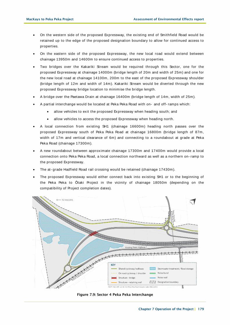
• On the western side of the proposed Expressway, the existing end of Smithfield Road would be retained up to the edge of the proposed designation boundary to allow for continued access to properties.
• On the eastern side of the proposed Expressway, the new local road would extend between chainage 13950m and 14600m to ensure continued access to properties.
• Two bridges over the Kakariki Stream would be required through this Sector, one for the proposed Expressway at chainage 14000m (bridge length of 20m and width of 25m) and one for the new local road at chainage 14100m, 200m to the east of the proposed Expressway shoulder (bridge length of 12m and width of 14m). Kakariki Stream would be diverted through the new proposed Expressway bridge location to minimise the bridge length.
• A bridge over the Paetawa Drain at chainage 16400m (bridge length of 14m, width of 25m).
• A partial interchange would be located at Peka Peka Road with on- and off-ramps which:
• allow vehicles to exit the proposed Expressway when heading south; and
• allow vehicles to access the proposed Expressway when heading north.
• A local connection from existing SH1 (chainage 16600m) heading north passes over the proposed Expressway south of Peka Peka Road at chainage 16800m (bridge length of 87m, width of 17m and vertical clearance of 6m) and connecting to a roundabout at grade at Peka Peka Road (chainage 17300m).
• A new roundabout between approximate chainage 17300m and 17400m would provide a local connection onto Peka Peka Road, a local connection northward as well as a northern on-ramp to the proposed Expressway.
• The at-grade Hadfield Road rail crossing would be retained (chainage 17430m).
• The proposed Expressway would either connect back into existing SH1 or to the beginning of the Peka Peka to Ōtaki Project in the vicinity of chainage 18050m (depending on the compatibility of Project completion dates).
Figure 7.9: Sector 4 Peka Peka Interchange

MacKays to Peka Peka Project Assessment of Environmental Effects report
Chapter 7 Operation of the Project | 180
b. Land Required
In this Sector, additional land has been identified as necessary for the construction, operation and ongoing maintenance of the proposed Expressway. 15 residential properties are required, within which 9 residential buildings are required.
• Details on the specific properties required by the proposed Project designation within Sector 4 are outlined in the Land Requirement Plans, Volume 5.
c. Lighting
Low spill e.g. HPS lighting would be used on the Peka Peka partial interchange merge/diverge area, ramps, roundabouts and approaches.
Other lighting requirements in Sector 4 would likely include:
• Flag lights at local road junctions; and
• Flag lights at any junction of the cycleway/walkway with local roads.
d. Retaining Walls
A retaining wall would be required for the proposed Nga Manu Access Road. This wall is expected to be a Bored Piled walls, approximately 1 to 2m high.
e. Noise Attenuation
The noise attenuation measures (with dimensions and locations approximated) that would likely be used within Sector 4 are:
i.East of proposed Expressway – End Farm Road
• Use of OGPA, continuing on from the new Smithfield Road bridge, extending from approximately chainage 14600m to chainage 15400m.
ii.West of proposed Expressway – Peka Peka Road
• Use of OGPA.
Details of the dimensions and location of these likely noise attenuation measures are provided in Technical Report 15, Volume 3, with drawings contained within Volume 5.
f. Stormwater Treatment and Flood Management
Stormwater treatment in Sector 4 would be provided by a combination of wetlands and swales.
Flood management in Sector 4 would be achieved primarily by a combination of attenuation in swales and flood storage in the offset storage areas. The swales would generally be located on one or both
MacKays to Peka Peka Project Assessment of Environmental Effects report
Chapter 7 Operation of the Project | 181
sides of the proposed Expressway for the majority of Sector 4. Where swales cannot be provided immediately, stormwater would drain to swales or wetlands nearby.
In addition to the swales, stormwater treatment, attenuation and storage would be provided by:
• A 1,500m3 flood offset storage area 10C near chainage 12900m, east of the proposed Expressway;
• A 450m2 treatment wetland (Wetland 10A) north of Ngarara Creek, west of the proposed Expressway;
• A 1,020m2 treatment wetland (Wetland 10B) south of Ngarara Creek , east of the proposed Expressway;
• A 500m3 flood offset storage area 10D between Ngarara Creek and Ngarara Road, west of the proposed Expressway;
• A 200m2 treatment wetland (Wetland 11A) to the south of the Kakariki Stream, east of the proposed Expressway;
• A 25,000m3 flood offset storage area 11, to the north of the Kakariki Stream, east of the proposed Expressway;
• A 786m2/782m3 treatment and attenuation wetland (Wetland 12) between chainage 14200m and 14300m, east of the proposed Expressway;
• A 250m2 treatment wetland (Wetland 11B) between chainage 14300 and 14400m, east of the proposed Expressway;
• A 6,000m3 flood offset storage area 13, to the north of the Paetawa Drain, on the eastern side of the proposed Expressway; and
• A 30,000m3 flood offset storage area 13A opposite area 13, split by the new local road and east of the proposed Expressway.
Culverts would be provided to cross some watercourses and provide for flood events within Sector 4. A number of watercourses within Sector 4 would require diversions as a result of the Project. The culverts and watercourse diversions proposed are listed within the Culverts and Watercourse Diversion Schedule, Appendix B of Technical Report 22, Volume 3.
Further details on all aspects of stormwater and hydrology within Sector 4 are provided in the Assessment of Hydrology and Stormwater Effects, Technical Report 22, Volume 3 and illustrated on drainage layout drawings CV-SW-120 to 132, Volume 5.
g. Cycle/Walkway
The cycleway/walkway would be located in parallel to, but separated from, the eastern side of the proposed Expressway before crossing over Ngarara Road (chainage 13550m) and continuing in parallel, but separated from, the western side of the proposed Expressway to Te Kowhai Road).