Embed Size (px)
Citation preview

CUSTOMER APPROVE
DATE:
VENDOR APPROVE
Issued/Checked/Approved
DATE: Nov. 16, 2021
NextGen Components, Inc. [email protected] www.NextGenComponent.com
SPECIFICATION SHEET NO. N1116- SOT23S9014S0J6
DATE Nov. 16, 2021
REVISION A1
DESCRIPITION SMD Plastic-Encapsulate Transistors, SOT-23 series, 3 pads
S9014 Type, NPN
Collector Power Dissipation 200mW. Collector Current 100mA Max.
Operating Temp. Range -55°C ~+150°C
Package in Tape/Reel, 3000pcs/Reel
RoHS/RoHS III compliant
CUSTOMER
CUSTOMER PART NUMBER
CROSS REF. PART NUMBER
ORIGINAL PART NUMBER MDD S9014
PART CODE SOT23S9014S0J6
SPECIFICATION SHEET
PART CODE: SOT23S9014S0J6
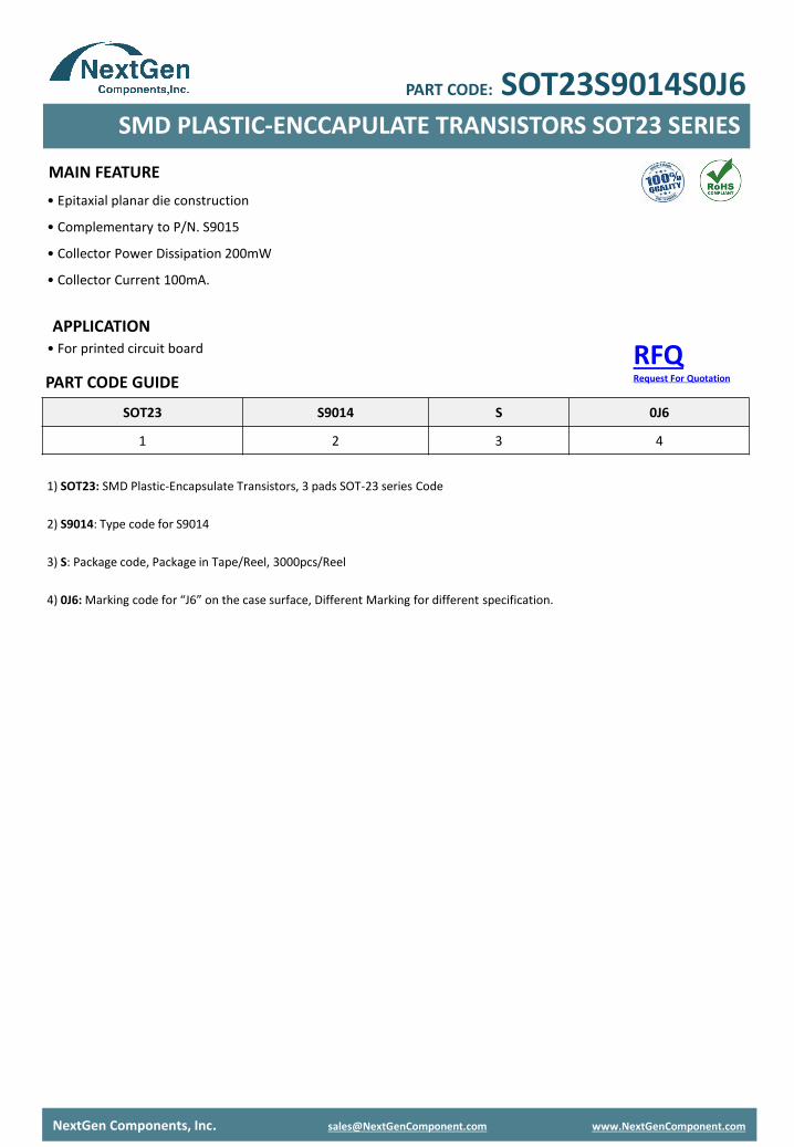
• Epitaxial planar die construction
• Complementary to P/N. S9015
• Collector Power Dissipation 200mW
• Collector Current 100mA.
MAIN FEATURE
APPLICATION
PART CODE GUIDE
RFQRequest For Quotation
SMD PLASTIC-ENCCAPULATE TRANSISTORS SOT23 SERIES
NextGen Components, Inc. [email protected] www.NextGenComponent.com
PART CODE: SOT23S9014S0J6
• For printed circuit board
SOT23 S9014 S 0J6
1 2 3 4
1) SOT23: SMD Plastic-Encapsulate Transistors, 3 pads SOT-23 series Code
2) S9014: Type code for S9014
3) S: Package code, Package in Tape/Reel, 3000pcs/Reel
4) 0J6: Marking code for “J6” on the case surface, Different Marking for different specification.
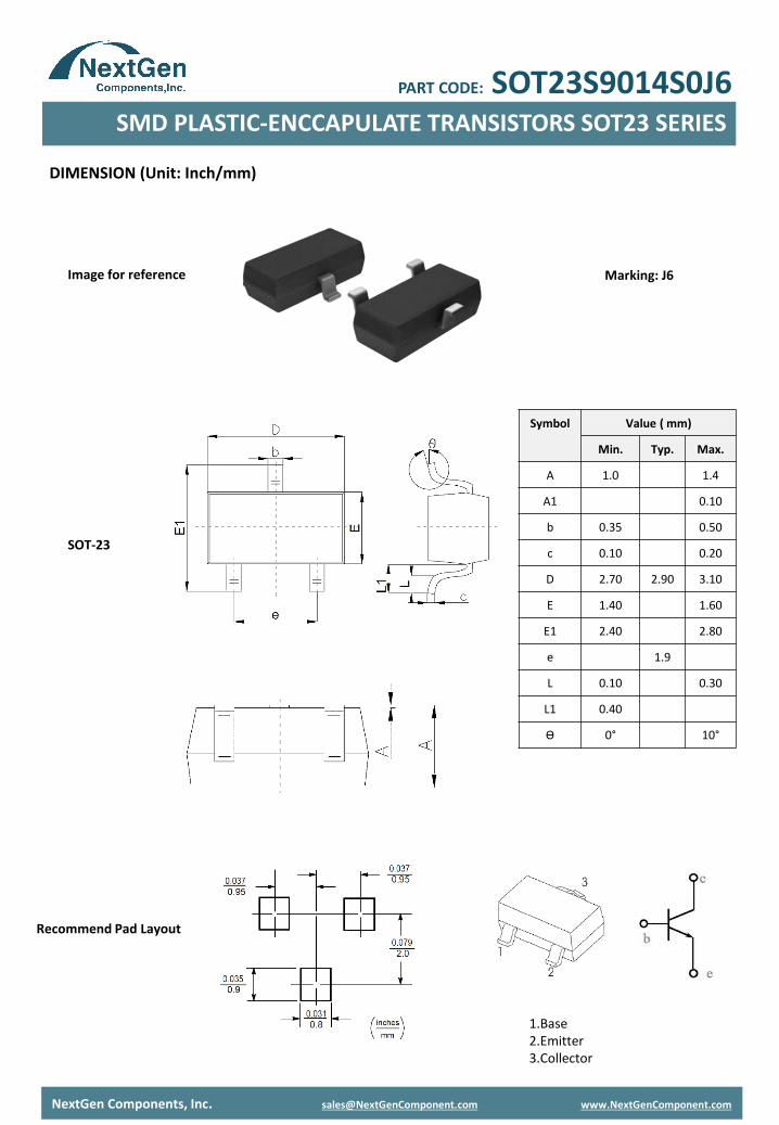
DIMENSION (Unit: Inch/mm)
Image for reference
Recommend Pad Layout
SOT-23
NextGen Components, Inc. [email protected] www.NextGenComponent.com
Symbol Value ( mm)
Min. Typ. Max.
A 1.0 1.4
A1 0.10
b 0.35 0.50
c 0.10 0.20
D 2.70 2.90 3.10
E 1.40 1.60
E1 2.40 2.80
e 1.9
L 0.10 0.30
L1 0.40
Ɵ 0° 10°
Marking: J6
SMD PLASTIC-ENCCAPULATE TRANSISTORS SOT23 SERIES
PART CODE: SOT23S9014S0J6
1.Base2.Emitter3.Collector
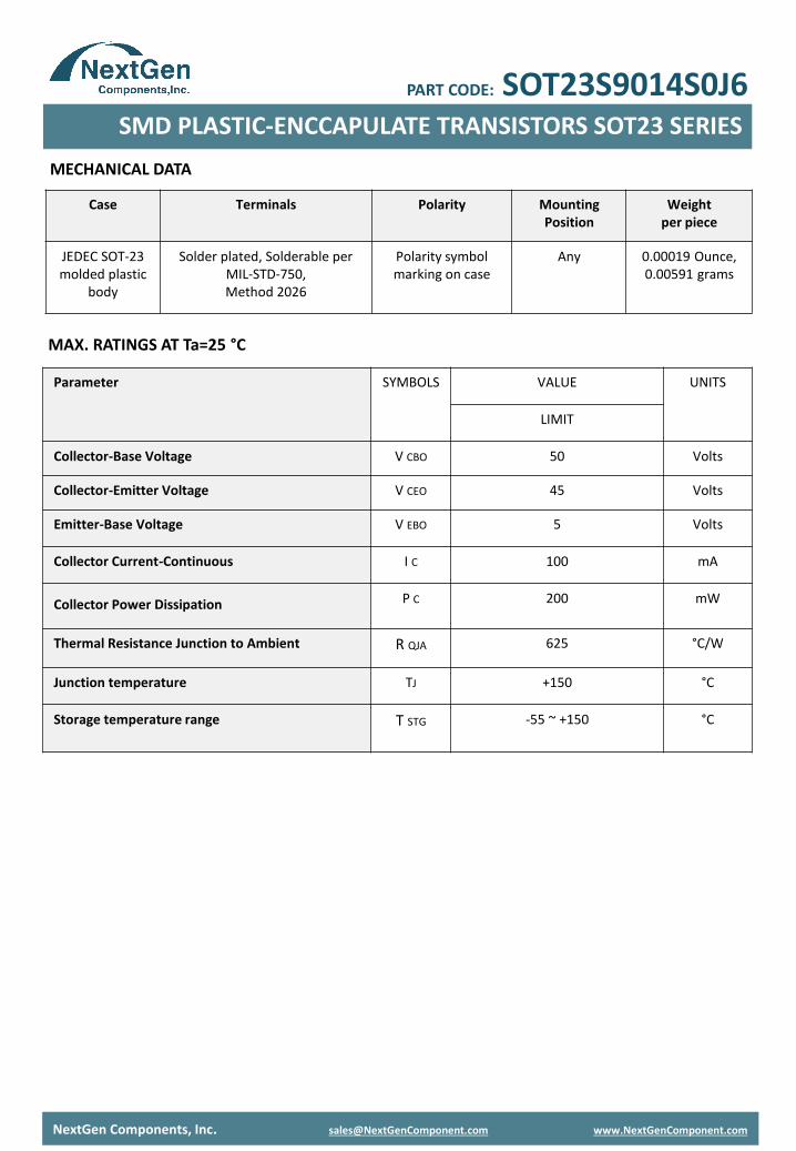
MAX. RATINGS AT Ta=25 °C
MECHANICAL DATA
Parameter SYMBOLS VALUE UNITS
LIMIT
Collector-Base Voltage V CBO 50 Volts
Collector-Emitter Voltage V CEO 45 Volts
Emitter-Base Voltage V EBO 5 Volts
Collector Current-Continuous I C 100 mA
Collector Power Dissipation P C 200 mW
Thermal Resistance Junction to Ambient R QJA 625 °C/W
Junction temperature TJ +150 °C
Storage temperature range T STG -55 ~ +150 °C
Case Terminals Polarity Mounting Position
Weight per piece
JEDEC SOT-23 molded plastic
body
Solder plated, Solderable per MIL-STD-750,Method 2026
Polarity symbol marking on case
Any 0.00019 Ounce, 0.00591 grams
NextGen Components, Inc. [email protected] www.NextGenComponent.com
SMD PLASTIC-ENCCAPULATE TRANSISTORS SOT23 SERIES
PART CODE: SOT23S9014S0J6
NextGen Components, Inc. [email protected] www.NextGenComponent.com
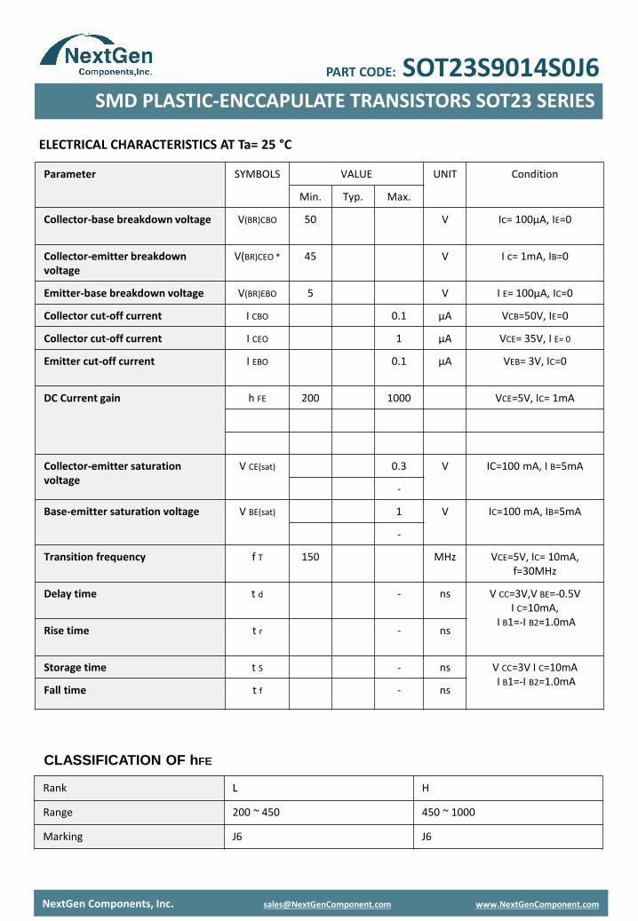
Parameter SYMBOLS VALUE UNIT Condition
Min. Typ. Max.
Collector-base breakdown voltage V(BR)CBO 50 V Ic= 100μA, IE=0
Collector-emitter breakdown voltage
V(BR)CEO * 45 V I c= 1mA, IB=0
Emitter-base breakdown voltage V(BR)EBO 5 V I E= 100μA, IC=0
Collector cut-off current I CBO 0.1 µA VCB=50V, IE=0
Collector cut-off current I CEO 1 µA VCE= 35V, I E= 0
Emitter cut-off current I EBO 0.1 µA VEB= 3V, IC=0
DC Current gain h FE 200 1000 VCE=5V, IC= 1mA
Collector-emitter saturation voltage
V CE(sat) 0.3 V IC=100 mA, I B=5mA
-
Base-emitter saturation voltage V BE(sat) 1 V IC=100 mA, IB=5mA
-
Transition frequency f T 150 MHz VCE=5V, IC= 10mA, f=30MHz
Delay time t d - ns V CC=3V,V BE=-0.5VI C=10mA,
I B1=-I B2=1.0mARise time t r - ns
Storage time t S - ns V CC=3V I C=10mAI B1=-I B2=1.0mA
Fall time t f - ns
ELECTRICAL CHARACTERISTICS AT Ta= 25 °C
SMD PLASTIC-ENCCAPULATE TRANSISTORS SOT23 SERIES
PART CODE: SOT23S9014S0J6
Rank L H
Range 200 ~ 450 450 ~ 1000
Marking J6 J6
CLASSIFICATION OF hFE

RELIABILITY
Number Experiment Items Experiment Method And Conditions Reference Documents
1 Solder Resistance Test Test 260°C± 5°C for 10 ± 2 sec.Immerse body into solder 1/16” ± 1/32"
MIL-STD-750D METHOD-2031.2
2 Solderability Test 230°C ±5°C for 5 sec. MIL-STD-750D METHOD-2026.1 0
3 Pull Test 1 kg in axial lead direction for 10 sec. MIL-STD-750D METHOD-2036.4
4 Bend Test 0.5Kg Weight Applied To Each Lead, Bending Arcs 90 °C ± 5 °C For 3 Times
MIL-STD-750D METHOD-2036.4
5 High Temperature Reverse Bias Test
TA=100°C for 1000 Hours at VR=80% Rated VR
MIL-STD-750D METHOD-1038.4
6 Forward Operation Life Test TA=25°C Rated Average Rectified Current
MIL-STD-750D METHOD-1027.3
7 Intermittent Operation Life Test
On state: 5 min with rated IRMS PowerOff state: 5 min with Cool Forced Air.
On and off for 1000 cycles.
MIL-STD-750D METHOD-1036.3
8 Pressure Cooker Test 15 PSIG, TA=121°C, 4 hours MIL-S-19500 APPENOIXC
9 Temperature Cycling Test -55°C~+125°C; 30 Minutes For Dwelled Time 5 minutes for transferred time.
Total: 10 cycles.
MIL-STD-750D METHOD-1051.7
10 Thermal Shock Test 0°C for 5 minutes., 100°C for 5minutes, Total: 10 cycles
MIL-STD-750D METHOD-1056.7
11 Forward Surge Test 8.3ms Single Sale Sine-wave One Surge. MIL-STD-750D METHOD-4066.4
12 Humidity Test TA=65°C, RH=98% for 1000 hours. MIL-STD-750D METHOD-1021.3
13 High Temperature Storage life Test
150°C for 1000 Hours MIL-STD-750D METHOD-1031.5
NextGen Components, Inc. [email protected] www.NextGenComponent.com
SMD PLASTIC-ENCCAPULATE TRANSISTORS SOT23 SERIES
PART CODE: SOT23S9014S0J6

SUGGESTED REFLOW PROFILE (For Reference Only)
NextGen Components, Inc. [email protected] www.NextGenComponent.com
• Recommended peak temperature is over 245℃, If peak temperature is below 245 ℃, you may adjust the
following parameters; time length of peak temperature (longer), time length of soldering (longer), thickness of
solder paste (thicker)
• Welding shall not exceed 2 times
• Remark: lead free solder paste (96.5 sn/3.0 Ag/0.5Cu)
SMD PLASTIC-ENCCAPULATE TRANSISTORS SOT23 SERIES
PART CODE: SOT23S9014S0J6
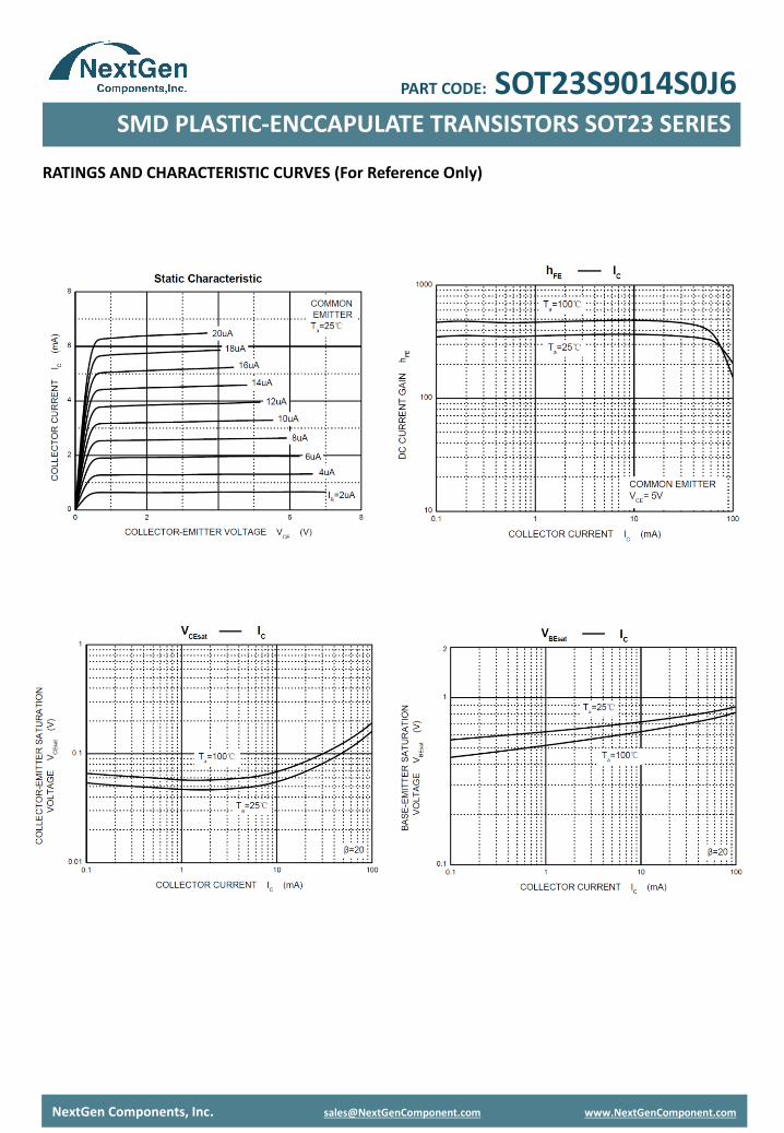
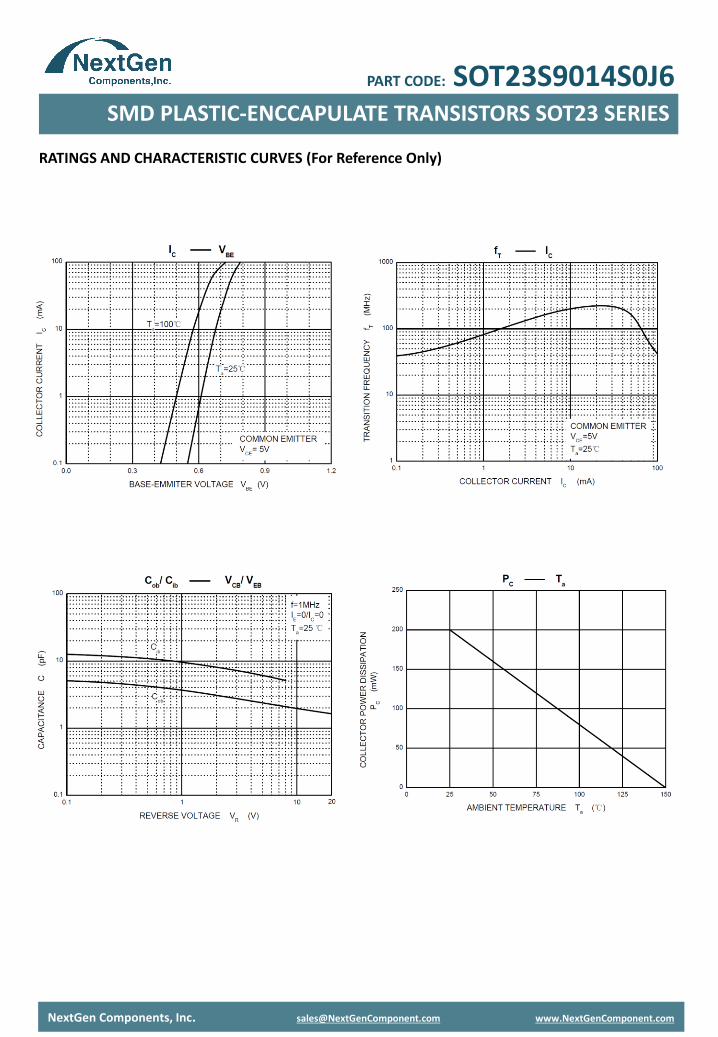
RATINGS AND CHARACTERISTIC CURVES (For Reference Only)
NextGen Components, Inc. [email protected] www.NextGenComponent.com
SMD PLASTIC-ENCCAPULATE TRANSISTORS SOT23 SERIES
PART CODE: SOT23S9014S0J6
RATINGS AND CHARACTERISTIC CURVES (For Reference Only)
NextGen Components, Inc. [email protected] www.NextGenComponent.com
SMD PLASTIC-ENCCAPULATE TRANSISTORS SOT23 SERIES
PART CODE: SOT23S9014S0J6

TAPE/REEL (Unit: mm)
All Devices are packed in accordance with EIA standard RS-481-A and specifications.
NextGen Components, Inc. [email protected] www.NextGenComponent.com
Item Symbol Tolerance SOT-23
Carrier width A 0.1 3.15
Carrier Length B 0.1 2.77
Carrier Depth C 0.1 1.22
Sprocket hole d 0.05 1.55
7”Reel outside diameter D 2.0 178.00
7”Reel inner diameter D1 Min. 54.4
Feed hole diameter D2 0.5 13.00
Sprocket hole position E 0.1 1.75
Punch hole position F 0.1 3.50
Punch hole pitch P 0.1 4.00
Sprocket hole pitch P0 0.1 4.00
Embossment center P1 0.1 2.00
Overall tape thickness T 0.1 0.25
Tape width W 0.3 8.00
Reel width W1 1.0 19.50
SMD PLASTIC-ENCCAPULATE TRANSISTORS SOT23 SERIES
PART CODE: SOT23S9014S0J6

NextGen Component, Inc. reserves the right to make changes to the product(s) and or information contained herein without notice. No liability is assumed as a result of their use or application. No rights under any patent accompany the sale of any such product(s) or information
DISCLAIMER
NextGen Components, Inc. [email protected] www.NextGenComponent.com
PACKAGE
SMD PLASTIC-ENCCAPULATE TRANSISTORS SOT23 SERIES
PART CODE: SOT23S9014S0J6
Case Code SOT-23
Reel Size 7”
Reel Size 178 mm
MPQ/Reel 3000 pcs
Qty. /Box 6000 pcs
G.W/Box 1 LBS