Embed Size (px)
Citation preview
STANDARD SPECIFICATION FOR MEDIUM AND LOW VOLTAGE ELECTRICITY DISTRIBUTION WORKS
PART B-03: OVERHEAD CONDUCTOR DISTRIBUTION, ABC, 3.3, 6.6, 11, 22, 33kV
Infrastructure Technical Standards Page B-03:1
PART B-03 TITLE: OVERHEAD CONDUCTOR DISTRIBUTION (ABC, 3.3, 6.6, 11, 22, 33kV) SPECIFICTION NO: B-03, ABC, 3.3, 6.6, 11, 22, 33kV INCEPTION DATE: AFTER GAZETTING (WORKING DOCUMENT FOR A 3 YEAR PERIOD) AMENDMENTS / REVISIONS
DATE PAGE PARAGRAPH DESCRIPTION ORIGINATOR APPROVED
STANDARD SPECIFICATION FOR MEDIUM AND LOW VOLTAGE ELECTRICITY DISTRIBUTION WORKS
PART B-03: OVERHEAD CONDUCTOR DISTRIBUTION, ABC, 3.3, 6.6, 11, 22, 33kV
Infrastructure Technical Standards Page B-03:2
TABLE OF CONTENTS PAGE
1 SCOPE ............................................................................................................................................ 5
2 TREE CUTTING .............................................................................................................................. 9
3 POLES ............................................................................................................................................. 9
3.1 GENERAL.................................................................................................................................... 9 3.2 POLE SPACING ............................................................................................................................ 9 3.3 POLE PLANTING .......................................................................................................................... 9 3.4 POLE EARTHING .......................................................................................................................... 9 3.5 WOODEN POLES ....................................................................................................................... 10
3.5.1 General specification ....................................................................................................... 10 3.6 CONCRETE POLES ..................................................................................................................... 11
3.6.1 General ............................................................................................................................ 11 3.6.2 Design ............................................................................................................................. 11 3.6.3 Length, tip and butt dimension ........................................................................................ 11 3.6.4 Cover of reinforcement .................................................................................................... 11 3.6.5 Finish ............................................................................................................................... 11 3.6.6 Holes ............................................................................................................................... 12 3.6.7 Pole Strength ................................................................................................................... 12
3.7 MONOPOLE STEEL STRUCTURES ............................................................................................... 12 3.7.1 Design ............................................................................................................................. 12 3.7.2 Paint and Finishing .......................................................................................................... 12
4 STAY ASSEMBLIES ..................................................................................................................... 13
4.1 GENERAL.................................................................................................................................. 13 4.2 STAYWIRE ................................................................................................................................ 13
4.2.1 General ............................................................................................................................ 13 4.2.2 Stay wire for MV line ....................................................................................................... 13 4.2.3 Stay wire for LV line ........................................................................................................ 13
4.3 STAY ROD ................................................................................................................................. 13 4.4 STAY ROD BASE PLATE .............................................................................................................. 14
4.4.1 Base plate for MV line stay rod ....................................................................................... 14 4.4.2 Base plate for LV line stay rod ........................................................................................ 14
4.5 PREFORMED STAY FITTINGS ....................................................................................................... 14 4.5.1 General ............................................................................................................................ 14 4.5.2 Pole top make off ............................................................................................................ 14 4.5.3 Preformed guy grips ........................................................................................................ 14
4.6 STAY INSULATOR....................................................................................................................... 14 4.7 STAY GUARDS ........................................................................................................................... 15 4.8 OTHER STAY ACCESSORIES ....................................................................................................... 15
4.8.1 Cable clamps ................................................................................................................... 15 4.8.2 Eye-bolt assembly ........................................................................................................... 15
5 EXCAVATION ............................................................................................................................... 16
5.1 GENERAL.................................................................................................................................. 16 5.2 POLE HOLE EXCAVATION ............................................................................................................ 16 5.3 STAY HOLE EXCAVATION ............................................................................................................ 17 5.4 COMPACTING OF HOLES ............................................................................................................ 17 5.5 ROCK ANCHORS ....................................................................................................................... 17
6 LINE CONFIGURATION ............................................................................................................... 18
STANDARD SPECIFICATION FOR MEDIUM AND LOW VOLTAGE ELECTRICITY DISTRIBUTION WORKS
PART B-03: OVERHEAD CONDUCTOR DISTRIBUTION, ABC, 3.3, 6.6, 11, 22, 33kV
Infrastructure Technical Standards Page B-03:3
6.1 GENERAL.................................................................................................................................. 18 6.1.1 Galvanizing ...................................................................................................................... 18 6.1.2 Bolts and nuts .................................................................................................................. 18
6.2 A-FRAME CONFIGURATION ......................................................................................................... 18 6.2.1 Strain A-frame ................................................................................................................. 18 6.2.2 Intermediate A-frame ....................................................................................................... 19
6.3 VERTICAL STAGGERED DELTA CONFIGURATION ........................................................................... 19 6.3.1 Strain Staggered Delta .................................................................................................... 19 6.3.2 Intermediate Staggered Delta ......................................................................................... 19
7 LINE CONDUCTOR ...................................................................................................................... 20
7.1 GENERAL.................................................................................................................................. 20 7.2 CONDUCTOR SIZE ..................................................................................................................... 20 7.3 LINE JOINTS .............................................................................................................................. 20 7.4 MINIMUM ELECTRICAL CLEARANCES (VERTICAL CLEARANCES) ..................................................... 21 7.5 MINIMUM ELECTRICAL CLEARANCES (GUIDELINES FOR BUILDINGS AND PARALLEL LINES) ............... 23 7.6 POWER LINE AND COMMUNICATION LINE CROSSINGS ................................................................... 23
8 INSULATORS ................................................................................................................................ 24
8.1 GENERAL.................................................................................................................................. 24 8.1.1 Types of insulators .......................................................................................................... 24 8.1.2 Electrical design .............................................................................................................. 24 8.1.3 Mechanical design ........................................................................................................... 24 8.1.4 Clamps and conductor fittings ......................................................................................... 24
8.2 STRAIN INSULATORS.................................................................................................................. 25 8.2.1 Porcelain disc insulator ................................................................................................... 25 8.2.2 Long rod insulator ............................................................................................................ 25
8.3 INTERMEDIATE INSULATORS ....................................................................................................... 25 8.3.1 Porcelain line post insulator ............................................................................................ 26 8.3.2 Cycloaliphatic line post insulator ..................................................................................... 26
8.4 MINIMUM INSULATION LEVELS FOR OVERHEAD LINES (EXTRACT FROM SANS 10280).................... 27
9 LINE FITTINGS ............................................................................................................................. 28
9.1 PREFORMED BINDING TIES ......................................................................................................... 28 9.2 PREFORMED DEAD ENDS ........................................................................................................... 28 9.3 THIMBLE CLEVIS ........................................................................................................................ 28 9.4 PARALLEL GROOVE CLAMPS ....................................................................................................... 28
10 AERIAL BUNDLE CONDUCTOR ............................................................................................. 29
10.1 ERECTION STANDARD ............................................................................................................ 29 10.2 AERIAL BUNDLE CONDUCTOR ................................................................................................. 29 10.3 ERECTION OF ABC ................................................................................................................ 29 10.4 ABC ERECTION TOOLS .......................................................................................................... 30
10.4.1 Running-out blocks .......................................................................................................... 30 10.4.2 Pulling socks .................................................................................................................... 30 10.4.3 Come-alongs ................................................................................................................... 30 10.4.4 Dynamometer (1000/2000kg) .......................................................................................... 30 10.4.5 Phase separator .............................................................................................................. 30 10.4.6 Crimping tool ................................................................................................................... 30 10.4.7 Swivel .............................................................................................................................. 30 10.4.8 Pilot rope ......................................................................................................................... 30 10.4.9 Recommended Minimum (but not limited to) kit .............................................................. 31
10.5 ABC ACCESSORIES AND MOUNTING HARDWARE ...................................................................... 31 10.5.1 General ............................................................................................................................ 31 10.5.2 Low voltage suspension assembly .................................................................................. 31 10.5.3 Bundle strain lamp – Dead end assembly for ABC cable ............................................... 31 10.5.4 Pigtail bolt assembly ........................................................................................................ 32
STANDARD SPECIFICATION FOR MEDIUM AND LOW VOLTAGE ELECTRICITY DISTRIBUTION WORKS
PART B-03: OVERHEAD CONDUCTOR DISTRIBUTION, ABC, 3.3, 6.6, 11, 22, 33kV
Infrastructure Technical Standards Page B-03:4
10.5.5 Eyebolt assemblies and fishplates .................................................................................. 32 10.5.6 Pre-insulated junction sleeves ......................................................................................... 32 10.5.7 End caps .......................................................................................................................... 32 10.5.8 Cable ties use with ABC .................................................................................................. 32 10.5.9 Tap-off connectors .......................................................................................................... 32 10.5.10 Strapping to pole of ABC ends .................................................................................... 33 10.5.11 ABC to underground cable joint ................................................................................... 33
STANDARD SPECIFICATION FOR MEDIUM AND LOW VOLTAGE ELECTRICITY DISTRIBUTION WORKS
PART B-03: OVERHEAD CONDUCTOR DISTRIBUTION, ABC, 3.3, 6.6, 11, 22, 33kV
Infrastructure Technical Standards Page B-03:5
1 SCOPE
(a) This part of the specification deals with the erection and commissioning of a complete overhead transmission line which comprises of bare or insulated overhead conductor, wooden, steel or concrete poles, stay assemblies, insulators, strain and suspension clamps.
(b) Bare overhead transmission in built-up areas shall as far as possible be avoided,
especially on the low voltage side.
(c) This specification shall be read in conjunction with the following referenced standards:
GENERAL INFORMATION The following Standards and Acts shall take precedence:
National Electricity Act of Namibia
Occupational Health and Safety Act of Namibia
Labour Act of Namibia
Quality of Service Standard
Quality of Supply Standard
NamPower Specifications for the Erection of Overhead Power Lines
NamPower Specifications and General Conditions for Survey and Route Clearing for New Power Lines
The following Standard shall be used as reference: NRS 033 : Electricity Distribution – Guidelines for the application design, planning and
construction of medium voltage overhead power lines up to and including 33kV, using wooden pole structures and bare conductors.
NRS 034 : Guidelines for the provision of electrical distribution networks in residential areas. NRS 043 : Code of practice for the joint use of structures for power and telecommunication
lines NRS 059 : Recommendations to minimize problems associated with the theft of transformer
neutral and neutral earthing copper conductors NRS 060 : Code of practice for clearances for electrical systems with rated voltages up to and
including 145kV, for the safety of persons NRS 082 : Recommended maintenance policy for electricity networks SANS 10280 : Overhead power lines for conditions prevailing in South Africa
STANDARD SPECIFICATION FOR MEDIUM AND LOW VOLTAGE ELECTRICITY DISTRIBUTION WORKS
PART B-03: OVERHEAD CONDUCTOR DISTRIBUTION, ABC, 3.3, 6.6, 11, 22, 33kV
Infrastructure Technical Standards Page B-03:6
OVERHEAD CONDUCTORS
Regional Standards SANS 182-1 : Conductors for overhead electrical Transmission line part 1: Copper wires and
stranded copper conductors (metric units) SANS 182-2 : Conductors for overhead electrical Transmission line part 2: Stranded aluminium
conductors SANS 182-3 : Conductors for overhead electrical Transmission line part 3: Aluminium conductors,
steel reinforced SANS 182-5 : Conductors for overhead electrical Transmission line part 5: Zinc-coated steel wires
for conductors and stays. SANS 1418-1 : Aerial bundled conductor system Part 1: Cores SANS 1418-2 : Aerial bundled conductor system Part 2: Assembled insulated conductor bundles SANS 1713 : Electric cables –Medium voltage aerial bundled conductors for voltages from
3.8/6.6kV to 19/33kV NRS 020 : Cable ties for use with ABC NRS 018 : Fittings and connectors for low voltage overhead power lines using ABC.
International Standards BS EN 13601 : Specification for copper for electrical purposes. IEC 60889 : Hard Drawn Aluminium Wire for Overhead Conductors IEC 61089 : Round Wire Concentric Lay Overhead Electrical Stranded Conductors. IEC 62219 : Overhead Electrical Conductors – Formed Wire, Concentric Lay , Stranded
Conductors
INSULATORS Regional Standards NRS 066 : Medium voltage insulators SANS 60273 : Characteristics of indoor and outdoor post insulators for systems with nominal
voltages greater than 1000V. SANS 60305 : Insulators for overhead lines with nominal voltage above 1000V – ceramic of glass
insulator unit for a.c. systems – characteristics of insulator units of the cap and pin type.
STANDARD SPECIFICATION FOR MEDIUM AND LOW VOLTAGE ELECTRICITY DISTRIBUTION WORKS
PART B-03: OVERHEAD CONDUCTOR DISTRIBUTION, ABC, 3.3, 6.6, 11, 22, 33kV
Infrastructure Technical Standards Page B-03:7
SANS 60383-1 : Insulators for overhead lines with nominal voltage above 1000V. Part 1: Ceramic or glass insulator units for a.c. systems – definitions, test methods and acceptance criteria.
SANS 60383-2: Insulators for overhead lines with nominal voltage above 1000V. Part 2: Insulator
strings and insulator sets for a.c. systems – definitions, test methods and acceptance criteria.
BS EN 60305 : Insulators of ceramic material or glass for overhead lines with a nominal voltage
greater than 1000 V. Requirements SANS 60720 : Characteristics of line post insulators SANS 60815 : Guide to the selection of insulators in respect of polluted conditions SANS 61109 : Composite insulators for a.c. overhead lines with a nominal voltage greater than
1000V – Definitions, test methods and acceptance criteria. SANS 61462 : Composite insulators – Hollow insulators for use in outdoor and indoor electrical
equipment – Definitions, test methods, acceptance criteria and design recommendations.
International Standards BS 3288 : Insulator and conductor fittings for overhead power lines. IEC 1109 : Composite insulators for AC overhead lines with nominal voltage greater than
1000V IEC 60168 : Tests on indoor and outdoor post insulators of ceramic material or glass for systems
with nominal voltages greater than 1kV. IEC 60273 : Characteristics of indoor and outdoor post insulators for nominal system voltages
greater than 1kV IEC 60383 : Insulators for overhead lines with nominal voltage above 1kV IEC 60433 : Insulators for overhead lines with a nominal voltage greater than 1kV for ceramic
insulators.
POLES
NRS 038 : Concrete poles SANS 470 : Concrete poles for telephone, power and lighting purposes SANS 753 : Pine poles, cross arms and spacers for power distribution, telephone systems and
street lighting SANS 754 : Eucalyptus poles, cross-arms and spacers for power distribution and telephone
systems
STANDARD SPECIFICATION FOR MEDIUM AND LOW VOLTAGE ELECTRICITY DISTRIBUTION WORKS
PART B-03: OVERHEAD CONDUCTOR DISTRIBUTION, ABC, 3.3, 6.6, 11, 22, 33kV
Infrastructure Technical Standards Page B-03:8
WOOD PRESERVATIVES
SANS 592 : Wood preservatives containing high temperature creosote and coal tar SANS 593 : Wood preservatives containing low and medium temperature creosote and coal tar SANS 10005 : The preservative treatment of timber
EARTHING SANS 10199 : The design and installation of an earth electrode SANS 1063 : Earth rods and couplers SANS 10200 : Neutral Earthing in medium voltage industrial power systems SANS 10292 : Earthing of low-voltage (LV) distribution systems ESKCAAB4 : Zinc coated earth conductor, guy and stay wire for transmission lines. SANS 10313 : The protection of structures against lightning
PAINT AND FINISHING
NRS 002 : Graphical Symbols and Labelling for electrical diagrams SANS 1091 : National colour standards for paints SANS 935 : Hot dip galvanised zinc coatings on steel wire SANS 121 : Hot dip galvanised coatings on fabricated iron and steel articles. SANS 10064 : The preparation of steel surfaces for coating SANS 679 : Zinc chromate primers for steel. BS 183 : Specification for galvanized steel wire. BS 381 : Paint BS 2569 : Zinc Metal Spraying
ASSEMBLIES AND ASSOCIATED ACCESSORIES
NRS 022 : Electricity Distribution – Stays and associated Components NRS 051 : Suspension and strain fittings for insulated supporting structures used in medium
voltage aerial bundled systems. NRS 053 : Accessories for medium voltage power cables (3.8/6.6 kV to 19/33 kV)
STANDARD SPECIFICATION FOR MEDIUM AND LOW VOLTAGE ELECTRICITY DISTRIBUTION WORKS
PART B-03: OVERHEAD CONDUCTOR DISTRIBUTION, ABC, 3.3, 6.6, 11, 22, 33kV
Infrastructure Technical Standards Page B-03:9
2 TREE CUTTING
(a) A tree shall only be cut with the landowner as well as the Ministry of Environment‟s approval and in accordance with NamPower‟s Specification and General Conditions for Survey and Route Clearing for New Power Lines.
(b) All cut ends of branches or trunks on the standing tree shall be treated with a sealing
compound as soon as possible after the cut has been made.
(c) All cut-offs shall be properly removed from site. 3 POLES 3.1 General
(a) Poles shall always be planted in a straight line as far as possible. (b) All pole marking tags shall face the roadside or all shall face the same direction, 3.5m
from the butt.
(c) Planting of poles next to roads or streets shall comply with the specifications of the responsible roads authority.
(d) LV, MV and street lighting (i.e. electrical services) shall not share a pole with
telephone services.
(e) Care must be taken so that the required clearances are adhered to.
(f) Should MV and LV installations share the same pole, a taller pole shall be used to keep LV connections on the same height as if for a LV pole.
3.2 Pole spacing
(a) The spacing of poles shall be as indicated on the layout drawings. (b) In urban areas pole spacing shall follow the planned erven layout. The normal pole
spacing for low voltage lines shall be 35m while for medium voltage lines it shall be 70m.
3.3 Pole planting
Poles shall be planted vertically plumb and in line and sufficiently stayed to maintain that position where necessary. Proper compacting of the ground around a pole is essential and shall be achieved with a 1:10 cement/sand (soilcrete) mixture for the backfill, if specified by the Engineer.
3.4 Pole earthing
An earth down lead conductor (stranded galvanised steel wire, size 3 /4.00mm) shall be stapled to each MV pole in a straight line from 500mm below the lowest conductive part at the top of the pole to the bottom. The conductor shall not be wrapped around the pole at any point since this will increase the reactance of the down lead. The interval between staples shall not exceed 500mm.
STANDARD SPECIFICATION FOR MEDIUM AND LOW VOLTAGE ELECTRICITY DISTRIBUTION WORKS
PART B-03: OVERHEAD CONDUCTOR DISTRIBUTION, ABC, 3.3, 6.6, 11, 22, 33kV
Infrastructure Technical Standards Page B-03:10
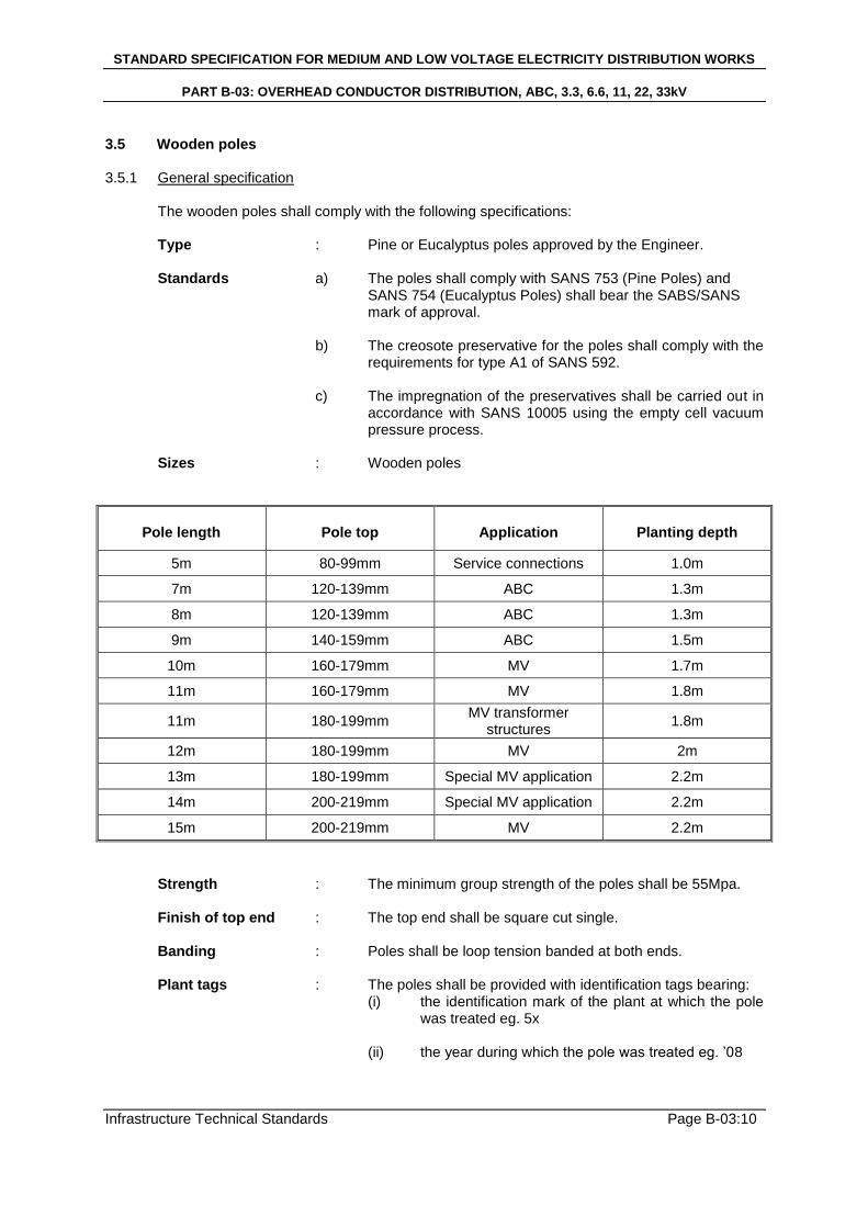
3.5 Wooden poles 3.5.1 General specification
The wooden poles shall comply with the following specifications: Type : Pine or Eucalyptus poles approved by the Engineer. Standards a) The poles shall comply with SANS 753 (Pine Poles) and SANS 754 (Eucalyptus Poles) shall bear the SABS/SANS
mark of approval.
b) The creosote preservative for the poles shall comply with the requirements for type A1 of SANS 592.
c) The impregnation of the preservatives shall be carried out in
accordance with SANS 10005 using the empty cell vacuum pressure process.
Sizes : Wooden poles
Pole length
Pole top
Application
Planting depth
5m 80-99mm Service connections 1.0m
7m 120-139mm ABC 1.3m
8m 120-139mm ABC 1.3m
9m 140-159mm ABC 1.5m
10m 160-179mm MV 1.7m
11m 160-179mm MV 1.8m
11m 180-199mm MV transformer
structures 1.8m
12m 180-199mm MV 2m
13m 180-199mm Special MV application 2.2m
14m 200-219mm Special MV application 2.2m
15m 200-219mm MV 2.2m
Strength : The minimum group strength of the poles shall be 55Mpa. Finish of top end : The top end shall be square cut single. Banding : Poles shall be loop tension banded at both ends. Plant tags : The poles shall be provided with identification tags bearing:
(i) the identification mark of the plant at which the pole was treated eg. 5x
(ii) the year during which the pole was treated eg. ‟08
STANDARD SPECIFICATION FOR MEDIUM AND LOW VOLTAGE ELECTRICITY DISTRIBUTION WORKS
PART B-03: OVERHEAD CONDUCTOR DISTRIBUTION, ABC, 3.3, 6.6, 11, 22, 33kV
Infrastructure Technical Standards Page B-03:11
(iii) the class of wood preservative used (see SANS
10005) eg. A1
(iv) the number of the charge in which the pole was treated eg. 137
(v) the group strength or maximum fibre stress in bending eg. 55Mpa.
Drilling of poles : Templates shall be used for drilling holes required to fix
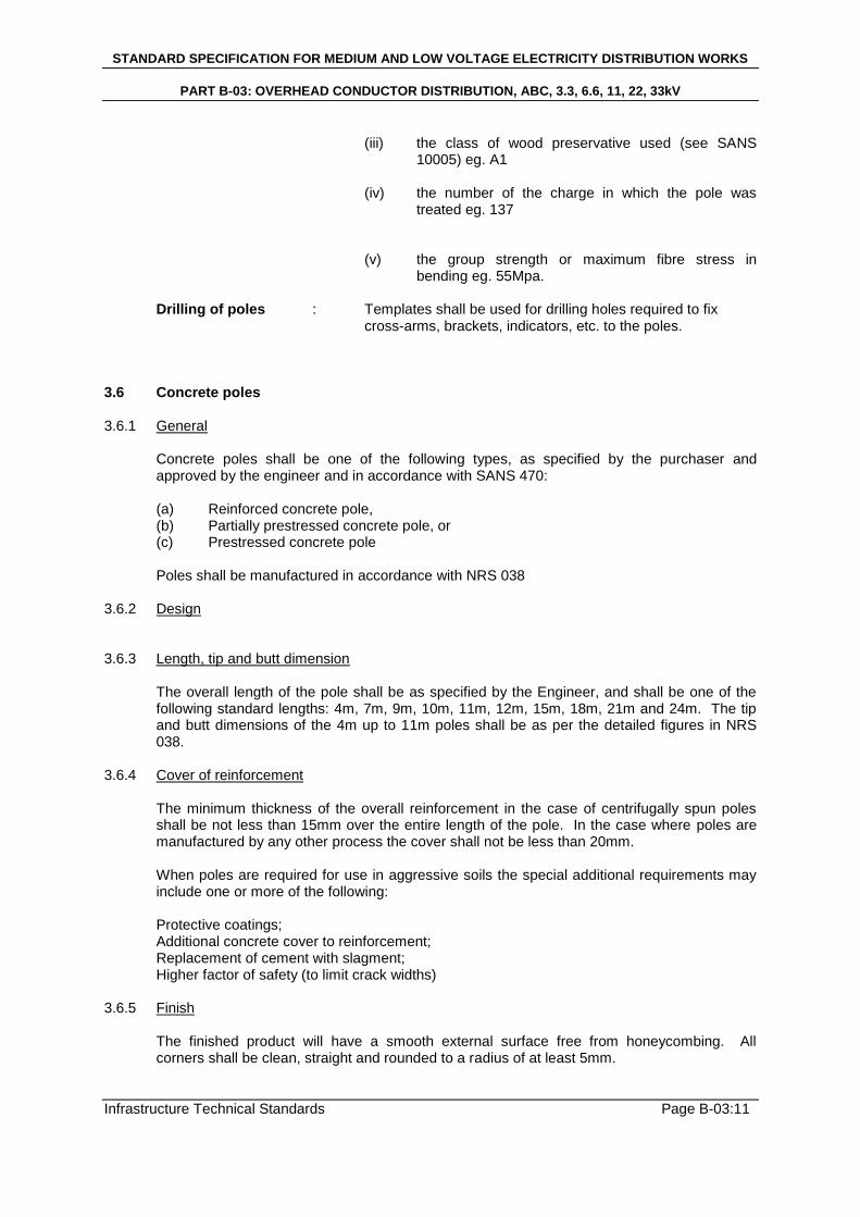
cross-arms, brackets, indicators, etc. to the poles. 3.6 Concrete poles 3.6.1 General
Concrete poles shall be one of the following types, as specified by the purchaser and approved by the engineer and in accordance with SANS 470: (a) Reinforced concrete pole, (b) Partially prestressed concrete pole, or (c) Prestressed concrete pole
Poles shall be manufactured in accordance with NRS 038
3.6.2 Design 3.6.3 Length, tip and butt dimension
The overall length of the pole shall be as specified by the Engineer, and shall be one of the following standard lengths: 4m, 7m, 9m, 10m, 11m, 12m, 15m, 18m, 21m and 24m. The tip and butt dimensions of the 4m up to 11m poles shall be as per the detailed figures in NRS 038.
3.6.4 Cover of reinforcement
The minimum thickness of the overall reinforcement in the case of centrifugally spun poles shall be not less than 15mm over the entire length of the pole. In the case where poles are manufactured by any other process the cover shall not be less than 20mm. When poles are required for use in aggressive soils the special additional requirements may include one or more of the following: Protective coatings; Additional concrete cover to reinforcement; Replacement of cement with slagment; Higher factor of safety (to limit crack widths)
3.6.5 Finish
The finished product will have a smooth external surface free from honeycombing. All corners shall be clean, straight and rounded to a radius of at least 5mm.
STANDARD SPECIFICATION FOR MEDIUM AND LOW VOLTAGE ELECTRICITY DISTRIBUTION WORKS
PART B-03: OVERHEAD CONDUCTOR DISTRIBUTION, ABC, 3.3, 6.6, 11, 22, 33kV
Infrastructure Technical Standards Page B-03:12
3.6.6 Holes
Holes shall be provided in the poles during the manufacturing of the poles. These holes shall be used for the attachment of strain or suspension and other equipment. The holes shall be positioned as specified in the relevant figures detailed in NRS 038. Drawings indicating the specified poles with pole holes shall be furnished to the Engineer for approval prior to ordering thereof. On all transformer poles, the integral earthing facility EW 2900 and EW 8700 shall be replaced with a PVC conduit embedded in the concrete to protect the earth conductor in order to allow for separate earthing of the MV and LV earth in accordance with SANS 10292 and SANS 10200 respectively. This separate earthing is necessary when the earth resistivity value of the transformer structure is above 1 ohm. On all other MV poles the earthing ferrules (EW 2200 and EW 8000) shall be provided for earthing of the poles.
3.6.7 Pole Strength
Pole strengths shall comply to table 1, NRS 038 and SANS 470. 3.7 Monopole Steel Structures 3.7.1 Design
All steel structures shall be manufactured in accordance with industry standards and ISO certifications in accordance with SANS 121. Steel structures shall be galvanised in order to protect the structure from corrosion.
3.7.2 Paint and Finishing Painting and finishing shall be in accordance with BS 2569 and SANS 1091. Where the galvanised coating has been damaged during erection and after all assemblies have been attached to the structure, zinc metal paint in accordance with BS 2569 shall be applied to the areas for protection against corrosion.
STANDARD SPECIFICATION FOR MEDIUM AND LOW VOLTAGE ELECTRICITY DISTRIBUTION WORKS
PART B-03: OVERHEAD CONDUCTOR DISTRIBUTION, ABC, 3.3, 6.6, 11, 22, 33kV
Infrastructure Technical Standards Page B-03:13
4 STAY ASSEMBLIES 4.1 General
(a) The position of stays may or may not be indicated on the drawings or in the site instructions to be issued, but it is the responsibility of the Contractor to provide staying adequate to maintain correct tension of the line and the verticality of every pole in the line. Stay assemblies shall conform to NRS 022 and NRS 051.
(b) Struts and fly stays shall only be installed where it is not possible to install a stay.
(c) Stay wires shall be installed with approved preformed materials.
(d) The angle between the stay and the poles shall be between 30 and 45 degrees. The
stay must be made off on the pole, as near as practical to the point of resultant stress.
(e) For terminal poles of vertical arrangements (eg. MV line on top and LV line below), at
least two stays shall be used to prevent deformation of the pole, with the stay plates buried at least 1.8m apart.
4.2 Staywire 4.2.1 General
Stay wires shall comply with SANS 182-5 and shall be manufactured from zinc-coated stranded steel wires. Generally stay wires shall be galvanized steel strand of the type with BS 183 Grade 700. Strength shall be a minimum of 450kPa for both MV and LV line stays. Stay wires and their associated fittings shall be tested in the manner specified for conductors, and the breaking load shall not be less than 95% of the stay wire breaking load. Any deviation from the above required stay wires strand sizes shall be determined in accordance with SANS 185-5. Thimbles shall be used with guy grips to support wired through the stay-rod eye. A combination of guy grips and pole top make offs shall be used as indicated in the drawings.
4.2.2 Stay wire for MV line
The number and standard diameter of wires shall be 7 /4.00mm or nearest complying with 450 kPa. The overall diameter shall be 12.19mm (min.) in accordance with SANS 182-5.
4.2.3 Stay wire for LV line
The number and standard diameter of wires shall be 5 /4.00mm or nearest complying with 450 kPa. The overall diameter shall be 10.97mm (min.) in accordance with SANS 182-5.
4.3 Stay rod
Stay rods for LV installations shall be 12mm in diameter and 1500mm long, for MV installations the stay rod shall be 16mm in diameter and 2000mm long. Both MV and LV stay rods shall be non-adjustable. Stay rod sizes may be reduced as long as compliance to 450kPa strength is maintained.
STANDARD SPECIFICATION FOR MEDIUM AND LOW VOLTAGE ELECTRICITY DISTRIBUTION WORKS
PART B-03: OVERHEAD CONDUCTOR DISTRIBUTION, ABC, 3.3, 6.6, 11, 22, 33kV
Infrastructure Technical Standards Page B-03:14
Stay rods may not be bent when installed in sandy soil conditions, special permission must be acquired from the Engineer to bend the rods i.e. in hard rock conditions where stay rod holes were drilled. Cold bending of stay rods shall not be acceptable. Coastal and corrosive environments may require sleeving and extra material according to required specifications, for the protection of stay rods and stay plates.
4.4 Stay rod base plate 4.4.1 Base plate for MV line stay rod
Stay rod base plates shall be 350mm x 350mm x 6mm hot dipped galvanized steel. Base plates may be cut round to a diameter 375mm or octagonal to a width of at least 375mm, but shall after being cut still be galvanized to SANS 935 and BS 2569 standards.
4.4.2 Base plate for LV line stay rod
Stay rod base plates shall be 300mm x 300mm x 6mm hot dipped galvanized steel. Base plate may be cut round to a diameter of 300mm or octagonal to a width of at least 300mm, but shall after being cut still be galvanized to SANS 935 and BS 2569 standards.
4.5 Preformed stay fittings 4.5.1 General
All material used for the stay work shall be galvanized. The minimum number and size of stays shall be used with each type of line support. All stays shall be taken down at an angle to the pole of approximately 30-45 degrees consistent with adequate stay tension.
4.5.2 Pole top make off
Pole top make off - galvanized guy grip pole top dead end – double wire guy grip, complete to SANS specifications for pole diameter of 130mm to 200mm. LV pole top make off shall be approved by the Engineer. MV pole top make off shall be approved by the Engineer.
4.5.3 Preformed guy grips
Preformed galvanized steel guy grip with thimble and stay insulator dead ends shall be used. LV stay guy grips shall be approved by the engineer in accordance with NRS 053. MV stay guy grips shall be approved by the engineer in accordance with NRS 053.
4.6 Stay insulator
In each MV stay assembly, a fully glazed porcelain stay insulator having minimum W.F.O. of 30kV shall be fitted. The MV stay insulator shall be of the 100kN type for 7 /4.00mm stay wire and of the 34kN type for 5 /4.00mm LV stay assemblies, where specified, and shall be in accordance with NRS 022. Glass fibre rod stay insulator of the 100kN type may be used instead of the fully glazed porcelain insulator on MV stay assemblies. Porcelain insulators shall not be installed upside down.
STANDARD SPECIFICATION FOR MEDIUM AND LOW VOLTAGE ELECTRICITY DISTRIBUTION WORKS
PART B-03: OVERHEAD CONDUCTOR DISTRIBUTION, ABC, 3.3, 6.6, 11, 22, 33kV
Infrastructure Technical Standards Page B-03:15
4.7 Stay guards
(a) Because stays are vulnerable to mechanical damage and be a danger to pedestrians and traffic, all stays in the vicinity of public paths and roadways shall be fitted with stay guards.
(b) Where a stay is very exposed to traffic, these guards shall be 2m long (minimum)
wooden poles of minimum diameter 120mm, buried to a minimum depth of 1m and protruding at least 1m out of the ground. The exposed part shall be painted yellow road marking paint. Arrangement of stay guards shall be such that the stay is adequately protected.
(c) On less vulnerable stays, a stay warning pipe will be sufficient. These stay guards
should enclose the stay wire from the top of the stay rod ±2m above ground and should have a minimum diameter of 32mm. Stay warning pipes shall be painted a bright yellow colour with black stripes to be easily visible during day or night time. A cable clamp shall be fitted to the stay wire above the warning pipe to prevent any sliding of the pipe along the stay wire. The thread of the cable clamp shall be damaged after installation.
(d) Where the stay wire passes between low voltage conductors the stay wire must be
insulated with a plastic sleeve and clamped at the ends. 4.8 Other stay accessories 4.8.1 Cable clamps
Galvanized cable clamps suitable for use with a double 9.75mm and 10.97mm diameter stay wire shall be supplied and installed.
4.8.2 Eye-bolt assembly
M20 x 250mm eyebolt with 240mm thread connected, complete with 2 curved washers, 60 x 60 x 2 washers, spring washers and hexagonal nuts. Minimum breaking load shall be greater than 60kN.
STANDARD SPECIFICATION FOR MEDIUM AND LOW VOLTAGE ELECTRICITY DISTRIBUTION WORKS
PART B-03: OVERHEAD CONDUCTOR DISTRIBUTION, ABC, 3.3, 6.6, 11, 22, 33kV
Infrastructure Technical Standards Page B-03:16
5 EXCAVATION 5.1 General
(a) Rates for excavation shall include all labour, tools and plant, refilling and compacting, restoration of surfaces, removal or surplus material, bearing in mind the possible need to re-instate existing facilities where these are damaged and hire a registered land surveyor to calculate the position and to replace any surveyed pegs removed in the process of excavation or refilling.
(b) Rates shall also include, where necessary, timbering and shoring.
(c) In case where more than one billed rate is applicable to any single excavation, or to a
group of such excavations, the quantity or excavation at each separate rate shall be measured and form the basis for payment. The Engineer may, however, in his discretion, determine an intermediate rate based on the average proportion of each applicable rate and may use such intermediate rate for evaluation of the prices of such excavation.
(d) Tenders shall be based on billed quantities and any variations shall be measured on
site during the course of excavation work.
(e) The contractor shall advise the Engineer before backfilling excavations, to enable the Engineer to determine the applicable rates. Sufficient notice shall be given to the Engineer to enable the Engineer to arrange a visit to site to determine the applicable rates.
(f) The soil type shall be identified and classified in accordance with project
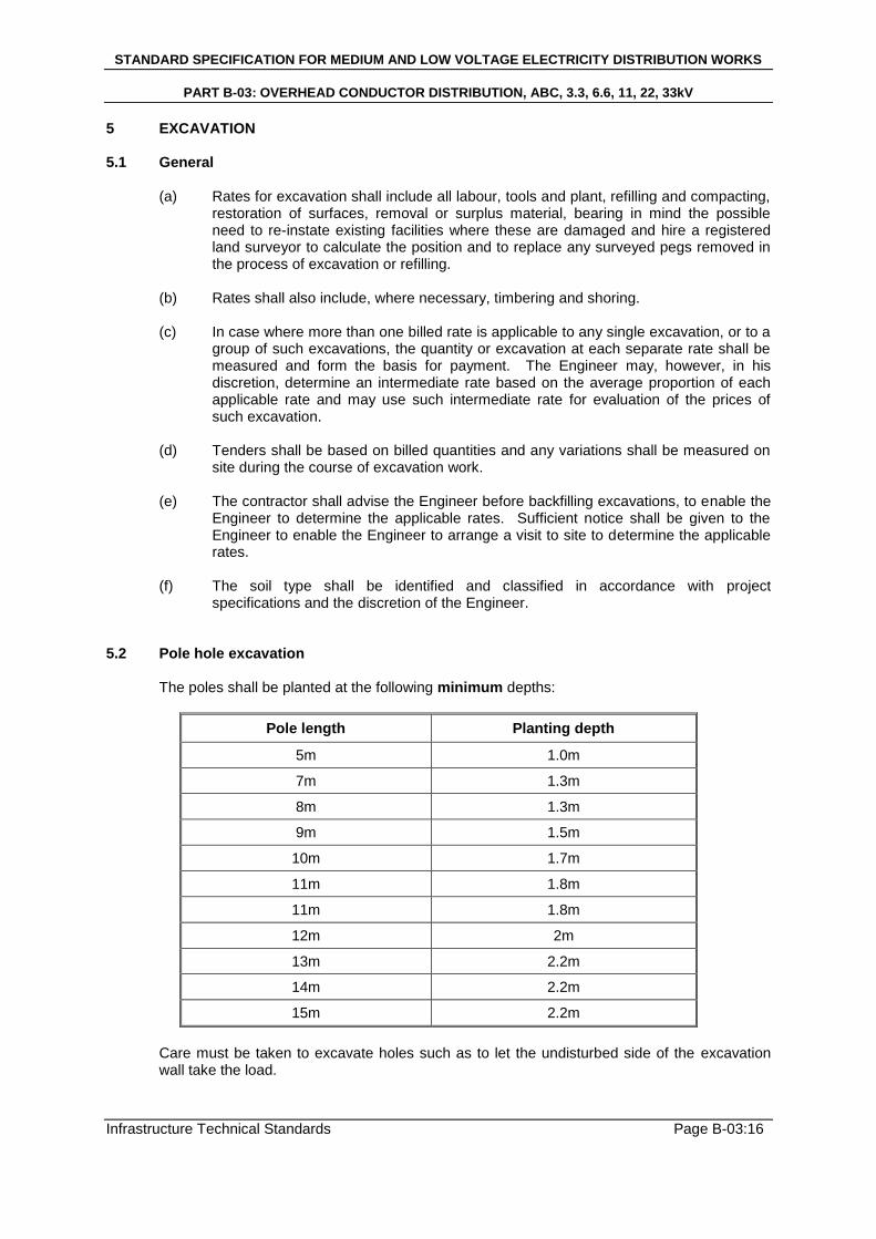
specifications and the discretion of the Engineer. 5.2 Pole hole excavation
The poles shall be planted at the following minimum depths:
Pole length Planting depth
5m 1.0m
7m 1.3m
8m 1.3m
9m 1.5m
10m 1.7m
11m 1.8m
11m 1.8m
12m 2m
13m 2.2m
14m 2.2m
15m 2.2m
Care must be taken to excavate holes such as to let the undisturbed side of the excavation wall take the load.
STANDARD SPECIFICATION FOR MEDIUM AND LOW VOLTAGE ELECTRICITY DISTRIBUTION WORKS
PART B-03: OVERHEAD CONDUCTOR DISTRIBUTION, ABC, 3.3, 6.6, 11, 22, 33kV
Infrastructure Technical Standards Page B-03:17
5.3 Stay hole excavation
Stay holes shall be vertical, not less than 1.5m deep and no wider than necessary to accommodate the base plate, with a narrow side channel cut to embed the rod at the correct angle. The base plate and portion of rod within the stay hole shall be firmly packed with hard material, soilcrete or grout in accordance with design specifications and approval of the Engineer.
5.4 Compacting of holes
(a) The soil used for backfilling the hole after the pole has been planted shall be slightly damped for good compaction purposes.
(b) When filling up a hole, layers of 300mm soil shall be added at intervals and
compacted with a mechanical compactor or with a hand-stomper, weighing more or less 25kg.
(c) Proper compacting of the ground around a pole is essential and may be achieved
with a 1:10 cement/sand mixture (soilcrete) for the backfill. 5.5 Rock Anchors
Rock anchors shall be utilised in areas of soft and hard rock. Rock anchors shall be 1500mm long by 12mm in diameter at 450kPa. Anchors are installed utilising drilling machinery and high pressure grouting cement.
STANDARD SPECIFICATION FOR MEDIUM AND LOW VOLTAGE ELECTRICITY DISTRIBUTION WORKS
PART B-03: OVERHEAD CONDUCTOR DISTRIBUTION, ABC, 3.3, 6.6, 11, 22, 33kV
Infrastructure Technical Standards Page B-03:18
6 LINE CONFIGURATION 6.1 General 6.1.1 Galvanizing
Except where specified to the contrary, all iron and steel used in the construction of the Contract Works shall be galvanized in accordance with SANS 121 after all sawing, shearing, drilling, punching, filling, bedding and machining are completed. Galvanizing shall be applied by the hot process (except the electro-galvanizing shall be permissible for steel wires), and for all parts other than steel wires shall consist of a suitable thickness of zinc coated or not less than 0.61kg/m
2 of surface. The zinc shall be smooth, clean, or uniform thickness and free
from defects. The preparation for galvanizing and the galvanizing itself shall not adversely affect the mechanical properties of the coated material.
6.1.2 Bolts and nuts
All metal parts shall be secured by means of bolts and nuts whose minimum diameter shall be 12mm. All bolts, nuts and screw threads shall comply with SABS 135 (there is no SANS equivalent) and galvanized in accordance with SANS 121 unless otherwise approved. Bolts and nuts shall be of steel with hexagonal heads. The nuts of all bolts for attaching to the tower plats, brackets or angles supporting insulator sets or droppers to earth conductor clamps shall be locked by approved means. No screwed threads shall form part of the shearing plane between members. Unless otherwise approved, all bolts and screwed rods shall be galvanized including the threaded portions; all nuts shall be galvanized with the exception of the threads, which shall be greased. When in position all bolts or screwed rods shall project through corresponding nuts, but such projection shall not exceed the diameter of the actual bolt. Where different grades of steel are used, bolts of any given diameter and length shall conform to the same grade of steel.
6.2 A-frame configuration 6.2.1 Strain A-frame
A-frames shall be manufactured from mild steel standard profiles as per NamPower Specification and drawings. A-frames shall be completely bolted to pole with two M20 x 200 bolts threaded 80mm, or threaded rod, complete with curved washers, spring washers and hexagonal nuts and locknuts. All holes drilled on A-frame to 22mm diameter.
STANDARD SPECIFICATION FOR MEDIUM AND LOW VOLTAGE ELECTRICITY DISTRIBUTION WORKS
PART B-03: OVERHEAD CONDUCTOR DISTRIBUTION, ABC, 3.3, 6.6, 11, 22, 33kV
Infrastructure Technical Standards Page B-03:19
6.2.2 Intermediate A-frame
A-frames shall be manufactured from mild steel standard profiles as per NamPower specification. Frames shall be completely bolted to pole with 2 off M20 x 200 bolts threaded 80mm, or threaded rod, complete with curved washers, spring washers and hexagonal nuts and locknuts. All holes drilled to 22mm diameter.
6.3 Vertical staggered delta configuration 6.3.1 Strain Staggered Delta
Longrod insulators with thimble clevis in accordance with the standards referenced in section 1 shall be used and installed in accordance with approved Engineering detailed drawings. Minimum clearance between insulators shall be 600mm. Insulators shall be bolted to the pole using M20 x 250 Eye Bolts, complete with curved washers, spring washers and hexagonal nuts and locknuts. All holes drilled on structure to be 22mm.
6.3.2 Intermediate Staggered Delta
Longrod insulators with thimble clevis in accordance with the standards referenced in section 1 shall be used and installed in accordance with approved Engineering detailed drawings. Minimum clearance between insulators shall be 600mm. Insulators shall be bolted to the pole using M20 x 250 Eye Bolts, complete with curved washers, spring washers and hexagonal nuts and locknuts. All holes drilled on structure to be 22mm.
STANDARD SPECIFICATION FOR MEDIUM AND LOW VOLTAGE ELECTRICITY DISTRIBUTION WORKS
PART B-03: OVERHEAD CONDUCTOR DISTRIBUTION, ABC, 3.3, 6.6, 11, 22, 33kV
Infrastructure Technical Standards Page B-03:20
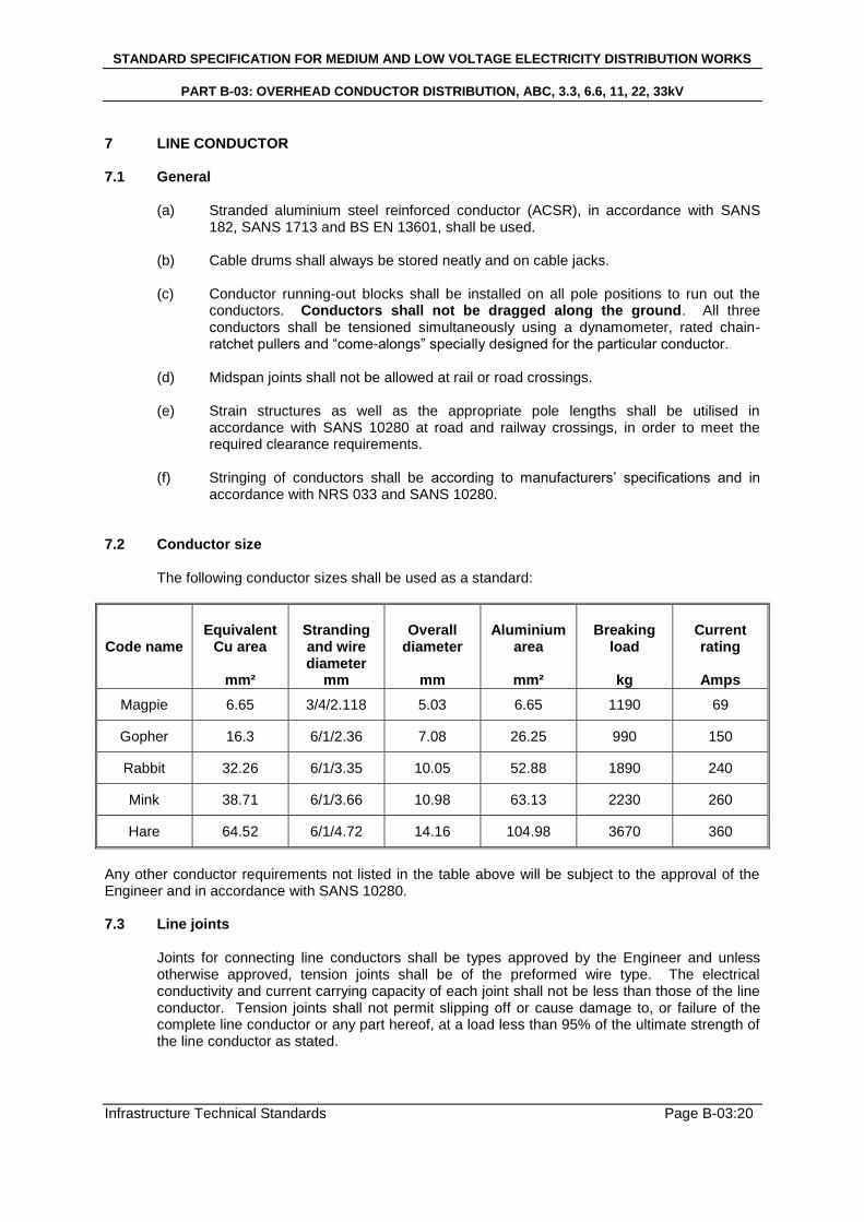
7 LINE CONDUCTOR 7.1 General
(a) Stranded aluminium steel reinforced conductor (ACSR), in accordance with SANS 182, SANS 1713 and BS EN 13601, shall be used.
(b) Cable drums shall always be stored neatly and on cable jacks.
(c) Conductor running-out blocks shall be installed on all pole positions to run out the
conductors. Conductors shall not be dragged along the ground. All three conductors shall be tensioned simultaneously using a dynamometer, rated chain-ratchet pullers and “come-alongs” specially designed for the particular conductor.
(d) Midspan joints shall not be allowed at rail or road crossings. (e) Strain structures as well as the appropriate pole lengths shall be utilised in
accordance with SANS 10280 at road and railway crossings, in order to meet the required clearance requirements.
(f) Stringing of conductors shall be according to manufacturers‟ specifications and in
accordance with NRS 033 and SANS 10280. 7.2 Conductor size
The following conductor sizes shall be used as a standard:
Code name
Equivalent
Cu area
mm²
Stranding and wire diameter
mm
Overall
diameter
mm
Aluminium
area
mm²
Breaking
load
kg
Current rating
Amps
Magpie 6.65 3/4/2.118 5.03 6.65 1190 69
Gopher 16.3 6/1/2.36 7.08 26.25 990 150
Rabbit 32.26 6/1/3.35 10.05 52.88 1890 240
Mink 38.71 6/1/3.66 10.98 63.13 2230 260
Hare 64.52 6/1/4.72 14.16 104.98 3670 360
Any other conductor requirements not listed in the table above will be subject to the approval of the Engineer and in accordance with SANS 10280. 7.3 Line joints
Joints for connecting line conductors shall be types approved by the Engineer and unless otherwise approved, tension joints shall be of the preformed wire type. The electrical conductivity and current carrying capacity of each joint shall not be less than those of the line conductor. Tension joints shall not permit slipping off or cause damage to, or failure of the complete line conductor or any part hereof, at a load less than 95% of the ultimate strength of the line conductor as stated.
STANDARD SPECIFICATION FOR MEDIUM AND LOW VOLTAGE ELECTRICITY DISTRIBUTION WORKS
PART B-03: OVERHEAD CONDUCTOR DISTRIBUTION, ABC, 3.3, 6.6, 11, 22, 33kV
Infrastructure Technical Standards Page B-03:21
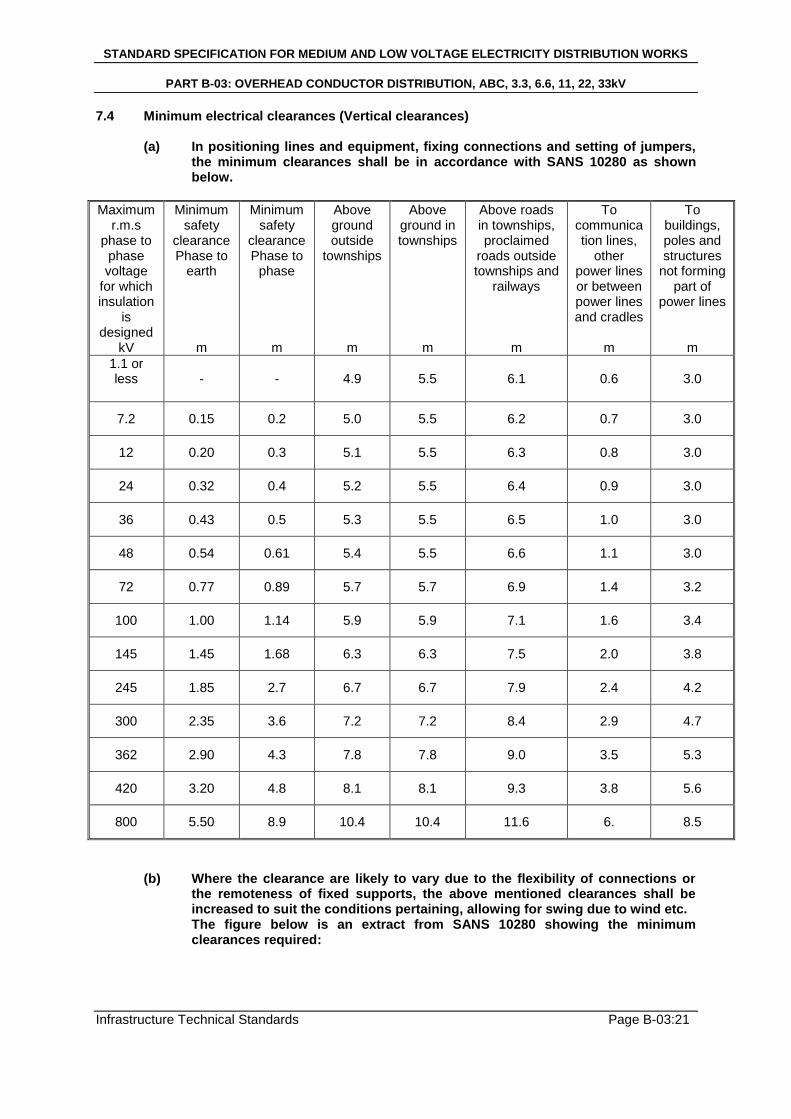
7.4 Minimum electrical clearances (Vertical clearances)
(a) In positioning lines and equipment, fixing connections and setting of jumpers, the minimum clearances shall be in accordance with SANS 10280 as shown below.
Maximum r.m.s
phase to phase voltage
for which insulation
is designed
kV
Minimum safety
clearance Phase to
earth
m
Minimum safety
clearance Phase to
phase
m
Above ground outside
townships
m
Above ground in townships
m
Above roads in townships, proclaimed
roads outside townships and
railways
m
To communication lines,
other power lines or between power lines and cradles
m
To buildings, poles and structures
not forming part of
power lines
m
1.1 or less
- - 4.9 5.5 6.1 0.6 3.0
7.2 0.15 0.2 5.0 5.5 6.2 0.7 3.0
12 0.20 0.3 5.1 5.5 6.3 0.8 3.0
24 0.32 0.4 5.2 5.5 6.4 0.9 3.0
36 0.43 0.5 5.3 5.5 6.5 1.0 3.0
48 0.54 0.61 5.4 5.5 6.6 1.1 3.0
72 0.77 0.89 5.7 5.7 6.9 1.4 3.2
100 1.00 1.14 5.9 5.9 7.1 1.6 3.4
145 1.45 1.68 6.3 6.3 7.5 2.0 3.8
245 1.85 2.7 6.7 6.7 7.9 2.4 4.2
300 2.35 3.6 7.2 7.2 8.4 2.9 4.7
362 2.90 4.3 7.8 7.8 9.0 3.5 5.3
420 3.20 4.8 8.1 8.1 9.3 3.8 5.6
800 5.50 8.9 10.4 10.4 11.6 6. 8.5
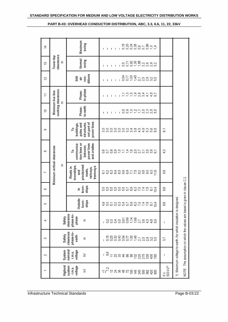
(b) Where the clearance are likely to vary due to the flexibility of connections or the remoteness of fixed supports, the above mentioned clearances shall be increased to suit the conditions pertaining, allowing for swing due to wind etc. The figure below is an extract from SANS 10280 showing the minimum clearances required:
STANDARD SPECIFICATION FOR MEDIUM AND LOW VOLTAGE ELECTRICITY DISTRIBUTION WORKS
PART B-03: OVERHEAD CONDUCTOR DISTRIBUTION, ABC, 3.3, 6.6, 11, 22, 33kV
Infrastructure Technical Standards Page B-03:22
STANDARD SPECIFICATION FOR MEDIUM AND LOW VOLTAGE ELECTRICITY DISTRIBUTION WORKS
PART B-03: OVERHEAD CONDUCTOR DISTRIBUTION, ABC, 3.3, 6.6, 11, 22, 33kV
Infrastructure Technical Standards Page B-03:23
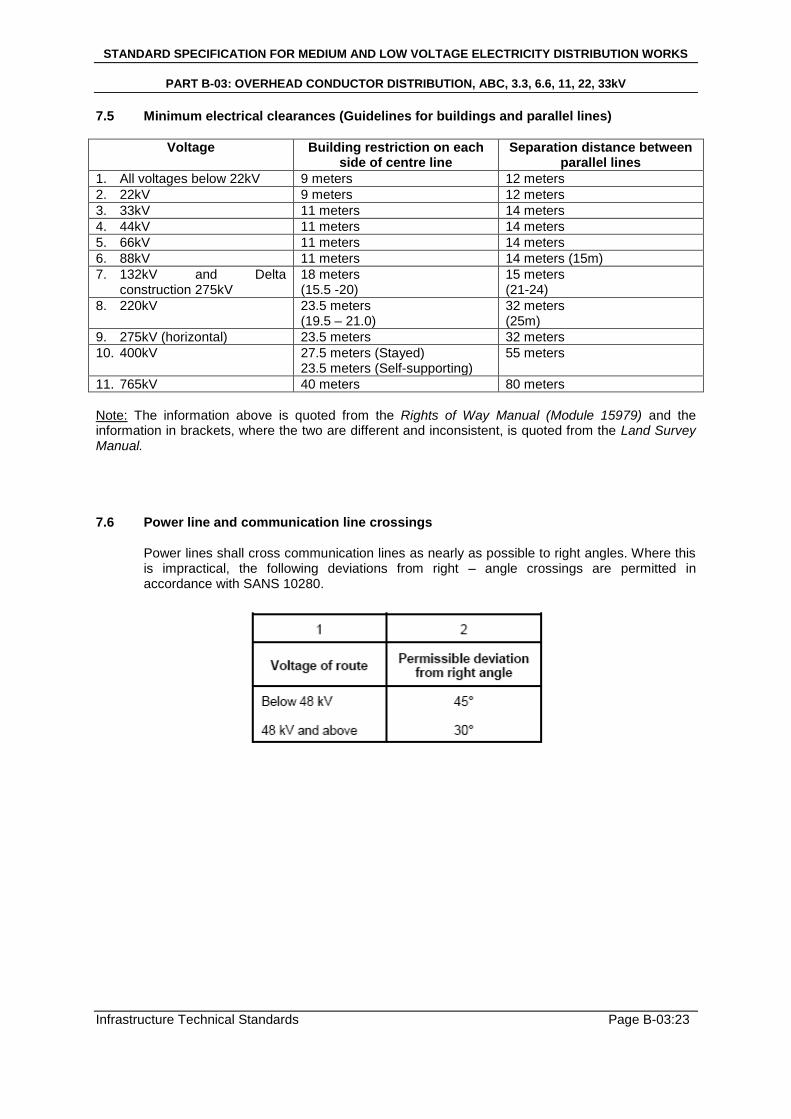
7.5 Minimum electrical clearances (Guidelines for buildings and parallel lines)
Voltage Building restriction on each side of centre line
Separation distance between parallel lines
1. All voltages below 22kV 9 meters 12 meters
2. 22kV 9 meters 12 meters
3. 33kV 11 meters 14 meters
4. 44kV 11 meters 14 meters
5. 66kV 11 meters 14 meters
6. 88kV 11 meters 14 meters (15m)
7. 132kV and Delta construction 275kV
18 meters (15.5 -20)
15 meters (21-24)
8. 220kV 23.5 meters (19.5 – 21.0)
32 meters (25m)
9. 275kV (horizontal) 23.5 meters 32 meters
10. 400kV 27.5 meters (Stayed) 23.5 meters (Self-supporting)
55 meters
11. 765kV 40 meters 80 meters
Note: The information above is quoted from the Rights of Way Manual (Module 15979) and the information in brackets, where the two are different and inconsistent, is quoted from the Land Survey Manual. 7.6 Power line and communication line crossings
Power lines shall cross communication lines as nearly as possible to right angles. Where this is impractical, the following deviations from right – angle crossings are permitted in accordance with SANS 10280.
STANDARD SPECIFICATION FOR MEDIUM AND LOW VOLTAGE ELECTRICITY DISTRIBUTION WORKS
PART B-03: OVERHEAD CONDUCTOR DISTRIBUTION, ABC, 3.3, 6.6, 11, 22, 33kV
Infrastructure Technical Standards Page B-03:24
8 INSULATORS 8.1 General 8.1.1 Types of insulators
Long rod, Class A insulators shall be used at all cross arms for medium voltage strain, terminal and pole mounted transformer structures. The cycloaliphatic long rod or porcelain insulator shall be puncture proof and of the type as specified in design Detail Specifications as approved by the Engineer. The end fitted attachment shall be of the aluminium alloy clevis and tongue twisted type. The insulator shed material shall have a high resistance to tracking by surface leakage currents and operate normally under adverse weather conditions. All insulators shall conform to the standards referenced in section 1. Line post type insulators shall be installed on straight line structures and the insulating material shall be a cycloaliphatic resin or porcelain complete with 20mm spindle including nuts and washers. Line post insulators shall furthermore be of the capless, solid-core type, be puncture proof, radio interference free and shall display superior performance in polluted environments. They shall have a basic insulation level of either 135kV or 150kV as specified in the Detail Specification in accordance with standards and the approval of the Engineer. All standards referenced in section 1 shall be adhered to. Glass type insulators shall where possible not be used due to vandalism. However glass insulators can be used if the Supply Authority feels it necessary and is in accordance with the standards listed in section 1. Glass insulators are permitted in coastal regions up to 40 km in land from the coastal region, due to corrosion and heavy pollution.
8.1.2 Electrical design
Insulators together with their fittings shall comply with SANS 60305, SANS 60383, BS EN 60305, BS 3288 and IEC 1109 and shall offer a high resistance to damage, caused by malicious vandalism. Insulator material shall be cycloalipohatic resin. As an alternative high grade porcelain insulators shall be used. The flashover and puncture voltages shall not be less than the values stated in the table below. Insulator flashover voltage, wet and dry, shall be less than the puncture voltage. Shackle insulators shall be used on all low voltage overhead conductors. The shackle insulators suitable for mounting to the pole with a D-bracket shall be of the type specified in the Project Detail Specification in accordance with the Engineer.
8.1.3 Mechanical design
The strength of the insulator shall be such that at the maximum working load of 4kN for line post insulators and 40kN for strain insulators shall be afforded.
8.1.4 Clamps and conductor fittings
Tension conductor clamps shall be of types approved by the Engineer and shall be as light as possible, and shall be designed to avoid any possibility of deforming the stranded conductor and separating the individual strands.
All fittings shall comply with the stranded coupling dimensions specified in the standards listed in section 1.
STANDARD SPECIFICATION FOR MEDIUM AND LOW VOLTAGE ELECTRICITY DISTRIBUTION WORKS
PART B-03: OVERHEAD CONDUCTOR DISTRIBUTION, ABC, 3.3, 6.6, 11, 22, 33kV
Infrastructure Technical Standards Page B-03:25
Intermediate pole conductor binding shall be carried out by means of wrap lock ties complete with neoprene cover. Tension fittings shall be the preformed wire type, specially designed for the ACSR conductor used together with suitable fittings for securing the tension insulators. Tension insulator sets and fittings shall be approved by the Engineer to give the minimum required clearances between the jumper conductor and the rim of the live end insulator units. Adequate bearing area between fittings shall be provided and „point‟ or „line‟ contacts shall be avoided. All split pins for securing the attachment of fittings of insulator sets shall be of stainless steel type material and shall be backed by washers. D-shackles between insulator and eye shall be installed at all strain positions in accordance with SANS 10280.
8.2 Strain insulators
Strain insulators of the twisted clevis tongue type are required for strain and terminal poles. The insulators shall be cycloaliphatic resin or high grade porcelain material as specified in the detailed project specification and approved by the Engineer. Strain insulators shall be complete with galvanized clevis pin (to SANS 121) c/w washer and stainless steel split pin (304 s/steel), for preformed dead end. Strain insulators shall be installed and connected to cross-arms and A-frames, with D- shackles, clevis thimble and preformed dead end for conductor as per design specifications. 11kV 22kV 33kV Nominal voltage 11kV 22kV 33kV Impulse withstand (Minimum) 120kV 150kV 180kV Mechanical strength (Minimum) 70kN 70kN 70kN
8.2.1 Porcelain disc insulator
High grade porcelain, 70kN mechanical strength. Nominal voltage – 11kV, 22kV or 33kV as specified and approved by the Engineer.
8.2.2 Long rod insulator
Cycloaliphatic long rod, min. failing load 70kN, with clevis tongue twisted arrangement with corrosion resistant end caps, complete with galvanized clevis pin (to SANS 121) c/w washer and stainless steel split pin (304 s/steel), preformed dead end type for conductor size as specified – nominal voltage of 11kV, 22kV or 33 kV as specified.
8.3 Intermediate insulators
Line post insulators are required for the intermediate poles on A-frames and for staggered vertical delta configurations. Complete installed and connected to A-frame, with spindles or on poles c/w spindles, curved washer (50 x 50), spring washer and nut as specified by NamPower. A-frame mounting: Short spindle – Type M2 threaded to 44mm complete with washer, nut and locknut, for mounting bracket, complete with line tie for specified the specified conductor. Pole-mounting: long spindle – Type M2 with 178mm shank threaded to 100mm, 250mm for mounting through pole, c/w curved washer (50 x 50), spring washer and nut. Complete with line tie for specified conductor.
STANDARD SPECIFICATION FOR MEDIUM AND LOW VOLTAGE ELECTRICITY DISTRIBUTION WORKS
PART B-03: OVERHEAD CONDUCTOR DISTRIBUTION, ABC, 3.3, 6.6, 11, 22, 33kV
Infrastructure Technical Standards Page B-03:26
8.3.1 Porcelain line post insulator
High grade porcelain for 11kV, 22kV or 33kV, 4kN lateral mechanical strength. Complete installed with line ties for specified conductor.
8.3.2 Cycloaliphatic line post insulator
For A-frame mounting cycloaliphatic line post insulator – cantilever failing load 4kN, for M20 spindle – for 11kV and 22kV as specified.
All insulators and equipment shall conform to the requirements stipulated in the standards referenced for insulators in section 1.
STANDARD SPECIFICATION FOR MEDIUM AND LOW VOLTAGE ELECTRICITY DISTRIBUTION WORKS
PART B-03: OVERHEAD CONDUCTOR DISTRIBUTION, ABC, 3.3, 6.6, 11, 22, 33kV
Infrastructure Technical Standards Page B-03:27
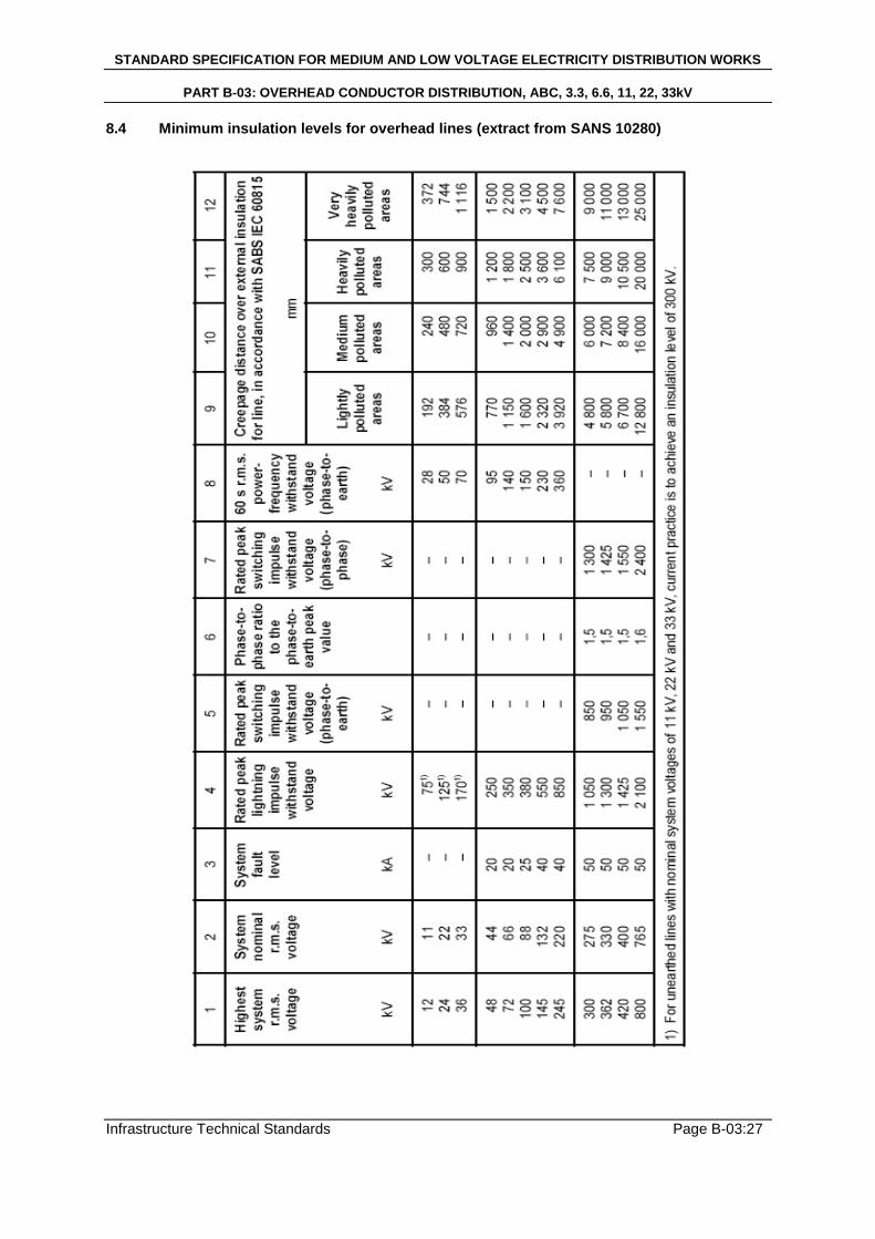
8.4 Minimum insulation levels for overhead lines (extract from SANS 10280)
STANDARD SPECIFICATION FOR MEDIUM AND LOW VOLTAGE ELECTRICITY DISTRIBUTION WORKS
PART B-03: OVERHEAD CONDUCTOR DISTRIBUTION, ABC, 3.3, 6.6, 11, 22, 33kV
Infrastructure Technical Standards Page B-03:28
9 LINE FITTINGS
9.1 Preformed binding ties
The binding ties shall be preformed wrap lock or side ties with pad for ACSR, for the specified pin and linepost insulators, as required and detailed in the design specifications and approved by the Engineer.
9.2 Preformed dead ends
The preformed dead ends shall be suitable for the size ACSR used and shall be verified by the Engineer in accordance with the design specifications.
9.3 Thimble clevis
Complete with stainless steel split pin (Grade 403), and galvanized pin and washer. Thimble clevis shall be Suitable for specified conductor and approved by the Engineer in accordance with the design specifications.
9.4 Parallel groove clamps
The parallel groove clamps shall be suitable for making electrical connections to aluminium or copper conductors providing a current carrying capacity suitable for conductor size. A two bolt PG clamp is required. Bi-metallic PG clamps shall be used when copper to aluminium connections is made. All equipment shall be approved by the Engineer in accordance with design specifications.
STANDARD SPECIFICATION FOR MEDIUM AND LOW VOLTAGE ELECTRICITY DISTRIBUTION WORKS
PART B-03: OVERHEAD CONDUCTOR DISTRIBUTION, ABC, 3.3, 6.6, 11, 22, 33kV
Infrastructure Technical Standards Page B-03:29
10 AERIAL BUNDLE CONDUCTOR 10.1 Erection standard
Aerial Bundle Conductor (ABC) overhead lines shall be erected in accordance with SANS 10280 and NRS 018. The conductor shall also be in accordance with SANS 1418. The Contractor shall peg out the routes for the overhead lines in consultation with the Engineer or Project Surveyor.
10.2 Aerial bundle Conductor
(a) Low voltage reticulation shall generally be done with insulated overhead cable, known as Aerial Bundle Conductor (ABC).
(b) This supporting-core (French) system shall be used, unless specified otherwise.
(c) The supporting-core system shall consist of three phase cores of hard-drawn
stranded compacted aluminium conductors insulated with carbon-loaded XLPE, laid up around an aluminium neutral supporting core insulated with carbon-loaded XLPE.
(d) The ABC specified shall be manufactured from the highest grade materials using the
latest technology complying with SANS 1418 Part 1 and 2 as amended.
(e) The ABC shall be for a low voltage (LV) system for use up to 400 volts, 3 phase, with a neutral conductor and with insulation grade for 600/1000 volts.
(f) The ABC cable may be specified to include one 25mm² streetlight conductor.
(g) Cables hall be supplied and delivered in 500m single cable lengths with sealed cable
ends on non-returnable wooden drums.
The cable drums shall be capable of taking a round spindle and be lagged with strong closely fitted battens at the inner and outer circumference so as to prevent damage to the cables. The ends of the bundle cable shall be sealed to avoid penetration of moisture. Each cable drum shall be numbered. The end protruding from the drum shall be protected against mechanical damage.
(h) Only the standard sizes of 25mm², 35mm², 50mm², 70mm², 95mm², 120mm² and
150mm² shall be used as required by design specifications.. 10.3 Erection of ABC
(a) The Contractor shall acquaint himself with the installation principles of aerial bundle conductor prior to commencing installation work. The Engineer shall confirm installation of ABC and associated equipment. The Engineers decision is final.
(b) ABC cable shall be erected in accordance with manufacturers‟ standards and
recommendations, using the recommended tools and equipment. Bending radii, tension and sag charts shall be observed at all times and approved by the Engineer.
(c) The Contractor shall employ staff who has the necessary skills for the erection of
ABC, failing which he shall employ a competent erector to equip his crew with these
STANDARD SPECIFICATION FOR MEDIUM AND LOW VOLTAGE ELECTRICITY DISTRIBUTION WORKS
PART B-03: OVERHEAD CONDUCTOR DISTRIBUTION, ABC, 3.3, 6.6, 11, 22, 33kV
Infrastructure Technical Standards Page B-03:30
skills. The Contractor is advised to send his crew on a recognized training course for the erection of ABC before work on site commences.
(d) Running-out blocks (pulleys) of adequate diameter shall be used to ensure that the
minimum bending radius is not exceeded. These blocks must have the groove width to accommodate the cable being used.
(e) Allowance must be made for wastage of ABC off-cuts.
(f) The conductors of ABC lines shall be held together by cable ties for use with ABC
(minimum size 9mm x 350mm) as indicated on the standard drawings. 10.4 ABC erection tools
The Contractor shall have the following tools for the erection of ABC lines. 10.4.1 Running-out blocks
Conductor running-blocks (pulleys) shall be installed on all poles before pulling in the ABC. THE ABC SHALL NOT BE DRAGGED ALONG THE GROUND. Nylon slings are used to hang the running-out blocks on the poles.
10.4.2 Pulling socks
When pulling in the ABC lines, use shall be made of the appropriate inner and outer pulling socks designed for this purpose.
10.4.3 Come-alongs
Come-alongs specially designed for ABC cable with neutral catenary shall be used to tension the lines.
10.4.4 Dynamometer (1000/2000kg)
A dynamometer and manufacturers tensioning charts SHALL be used when tensioning the ABC lines.
10.4.5 Phase separator
This tool is necessary to separate a conductor from the bundle in order to mount it in a strain or suspension clamp (in the case of the neutral conductor), or to install tap-off connectors on the individual conductors.
10.4.6 Crimping tool
The correct crimping tool for pre-insulated crimping lugs and junction sleeves shall be used The Contractor shall use the correct type and size dies in all circumstances. Crimping shall be hexagonal in accordance with standards.
10.4.7 Swivel
The recommended swivel shall be used between the pilot rope and the pulling sock over the end of the neutral catenary.
10.4.8 Pilot rope
STANDARD SPECIFICATION FOR MEDIUM AND LOW VOLTAGE ELECTRICITY DISTRIBUTION WORKS
PART B-03: OVERHEAD CONDUCTOR DISTRIBUTION, ABC, 3.3, 6.6, 11, 22, 33kV
Infrastructure Technical Standards Page B-03:31
A 200m long 12mm diameter nylon rope shall be used to pull in the ABC over the running-out blocks. The cable shall not be dragged along the ground.
10.4.9 Recommended Minimum (but not limited to) kit
The recommended minimum tool kit per crew consists of: - Running-out blocks - Pulling socks (inner and outer) - Come-along - Pilot rope - Hydraulic crimping tool with Hex dies - Nylon slings - Swivel - Phase separators
10.5 ABC accessories and mounting hardware 10.5.1 General
(a) The cable accessories shall be of a design that ensures satisfactory operation under the site conditions specified and under normal and fault conditions. All equipment is subject to the Engineers approval in accordance with design specifications.
(b) Accessories shall be in accordance with NRS 018 and cable ties shall be in
accordance with NRS 20.
(c) The mounting hardware and accessories shall be of a 160mm (max.) top diameter wood pole.
(d) The mounting accessories shall be used together with the suspension assemblies,
strain assemblies etc.
(e) All metal hardware and accessories shall be hot-dipped galvanized or electro-plated unless otherwise specified.
(f) Tenderers must provide detailed specifications according to which all accessories
offered are manufactured. 10.5.2 Low voltage suspension assembly
The catenary suspension clamp for the supporting-core system shall be approved by the Engineer and shall be used to hang onto a pigtail hook in accordance with NRS 018.
10.5.3 Bundle strain lamp – Dead end assembly for ABC cable
(a) The dead end assembly for the supporting-core system shall be approved by the Engineer in accordance with Project Specifications.
(b) The dead end assembly or strain clamp shall be suitable for the straining of the
supporting-core neutral conductor of cross sectional area 54.6mm².
STANDARD SPECIFICATION FOR MEDIUM AND LOW VOLTAGE ELECTRICITY DISTRIBUTION WORKS
PART B-03: OVERHEAD CONDUCTOR DISTRIBUTION, ABC, 3.3, 6.6, 11, 22, 33kV
Infrastructure Technical Standards Page B-03:32
10.5.4 Pigtail bolt assembly
(a) Pigtail bolt assemblies will be used for the connection of the suspension assemblies to the wood poles.
(b) Pigtail bolt assemblies shall be hot-dipped galvanized, 16mm diameter complete with
washer and hex nut in accordance to SANS 121.
(c) M16 hot-dipped galvanized standard hex nuts shall be used with the pigtail bolts in accordance to SANS 121.
(d) Eye-nut shall be M16 hot-dipped galvanized steel to be used with the pigtail bolts in
accordance to SANS 121. 10.5.5 Eyebolt assemblies and fishplates
(a) The eyebolts, hex nuts and fishplates shall be electro-galvanized in accordance to SANS 121
(b) The eyebolt assembly will be used for the connection of the main line strain assembly
to the wood pole.
(c) The M16 eyebolt assemblies shall be complete with M16 hex nut and fishplate.
(d) The fishplate shall be 50mm x 50mm x 2mm electro-galvanized steel plate. The hole shall be for a M16 bolt.
10.5.6 Pre-insulated junction sleeves
(a) Junction sleeves used to join ABC insulated conductors shall be pre-insulated aluminium sleeves for phases and aluminium-alloy for the neutral messenger of the supporting-core system. Pre-insulated junction sleeves shall be approved by the engineer.
(b) Pre-insulated junction sleeves to join ABC conductors shall be as specified by the
design specifications 10.5.7 End caps
End caps to cap the ends of ABC conductors shall be pressure end caps approved by the Engineer.
10.5.8 Cable ties use with ABC
(a) Nylon straps
Nylon ties shall be used at strain and suspension assemblies to render a neat installation. The straps shall be 9mm wide and in compliance with NRS 20.
(b) Stainless steel ties
Stainless steel ties, UV stabilized EVA coated, shall be used only at suspension clamps and shall be approved by the Engineer.
10.5.9 Tap-off connectors
All tap-off connectors shall have a shear head screw.
STANDARD SPECIFICATION FOR MEDIUM AND LOW VOLTAGE ELECTRICITY DISTRIBUTION WORKS
PART B-03: OVERHEAD CONDUCTOR DISTRIBUTION, ABC, 3.3, 6.6, 11, 22, 33kV
Infrastructure Technical Standards Page B-03:33
(a) The tap-off insulation-piercing connectors for branch connections where the main
conductor cross-section is 35mm², 54.6mm² or 70mm² and the tap-off branch conductor cross-section is 35mm², 54.6mm² or 70mm² shall be approved by the Engineer.
(b) The tap-off insulation-piercing connectors for service connections where the main
conductor cross-section is 50mm², 54.6mm² or 95mm² and the tap-off service conductor cross-section is between 1.5mm² and 6mm² shall be approved by the Engineer.
(c) The tap-off insulation-piercing connectors for service connections where the main
conductor cross-section is 35mm², 54.6mm² or 70mm² and the tap-off service conductor cross-section is between 6mm² and 35mm² shall be approved by the Engineer.
(d) The tap-off insulation piercing connector for the connection of a bare aluminium main
line with a cross-section of between 50mm² and 150mm² and an insulated branch tap-off with a cross-section of between 35mm² and 95mm² shall be approved by the Engineer.
10.5.10 Strapping to pole of ABC ends
(a) 20mm x 0.72mm stainless steel bandit strapping shall be used for fixing of ABC ends against poles
(b) 76mm diameter HDPE Class 6 pipe shall be used for the protection of ABC where it
is strapped to a pole. 10.5.11 ABC to underground cable joint
For underground cable sizes from 35mm² up to 50mm² the cable shall be terminated in a cable hood suitable for the size of cable being terminated. For cable sizes above 50mm² a cable boot shall be utilized for the making-off of the cable. The PVC insulated conductor tails shall be sleeved with UV-stabilized heat shrink tubing so that no part of the PVC insulated conductors are exposed to the atmosphere.