Embed Size (px)
Citation preview

CivE 602 Prestressed Concrete
Department of & Environmental Civil Engineering Prof. J.S. West University of Waterloo © 2011
Part 7:
Design for Shear

p. 7.2 Part 7: Design for Shear Shear in Reinforced Concrete Beams
Department of Civil & Environmental Engineering CivE 602 - Prestressed Concrete University of Waterloo
SHEAR IN REINFORCED CONCRETE BEAMS
If 1 exceeds the tensile strength of the concrete, then cracking occurs
Cracking is perpendicular to principal tension stress
Web shear crack Flexure-shear crack
N.A Vf Mf
C
A
B
N.A Vf Mf C
A
B B
(,) B C A
B
Part 7: Design for Shear p. 7.3 Shear in Prestressed Concrete Beams
Department of Civil & Environmental Engineering CivE 602 - Prestressed Concrete University of Waterloo
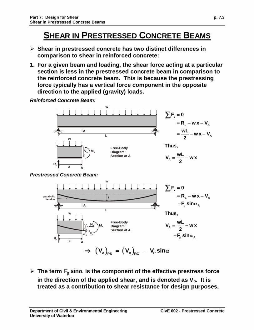
SHEAR IN PRESTRESSED CONCRETE BEAMS
Shear in prestressed concrete has two distinct differences in comparison to shear in reinforced concrete:
1. For a given beam and loading, the shear force acting at a particular section is less in the prestressed concrete beam in comparison to the reinforced concrete beam. This is because the prestressing force typically has a vertical force component in the opposite direction to the applied (gravity) loads.
Reinforced Concrete Beam:
y
L A
A
F 0
R w x V
wLw x V
2
Thus,
A
wLV w x
2
Prestressed Concrete Beam:
y
L A
p A
F 0
R w x V
F sin
Thus,
A
p A
wLV w x
2
F sin
A A PPS RCV V V sin
The term pF sin is the component of the effective prestress force
in the direction of the applied shear, and is denoted as Vp. It is treated as a contribution to shear resistance for design purposes.
A
Free-BodyDiagram:Section at A
Ax
L
RL
VA MA
w
w
A
parabolictendon
Free-BodyDiagram:Section at A
Ax
L
f
RL
VA
FpA
MANA
w
w
p. 7.4 Part 7: Design for Shear Shear in Prestressed Concrete Beams
Department of Civil & Environmental Engineering CivE 602 - Prestressed Concrete University of Waterloo
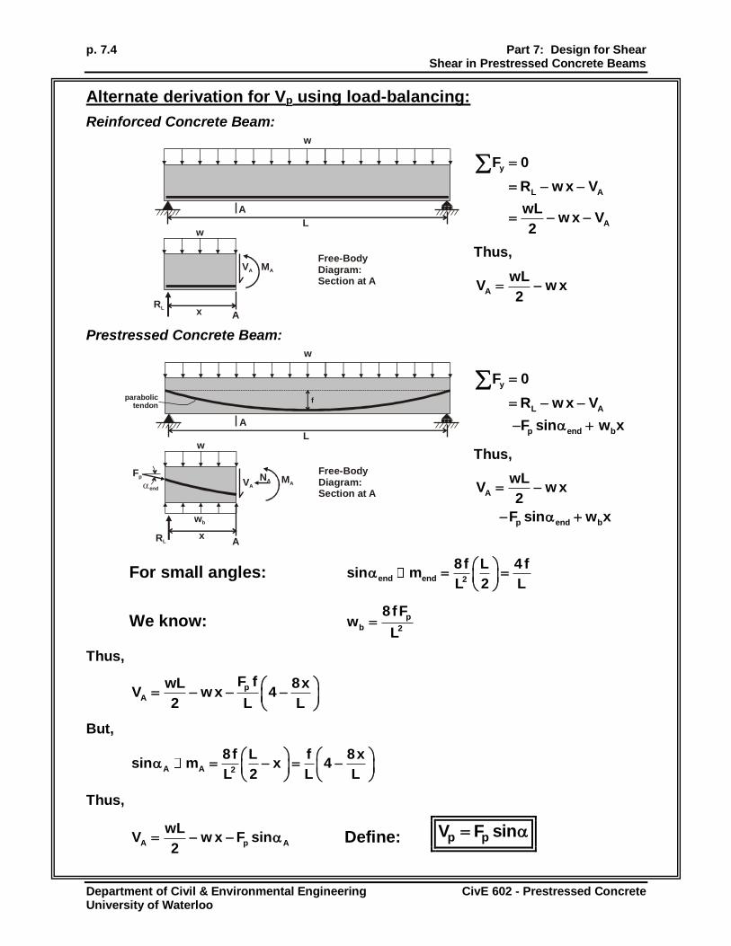
Alternate derivation for Vp using load-balancing:
Reinforced Concrete Beam:
y
L A
A
F 0
R w x V
wLw x V
2
Thus,
A
wLV w x
2
Prestressed Concrete Beam:
y
L A
p end b
F 0
R w x V
F sin w x
Thus,
A
p end b
wLV w x
2
F sin w x
For small angles: end end 2
8f L 4 fsin m
L 2 L
We know: p
b 2
8fFw
L
Thus,
p
A
F fwL 8xV w x 4
2 L L
But,
A A 2
8f L f 8xsin m x 4
L 2 L L
Thus,
A p A
wLV w x F sin
2 Define: p pV F sin
A
Free-BodyDiagram:Section at A
Ax
L
RL
VA MA
w
w
A
parabolictendon
Free-BodyDiagram:Section at A
Ax
L
f
RL
wb
VA
Fp
end
MANA
w
w

Part 7: Design for Shear p. 7.5 Shear in Prestressed Concrete Beams
Department of Civil & Environmental Engineering CivE 602 - Prestressed Concrete University of Waterloo
2. The prestress force introduces a compressive force on the concrete section. This compression reduces the diagonal (principal) tension developed within the web of the section, increasing the shear capacity of the concrete.
In addition, the angle of inclination of the principal tension with respect to the beam axis is reduced. As such, the inclined cracking that develops will be “flatter,” and stirrup spacing can be increased while still ensuring that at least one stirrup crosses the crack.
The positive effect of the compression force is accounted for in design by increasing the shear resistance provided by the concrete.
N.A.
N.A.
V -Vf p
V -Vf p
Mf
Fp
FpMf
C
A
B
C
A
B
(,) B C A
B
B

p. 7.6 Part 7: Design for Shear Design for Shear
Department of Civil & Environmental Engineering CivE 602 - Prestressed Concrete University of Waterloo
DESIGN FOR SHEAR
Many different approaches have been proposed for design of reinforced and prestress concrete elements for shear:
truss model
softened truss model
modified compression field theory
strut and tie model
See references for more information:
Collins and Mitchell text1
Naaman text2
MacGregor and Bartlett text3
CSA A23.3 DESIGN FOR SHEAR
Shear design is considered at the Ultimate Limit State
CSA A23.3-04 uses a sectional design method derived from the modified compression field theory for design of flexural elements for shear.
11.3 Design for Shear in Flexural Regions
General Method
“Simplified” Method is included for common conditions
Application of the simplified case is similar in style to the previous versions of A23.3 and to the ACI 318 Code.
The AASHTO LRFD provisions for shear design are similar to the CSA A23.3-04 provisions.
Shear design in “disturbed regions” or for deep beams is addressed using the Strut and Tie method (Clause 11.4).

Part 7: Design for Shear p. 7.7 CSA A23.3 Design for Shear
Department of Civil & Environmental Engineering CivE 602 - Prestressed Concrete University of Waterloo
CSA A23.3 SHEAR REQUIREMENTS (CHP. 11)
Vr Vf
Additional provisions for:
Minimum Shear Reinforcement (location and amount)
Maximum Spacing of Shear Reinforcement
Maximum Shear Resistance
Critical cross-section for shear design near supports
FACTORED SHEAR RESISTANCE
CSA A23.3-04 Clause 11.3.3
r c s pV V V V
r,max c c w v pV 0.25 f b d V
Where,
c = 0.65
dv = effective shear depth
= 0.9d or 0.72h, whichever is greater
bw = web width

p. 7.8 Part 7: Design for Shear CSA A23.3 Design for Shear
Department of Civil & Environmental Engineering CivE 602 - Prestressed Concrete University of Waterloo
CONCRETE RESISTANCE IN SHEAR, VC
CSA A23.3-04 Clause 11.3.4
Three contributions:
vcz shear in compression zone
va aggregate interlock
vd dowel action
va is the largest contribution to concrete shear strength
c c c w vV f b d
Where,
c = 0.65 (A23.3-04)
= factor to account for low-density concrete = 1 for normal density concrete
= factor accounting for shear resistance of cracked concrete, determined in Clause 11.3.6
Note that cf 8MPa when computing Vc.
For f’c > 64 MPa, use cf 8MPa
Accounts for reduced aggregate interlock in high strength concrete
T
C vcz
va
vd
V
V
V
Part 7: Design for Shear p. 7.9 CSA A23.3 Design for Shear
Department of Civil & Environmental Engineering CivE 602 - Prestressed Concrete University of Waterloo
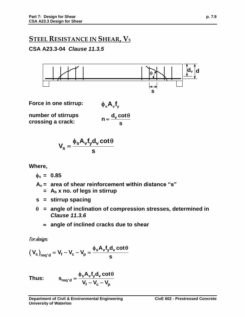
STEEL RESISTANCE IN SHEAR, VS
CSA A23.3-04 Clause 11.3.5
Force in one stirrup: s v yA f
number of stirrups crossing a crack:
vd cotn
s
s v y vs
A f d cotV
s
Where,
s = 0.85
Av = area of shear reinforcement within distance “s” = Ab x no. of legs in stirrup
s = stirrup spacing
= angle of inclination of compression stresses, determined in
Clause 11.3.6
angle of inclined cracks due to shear
For design:
s v y vs f c preq'd
A f d cotV V V V
s
Thus: s v y v
req'df c p
A f d cots
V V V
s
d dv
p. 7.10 Part 7: Design for Shear CSA A23.3 Design for Shear
Department of Civil & Environmental Engineering CivE 602 - Prestressed Concrete University of Waterloo
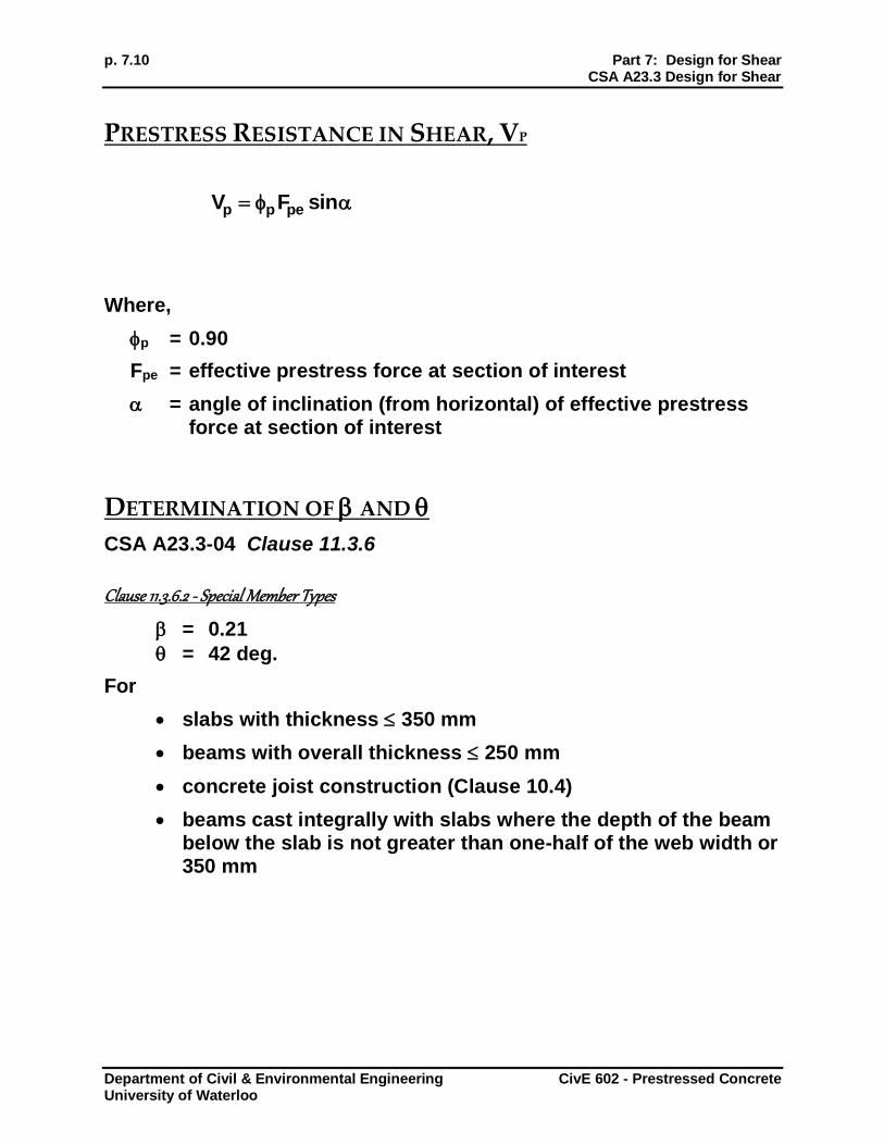
PRESTRESS RESISTANCE IN SHEAR, VP
p p peV F sin
Where,
p = 0.90
Fpe = effective prestress force at section of interest
= angle of inclination (from horizontal) of effective prestress force at section of interest
DETERMINATION OF AND
CSA A23.3-04 Clause 11.3.6
Clause 11.3.6.2 - Special Member Types
= 0.21
= 42 deg.
For
slabs with thickness 350 mm
beams with overall thickness 250 mm
concrete joist construction (Clause 10.4)
beams cast integrally with slabs where the depth of the beam below the slab is not greater than one-half of the web width or 350 mm

Part 7: Design for Shear p. 7.11 CSA A23.3 Design for Shear
Department of Civil & Environmental Engineering CivE 602 - Prestressed Concrete University of Waterloo
Clause 11.3.6.3 – Simplified Method
Applicable to cases other than Clause 11.3.6.2 and members not subject to significant axial tension
May be used for prestressed concrete elements
Limitations: f’c 60 MPa
fy 400 MPa
= 35 deg.
= 0.18 for sections containing at least the minimum transverse reinforcement (Clause 11.2.8.2)
= v
230
1000 d for sections containing no transverse
reinforcement and having maximum C.A.
size 20 mm
= ze
230
1000 s for sections containing no transverse
reinforcement and all aggregate sizes
sze = equivalent crack spacing parameter
= zz
g
35s0.85s
15 a
ag = maximum C.A. size
(CSA A23.3-04)
p. 7.12 Part 7: Design for Shear CSA A23.3 Design for Shear
Department of Civil & Environmental Engineering CivE 602 - Prestressed Concrete University of Waterloo
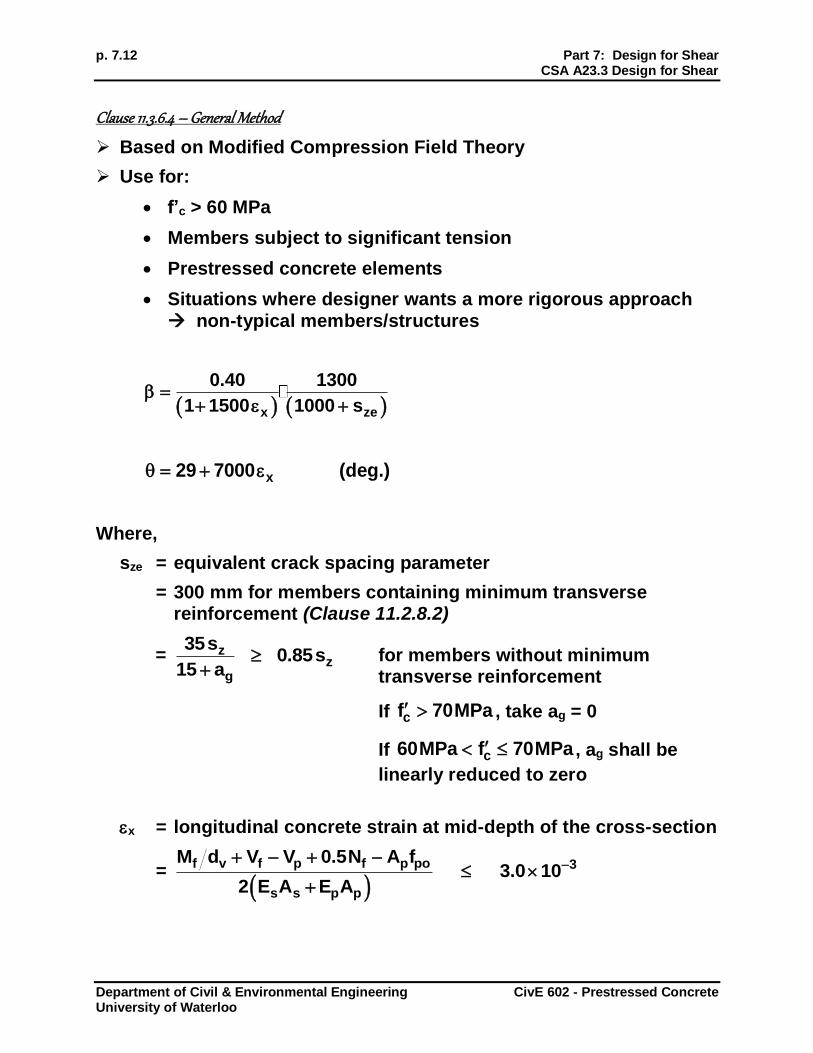
Clause 11.3.6.4 – General Method
Based on Modified Compression Field Theory
Use for:
f’c > 60 MPa
Members subject to significant tension
Prestressed concrete elements
Situations where designer wants a more rigorous approach non-typical members/structures
x ze
0.40 1300
1 1500 1000 s
x29 7000 (deg.)
Where,
sze = equivalent crack spacing parameter
= 300 mm for members containing minimum transverse reinforcement (Clause 11.2.8.2)
= zz
g
35s0.85s
15 a
for members without minimum
transverse reinforcement
If cf 70MPa , take ag = 0
If c60MPa f 70MPa , ag shall be
linearly reduced to zero
x = longitudinal concrete strain at mid-depth of the cross-section
=
f v f p f p po 3
s s p p
M d V V 0.5N A f3.0 10
2 E A E A
Part 7: Design for Shear p. 7.13 CSA A23.3 Design for Shear
Department of Civil & Environmental Engineering CivE 602 - Prestressed Concrete University of Waterloo
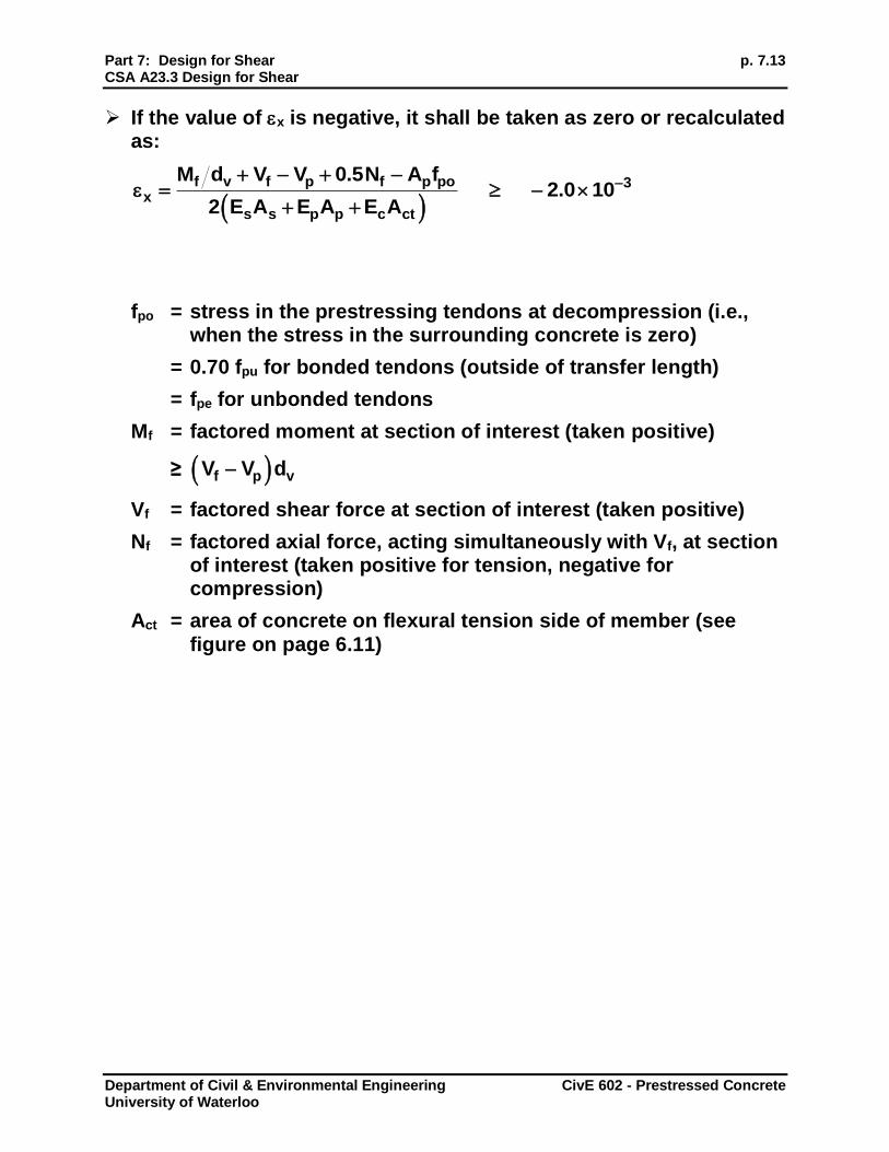
If the value of x is negative, it shall be taken as zero or recalculated as:
f v f p f p po 3
x
s s p p c ct
M d V V 0.5N A f2.0 10
2 E A E A E A
fpo = stress in the prestressing tendons at decompression (i.e., when the stress in the surrounding concrete is zero)
= 0.70 fpu for bonded tendons (outside of transfer length)
= fpe for unbonded tendons
Mf = factored moment at section of interest (taken positive)
≥ f p vV V d
Vf = factored shear force at section of interest (taken positive)
Nf = factored axial force, acting simultaneously with Vf, at section of interest (taken positive for tension, negative for compression)
Act = area of concrete on flexural tension side of member (see figure on page 6.11)
p. 7.14 Part 7: Design for Shear CSA A23.3 Design for Shear
Department of Civil & Environmental Engineering CivE 602 - Prestressed Concrete University of Waterloo
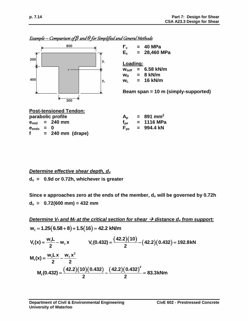
Example – Comparison of and for Simplified and General Methods
f’c = 40 MPa Ec = 28,460 MPa Loading: wself = 6.58 kN/m wD = 8 kN/m wL = 16 kN/m Beam span = 10 m (simply-supported)
Post-tensioned Tendon: parabolic profile emid = 240 mm eends = 0 f = 240 mm (drape)
Ap = 891 mm2 fpe = 1116 MPa Fpe = 994.4 kN
Determine effective shear depth, dv
dv = 0.9d or 0.72h, whichever is greater
Since e approaches zero at the ends of the member, dv will be governed by 0.72h
dv = 0.72(600 mm) = 432 mm
Determine Vf and Mf at the critical section for shear distance dv from support:
fw 1.25 6.58 8 1.5 16 42.2 kN/m
ff f
w LV (x) w x
2
f
42.2 10V (0.432) 42.2 0.432 192.8kN
2
2
f ff
w Lx w xM (x)
2 2
2
f
42.2 10 0.432 42.2 0.432M (0.432) 83.3kNm
2 2
yt
yb
800
300
400
200

Part 7: Design for Shear p. 7.15 CSA A23.3 Design for Shear
Department of Civil & Environmental Engineering CivE 602 - Prestressed Concrete University of Waterloo
Determine Vp:
for parabolic profile, tendon slope, 8 f
m xL
slope at critical section: 8 .240 10
m 0.432 0.432 0.0877110 2
p p peV F slope 0.90 994.4 0.08771 78.5kN
Calculate x:
f v f p p po
x
p p
6 3 3
M d V V A f
2 E A
83.3 10 432 192.8 10 78.5 10 891 0.7 1860
2 200,000 891
0.00239
Since x is negative, recalculate:
f v f p p po
x
p p c ct
6 3 3
M d V V A f
2 E A E A
83.3 10 432 192.8 10 78.5 10 891 0.7 1860
2 200,000 891 28,460 300 300
0.00015
Determine and for General Method:
Assume minimum transverse reinforcement is provided sze = 300 mm
x ze
0.40 1300
1 1500 1000 s
0.40 13000.516
1000 3001 1500 0.00015
x29 7000
29 7000 0.00015
28 deg.
p. 7.16 Part 7: Design for Shear CSA A23.3 Design for Shear
Department of Civil & Environmental Engineering CivE 602 - Prestressed Concrete University of Waterloo
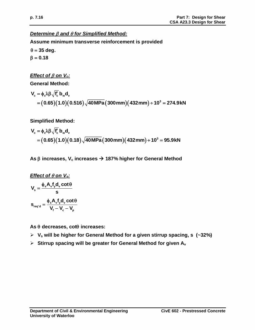
Determine and for Simplified Method:
Assume minimum transverse reinforcement is provided
35 deg.
0.18
Effect of on Vc:
General Method:
c c c w v
3
V f b d
0.65 1.0 0.516 40MPa 300mm 432mm 10 274.9kN
Simplified Method:
c c c w v
3
V f b d
0.65 1.0 0.18 40MPa 300mm 432mm 10 95.9kN
As increases, Vc increases 187% higher for General Method
Effect of on Vs:
s v y v
s
A f d cotV
s
s v y v
req'd
f c p
A f d cots
V V V
As decreases, cot increases:
Vs will be higher for General Method for a given stirrup spacing, s (~32%)
Stirrup spacing will be greater for General Method for given Av
Part 7: Design for Shear p. 7.17 CSA A23.3 Design for Shear
Department of Civil & Environmental Engineering CivE 602 - Prestressed Concrete University of Waterloo
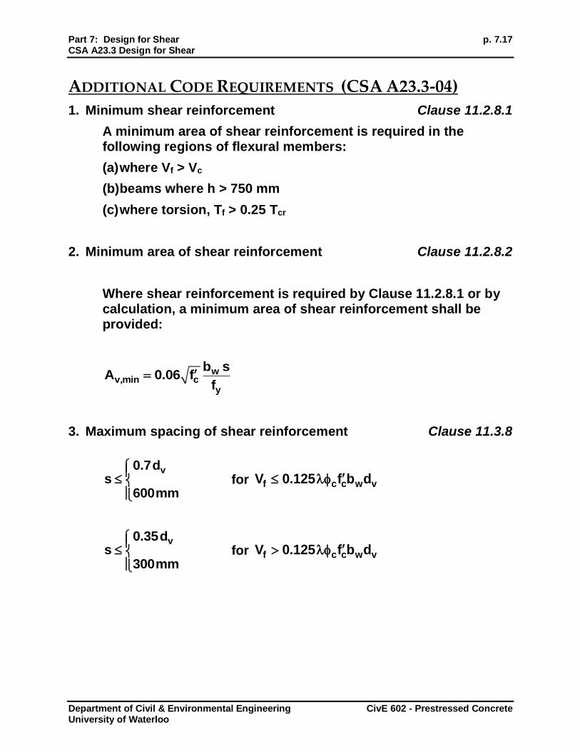
ADDITIONAL CODE REQUIREMENTS (CSA A23.3-04)
1. Minimum shear reinforcement Clause 11.2.8.1
A minimum area of shear reinforcement is required in the following regions of flexural members:
(a) where Vf > Vc
(b) beams where h > 750 mm
(c) where torsion, Tf > 0.25 Tcr
2. Minimum area of shear reinforcement Clause 11.2.8.2
Where shear reinforcement is required by Clause 11.2.8.1 or by calculation, a minimum area of shear reinforcement shall be provided:
wv,min c
y
b sA 0.06 f
f
3. Maximum spacing of shear reinforcement Clause 11.3.8
v0.7ds
600mm
for f c c w vV 0.125 f b d
v0.35ds
300mm
for f c c w vV 0.125 f b d
p. 7.18 Part 7: Design for Shear CSA A23.3 Design for Shear
Department of Civil & Environmental Engineering CivE 602 - Prestressed Concrete University of Waterloo
4. Maximum shear resistance Clause 11.3.3
r,max c c w v pV 0.25 f b d V
Thus,
s,max c c w v cV 0.25 f b d V
If too many stirrups are provided (Vs is too large), then the concrete web may crush before the stirrups yield.
If Vr,max < Vf, then the cross-section dimensions need to be increased.
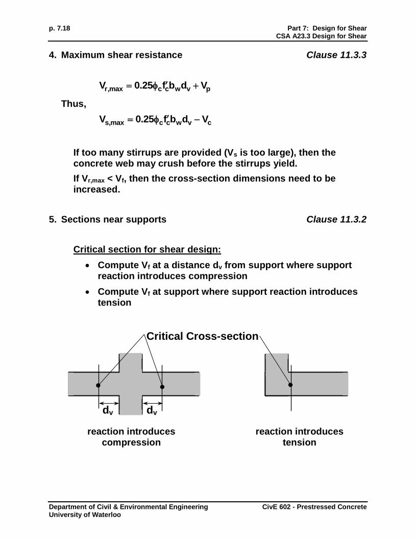
5. Sections near supports Clause 11.3.2
Critical section for shear design:
Compute Vf at a distance dv from support where support reaction introduces compression
Compute Vf at support where support reaction introduces tension
reaction introduces reaction introduces compression tension
dv dv
Critical Cross-section
Part 7: Design for Shear p. 7.19 CSA A23.3 Design for Shear
Department of Civil & Environmental Engineering CivE 602 - Prestressed Concrete University of Waterloo
SHEAR DESIGN PROCEDURE
Must satisfy Vr > Vf along length of member.
1. Determine if size of cross-section is adequate:
Check Vf Vr,max If not, increase bw and/or d
2. Determine and
3. Compute Vc (with and without stirrups)
4. Design stirrups for critical section, Vf, near support:
(a) If Vf Vc, then no stirrups are required
(b) If Vf > Vc, then:
Choose Av
Compute required spacing, s
Choose a reasonable value for s round to nearest multiple of 10 mm or 25 mm less than or equal to calculated s
Check Av > Av,min
Check s smax
5. Design stirrups for selected other sections along length of beam following Step 4. procedures
6. Determine stirrup layout along beam length. Draw Vr diagram for beam and compare to Vf envelope

p. 7.20 Part 7: Design for Shear References
Department of Civil & Environmental Engineering CivE 602 - Prestressed Concrete University of Waterloo
SHEAR DESIGN EXAMPLES FOR PRESTRESSED CONCRETE
See CAC Handbook Chapter 10, Examples 10.7 and 10.8
See CPCI Handbook Chapter 3, Examples 3-20 and 3-21.
REFERENCES
1). Collins, M.P., and Mitchell, D., (1991). “Prestressed Concrete Structures,” Prentice Hall, Englewood Cliffs, NJ.
2). Naaman, A. E., (2004). “Prestressed Concrete Analysis and Design,” 2nd Ed., Techno Press 3000, Ann Arbor, MI.
3). MacGregor, J.G., and Bartlett, F.M., (2002). “Reinforced Concrete Mechanics and Design,” 1st Canadian Ed., Prentice-Hall Canada, Scarborough, ON.