Embed Size (px)
Citation preview

Part 5Part 5
UTRAN Nokia PlatformsUTRAN Nokia Platforms

Nokia hardware platform
IPA2800 Nokia IP
DX200
HP/SUN
RNC

Radio Access NetworkMSC
NMS
TCSM
RANRAN Mobility Core
BSC MSC
MGW
2GSGSN
3GSGSN
RNC
RNC
A
Iu-PS
Gb
Iu-CS
Abis
Iub
Iur
GSM BTS
Triple
Mode
BTS
WCDMA BTS
IPBBWCDMA BTS

UTRAN architecture
Mobility CoreUTRANUTRAN
MSC
MGW
3GSGSN
RNC
RNC
Iu-CS
Iu-PS
Iur
Iu-CS
Iub
Iub
Iur
RNC
Iu-PS
WCDMA BTS
WCDMA BTS
WCDMA BTS
WCDMA BTS

Iur-Interface & Soft HandoverCN (Core Network)
circuit switched (cs) domain
packetswitched (ps) domain
3GMSC/VLR
3GSGSN
UTRAN
RNC
Node B
Node B
RNC
Node B
Node B (RNS)
Radio Network Subsystem (RNS)
Iub
Iub
Iur
Iu-PS
Iu-CS
Uu
UuUE
I can be connected to several
cells simultaneo
usly
Duplication of DL traffic, selection of UL
traffic
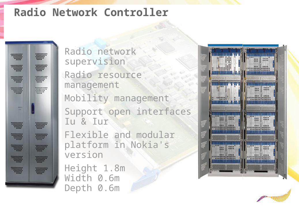
Radio Network Controller
Radio network supervisionRadio resource managementMobility managementSupport open interfaces Iu & IurFlexible and modular platform in Nokia's versionHeight 1.8mWidth 0.6m Depth 0.6m
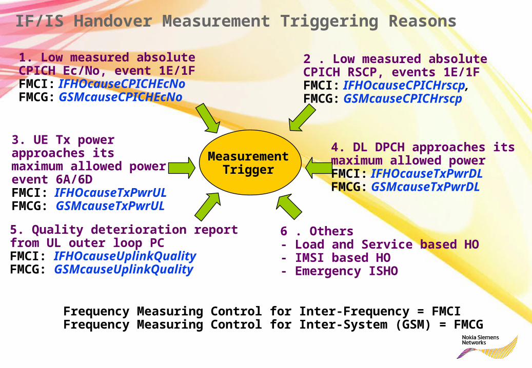
IF/IS Handover Measurement Triggering Reasons
4. DL DPCH approaches itsmaximum allowed powerFMCI: IFHOcauseTxPwrDLFMCG: GSMcauseTxPwrDL
5. Quality deterioration report from UL outer loop PCFMCI: IFHOcauseUplinkQualityFMCG: GSMcauseUplinkQuality
3. UE Tx power approaches itsmaximum allowed power, event 6A/6DFMCI: IFHOcauseTxPwrULFMCG: GSMcauseTxPwrUL
2 . Low measured absoluteCPICH RSCP, events 1E/1FFMCI: IFHOcauseCPICHrscp, FMCG: GSMcauseCPICHrscp
1. Low measured absolute CPICH Ec/No, event 1E/1F FMCI: IFHOcauseCPICHEcNoFMCG: GSMcauseCPICHEcNo
Measurement
Trigger
6 . Others- Load and Service based HO- IMSI based HO- Emergency ISHO
Frequency Measuring Control for Inter-Frequency = FMCIFrequency Measuring Control for Inter-System (GSM) = FMCG

Load based Handover GSM -> WCDMA
100%
80%
0%
Load reason Handoversfor speech
Load of GSM cell
Packet Data to WCDMAregardless of GSM load
Speech to WCDMAonly with high GSM load
Higher bit ratesfor data users
More capacity for
speech
Packet BCCH parameters can be usedto push GPRS mobiles to WCDMA

GSM
GSM
Load and Coverage Reason Handover
GSM
GSM highloaded
WCDMA lowloaded
GSM GSMWCDMA WCDMA
Load reason Handover for speech and for HSCSD
WCDMA GSM
Load reason Handover
Coverage reason Handover
WCDMA can be usedto relieve GSM overload
GSM can be used to extend WCDMA coverage area
Mobile moving

Radio Network Controller site solution
1 2
3
4
5
Scalable traffic capacity in 5 steps
• 48 - 196 Mbit/s nominal capacity• Any traffic mix of voice and data• Redundant structure
1800 mm
600 mm
600 + 600 mm

RNC Capacities

Base station sites:• Macrocell sites• Microcell sites• Picocell sites
Nokia WCDMA base station solution

Contents
Nokia WCDMA base station products
Nokia WCDMA base station architectures and configurations
Base station performance

What is the difference betweensite, cell and sector?
A site is a physical cabinet with carriers/TRXs.A site may have one or more cells.Cells that belong to a site with more than one cell are usually referred to as a sector.WCDMA
- 1 carrier= 5MHzGSM
- 1 TRX ~ 7 traffic channels
Different frequencies

RAS05.1ED (WBTS3.3)Configuration Type HW / RF modules1 8W COC,
FSC1 * Single
2+2+2 20W COC, FSi
1 * Dual + 1 * Single
2+2 20W COC, FSi
1 * Dual
2 20W COC, FSi
1 * Single
2+2+2 20W FSC 3 * Single2+2 20W FSC 2 * Single1+1+1+1 20/40W UOC,F
Si2 * Dual
1+1+1, 2+2+2 20/40W UOC, FSi
3 * Dual
1+1, 2+2 20/40W
UOC, FSi
2 * Dual
1-omni, 2-omni 20/40W UOC, FSi
1 * Dual
* = HW available in 2H/07 (after RAS05.1ED)
RAS05.1 (WBTS3.2)Configuration Type HW / RF modules1+1+1 20/40W
COC, FSi
1 * Single + 1 * Dual(2 * Dual possible too)
1+1+1 20/40W
FSC 3 x Single
1+1 20/40W COC, FSi
1 x Dual
1+1 20/40W
FSC 2 x Single
1 20/40W
COC, FSC
1 * Single
FrequenciesConfigurations
Available (est.)
4Q/2006
2Q/2007
3Q/2007
RAS05.1
RAS05.1 ED
RAS06
1Q/2008RAS06 ED
COC = Cost Optimized Configuration, 1 x Dual and 1 x Single RF Modules.FSC = Feederless Site Configuration, 1 x Single RF Module per sector.UOC = Upgrade Optimized Configuration, 1 x Dual RF Module per sector.FSi = Feederless Site Installation possible
3 * SingleFSC2+1+1 20W
RAS06 (WBTS4.0)
3 * DualUOC, FSi2+1+1 40W
1 * Dual + 1 * SingleCOC, FSi2+1+1 20WHW / RF modulesTypeConfiguration
3 * SingleFSC2+1+1 20W
RAS06 (WBTS4.0)
3 * DualUOC, FSi2+1+1 40W
1 * Dual + 1 * SingleCOC, FSi2+1+1 20WHW / RF modulesTypeConfiguration
3 * DualUOC, FSi3+3+3 20W
3 * DualUOC, FSi6x2 20W
RAS07, planned SW support for:
3 * DualUOC, FSi6x1 20/40W3 * DualUOC, FSi4+4+4 20W
HW / RF modulesTypeConfiguration3 * DualUOC, FSi3+3+3 20W
3 * DualUOC, FSi6x2 20W
RAS07, planned SW support for:
3 * DualUOC, FSi6x1 20/40W3 * DualUOC, FSi4+4+4 20W
HW / RF modulesTypeConfiguration
1900900850
1.7/2.12100
Band
IIFRFA/FRFB*VIIIFRDA/FRDB*VFRCA/FRCB*IVFRIA/FRIBIFRGC/FRGD
3GPP bandRF module Dual/Single
1900900850
1.7/2.12100
Band
IIFRFA/FRFB*VIIIFRDA/FRDB*VFRCA/FRCB*IVFRIA/FRIBIFRGC/FRGD
3GPP bandRF module Dual/Single
+ FREA 1700/1800

Base station performance in different frequency bands
The specification requirements for base station sensitivity and transmit power is same in all frequency bands
Operating Band
UL Frequencies UE transmit, Node B receive
DL frequencies UE receive, Node B transmit
I 1920 – 1980 MHz 2110 –2170 MHz II 1850 –1910 MHz 1930 –1990 MHz III 1710-1785 MHz 1805-1880 MHz IV 1710-1755 MHz 2110-2155 MHz V 824 – 849 MHz 869-894 MHz VI 830-840 MHz 875-885 MHz VII 2500-2570 MHz 2620-2690 MHz VIII 880 – 915 MHz 925 – 960 MHz IX 1749.9-1784.9 MHz 1844.9-1879.9 MHz
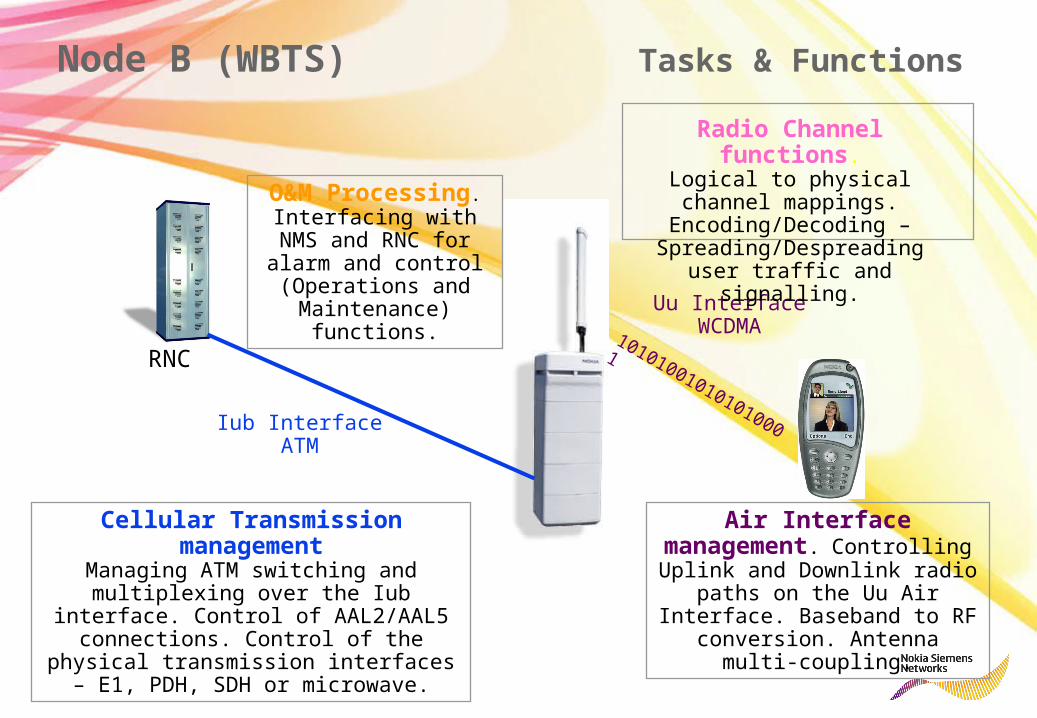
101010010101010001Iub InterfaceATM
Uu InterfaceWCDMA
Cellular Transmission managementManaging ATM switching and multiplexing
over the Iub interface. Control of AAL2/AAL5 connections. Control of the physical
transmission interfaces – E1, PDH, SDH or microwave.
Air Interface management. Controlling Uplink and Downlink
radio paths on the Uu Air Interface. Baseband to RF conversion. Antenna multi-
coupling.
O&M Processing.Interfacing with NMS
and RNC for alarm and control (Operations and Maintenance) functions.
Radio Channel functions.Logical to physical channel
mappings. Encoding/Decoding – Spreading/Despreading user
traffic and signalling.
RNC
Node B (WBTS) Tasks & Functions

Area type Dense Urban
Urban Suburb Rural
Speech 92 93 95 95 %144 kb/s NRT 85 85 85 85 %GSM1800 speech 85 85 85 85 %Cell range 1 1.6 2.3 5.2 km
Factors affecting cell size include:
Frequency band - 2000MHz much higher than GSM networks.
Traffic types - WCDMA user data rates drop off as the user moves further away from the Node B
User levels - Demand for mobile services will increase, leading to much greater user densities
Fast Data Users
Voice and Slow Data
Users
average projected coverage
WCDMA Cell Coverage

Voice traffic
Data Traffic
Soft Capacity
Cap
acity
per
cel
l per
car
rier
800kbps L1 rate
50 Erlang
More Voice Users Traffic Mix More Data Users
100% 50% 0% Load per carrier
Out
put P
ower
"Safe area"
Once Output Power Level on Uplink passes the Safe Area limit, the WCDMA air interface becomes flexible and after unstable. Load per carrier must be kept
below this limit
WCDMA Cell Capacity
Flexible areaunstable area

Nokia Flexi WCDMA Base StationWide Area high capacity WCDMA BTS;Modular structure enabling flexible expansions;Radio module;System module;Optional Power supply module;Optional Transmission Hub module;Modules can be used as building blocks for;Indoor sites;Outdoor sites;Macro, Mini sites;Feeder-less sites;Remote RF-Head/Distributed BTS;Small size Easier site acquisition;Nokia excellent Radio performance and high
12 carrier capacity
Height 133 mm
Width 448 mm for 19” rack installationDepth 410 mm without covers,
574 mm with front and back covers

Nokia Flexi WCDMA Base Station architecture
Open OBSAI (Open Base Station Architecture Initiative) interfacesDistributed Site SolutionCommon standard for different vendors
OBSAI Interface
OBSAI Interface
TRANSMISSIONTRANSMISSION ATM/IP/PDH/ATM/IP/PDH/SDHSDH
OBSAI Interface
PROCESSINGPROCESSING Base bandBase band
OBSAI InterfaceRADIORADIO WCDMA 2100 WCDMA 2100 MHzMHz
OBSAI Interface
CONTROLCONTROL
Additional FrequenciesAdditional FrequenciesNew radiosNew radios
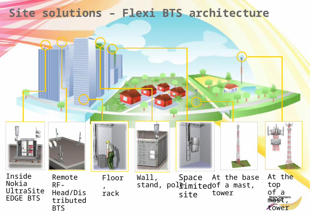
Inside Nokia UltraSite EDGE BTS
Wall, stand, pole
Floor, rack
At the base of a mast, tower
At the top of a mast, tower
Space limited site
Remote RF- Head/Distributed BTS
Site solutions – Flexi BTS architecture
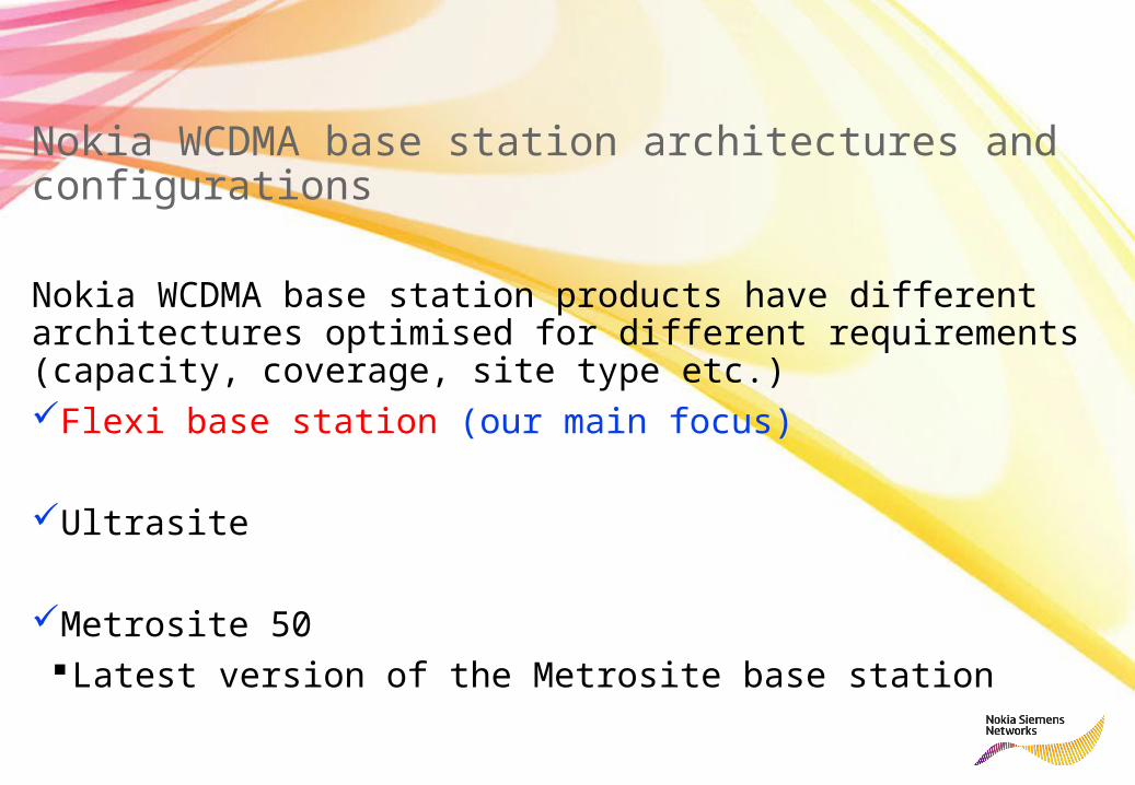
Nokia WCDMA base station architectures and configurations
Nokia WCDMA base station products have different architectures optimised for different requirements (capacity, coverage, site type etc.)Flexi base station (our main focus)
Ultrasite
Metrosite 50Latest version of the Metrosite base station

Configurations supported by each Node B type
Indoor and
Outdoor UltraSit
e Suprem
e
Indoor UltraSit
e Optima
Outdoor UltraSit
e Optima Compac
t (RF ext.)
Outdoor UltraSit
e Optima Compact (IBBU)
Indoor and
Outdoor UltraSite Triple Mode
MetroSite
MetroSite 50
Flexi
1+1+1+1+1+1 CEC Yes No Yes No No No No Yes1+1+1 CEC Yes Yes Yes Yes Yes No No Yes2+2+2 CEC Yes Yes Yes Yes Yes No No Yes1+1+1 ROC Yes Yes Yes Yes No No Yes NoOmni (single carrier) Yes Yes Yes Yes Yes Yes Yes YesOmni (dual carrier) Yes Yes Yes Yes No Yes Yes Yes

Nokia WCDMA base station products
Nokia WCDMA base station architectures and configurationsFlexi base station (our main focus)UltrasiteMetrosite
Nokia WCDMA base station performance

Nokia Flexi base station architecture
Nokia Flexi base station consists of three main modulesRF module Antenna filter Power amplifier Combiner DA/AD converter MHA power feed Remote tilting
System module Signal processing Transmission, Iub
Transmission module Optional Transmission hub

Optional Outdoor cabinet
BTS SystemModule
2 x 50 W RF Module 1…2 sector site
1+1 @ min. 40 W2+2 @ min 20 W
AC-> DC BBUAC (Optional)
Iub to RNCIub to BTS 2Iub to BTS n
Iub to BTS 1
OptionalTransmission Hub
50 W RF Module
3 sector site1+1+1 @ min 40 W2+2+2 @ min 20 W
Power consumption less
than 1 kW DC
Start up configuration:
1 system module+
2 RF modules(2+2+2) @ 20
W
Flexible BTS Siteevolution…

Optional Outdoor cabinet
BTS SystemModule
2 x 50 W RF Module
2 x 50 RF Module
… to Complete BTS SiteSolution
Iub to RNCIub to BTS 2Iub to BTS n
Iub to BTS 1
OptionalTransmission Hub
Optional2nd System Module
AC-> DC BBUAC (Optional)
•12 carriers•6 sectors
2 x 50 RF Module
3 sector site:2+2+2 @ min 40 W
or4+4+4 @ min 20 W
or6 sector site:6 x 2 @ min 20 W

BTS SystemModule
TwoPA RF Module
OnePA RF Module
Sector 1Sector 2
Sector 3
• with minimum 3-sector RF Module configuration
• Two PA RF Module• One PA RF Module
30 W PA
TX1
TX1 & RX1 Div RX1
1+1+1 @ 20 W
30 W PA
Sector 1
30 W PA
TX1
TX1
Sector 2
Sector 3 TX1 & RX1 Div RX1
TX1 & RX1 Div RX1
50 W PA
1+1+1 @ 40 W 40 W SW Licence
50 W PA
50 W PA
TX2
TX2
TX2
2+2+2 @ 20 W 2nd Carrier SW Licence
Capacity upgrade path to 2+2+2 (2/2)

Nokia Flexi WCDMA BTS Feederless Site
RF Module
RF Module
RF Module
BTS System Module Iub
Site installedoptical multimode cable up to 190 m
RF Modules located close to antennas
no 30…50 m long antenna feeders nor MHAs needed2.. 5 dB better uplink & downlink RF performanceOBSAI RP3-01 optical interface up to 190 m with

Capacity Upgrade with carrier addition
Dedicated HSPA carrier allows efficient utilisation of DL powerHSDPA traffic is not power controlled No power control headroom
CPICHCPICH
HS-DSCH
2 W
8 W
= Other common channels + R99= Other common channels + associated DCHs
CPICH
HS-DSCH
Only DCH traffic
12 W
2 W2 W
2 W
6 W
10 W total
16 W total
8 W
16 W total
Shared DCH + HSDPA
Dedicated HSDPA

Dynamic power allocation (RAS06)
BTS allocates all unused DL power up to the max cell powerAll the power available after DCH traffic, HSUPA control channels and common
channels can be used for HSDPA
PtxMax is the cell maximum output power defined by the management parameter PtxCellMax and the BTS capability (MaxDLPowerCapability )
PtxNC
PtxNRT
PtxHSDPA
PtxMax
PtxNonHSPA

Flexi WCDMA BTS BB Site Configurations with Rel 1 HW (FSMB)
1 System Module (FSMB):• Optimized for capacity upgrade• Support for max. 3 RF Modules• HW support for max 6 cell CCH• Max. HW capacity 240 CE• 32 CEs included in System Module Basic
OSW price→ max additional 208 CE on license
base (240-32=208)
2 System modules (2 * FSMB):• Available in RAS05.1ED (WBTS 3.3)• Support for max. 3 RF Modules• HW support for up to 12 cells CCH• Max. site HW capacity 480 CE• 2 * 32 CEs included in System Module Basic OSW
prices→ max additional 416 CE on license base
(480-64=416)• 471226A FSKA Flexi System Extension Kit (cable set) is required• The System Module that acts as a Baseband Extension needs to be
ordered without transport sub-module FTxx. In this case there is a dummy sub-module included to fulfil IP55 requirements.

WCDMA Flexi BTS Example Base Band Capacity for R99Rel1 HW
User data CE requiredBB Processing Capacity
1 System Module (FSMB, RAS05.1)
192 CE, 16 CE for CCH
BB Processing Capacity2 System Modules
(FSMB+FSMB, RAS06)2* 240 CE, 26 CE for CCH
16kbps/ voice 1 176 45432kbps 2 88 22764kbps 4 44 113128kbps 4 44 113256kbps (DL) 8 22 56384kbps 16 11 28
• 1+1+1,common channels included in calculations• Max.# CE licensed• Max. # of Simultaneous users on Flexi WCDMA BTS based on Baseband
capacity, excluding Air and Iub Interfaces

CE Utilisation (Calculated similary for both Nora and Flexi BTS)Same 1+1+1 configuration in use. Traffic mix over the measurement period is following16 CE for Common CH’s and 32 CE for HSDPA (=48CE’s)DL DCHSample 1: 100 AMR users+20*384 Kbits + CCH’s+HSDPA (16+32) = 100+(20*16)+48 =468 CE Sample 2: 80 AMR + 10*64 Kbits +10*384 Kbits + CCH’s + HSDPA (16+32) = 80 +
(10*4)+(10*16)+48 = 328 CESample 3: 120 AMR + 15*64 Kbits+20*384 Kbits+CCH’s+HSDPA (16+32) = 120+(15*4)+(20*16)+48
=588 CEUL DCHSample 1: 100AMR + CCH’s + HSDPA = 148 CESample 2: 80 AMR +10*64 Kbits + CCH’s + HSDPA = 100 + 10*4 + 48 =188 CESample 3: 120 AMR +15*64 Kbits + CCH’s + HSDPA = 120 +15*4 + 48 =228 CE
M5001C3 MAX_USED_CE_DL = 588 CE M5001C4 MIN_USED_CE_DL = 328 CE M5001C5 AVE_USED_CE_DL = 462 CE M5001C6 MAX_USED_CE_UL = 228 CE M5001C7 MIN_USED_CE_UL = 148 CE M5001C8 AVE_USED_CE_UL = 188 CE
BTS CE Capacity Measurement – Example of CE Utilisation

Transmission
Sites are connected together in different ways to optimise costoptimise cost, whilst assuring the best best qualityquality and redundancyredundancy.
The links can be wire, optical or radio microwave links.
RNC
IU IUr
BSC
MSCA
AXU
Multiplexer eg MetroHub
3G BTS 2G BTSATM crossconnect unit