Embed Size (px)
Citation preview

PART 3
SELECTION OF BRIDGES FOR SEISMIC CAPACITY IMPROVEMENT
(PACKAGE B AND C)


11-1
CHAPTER 11 PROCEDURES FOR SELECTION OF BRIDGES FOR OUTLINE DESIGN
11.1 General
In order to determine the bridges which require retrofitting or replacement to mitigate the seismic disaster inside and outside Metro Manila, two steps of screening were employed which includes inspection of the bridge conditions, environmental and social conditions around the bridge, and undertaking traffic volume survey on the roads related to the bridges. The prioritization and selection of the bridges to be retrofitted or replaced was carried-out based on these steps of screening.
The detailed evaluation criteria of first screening and second screening are described in 11.4 Evaluation Criteria for the First Screening and 11.5 Evaluation Criteria for the Second Screening.
The first screening aims to prioritize bridges which should be widely categorized by not only physical factors due to condition of the bridge but also seismic performance factors to reduce seismic hazards and geotechnical factors. The purpose of the second screening is to select the target bridges for the outline design stage.
11.2 Flowchart for Selection
The selection of priority bridges for seismic strengthening shall be undertaken as a two-screening process as shown in Figure 11.2-1.

11-2
Figure 11.2-1 Procedure of Identification of Prioritized Bridges

11-3
11.3 Contents of Survey for the First and Second Screenings
The detailed scope of works and survey method for each survey work is shown in Table 11.3-1.
Table 11.3-1 Scope of Works and Survey Method for Survey Work (1/2)
Survey Purpose Location Contents Method/Quantity Deliverable
Traffic Count Survey
For consideration and plan of detour, the number of vehicles affected during the construction period for seismic strengthening (maintenance, repair and reinforcement) and forecasting future traffic volume
To consider the traffic volume for detour road/bridge during seismic retrofit/replacement
To forecast future traffic volume to determine necessary number of lanes
Inside Metro Manila: 5 bridges
Outside Metro Manila: 7 bridges
Traffic Count Survey on the Bridge
Inside Metro Manila 24 hours:12 locations (on the bridge, one each for the selected bridge and one each on the upstream and downstream of 5 bridge) Outside Metro Manila 16 hours and 24 hours:7 locations (on selected bridge*8 bridges)
Traffic Survey Report
Intersection Traffic Count Survey
Inside Metro Manila 24 hours:12 locations (at road intersections of the bridge, one for selected bridge and one each for upstream and downstream of 5 bridges) Outside Metro Manila 12 hours and 24 hours:3 locations (one intersection per selected bridge*8 bridges)
Topographic Survey
To measure the topographic condition around the bridge site for seismic retrofit/ replacement
Inside Metro Manila: 5 bridges
Outside Metro Manila: 7 bridges
Centerline profile :8.0km (Inside MM: 2.5km, Outside MM: 5.5km)
Topographic Survey :About 38.5ha (Inside MM: 19.0ha, Outside MM: 19.5ha)
Cross section (@50m) :8.9km (Inside MM: 3.6km, Outside MM: 5.3km)
Temporary bench mark (one of either bank) :24 places (Inside MM: 10, Outside MM: 14)
Centerline profile of river :3.0km (Inside MM: 1.0km, Outside MM: 2.0km)
Cross section of river :About 14.6km (Inside MM: 3.8km, Outside MM: 10.8km)
Utility survey (visual survey)
Profile (H=1/1,000,V=1/100) Cross section (1/100) Plan (1/1,000) Profile of river (H=1/1,000,V=1/100) Cross section of river (1/100)

11-4
Table 11.3-1 Scope of Works and Survey Method for Survey Work (2/2)
Survey Purpose Location Contents Method/Quantity Deliverable
Socio Environmental Investigation
Prediction of Natural and Social Environmental Impact of Selected Bridges including alternative measure.
Consideration of Environmental Management Plan and Monitoring Plan
Inside Metro Manila: 5 bridges
Outside Metro Manila: 7 bridges
Collection and analysis of data and information Scoping Prediction of Natural and Social Environmental Impact of Selected Bridges Consideration of Alternatives Consideration of Mitigation Method Consideration of Environmental Management Plan and Monitoring Plan Support for Stakeholders' Meeting Support for Preparing the Draft Resettlement Action Plan
Report Environmental Check List Draft Primary Resettlement Action Plan
Bridge Soundness Inspection
Assistance of Bridge Soundness Inspection/Test
Inside Metro Manila: 5 bridges
Outside Metro Manila: 7 bridges
Bridge Soundness Inspection/Test ・ Visual Inspection/ Shape and Dimension Measurement/ Crack Inspection/
Compressive Strength Test (Core sample, Schmidt hammer rebound test)/ Neutralization Test (Concrete chipping, Coring, Drilling)/ Reinforcing Bar Detection (Electromagnetic wave radar method)/ Shape and Dimension Measurement/ Scouring Measurement
・ Natural Vibration Test/ Impact Vibration Test
Bridge Inspection Report
Geotechnical Investigation
To determine the geological/ geotechnical condition and properties at the bridge sites required for seismic design
Inside Metro Manila: 5 bridges
Outside Metro Manila: 7 bridges
Boring 810m (Inside MM: 230m, Outside MM: 580m)
Standard Penetration Tests 810 m (Inside MM: 230m, Outside MM: 580m)
Laboratory Tests ・ Classifications/ Specific gravity/ Natural moisture contents/ Atterberg Limit/
Grain Size Downhole Shear Wave Test Analysis
Geotechnical/ Soil Survey Report
Design Earthquake Ground Motion
Assistance of determination of design earthquake load
Inside Metro Manila: 2 bridges
Outside Metro Manila: 5 bridges
Nationwide
Site-specific design spectra (L1, L2) for 7 bridge sites PGA contour map for Philippine rock sites corresponding to 475-year return period
(equivalent to 15% probability of exceedance in 75 years) Contour maps of spectral acceleration at PGA, 0.2 sec, and 1.0 sec for Philippine
site class B corresponding to 1000-year return period (equivalent to 7% probability of exceedance in 75 years).
Report

11-5
11.4 Evaluation Criteria for the First Screening
The evaluation criteria for the first screening to prioritize bridges should be widely categorized by not only Physical Factors due to the condition of the bridge but also Seismic Performance Factors to reduce seismic hazards and Geotechnical Factors which are weighted 50 points, 30 points and 20 points respectively. Each category has also 3 or 4 evaluation criteria as shown in Table 11.4.1-1 and Table 11.4.1-2.
Table 11.4.1-1 Evaluation Criteria of First Screening
No. Category Evaluation Criteria Maximum
Score
1.
Physical Factors (50 points)
Construction Year & AppliedSpecification
10
2. Vulnerability of Bridge 30 3. Road Importance 5 4. Load Carrying Capacity 5 5.
Seismic Performance Factors (30 point)
Seating Length 10
6. Fall-down Prevention Apparatus
10
7. Type of Bridge 10 8.
Geotechnical Factors (20 points) Liquefaction Potential 10
9. Soil Classification 5 10. Impact to Environment 5
Total Point 100
Table 11.4.1-2 Scoring System for Evaluation Criteria
Grade Rate Year (10) Score (30) Ratio (5) Ratio (5) Ratio (10)
Good 0% After 2000 0 Under 31 0 Over 20ton 0 None 0 A and B< N 0
Fair 30% 1993 - 1999 3 31-40 9 15-19ton 2 Less 2 - 3
Poor 60% 1964 - 1992 6 41-50 18 10-14ton 3 Important 3 A < N < B 6
Bad 100% Before 1963 10 Over 50 30 Under 10ton 5 Very 5 N < A and B 10
A: AASHTO criteriaB: JRA criteria
Grade Rate Percent (10) Type (10) Class (10) Class (5) Rehabilitation (5)
Good 0% 100% Function 0Continuous rigid frame
type bridge0 None 0 Type-I 0
None(No impact)
0
Fair 30% 80% Function 4 Continuous bridge 4 Low 3 Type-II 2Small
(1-impact)2
Poor 60% 50% Function 6Hinge/ rigid frame type
(Simply supported)6 Moderate 6 Type-III 3
Moderate(2-impact)
3
Bad 100% None 10 Simply supported 10 High 10 Type-IV 5Large
(More than 2-impact)
5
Impact to Environment
Conditions of BridgeConstruction Year &Applied Specification
Loading Capacity
Soil Classification
Description Seating LengthBridge Importance
Description Fall Prevent Devices Type of Bridge Liquefaction

11-6
11.4.1 Construction Year and Applied Specification
Seismic resistance performance of bridges is directly related to year of construction and specifications applied in the design. That is, old bridges are more prove to earthquake than new bridges. Construction year and applied specification fall into the following four (4) categories:
Construction Year & Applied Specification Year Description
After 2000 R-Factor Design, AASHTO LRFD Specification 2nd – 4th Edition 1993 - 1999 R-Factor Design, AASHTO LRFD Specification 1st Edition 1964 - 1992 Seismic Design Force, AASHTO 9th ~14th Edition Before 1963 No seismic consideration, AASHTO 1st ~8th Edition
11.4.2 Conditions of Bridge
Conditions of bridge members are verified by visual inspection based on the criteria of BMS using DPWH’s inspection sheet modified by the JICA Study Team as shown in Appendix 5. Defective members are rated by four (4) categories such as Good, Fair, Poor and Bad and weighted 0, 3, 6, 10 points for primary members and 0, 2, 3, 5 points for secondary members respectively with a total score of 540 points. The rating scores may be slightly different between Package B and C because bridges are inspected by different inspectors even if based on the same evaluation criteria. Table 15.1.2-1 and Table 15.2.1-1 highlight the results of bridge soundness evaluation. From the results of visual inspection for each bridge, the accumulated rating score is varied from 9 to 57 points for Package B Bridges and from 11 to 46 for Package C. Condition of Bridge is divided into the following four (4) groups:
Condition of Bridges Score Description
Under 31 Good Condition 31 - 40 Fair Condition 41 - 49 Poor Condition Over 50 Bad Condition
11.4.3 Load Capacity
Load capacity is verified from load posting signs at both ends of the bridge that regulates the maximum vehicle load.
11.4.4 Bridge Importance
Bridge is a part of the road so that the importance of the road is synonymous with Bridge Importance. All candidate Bridges in Package B and C were constructed along important roads but arterial roads and circumferential roads in Manila and roads for economics, security and defense purposes are considered to be very important as distinguished from other roads.

11-7
11.4.5 Seating Length
The seating length in AASHTO is calculated by Eq. A of N=305 +2.5L+10H (mm) considering elastic displacement of bridge members which is not enough for global displacement of bridge during seismic ground motion. On the other hand, the seating length in JRA is calculated by Eq. B of Se= 0.7 +0.005 L (m) considering not only elastic displacement of substructure but also displacement of foundation with plastic behavior in liquefaction and fault-related damage. The resulting seat length in JRA is basically greater than that of AASHTO. Bridges constructed on soft and sanity layers, especially in large cities and along arterial roads are, in most case, easily subjected to liquefaction or horizontal and vertical displacements during earthquake. However, AASHTO LRFD specification is basically considered on the rock and modified for soft layers. In such different geological conditions between USA and the Philippines, minimum requirement of seating length should be modified toward JRA specification. Therefore, seating length is divided into the following 3 categories;
Existing Seating Length (N) Ratio Description
N > A and B SL clears both minimum required seating length of AASHTO and JRA A < N < B SL clears AASHTO but unclear JRA minimum required seating length N < A and B SL doesn’t clear both minimum required seating length of AASHTO and JRA
Note: A: AASHTO B: JRA
11.4.6 Fall-down Prevention Devices
The criteria focus on the availability of fall-down prevention device and its degree of functionality. Fall-down prevention device on several bridges have been provided during the ADB Retrofitting project in the 1990’s, but some of them were totally gone or partially broken. Most of them are not functioning properly.
11.4.7 Type of Bridge
The type of bridges influences the seismic performance of bridges. Continuous rigid frame bridges have the highest performance and continuous girder bridges have higher seismic performance than simply supported bridges. Even if bridges are simply supported, rigid frame/hinge type bridges have higher seismic performance than simply supported girder bridges.
11.4.8 Liquefaction Potential
Liquefaction potential is verified by geological Engineer in JICA Study Team from boring data near the bridge location or from liquefaction hazard map of PHIVOLCS and divided into the following four (4) classes such as High, Moderate, Low and None.

11-8
11.4.9 Soil Classification
Soil classification is verified by geological Engineer in JICA Study Team from boring data near the bridge location or from geological map of PHIVOLCS and divided into the following four (4) types based on AASHTO specifications such as Type-I, Type-II, Type III and Type-IV. In global evaluation table, soil classifications in JRA specification are shown comparing with AASHTO specifications. Relation between both soil classifications is roughly shown in the following table:
Soil Classification Class AASHTO JRA
Rock, Stiff Soil Type-I Type-I
Stiff Clay Type-II Soft to medium stiff Clay and Sand
Type-III Type-II
Soft Clay or Silts Type-IV Type-III
11.4.10 Impact to Environment
Seismic improvement measures for bridges will impact the surrounding environment such as 1) Resettlement of affected persons, 2) Traffic disturbance, 3) Noise & pollution 4) Restricted area for political, economic and defense purpose against the proposed rehabilitation method during implementation stage. During the 1st Screening, impact to environment is determined by the number of impacts to surrounding areas identified by site inspections. Therefore, impact to environment is divided into the following 4 categories;
Impact to Environment Degree Number of Impact
None No impact Small 1-impact Moderate 2-impacts Large More than 2-impacts
11.5 Evaluation Criteria for the Second Screening
11.5.1 Purpose of the Second Screening
The purpose of the establishment of evaluation criteria for the second screening is to select target bridges for the outline design stage. The target bridges for outline design for each Package are originally intended as follows:
Package B: Three bridges will be selected basically with replacement options, including
partial replacement (however, if Ayala Bridge is excluded, the number of target bridges
becomes two).
Package C: Five bridges will be selected basically with retrofit options. Note: Although the number of target bridges and improvement measures have been initially decided
as part of the scope of this project (as intended above), the final target bridges for Package B and C and their corresponding improvement measures for outline design will be decided after through discussions and consultations with DPWH and JICA.

11-9
11.5.2 Process of Establishment of Selection Criteria
From the above intention in Section 14.3.1, whether the bridges should be retrofitted or replaced for improvement measures in terms of seismic vulnerability should be carefully studied and determined at relatively early stage. The following selection process for second screening, therefore, is taken as shown in Figure 11.5.2-1. Step 1: Identification of issues focusing on the following:
(1) Seismic Vulnerability
Earthquake Resisting System (simply supported or continuous, weight balance (eccentric
loads), stiffness balance between adjacent piers including difference in soil type and soft
ground depth)
Unseating/Fall-Down Prevention System (falling down prevention devices (both longitudinal
and transverse directions), bearing type and damage, seat length)
Substructures (capacity-demand ratio, deterioration or defects of columns and/or walls, height
of abutment (embankment), built year)
Foundations (foundation type is known or unknown, soil type, liquefaction potential)
(2) Structural Soundness (mainly superstructures)
Items for rehabilitation needs (the extent of damages)
Remaining life (built year and the extent of damages of superstructures) (3) Seismic Hazard
Distances from Active Faults Step 2: Comparison study on improvement measures focusing on the following:
Improvement measures for seismic vulnerability and structural deficiencies
Cost comparison for two options, retrofit and replacement
Construction difficulty and potential of PAPs Step 3 Establishment of priority evaluation criteria and recommendation on bridges for outline design

11-10
Step 1 Identification of Issues
Traffic Conditions near Target Bridges
Traffic Volume Count Survey
Road Network near Target Bridges
(Alternative Routes)
Bridge Seismic Vulnerability and Structural Soundness
Topographic Survey
Bridge Condition Inspection
Geotechnical Survey
Environmental Conditions near Target Bridges
Identification of Issues on Bridge Seismic Vulnerability, Entire Structural Soundness,
and Seismic Hazard
Identification of Land Useand Potential of Project
Affected Persons (PAPs)
Step 2 Comparison Study on Improvement Measures
Comparison Study on Improvement Measures
(Project Cost, Construction Difficulty, Potential of PAPs)
Recommendation of Improvement Measures
Summary of Traffic Issues
Establishment of Evaluation Criteria(Three Components: Seismic
Vulnerability, Structural Soundness, and Importance)
Recommendation on Bridges for Outline Design
Step 3 Priority Evaluation and Recommendation for Outline Design
Section Section Section
Section Section Section
Section Section
Section
Section
Section Section
Section
Section
Section
Figure 11.5.2-1 Process for Establishment of Priority Evaluation Criteria and Selection of Bridges for Outline Design

11-11
11.5.3 Priority Evaluation Criteria
(1) Components for Evaluation and Rating Weight
Evaluation components and rating weight are shown in Table 11.5.3-1.
Table 11.5.3-1 Components for Evaluation and Rating Weight
Evaluation Components
Bridge Condition
Importance Total Seismic Vulnerability
Structural Soundness
Rating Weight 60 % (points) 20 % (points) 20 % (points) 100 % (points)
(2) Evaluation Items and Weight for Seismic Vulnerability
Table 11.5.3-2 Components of Seismic Vulnerability and Rating Weight
Component Evaluation Item Weight for Rating
Earthquake Resisting System
1. Difference in soil types between adjacent piers 22. Continuous or simply supported bridge 33. Eccentric loads (longitudinal and transverse directions) 54. Pier Type (single column/wall or multiple columns) 35. Height of Abutment (Embankment) 26. Built Year 5
Sub-total (1) 20 pointsUnseating Fall-down Prevention System
7. Unseating/Fall-down prevention devices (both longitudinal and transverse directions)
5
8. Bearing 59. Seat length 5
Sub-total (2) 15 points
Foundation
10. Foundation type (known or unknown) 311. Scouring 312. Soil type 313 Liquefaction potential 6
Sub-total (3) 15 pointsSeismic Hazard 14. Distance from active faults 10
Sub-total (4) 10 pointsTotal 60 points
Earthquake Resisting System (20 Points) 1. Difference in soil types between adjacent piers (2 points) (1) Same 0 (2) Soil Type I (or II) and II (or III) 1 (3) Soil Type I and III 2
2. Continuous or simply supported bridge (3 points) (1) Continuous 0 (2) Simply supported 3

11-12
3. Eccentric loads (longitudinal and transverse directions) (5 points)(1) Balance Ratio: 1.0 0 (2) Balance Ratio: 1.0 - 1.5 3 (3) Balance Ratio: over 1.5 5
Notes: Balance ratio can be judged from the difference in mass eccentricity (i.e. eccentric columns and span length ratio (similar to Lambingan Bridge with adjacent span length ratio of 0.3:1.0 or balance ratio of 3.33))
4. Pier Type (single column/wall or multiple columns) (3 points) (1) Multiple columns 0 (2) Single column/wall 3
Notes: Non-rigid frame structures are not recognized as “Multiple Columns” even though they consist of more than one column. 5. Height of Abutment (Embankment) (2 points)
(1) 0 - 5.0 m 0 (2) 5.0 - 10.0 m 1 (3) Over 10.0 m 2
6. Built year (DPWH D.O.75 “Seismic Design” was issued in 1992) (5 points)
(1) After year 1992 0 (2) 1992 and earlier 5
Unseating/Fall-Down Prevention System (15 points) 7. Unseating/Fall-down prevention devices (longitudinal and transverse directions) (5 points)
(1) Good (Seismic restrainers are installed for both directions & functionable.) 0 (2) Fair (Seismic restrainers are installed for one direction & functionable.) 1 (3) Poor (Seismic restrainers are installed, but not functionable enough.) 3 (4) None (No seismic restrainers are installed.) 5
8. Bearing (5 points)
(1) Minimal (Seismically resistible type & in good condition) 0 (2) Moderate (Seismically resistible type, but in inappropriate condition) 3 (3) Serious (Seismically vulnerable type or/and severely damaged/corroded) 5
9. Seat length (5 points)
(1) Enough (The seat lengths satisfy JRA criteria.) 0 (2) Short (The seat lengths satisfy AASHTO criteria.) 3 (3) Very Short (Some of seat lengths don’t satisfy AASHTO criteria.) 5
Foundation (15 points) 10 Foundation type (known or unknown) (3 points)
(1) Known (identified type and seismic capacity sufficient) 0 (2) Unknown (unidentified) 3
11. Scouring (3 points)
(1) None 0 (2) Unknown (Ex. conditions of piers in water) 2 (3) With evidence or potential for scouring 3

11-13
12 Soil type (3 points)(1) Soil type I (Firm) 0 (2) Soil type II (Moderate) 2 (3) Soil type III (Soft) 3
13 Liquefaction potential (6 points)
(1) Firm, clayey soil or over than 30 of N value 0 (2) Low potential (Sand or silty sand (20 - 30)) 2 (3) High potential (Sand or silty sand (10 - 20)) 4 (4) Very high potential (Sand or silty sand (less than 10 of N value)) 6
Notes: Target soil for assessment of liquefaction potential is sand or silty sand distributing under water and shallower than 20 m in depth.
Seismic Hazard (10 points) 14 Distance from active faults (based on Uniform Building Code (UBC)) (10 points)
(1) Small (Over than 10.0 km) 0 (2) Moderate (5.0 km - less than or equal 10.0 km) 3 (3) Serious (2.0 km - less than or equal 5.0 km) 6 (4) Fatal (Less than or equal 2.0 km) 10
(3) Evaluation Items and Weight for Structural Soundness (Superstructure)
Table 11.5.3-3 Evaluation Items and Rating Weight
Component Evaluation Item Weight for Rating
Superstructures 1. Primary members 102. Secondary members 23. Deck slab 3
Sub-total (1) 15Substructures 4. Deterioration of columns/walls 5
Sub-total (2) 5Total 20 points
Superstructure (15 points) 1. Primary members (10 points)
(1) Good or Small (No need for repair) 0 (2) Moderate (Repair work is necessary.) 3 (3) Serious (Additional reinforcement is recommended.) 5
2. Secondary members (2 points)
(1) Good or Small (No need for repair) 0 (2) Moderate (Repair work is necessary.) 1 (3) Serious (Additional reinforcement is recommended.) 2
3. Deck slab (3 points)
(1) Good or Small (No need for repair) 0 (2) Moderate (Repair work is necessary.) 1 (3) Serious (Replacement is recommended.) 3

11-14
Substructure (5 points) 4. Deterioration of columns/walls (5 points)
(1) Good or Small: No need for repair 0 (2) Moderate: Moderate damages such as cracks/hanycomb are inspected. (The structural soundness can be improved by repair works.)
3
(3) Serious: Severe damages such as cracks/hanycomb are inspected. (Damages are too severe to improve the structural soundness by repair works.)
5
(4) Importance
Since every target bridges are located on essential roads, road classes where bridges are located are not included in the criteria, focusing only on traffic volume passing through the bridges and existence of alternative bridges. Traffic volume of Package C may be largely so different from that of Package B that it is better for evaluation criteria to be prepared for Package B and C separately.
Table 11.5.3-4 Components of Evaluation Criteria for Importance and Rating Weight Component Evaluation Item Weight for Rating
1 Traffic volume Traffic volume (pcu) (AADT) 52 Alternative bridge(s) Existence of alternative bridge(s) 15
Total 20 points 1.1 Traffic volume (Package B) (5 points) (AADT)
(1) Less than 50,000 pcu 0 (2) 50,000 - 100,0000 pcu 3 (3) Over than 100,000 pcu 5
1.2 Traffic volume (Package C) (5 points) (AADT)
(1) Less than 2,000 0 (2) 2,000 - 5,000 3 (3) Over than 5,000 5
2. Alternative bridge(s) (15 points)
(1) Less than 1 km 0 (2) 1 km - 3 km 5 (3) 3 km - 10 km 10 (4) More than 10 km or no alternate bridge 15

12-1
CHAPTER 12 THE FIRST SCREENING
12.1 The First Screening for Package B
12.1.1 Results of the First Screening
(1) Results of the Bridge Soundness Survey
Bridge soundness surveys were conducted by visual inspection and the results of the inspection summarized in the following tables;

12-2
1) Delpan Bridge
H. STRUCTURAL CONDITIONS OF BRIDGE COMPONENTS
Good Fair Poor Bad
0% 30% 60% 100%
(50) Deck Slab Concrete Cracking 10 ○ 3 (Primary) Exposure/Corrosion of Rebars 10
Scaling/Spalling 10 ○Delamination 10Hanycomb 10Waterleaking 10 ○ 3
(51) Concrete Beam/ Cracking 10 ○ 6 Girder Exposure/Corrosion of Rebars 10 ○
(Primary) Spalling, Scaling,Disintegration 10 ○
Delamination 10Hanycomb 10Waterleaking 10 ○ 6
(52) Steel Beam/ Corrosion 10 Truss Members Cracking 10 (Bracings, etc.) Deformation/Buckling 10 (Primary) Abnormal Vibrations 10
Loose Connection 10Paint Peel off 10
(53) Shoe/Bearing Steel Waterleaking 10 ○ 6Abnormal Space/Noise 10Difference in elevation 10Displacement 10 ○
(Primary) Rubber Cracking/Rupture 10(54) Abutments Concrete Settlement 10 (Primary) Masonry Movement 10
Others Delamination 10Scouring 10Spalling, Scaling,Disintegration 10Cracking concrete 10 ○Exposure/Corrosion of Reinf. 10 ○
Honeycomb 10(55) Piers Concrete Settlement 10 (Primary) Masonry Movement 10
Others Delamination 10Scouring 10Spalling, Scaling,Disintegration 10Cracking concrete 10 ○ 3Exposure/Corrosion of Reinf. 10 ○
Honeycomb 10(56) Curb and Railing Concrete Cracking 5 ○ 3 (Secondary) Exposure/Corrosion of Reinf. 5
Spalling 5 ○ 3Impact Damaged 5 ○ 3
Reinforced
Concrete
Severity of Damage
0
RatingScore
Accumrated
Rating of
damage
6
Rating of
damage
12
Component MaterialType of Damages/
6Prestressed
Concrete
Bridge MemberRemarks
0
3
9
Good Fair Poor Bad
0% 30% 60% 100%
(57) Expansion Joint Steel Waterleaking 10 (Primary) Others Abnormal Space/Noise 10
Difference in elevation 10Displacement 10 ○ 6Cracking/Rupture 10 ○
(58) Painting Cond. Discoloration 10 (Primary) Rust 10
Exfoliation 10(59) Drainage Pipe PVC Clogged 5 (Secondary) Steel Cracks 5
Others (60) Slope Protection Gabions Settlement 5 (Secondary) Others Erossion 5
Scouring 5Cracks 5Others
(61) Approach Road Concrete Cracking 5 ○ 3 (Secondary) Asphalt Pot-holes 5 ○ 3
Others (62) River Condition Scouring 5 (Secondary) Sedimentation 5
Others
(63) Total Condition Rating 540 48
0
6
0
ComponentRatingScore
0
0
Rating of
damage
Accumrated
Rating of
damageMaterial
Type of Damages/Severity of DamageBridge Member
Expansion of I-
girder
6
Remarks

12-3
2) Jones Bridge
H. STRUCTURAL CONDITIONS OF BRIDGE COMPONENTS
Good Fair Poor Bad
0% 20% 50% 100%
(50) Deck Slab Concrete Cracking 10 ○
(Primary) Exposure/Corrosion of Rebars 10Scaling/Spalling 10Delamination 10Honeycomb 10Waterleaking 10 ○
(51) Concrete Beam/ Cracking 10 Girder Exposure/Corrosion of Rebars 10 (Primary) Spalling, Scaling,Disintegration 10
Delamination 10Honeycomb 10Waterleaking 10
(52) Steel Beam/ Corrosion 10 ○
Truss Members Cracking 10 (Bracings, etc.) Deformation/Buckling 10 (Primary) Abnormal Vibrations 10
Loose Connection 10Paint Peel off 10 ○
(53) Shoe/Bearing Steel Corrosion 10 ○
Loose ConnectionAbnormal DisplacementBulging/Rupture
(Primary) Rubber Bed (Support ) Damage 10(54) Abutments Concrete Settlement 10 (Primary) Masonry Movement 10
Others Delamination 10Scouring 10Spalling, Scaling,Disintegration 10Cracking concrete 10 ○Exposure/Corrosion of Reinf. 10Honeycomb 10
(55) Piers Concrete Settlement 10 (Primary) Masonry Movement 10
Others Delamination 10Scouring 10Spalling, Scaling,Disintegration 10Cracking concrete 10 ○Exposure/Corrosion of Reinf. 10Honeycomb 10
(56) Curb and Railing Concrete Cracking 5 ○
(Secondary) Exposure/Corrosion of Reinf. 5Spalling 5Impact Damaged 5
0
Type of Damages/RatingScore
0
Accumrated
Rating of
damageRemarks
Component Material
Severity of DamageBridge MemberRating of
damage
Reinforced
Concrete
Prestressed
Concrete
0
0
0
0
0
Good Fair Poor Bad
0% 20% 50% 100%
(57) Expansion Joint Steel Waterleaking 10 ○ (Primary) Others Abnormal Space/Noise 10
Difference in elevation 10Displacement ○
Cracking/Rupture(58) Painting Cond. Discoloration 10 (Primary) Rust 10
Exfoliation 10(59) Drainage Pipe PVC Clogged 5 (Secondary) Steel Cracks 5
Others (60) Slope Protection Gabions Settlement 5 (Secondary) Others Erossion 5
Scouring 5Cracks 5Others
(61) Approach Road Concrete Cracking 5 (Secondary) Asphalt Pot-holes 5
Others (62) River Condition Scouring 5 (Secondary) Sedimentation 5
Others
(63) Total Condition Rating 490 0
Type of Damages/RatingScore
Severity of DamageRating of
damage
Accumrated
Rating of
damage
0
No Drain Pipe
RemarksBridge Member
Component Material
0
0
0
0
0

12-4
3) McArthur Bridge
H. STRUCTURAL CONDITIONS OF BRIDGE COMPONENTS
Good Fair Poor Bad
0% 20% 50% 100%
(50) Deck Slab Concrete Cracking 10 ○
(Primary) Exposure/Corrosion of Rebars 10Scaling/Spalling 10Delamination 10Hanycomb 10Waterleaking 10
(51) Concrete Beam/ Cracking 10 Girder Exposure/Corrosion of Rebars 10 (Primary) Spalling, Scaling,Disintegration 10
Delamination 10Hanycomb 10Waterleaking 10
(52) Steel Beam/ Corrosion 10 ○
Truss Members Cracking 10 (Bracings, etc.) Deformation/Buckling 10 ○
(Primary) Abnormal Vibrations 10Loose Connection 10Paint Peel off 10 ○
(53) Shoe/Bearing Steel Corrosion 10 ○
Loose ConnectionAbnormal Displacement ○
Bulging/Rupture (Primary) Rubber Bed (Support ) Damage 10(54) Abutments Concrete Settlement 10 (Primary) Masonry Movement 10
Others Delamination 10Scouring 10Spalling, Scaling,Disintegration 10Cracking concrete 10 ○Exposure/Corrosion of Reinf. 10Honeycomb 10 ○
(55) Piers Concrete Settlement 10 (Primary) Masonry Movement 10
Others Delamination 10Scouring 10Spalling, Scaling,Disintegration 10 ○
Cracking concrete 10 ○Exposure/Corrosion of Reinf. 10 ○
Honeycomb 10(56) Curb and Railing Concrete Cracking 5 (Secondary) Exposure/Corrosion of Reinf. 5
Spalling 5Impact Damaged 5
0
0
0
0
0
Reinforced
Concrete
Severity of DamageRating of
damage
Accumrated
Rating of
damage
Prestressed
Concrete
0
Bridge MemberType of Damages/ Remarks
Component Material
0
RatingScore
Good Fair Poor Bad
0% 20% 50% 100%
(57) Expansion Joint Steel Waterleaking 10 ○ (Primary) Others Abnormal Space/Noise 10
Difference in elevation 10Displacement ○
Cracking/Rupture(58) Painting Cond. Discoloration 10 (Primary) Rust 10
Exfoliation 10(59) Drainage Pipe PVC Clogged 5 (Secondary) Steel Cracks 5
Others (60) Slope Protection Gabions Settlement 5 (Secondary) Others Erossion 5
Scouring 5Cracks 5Others
(61) Approach Road Concrete Cracking 5 (Secondary) Asphalt Pot-holes 5
Others (62) River Condition Scouring 5 (Secondary) Sedimentation 5
Others
(63) Total Condition Rating 490 0
0
0
0
0
0
No drain pipe
RemarksComponent Material
0
Bridge MemberType of Damages/
RatingScore
Severity of DamageRating of
damage
Accumrated
Rating of
damage

12-5
4) Quezon Bridge
H. STRUCTURAL CONDITIONS OF BRIDGE COMPONENTS
Good Fair Poor Bad
0% 20% 50% 100%
(50) Deck Slab Concrete Cracking 10 ○
(Primary) Exposure/Corrosion of Rebars 10Scaling/Spalling 10Delamination 10Hanycomb 10Waterleaking 10 ○
(51) Concrete Beam/ Cracking 10 ○
Girder Exposure/Corrosion of Rebars 10 Approach Bridge Spalling, Scaling,Disintegration 10
Delamination 10Hanycomb 10Waterleaking 10
(52) Steel Beam/ Corrosion 10 ○
Truss Members Cracking 10 (Bracings, etc.) Deformation/Buckling 10 ○
(Primary) Abnormal Vibrations 10Loose Connection 10 ○Paint Peel off 10 ○
(53) Shoe/Bearing Steel Corrosion 10Loose ConnectionAbnormal DisplacementBulging/Rupture
(Primary) Rubber Bed (Support ) Damage 10(54) Abutments Concrete Settlement 10 (Primary) Masonry Movement 10
Others Delamination 10Scouring 10Spalling, Scaling,Disintegration 10Cracking concrete 10 ○Exposure/Corrosion of Reinf. 10Honeycomb 10
(55) Piers Concrete Settlement 10 (Primary) Masonry Movement 10
Others Delamination 10Scouring 10Spalling, Scaling,Disintegration 10Cracking concrete 10Exposure/Corrosion of Reinf. 10Honeycomb 10
(56) Curb and Railing Concrete Cracking 5 (Secondary) Exposure/Corrosion of Reinf. 5
Spalling 5Impact Damaged 5
RemarksComponent Material
0
Bridge MemberType of Damages/
RatingScore
Severity of DamageRating of
damage
Accumrated
Rating of
damage
Prestressed
Concrete
0
Reinforced
Concrete
0
0
0
0
0
Good Fair Poor Bad
0% 20% 50% 100%
(57) Expansion Joint Steel Waterleaking 10 ○ (Primary) Others Abnormal Space/Noise 10
Difference in elevation 10Displacement ○
Cracking/Rupture(58) Painting Cond. Discoloration 10 (Primary) Rust 10 ○
Exfoliation 10(59) Drainage Pipe PVC Clogged 5 (Secondary) Steel Cracks 5
Others (60) Slope Protection Gabions Settlement 5 (Secondary) Others Erossion 5
Scouring 5Cracks 5Others
(61) Approach Road Concrete Cracking 5 (Secondary) Asphalt Pot-holes 5
Others (62) River Condition Scouring 5 (Secondary) Sedimentation 5
Others
(63) Total Condition Rating 490 0
Severity of DamageRating of
damage
Accumrated
Rating of
damageRemarks
Component Material
0
Bridge MemberType of Damages/
RatingScore
0
0
0
0
0

12-6
5) Ayala Bridge
H. STRUCTURAL CONDITIONS OF BRIDGE COMPONENTS
Good Fair Poor Bad
0% 20% 50% 100%
(50) Deck Slab Concrete Cracking 10 ○
(Primary) Exposure/Corrosion of Rebars 10Scaling/Spalling 10 ○
Delamination 10Hanycomb 10Waterleaking 10 ○
(51) Concrete Beam/ Cracking 10 Girder Exposure/Corrosion of Rebars 10 (Primary) Spalling, Scaling,Disintegration 10
Delamination 10Hanycomb 10Waterleaking 10
(52) Steel Beam/ Corrosion 10 ○
Truss Members Cracking 10 ○
(Bracings, etc.) Deformation/Buckling 10 ○
(Primary) Abnormal Vibrations 10Loose Connection 10 ○Paint Peel off 10 ○
(53) Shoe/Bearing Steel Corrosion 10 ○
Loose ConnectionAbnormal Displacement ○
Bulging/Rupture (Primary) Rubber Bed (Support ) Damage 10(54) Abutments Concrete Settlement 10 (Primary) Masonry Movement 10
Others Delamination 10Scouring 10Spalling, Scaling,Disintegration 10 ○
Cracking concrete 10 ○Exposure/Corrosion of Reinf. 10Honeycomb 10
(55) Piers Concrete Settlement 10 (Primary) Masonry Movement 10
Others Delamination 10Scouring 10Spalling, Scaling,Disintegration 10 ○
Cracking concrete 10 ○Exposure/Corrosion of Reinf. 10Honeycomb 10
(56) Curb and Railing Concrete Cracking 5 (Secondary) Exposure/Corrosion of Reinf. 5
Spalling 5Impact Damaged 5
0
0
0
Section Loss
0
Concrete
Strength
degraced
0
Reinforced
Concrete
Severity of DamageRating of
damage
Accumrated
Rating of
damage
Prestressed
Concrete
0
Bridge MemberType of Damages/ Remarks
Component Material
0
RatingScore
Good Fair Poor Bad
0% 20% 50% 100%
(57) Expansion Joint Steel Waterleaking 10 (Primary) Others Abnormal Space/Noise 10
Difference in elevation 10DisplacementCracking/Rupture
(58) Painting Cond. Discoloration 10 (Primary) Rust 10
Exfoliation 10(59) Drainage Pipe PVC Clogged 5 (Secondary) Steel Cracks 5
Others (60) Slope Protection Gabions Settlement 5 (Secondary) Others Erossion 5
Scouring 5Cracks 5Others
(61) Approach Road Concrete Cracking 5 (Secondary) Asphalt Pot-holes 5
Others (62) River Condition Scouring 5 (Secondary) Sedimentation 5
Others
(63) Total Condition Rating 490 0
0
0
0
0
0
RemarksComponent Material
0
Bridge MemberType of Damages/
RatingScore
Severity of DamageRating of
damage
Accumrated
Rating of
damage

12-7
6) Nagtahan Bridge
H. STRUCTURAL CONDITIONS OF BRIDGE COMPONENTS
Good Fair Poor Bad
0% 20% 50% 100%
(50) Deck Slab Concrete Cracking 10 ○ (Primary) Exposure/Corrosion of Rebars 10
Scaling/Spalling 10Delamination 10Hanycomb 10Waterleaking 10 ○
(51) Concrete Beam/ Cracking 10 ○ Girder Exposure/Corrosion of Rebars 10 (Primary) Spalling, Scaling,Disintegration 10 ○
Delamination 10 ○Hanycomb 10Waterleaking 10
(52) Steel Beam/ Corrosion 10 ○ Truss Members Cracking 10 (Bracings, etc.) Deformation/Buckling 10 (Primary) Abnormal Vibrations 10
Loose Connection 10Paint Peel off 10 ○
(53) Shoe/Bearing Steel Corrosion 10 ○Loose ConnectionAbnormal DisplacementBulging/Rupture
(Primary) Rubber Bed (Support ) Damage 10(54) Abutments Concrete Settlement 10 (Primary) Masonry Movement 10
Others Delamination 10Scouring 10Spalling, Scaling,Disintegration 10Cracking concrete 10Exposure/Corrosion of Reinf. 10Honeycomb 10
(55) Piers Concrete Settlement 10 (Primary) Masonry Movement 10
Others Delamination 10Scouring 10Spalling, Scaling,Disintegration 10 ○
Cracking concrete 10 ○Exposure/Corrosion of Reinf. 10 ○
Honeycomb 10(56) Curb and Railing Concrete Cracking 5 (Secondary) Exposure/Corrosion of Reinf. 5
Spalling 5Impact Damaged 5
Bridge MemberType of Damages/
RatingScore
0
Accumrated
Rating of
damage
Main Bridge
RemarksComponent Material
0
Severity of Damage Rating of
damage
Approach
Bridge
Reinforced
Concrete
Prestressed
Concrete
0
0
0
Not visible
0
0
Good Fair Poor Bad
0% 20% 50% 100%
(57) Expansion Joint Steel Waterleaking 10 ○ (Primary) Others Abnormal Space/Noise 10
Difference in elevation 10DisplacementCracking/Rupture
(58) Painting Cond. Discoloration 10 (Primary) Rust 10
Exfoliation 10(59) Drainage Pipe PVC Clogged 5 (Secondary) Steel Cracks 5
Others (60) Slope Protection Gabions Settlement 5 (Secondary) Others Erossion 5
Scouring 5Cracks 5Others
(61) Approach Road Concrete Cracking 5 (Secondary) Asphalt Pot-holes 5
Others (62) River Condition Scouring 5 (Secondary) Sedimentation 5
Others
(63) Total Condition Rating 490 0
Type of Damages/RatingScore
Severity of DamageRating of
damage
Accumrated
Rating of
damage
0
RemarksBridge Member
Component Material
0
0
0
0
0

12-8
7) Pandacan Bridge
H. STRUCTURAL CONDITIONS OF BRIDGE COMPONENTS
Good Fair Poor Bad
0% 20% 50% 100%
(50) Deck Slab Concrete Cracking 10 ○ (Primary) Exposure/Corrosion of Rebars 10
Scaling/Spalling 10 ○
Delamination 10Hanycomb 10Waterleaking 10 ○
(51) Concrete Beam/ Cracking 10 ○ Girder Exposure/Corrosion of Rebars 10 ○
(Primary) Spalling, Scaling,Disintegration 10Delamination 10Hanycomb 10Waterleaking 10
(52) Steel Beam/ Corrosion 10 Truss Members Cracking 10 (Bracings, etc.) Deformation/Buckling 10 (Primary) Abnormal Vibrations 10
Loose Connection 10Paint Peel off 10
(53) Shoe/Bearing Steel Corrosion 10Loose ConnectionAbnormal DisplacementBulging/Rupture
(Primary) Rubber Bed (Support ) Damage 10(54) Abutments Concrete Settlement 10 (Primary) Masonry Movement 10
Others Delamination 10Scouring 10Spalling, Scaling,Disintegration 10Cracking concrete 10 ○Exposure/Corrosion of Reinf. 10 ○
Honeycomb 10(55) Piers Concrete Settlement 10 (Primary) Masonry Movement 10
Others Delamination 10Scouring 10Spalling, Scaling,Disintegration 10 ○
Cracking concrete 10 ○Exposure/Corrosion of Reinf. 10 ○
Honeycomb 10(56) Curb and Railing Concrete Cracking 5 (Secondary) Exposure/Corrosion of Reinf. 5
Spalling 5Impact Damaged 5 0
0
0
0
0
0
0
Not visible
Reinforced
Concrete
Prestressed
Concrete
Severity of Damage Rating of
damage
Accumrated
Rating of
damageRemarks
Component Material
Bridge MemberType of Damages/
RatingScore
Good Fair Poor Bad
0% 20% 50% 100%
(57) Expansion Joint Steel Waterleaking 10 ○
(Primary) Others Abnormal Space/Noise 10Difference in elevation 10 ○DisplacementCracking/Rupture
(58) Painting Cond. Discoloration 10 (Primary) Rust 10
Exfoliation 10(59) Drainage Pipe PVC Clogged 5 (Secondary) Steel Cracks 5
Others (60) Slope Protection Gabions Settlement 5 (Secondary) Others Erossion 5
Scouring 5Cracks 5Others
(61) Approach Road Concrete Cracking 5 (Secondary) Asphalt Pot-holes 5 ○
Others (62) River Condition Scouring 5 (Secondary) Sedimentation 5
Others
(63) Total Condition Rating 490 0
0
0
0
0
0
0
Severity of Damage Rating of
damageComponent MaterialType of Damages/
RatingScore
Accumrated
Rating of
damageRemarks
Bridge Member

12-9
8) Lambingan Bridge
H. STRUCTURAL CONDITIONS OF BRIDGE COMPONENTS
Good Fair Poor Bad
0% 30% 60% 100%
(50) Deck Slab Concrete Cracking 10 ○ 6 (Primary) Exposure/Corrosion of Rebars 10
Scaling/Spalling 10Delamination 10Hanycomb 10Waterleaking 10 ○ 3
(51) Concrete Beam/ Cracking 10 ○ 10 Girder Exposure/Corrosion of Rebars 10 (Primary) Spalling, Scaling,Disintegration 10 ○ 3
Delamination 10Hanycomb 10 ○ 3Waterleaking 10
(52) Steel Beam/ Corrosion 10 Truss Members Cracking 10 (Bracings, etc.) Deformation/Buckling 10 (Primary) Abnormal Vibrations 10
Loose Connection 10Paint Peel off 10
(53) Shoe/Bearing Steel Corrosion 10Loose ConnectionAbnormal DisplacementBulging/Rupture
(Primary) Rubber Bed (Support ) Damage 10(54) Abutments Concrete Settlement 10 (Primary) Masonry Movement 10
Others Delamination 10Scouring 10Spalling, Scaling,Disintegration 10 ○
Cracking concrete 10 ○ 3Exposure/Corrosion of Reinf. 10Honeycomb 10
(55) Piers Concrete Settlement 10 (Primary) Masonry Movement 10
Others Delamination 10Scouring 10Spalling, Scaling,Disintegration 10 ○
Cracking concrete 10 ○ 3Exposure/Corrosion of Reinf. 10Honeycomb 10
(56) Curb and Railing Concrete Cracking 5 ○ 3 (Secondary) Exposure/Corrosion of Reinf. 5
Spalling 5Impact Damaged 5
Bridge MemberType of Damages/
RatingScore
0
Accumrated
Rating of
damageRemarks
Component Material
9
Severity of Damage Rating of
damage
Defrection at
center and
shear cracking
at hinge portion
Reinforced
Concrete
Prestressed
Concrete
16
0
3
3
3
Good Fair Poor Bad
0% 30% 60% 100%
(57) Expansion Joint Steel Waterleaking 10 ○ 6 (Primary) Others Abnormal Space/Noise 10
Difference in elevation 10 ○ 3DisplacementCracking/Rupture
(58) Painting Cond. Discoloration 10 (Primary) Rust 10
Exfoliation 10(59) Drainage Pipe PVC Clogged 5 (Secondary) Steel Cracks 5
Others (60) Slope Protection Gabions Settlement 5 (Secondary) Others Erossion 5
Scouring 5Cracks 5Others
(61) Approach Road Concrete Cracking 5 (Secondary) Asphalt Pot-holes 5
Others (62) River Condition Scouring 5 (Secondary) Sedimentation 5
Others
(63) Total Condition Rating 490 43
Type of Damages/RatingScore
Severity of Damage Rating of
damage
Accumrated
Rating of
damage
0
RemarksBridge Member
Component Material
9
0
0
0
0

12-10
9) Makati Mandalyong Bridge
H. STRUCTURAL CONDITIONS OF BRIDGE COMPONENTS
Good Fair Poor Bad
0% 20% 50% 100%
(50) Deck Slab Concrete Cracking 10 ○ (Primary) Exposure/Corrosion of Rebars 10
Scaling/Spalling 10Delamination 10Hanycomb 10Waterleaking 10
(51) Concrete Beam/ Cracking 10 ○ Girder Exposure/Corrosion of Rebars 10 ○
(Primary) Spalling, Scaling,Disintegration 10 ○
Delamination 10Hanycomb 10 ○
Waterleaking 10(52) Steel Beam/ Corrosion 10 Truss Members Cracking 10 (Bracings, etc.) Deformation/Buckling 10 (Primary) Abnormal Vibrations 10
Loose Connection 10Paint Peel off 10
(53) Shoe/Bearing Steel Corrosion 10 ○Loose ConnectionAbnormal Displacement ○Bulging/Rupture ○
(Primary) Rubber Bed (Support ) Damage 10(54) Abutments Concrete Settlement 10 (Primary) Masonry Movement 10
Others Delamination 10Scouring 10Spalling, Scaling,Disintegration 10Cracking concrete 10 ○Exposure/Corrosion of Reinf. 10Honeycomb 10
(55) Piers Concrete Settlement 10 (Primary) Masonry Movement 10
Others Delamination 10Scouring 10Spalling, Scaling,Disintegration 10 ○
Cracking concrete 10 ○Exposure/Corrosion of Reinf. 10 ○
Honeycomb 10(56) Curb and Railing Concrete Cracking 5 (Secondary) Exposure/Corrosion of Reinf. 5
Spalling 5Impact Damaged 5
Bridge MemberType of Damages/
RatingScore
0
Accumrated
Rating of
damageRemarks
Component Material
0
Severity of Damage Rating of
damage
Reinforced
Concrete
Prestressed
Concrete
0
0
Bulging at
approach bridge
0
0
0
Good Fair Poor Bad
0% 20% 50% 100%
(57) Expansion Joint Steel Waterleaking 10 ○ (Primary) Others Abnormal Space/Noise 10
Difference in elevation 10 ○DisplacementCracking/Rupture
(58) Painting Cond. Discoloration 10 (Primary) Rust 10
Exfoliation 10(59) Drainage Pipe PVC Clogged 5 ○ (Secondary) Steel Cracks 5
Others (60) Slope Protection Gabions Settlement 5 (Secondary) Others Erossion 5
Scouring 5Cracks 5Others
(61) Approach Road Concrete Cracking 5 ○ (Secondary) Asphalt Pot-holes 5
Others (62) River Condition Scouring 5 (Secondary) Sedimentation 5
Others
(63) Total Condition Rating 490 0
Type of Damages/RatingScore
Severity of Damage Rating of
damage
Accumrated
Rating of
damage
0
RemarksBridge Member
Component Material
0
0
0
0
0

12-11
10) Guadalupe Bridge
H. STRUCTURAL CONDITIONS OF BRIDGE COMPONENTS
Good Fair Poor Bad
0% 30% 60% 100%
(50) Deck Slab Concrete Cracking 10 ○ 6 (Primary) Exposure/Corrosion of Rebars 10
Scaling/Spalling 10Delamination 10Hanycomb 10Waterleaking 10 ○
(51) Concrete Beam/ Cracking 10 ○ 10 Girder Exposure/Corrosion of Rebars 10 (Primary) Spalling, Scaling,Disintegration 10
Delamination 10 ○Hanycomb 10Waterleaking 10
(52) Steel Beam/ Corrosion 10 Truss Members Cracking 10 (Bracings, etc.) Deformation/Buckling 10 (Primary) Abnormal Vibrations 10
Loose Connection 10 ○Paint Peel off 10 ○ 3
(53) Shoe/Bearing Steel Corrosion 10Loose ConnectionAbnormal DisplacementBulging/Rupture
(Primary) Rubber Bed (Support ) Damage 10(54) Abutments Concrete Settlement 10 (Primary) Masonry Movement 10
Others Delamination 10 ○Scouring 10Spalling, Scaling,Disintegration 10Cracking concrete 10 ○Exposure/Corrosion of Reinf. 10Honeycomb 10
(55) Piers Concrete Settlement 10 (Primary) Masonry Movement 10
Others Delamination 10Scouring 10Spalling, Scaling,Disintegration 10 ○ 6Cracking concrete 10 ○ 3Exposure/Corrosion of Reinf. 10 ○ 6Honeycomb 10
(56) Curb and Railing Concrete Cracking 5 ○ 3 (Secondary) Exposure/Corrosion of Reinf. 5
Spalling 5 ○Impact Damaged 5
15
3
3
Shear crack at
hinge
Reinforced
Concrete
0
0
Severity of DamageRating of
damage
Accumrated
Rating of
damage
Prestressed
Concrete
10
RemarksComponent Material
6
Bridge MemberType of Damages/
RatingScore
Good Fair Poor Bad
0% 30% 60% 100%
(57) Expansion Joint Steel Waterleaking 10 ○ 3 (Primary) Others Abnormal Space/Noise 10 ○
Difference in elevation 10DisplacementCracking/Rupture
(58) Painting Cond. Discoloration 10 ○ 3 (Primary) Rust 10
Exfoliation 10(59) Drainage Pipe PVC Clogged 5 (Secondary) Steel Cracks 5
Others (60) Slope Protection Gabions Settlement 5 (Secondary) Others Erossion 5
Scouring 5Cracks 5 ○ 2Others
(61) Approach Road Concrete Cracking 5 ○ 3 (Secondary) Asphalt Pot-holes 5
Others (62) River Condition Scouring 5 (Secondary) Sedimentation 5
Others ○ 3
(63) Total Condition Rating 490 51
Prevent ship
from collision
2
3
3
3
0
RemarksComponent Material
3
Bridge MemberType of Damages/
RatingScore
Severity of Damage Rating of
damage
Accumrated
Rating of
damage

12-12
11) C-5 Bridge
H. STRUCTURAL CONDITIONS OF BRIDGE COMPONENTS
Good Fair Poor Bad
0% 20% 50% 100%
(50) Deck Slab Concrete Cracking 10 ○ (Primary) Exposure/Corrosion of Rebars 10
Scaling/Spalling 10Delamination 10Hanycomb 10Waterleaking 10 ○
(51) Concrete Beam/ Cracking 10 Girder Exposure/Corrosion of Rebars 10 ○
(Primary) Spalling, Scaling,Disintegration 10 ○
Delamination 10Hanycomb 10 ○
Waterleaking 10(52) Steel Beam/ Corrosion 10 Truss Members Cracking 10 (Bracings, etc.) Deformation/Buckling 10 (Primary) Abnormal Vibrations 10
Loose Connection 10Paint Peel off 10
(53) Shoe/Bearing Steel Corrosion 10Loose ConnectionAbnormal DisplacementBulging/Rupture
(Primary) Rubber Bed (Support ) Damage 10(54) Abutments Concrete Settlement 10 (Primary) Masonry Movement 10
Others Delamination 10Scouring 10Spalling, Scaling,Disintegration 10Cracking concrete 10Exposure/Corrosion of Reinf. 10Honeycomb 10
(55) Piers Concrete Settlement 10 (Primary) Masonry Movement 10
Others Delamination 10Scouring 10Spalling, Scaling,Disintegration 10 ○
Cracking concrete 10 ○Exposure/Corrosion of Reinf. 10Honeycomb 10
(56) Curb and Railing Concrete Cracking 5 ○ (Secondary) Exposure/Corrosion of Reinf. 5
Spalling 5Impact Damaged 5 ○
0
0
0
0
Reinforced
Concrete
Prestressed
Concrete
0
RemarksComponent Material
0
Severity of Damage Rating of
damage
Bridge MemberType of Damages/
RatingScore
0
Accumrated
Rating of
damage
Good Fair Poor Bad
0% 20% 50% 100%
(57) Expansion Joint Steel Waterleaking 10 ○ (Primary) Others Abnormal Space/Noise 10 ○
Difference in elevation 10Displacement ○
Cracking/Rupture(58) Painting Cond. Discoloration 10 (Primary) Rust 10
Exfoliation 10(59) Drainage Pipe PVC Clogged 5 (Secondary) Steel Cracks 5
Others (60) Slope Protection Gabions Settlement 5 (Secondary) Others Erossion 5
Scouring 5Cracks 5Others
(61) Approach Road Concrete Cracking 5 (Secondary) Asphalt Pot-holes 5
Others (62) River Condition Scouring 5 (Secondary) Sedimentation 5
Others
(63) Total Condition Rating 490 0
0
0
0
0
Accumrated
Rating of
damage
0
RemarksBridge Member
Component Material
0
Type of Damages/RatingScore
Severity of Damage Rating of
damage

12-13
12) Bambang Bridge
H. STRUCTURAL CONDITIONS OF BRIDGE COMPONENTS
Good Fair Poor Bad
0% 20% 50% 100%
(50) Deck Slab Concrete Cracking 10 ○ (Primary) Exposure/Corrosion of Rebars 10
Scaling/Spalling 10 ○Delamination 10Hanycomb 10Waterleaking 10
(51) Concrete Beam/ Cracking 10 Girder Exposure/Corrosion of Rebars 10 ○
(Primary) Spalling, Scaling,Disintegration 10 ○
Delamination 10 ○
Hanycomb 10Waterleaking 10
(52) Steel Beam/ Corrosion 10 Truss Members Cracking 10 (Bracings, etc.) Deformation/Buckling 10 (Primary) Abnormal Vibrations 10
Loose Connection 10Paint Peel off 10
(53) Shoe/Bearing Steel Corrosion 10Loose ConnectionAbnormal DisplacementBulging/Rupture
(Primary) Rubber Bed (Support ) Damage 10(54) Abutments Concrete Settlement 10 (Primary) Masonry Movement 10
Others Delamination 10Scouring 10Spalling, Scaling,Disintegration 10 ○
Cracking concrete 10 ○Exposure/Corrosion of Reinf. 10Honeycomb 10
(55) Piers Concrete Settlement 10 (Primary) Masonry Movement 10
Others Delamination 10Scouring 10Spalling, Scaling,Disintegration 10Cracking concrete 10Exposure/Corrosion of Reinf. 10Honeycomb 10
(56) Curb and Railing Concrete Cracking 5 (Secondary) Exposure/Corrosion of Reinf. 5
Spalling 5Impact Damaged 5
0
0
0
0
Cracks on
Retining wall
Reinforced
Concrete
Prestressed
Concrete
0
RemarksComponent Material
0
Severity of Damage Rating of
damage
Bridge MemberType of Damages/
RatingScore
0
Accumrated
Rating of
damage
Good Fair Poor Bad
0% 20% 50% 100%
(57) Expansion Joint Steel Waterleaking 10 (Primary) Others Abnormal Space/Noise 10
Difference in elevation 10DisplacementCracking/Rupture
(58) Painting Cond. Discoloration 10 (Primary) Rust 10
Exfoliation 10(59) Drainage Pipe PVC Clogged 5 (Secondary) Steel Cracks 5
Others (60) Slope Protection Gabions Settlement 5 (Secondary) Others Erossion 5 ○
Scouring 5Cracks 5 ○Others
(61) Approach Road Concrete Cracking 5 (Secondary) Asphalt Pot-holes 5
Others (62) River Condition Scouring 5 (Secondary) Sedimentation 5
Others
(63) Total Condition Rating 490 0
0
0
0
0
Accumrated
Rating of
damage
0
RemarksBridge Member
Component Material
0
Type of Damages/RatingScore
Severity of Damage Rating of
damage

12-14
13) Vargas Bridge
13-1 Vargas Bridge (Upstream) H. STRUCTURAL CONDITIONS OF BRIDGE COMPONENTS
Good Fair Poor Bad
0% 20% 50% 100%
(50) Deck Slab Concrete Cracking 10 ○ (Primary) Exposure/Corrosion of Rebars 10
Scaling/Spalling 10Delamination 10Hanycomb 10Waterleaking 10 ○
(51) Concrete Beam/ Cracking 10 Girder Exposure/Corrosion of Rebars 10 (Primary) Spalling, Scaling,Disintegration 10
Delamination 10Hanycomb 10Waterleaking 10
(52) Steel Beam/ Corrosion 10 ○ Truss Members Cracking 10 (Bracings, etc.) Deformation/Buckling 10 (Primary) Abnormal Vibrations 10
Loose Connection 10 ○Paint Peel off 10 ○
(53) Shoe/Bearing Steel Corrosion 10Loose ConnectionAbnormal DisplacementBulging/Rupture
(Primary) Rubber Bed (Support ) Damage 10(54) Abutments Concrete Settlement 10 (Primary) Masonry Movement 10
Others Delamination 10Scouring 10Spalling, Scaling,Disintegration 10Cracking concrete 10Exposure/Corrosion of Reinf. 10Honeycomb 10
(55) Piers Concrete Settlement 10 (Primary) Masonry Movement 10
Others Delamination 10Scouring 10Spalling, Scaling,Disintegration 10Cracking concrete 10 ○Exposure/Corrosion of Reinf. 10Honeycomb 10
(56) Curb and Railing Concrete Cracking 5 (Secondary) Exposure/Corrosion of Reinf. 5
Spalling 5Impact Damaged 5 0
0
0
0
0
0
0
Reinforced
Concrete
Prestressed
Concrete
Severity of Damage Rating of
damage
Accumrated
Rating of
damageRemarks
Component Material
Bridge MemberType of Damages/
RatingScore
Good Fair Poor Bad
0% 20% 50% 100%
(57) Expansion Joint Steel Waterleaking 10 (Primary) Others Abnormal Space/Noise 10
Difference in elevation 10DisplacementCracking/Rupture
(58) Painting Cond. Discoloration 10 (Primary) Rust 10
Exfoliation 10(59) Drainage Pipe PVC Clogged 5 (Secondary) Steel Cracks 5
Others (60) Slope Protection Gabions Settlement 5 (Secondary) Others Erossion 5 ○
Scouring 5Cracks 5Others
(61) Approach Road Concrete Cracking 5 (Secondary) Asphalt Pot-holes 5
Others ○(62) River Condition Scouring 5 (Secondary) Sedimentation 5
Others
(63) Total Condition Rating 490 0
0
0
0
0
0
0
Severity of Damage Rating of
damageComponent MaterialType of Damages/
RatingScore
Accumrated
Rating of
damageRemarks
Bridge Member

12-15
13-2 Vargas Bridge (Downstream)
H. STRUCTURAL CONDITIONS OF BRIDGE COMPONENTS
Good Fair Poor Bad
0% 20% 50% 100%
(50) Deck Slab Concrete Cracking 10 ○ (Primary) Exposure/Corrosion of Rebars 10
Scaling/Spalling 10 ○Delamination 10Hanycomb 10Waterleaking 10
(51) Concrete Beam/ Cracking 10 ○ Girder Exposure/Corrosion of Rebars 10 (Primary) Spalling, Scaling,Disintegration 10 ○
Delamination 10Hanycomb 10Waterleaking 10
(52) Steel Beam/ Corrosion 10 Truss Members Cracking 10 (Bracings, etc.) Deformation/Buckling 10 (Primary) Abnormal Vibrations 10
Loose Connection 10Paint Peel off 10
(53) Shoe/Bearing Steel Corrosion 10Loose ConnectionAbnormal DisplacementBulging/Rupture
(Primary) Rubber Bed (Support ) Damage 10(54) Abutments Concrete Settlement 10 (Primary) Masonry Movement 10
Others Delamination 10Scouring 10Spalling, Scaling,Disintegration 10Cracking concrete 10 ○Exposure/Corrosion of Reinf. 10Honeycomb 10
(55) Piers Concrete Settlement 10 (Primary) Masonry Movement 10
Others Delamination 10Scouring 10Spalling, Scaling,Disintegration 10Cracking concrete 10 ○Exposure/Corrosion of Reinf. 10 ○
Honeycomb 10(56) Curb and Railing Concrete Cracking 5 (Secondary) Exposure/Corrosion of Reinf. 5
Spalling 5Impact Damaged 5
Severity of Damage Rating of
damage
Accumrated
Rating of
damageRemarks
Component Material
Bridge MemberType of Damages/
RatingScore
0
0
Reinforced
Concrete
Prestressed
Concrete
0
0
0
0
0
Good Fair Poor Bad
0% 20% 50% 100%
(57) Expansion Joint Steel Waterleaking 10 ○ (Primary) Others Abnormal Space/Noise 10
Difference in elevation 10DisplacementCracking/Rupture
(58) Painting Cond. Discoloration 10 (Primary) Rust 10
Exfoliation 10(59) Drainage Pipe PVC Clogged 5 (Secondary) Steel Cracks 5
Others (60) Slope Protection Gabions Settlement 5 (Secondary) Others Erossion 5
Scouring 5Cracks 5Others ○
(61) Approach Road Concrete Cracking 5 (Secondary) Asphalt Pot-holes 5
Others ○(62) River Condition Scouring 5 ○
(Secondary) Sedimentation 5Others
(63) Total Condition Rating 490 0
Accumrated
Rating of
damageRemarks
Bridge MemberType of Damages/
RatingScore
0
Severity of Damage Rating of
damageComponent Material
0
0
0
0
0

12-16
14) Rosario Bridge
H. STRUCTURAL CONDITIONS OF BRIDGE COMPONENTS
Good Fair Poor Bad
0% 20% 50% 100%
(50) Deck Slab Concrete Cracking 10 ○ (Primary) Exposure/Corrosion of Rebars 10 ○
Scaling/Spalling 10 ○Delamination 10Hanycomb 10Waterleaking 10
(51) Concrete Beam/ Cracking 10 ○ Girder Exposure/Corrosion of Rebars 10 ○
(Primary) Spalling, Scaling,Disintegration 10Delamination 10 ○
Hanycomb 10Waterleaking 10
(52) Steel Beam/ Corrosion 10 Truss Members Cracking 10 (Bracings, etc.) Deformation/Buckling 10 (Primary) Abnormal Vibrations 10
Loose Connection 10Paint Peel off 10
(53) Shoe/Bearing Steel Corrosion 10Loose ConnectionAbnormal DisplacementBulging/Rupture
(Primary) Rubber Bed (Support ) Damage 10(54) Abutments Concrete Settlement 10 (Primary) Masonry Movement 10
Others Delamination 10Scouring 10Spalling, Scaling,Disintegration 10 ○
Cracking concrete 10 ○Exposure/Corrosion of Reinf. 10Honeycomb 10
(55) Piers Concrete Settlement 10 (Primary) Masonry Movement 10
Others Delamination 10Scouring 10Spalling, Scaling,Disintegration 10Cracking concrete 10 ○Exposure/Corrosion of Reinf. 10 ○
Honeycomb 10(56) Curb and Railing Concrete Cracking 5 (Secondary) Exposure/Corrosion of Reinf. 5
Spalling 5Impact Damaged 5 ○
Type of Damages/ RemarksComponent Material
0
RatingScore
Severity of Damage Rating of
damage
Accumrated
Rating of
damage
Prestressed
Concrete
0
Bridge Member
0
Reinforced
Concrete
0
0
0
0
Good Fair Poor Bad
0% 20% 50% 100%
(57) Expansion Joint Steel Waterleaking 10 (Primary) Others Abnormal Space/Noise 10
Difference in elevation 10DisplacementCracking/Rupture
(58) Painting Cond. Discoloration 10 (Primary) Rust 10
Exfoliation 10(59) Drainage Pipe PVC Clogged 5 (Secondary) Steel Cracks 5
Others (60) Slope Protection Gabions Settlement 5 (Secondary) Others Erossion 5 ○
Scouring 5Cracks 5Others/Material Loss ○
(61) Approach Road Concrete Cracking 5 ○ (Secondary) Asphalt Pot-holes 5
Others (62) River Condition Scouring 5 (Secondary) Sedimentation 5
Others
(63) Total Condition Rating 490 0
Severity of Damage Rating of
damage
Accumrated
Rating of
damageRemarks
Component Material
0
Bridge MemberType of Damages/
RatingScore
0
0
0
0
0

12-17
15) Marcos Bridge
H. STRUCTURAL CONDITIONS OF BRIDGE COMPONENTS
Good Fair Poor Bad
0% 20% 50% 100%
(50) Deck Slab Concrete Cracking 10 ○ (Primary) Exposure/Corrosion of Rebars 10 ○
Scaling/Spalling 10Delamination 10Hanycomb 10Waterleaking 10 ○
(51) Concrete Beam/ Cracking 10 Girder Exposure/Corrosion of Rebars 10 (Primary) Spalling, Scaling,Disintegration 10
Delamination 10Hanycomb 10 ○Waterleaking 10
(52) Steel Beam/ Corrosion 10 Truss Members Cracking 10 (Bracings, etc.) Deformation/Buckling 10 (Primary) Abnormal Vibrations 10
Loose Connection 10Paint Peel off 10
(53) Shoe/Bearing Steel Corrosion 10Loose ConnectionAbnormal DisplacementBulging/Rupture ○
(Primary) Rubber Bed (Support ) Damage 10(54) Abutments Concrete Settlement 10 (Primary) Masonry Movement 10
Others Delamination 10Scouring 10Spalling, Scaling,Disintegration 10Cracking concrete 10Exposure/Corrosion of Reinf. 10Honeycomb 10
(55) Piers Concrete Settlement 10 (Primary) Masonry Movement 10
Others Delamination 10Scouring 10Spalling, Scaling,Disintegration 10Cracking concrete 10 ○Exposure/Corrosion of Reinf. 10Honeycomb 10
(56) Curb and Railing Concrete Cracking 5 (Secondary) Exposure/Corrosion of Reinf. 5
Spalling 5Impact Damaged 5 ○
Type of Damages/ RemarksComponent Material
0
RatingScore
Reinforced
Concrete
Severity of Damage Rating of
damage
Accumrated
Rating of
damage
Prestressed
Concrete
0
Bridge Member
0
0
0
0
0
Good Fair Poor Bad
0% 20% 50% 100%
(57) Expansion Joint Steel Waterleaking 10 (Primary) Others Abnormal Space/Noise 10
Difference in elevation 10 ○
Displacement ○
Cracking/Rupture(58) Painting Cond. Discoloration 10 (Primary) Rust 10
Exfoliation 10(59) Drainage Pipe PVC Clogged 5 (Secondary) Steel Cracks 5
Others (60) Slope Protection Gabions Settlement 5 (Secondary) Others Erossion 5
Scouring 5Cracks 5Others
(61) Approach Road Concrete Cracking 5 (Secondary) Asphalt Pot-holes 5
Others (62) River Condition Scouring 5 (Secondary) Sedimentation 5
Others
(63) Total Condition Rating 490 0
Severity of Damage Rating of
damage
Accumrated
Rating of
damageRemarks
Component Material
0
Bridge MemberType of Damages/
RatingScore
0
0
0
0
0

12-18
16) Marikina Bridge
H. STRUCTURAL CONDITIONS OF BRIDGE COMPONENTS
Good Fair Poor Bad
0% 20% 50% 100%
(50) Deck Slab Concrete Cracking 10 ○
(Primary) Exposure/Corrosion of Rebars 10Scaling/Spalling 10 ○
Delamination 10Hanycomb 10Waterleaking 10 ○
(51) Concrete Beam/ Cracking 10 Girder Exposure/Corrosion of Rebars 10 ○
(Primary) Spalling, Scaling,Disintegration 10Delamination 10Hanycomb 10 ○
Waterleaking 10(52) Steel Beam/ Corrosion 10 Truss Members Cracking 10 (Bracings, etc.) Deformation/Buckling 10 (Primary) Abnormal Vibrations 10
Loose Connection 10Paint Peel off 10
(53) Shoe/Bearing Steel Corrosion 10Loose ConnectionAbnormal DisplacementBulging/Rupture ○
(Primary) Rubber Bed (Support ) Damage 10(54) Abutments Concrete Settlement 10 (Primary) Masonry Movement 10
Others Delamination 10Scouring 10Spalling, Scaling,Disintegration 10Cracking concrete 10Exposure/Corrosion of Reinf. 10Honeycomb 10
(55) Piers Concrete Settlement 10 (Primary) Masonry Movement 10
Others Delamination 10Scouring 10Spalling, Scaling,Disintegration 10 ○
Cracking concrete 10 ○Exposure/Corrosion of Reinf. 10Honeycomb 10
(56) Curb and Railing Concrete Cracking 5 (Secondary) Exposure/Corrosion of Reinf. 5
Spalling 5Impact Damaged 5 0
0
0
0
0
0
0
Cross beam
heavily
damaged
Reinforced
Concrete
Prestressed
Concrete
Severity of Damage Rating of
damage
Accumrated
Rating of
damageRemarks
Component Material
Bridge MemberType of Damages/
RatingScore
Good Fair Poor Bad
0% 20% 50% 100%
(57) Expansion Joint Steel Waterleaking 10 ○
(Primary) Others Abnormal Space/Noise 10Difference in elevation 10Displacement ○
Cracking/Rupture(58) Painting Cond. Discoloration 10 (Primary) Rust 10
Exfoliation 10(59) Drainage Pipe PVC Clogged 5 (Secondary) Steel Cracks 5
Others (60) Slope Protection Gabions Settlement 5 (Secondary) Others Erossion 5
Scouring 5Cracks 5Others
(61) Approach Road Concrete Cracking 5 (Secondary) Asphalt Pot-holes 5
Others (62) River Condition Scouring 5 (Secondary) Sedimentation 5
Others
(63) Total Condition Rating 490 0
0
0
0
0
0
0
Severity of Damage Rating of
damageComponent MaterialType of Damages/
RatingScore
Accumrated
Rating of
damageRemarks
Bridge Member

12-19
17) San Jose Bridge
H. STRUCTURAL CONDITIONS OF BRIDGE COMPONENTS
Good Fair Poor Bad
0% 20% 50% 100%
(50) Deck Slab Concrete Cracking 10 (Primary) Exposure/Corrosion of Rebars 10
Scaling/Spalling 10Delamination 10Hanycomb 10Waterleaking 10
(51) Concrete Beam/ Cracking 10 ○
Girder Exposure/Corrosion of Rebars 10 (Primary) Spalling, Scaling,Disintegration 10 ○
Delamination 10Hanycomb 10Waterleaking 10
(52) Steel Beam/ Corrosion 10 Truss Members Cracking 10 (Bracings, etc.) Deformation/Buckling 10 (Primary) Abnormal Vibrations 10
Loose Connection 10Paint Peel off 10
(53) Shoe/Bearing Steel Corrosion 10 ○
Loose Connection ○
Abnormal DisplacementBulging/Rupture
(Primary) Rubber Bed (Support ) Damage 10(54) Abutments Concrete Settlement 10 (Primary) Masonry Movement 10
Others Delamination 10Scouring 10Spalling, Scaling,Disintegration 10Cracking concrete 10Exposure/Corrosion of Reinf. 10Honeycomb 10
(55) Piers Concrete Settlement 10 (Primary) Masonry Movement 10
Others Delamination 10 ○
Scouring 10Spalling, Scaling,Disintegration 10 ○
Cracking concrete 10 ○Exposure/Corrosion of Reinf. 10Honeycomb 10
(56) Curb and Railing Concrete Cracking 5 (Secondary) Exposure/Corrosion of Reinf. 5
Spalling 5Impact Damaged 5
Bridge MemberType of Damages/
RatingScore
0
Accumrated
Rating of
damageRemarks
Component Material
0
Severity of DamageRating of
damage
Cracking on
outside girder
Reinforced
Concrete
Prestressed
Concrete
0
0
Clean around
bearing
0
0
0
Good Fair Poor Bad
0% 20% 50% 100%
(57) Expansion Joint Steel Waterleaking 10 ○
(Primary) Others Abnormal Space/Noise 10 ○
Difference in elevation 10DisplacementCracking/Rupture
(58) Painting Cond. Discoloration 10 (Primary) Rust 10
Exfoliation 10(59) Drainage Pipe PVC Clogged 5 ○
(Secondary) Steel Cracks 5Others
(60) Slope Protection Gabions Settlement 5 (Secondary) Others Erossion 5
Scouring 5Cracks 5Others
(61) Approach Road Concrete Cracking 5 (Secondary) Asphalt Pot-holes 5
Others (62) River Condition Scouring 5 ○
(Secondary) Sedimentation 5Others
(63) Total Condition Rating 490 0
Type of Damages/RatingScore
Severity of Damage Rating of
damage
Accumrated
Rating of
damage
0
RemarksBridge Member
Component Material
0
0
0
0
0

12-20
(2) Results of the First Screening
Global evaluation for bridge seismic vulnerability were made with not only physical factors including bridge soundness but also seismic performance and geological factors and the results of the first screening were evaluated in Table 12.1.1-1 to Table 12.1.1-8.
No.
Bridge
Nam
eTota
l Score
Sla
bSupe
rstr
uctu
reSubs
tructu
reB
ear
ing/
Exp
ansi
on
Oth
ers
1D
elp
an B
ridge
45
612
312
12
2Jones
Bridg
e36
39
318
3
3M
cA
rthur
Bridg
e36
39
12
12
0
4Q
uezo
n B
ridg
e21
69
06
0
5A
yala
Bridge
57
921
15
12
0
6N
agta
han
Bridg
e43
625
66
0
7P
anda
can
Bridg
e20
33
66
2
8Lam
bin
gan B
ridge
46
616
99
6
9M
akat
i-M
anda
luyo
ng
Bridge
39
69
315
6
10
Guad
alupe
Bridge
51
613
15
314
11
C-5 B
ridge
90
06
30
12
Bam
bang
Bridge
22
90
60
7
13-1
Var
gas
Bridg
e-1
18
96
00
3
13-2
Var
gas
Bridg
e-2
15
30
63
3
14
Rosa
rio B
ridge
35
12
96
08
15
Mar
cos
Bridg
e26
12
36
32
16
Mar
ikin
a B
ridg
e42
15
99
90
17
San
Jose
Bridge
36
03
921
3
: U
rgent
Repa
ir
Tab
le 1
2.1.
1-1
Bri
dge
Con
dit
ion
Bas
ed o
n V
isu
al I
nsp
ecti
on f
or P
ack
age-
B
12-21
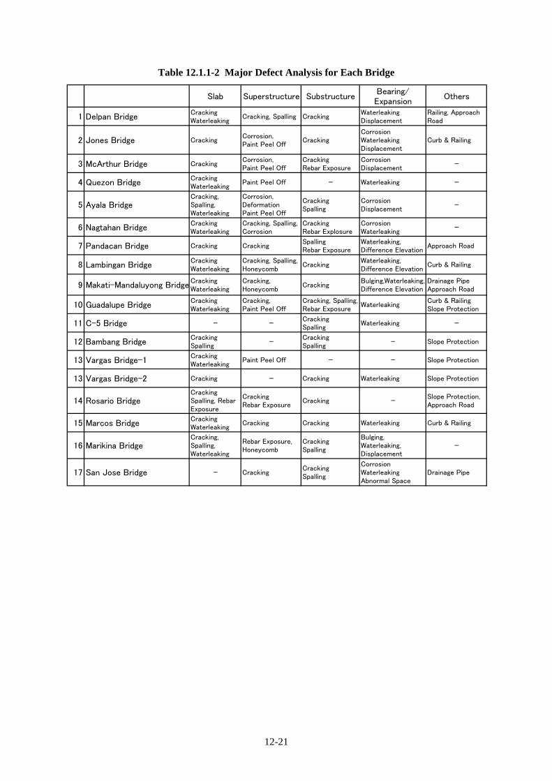
Table 12.1.1-2 Major Defect Analysis for Each Bridge
Slab Superstructure SubstructureBearing/Expansion
Others
1 Delpan BridgeCrackingWaterleaking
Cracking, Spalling CrackingWaterleakingDisplacement
Railing, ApproachRoad
2 Jones Bridge CrackingCorrosion,Paint Peel Off
CrackingCorrosionWaterleakingDisplacement
Curb & Railing
3 McArthur Bridge CrackingCorrosion,Paint Peel Off
CrackingRebar Exposure
CorrosionDisplacement -
4 Quezon BridgeCrackingWaterleaking
Paint Peel Off - Waterleaking -
5 Ayala BridgeCracking,Spalling,Waterleaking
Corrosion,DeformationPaint Peel Off
CrackingSpalling
CorrosionDisplacement -
6 Nagtahan BridgeCrackingWaterleaking
Cracking, Spalling,Corrosion
CrackingRebar Explosure
CorrosionWaterleaking -
7 Pandacan Bridge Cracking CrackingSpallingRebar Exposure
Waterleaking,Difference Elevation
Approach Road
8 Lambingan BridgeCrackingWaterleaking
Cracking, Spalling,Honeycomb
CrackingWaterleaking,Difference Elevation
Curb & Railing
9 Makati-Mandaluyong BridgeCrackingWaterleaking
Cracking,Honeycomb
CrackingBulging,Waterleaking,Difference Elevation
Drainage PipeApproach Road
10 Guadalupe BridgeCrackingWaterleaking
Cracking,Paint Peel Off
Cracking, Spalling,Rebar Exposure
WaterleakingCurb & RailingSlope Protection
11 C-5 Bridge - -CrackingSpalling
Waterleaking -
12 Bambang BridgeCrackingSpalling -
CrackingSpalling - Slope Protection
13 Vargas Bridge-1CrackingWaterleaking
Paint Peel Off - - Slope Protection
13 Vargas Bridge-2 Cracking - Cracking Waterleaking Slope Protection
14 Rosario BridgeCrackingSpalling, RebarExposure
CrackingRebar Exposure
Cracking -Slope Protection,Approach Road
15 Marcos BridgeCrackingWaterleaking
Cracking Cracking Waterleaking Curb & Railing
16 Marikina BridgeCracking,Spalling,Waterleaking
Rebar Exposure,Honeycomb
CrackingSpalling
Bulging,Waterleaking,Displacement
-
17 San Jose Bridge - CrackingCrackingSpalling
CorrosionWaterleakingAbnormal Space
Drainage Pipe

12-22
Table 12.1.1-3 Global Evaluation for Bridge Seismic Performance in 1st Screening of Package-B (1/6) Max.Point
Construction Year 1965 Construction Year 1948 Construction Year 1948Seismic Design No Seismic Consideration Seismic Design No Seismic Consideration Seismic Design No Seismic Consideration
6 10 10AASHTO Standard Specification (8th Edition) was applied AASHTO Standard Specification (4th Edition) was applied AASHTO Standard Specification (4th Edition) was applied
Due to sharp skew (approx. 40°), bearings and expansion. Although it is old bridge, Steel girders are sturdy and sound Although it is old bridge, Steel girders are sturdy soundjoints are damaged that is caused waterleaking steel girders are except partially corrosion. But bearings are displaced and except partially corrosion. But bearings are displaced andcorroded and concrete box girders are severe cracking on corroded that is caused by waterleaking due to damaged corroded that is caused by waterleaking due to damagedbottom slab. and displaced expansion joints. and displaced expansion joints.
Rating Score 45 Rating Score 36 Rating Score 36
Bridge is located in port area and road to access to Bridge is located on arterial road to connect south and Bridge is located on arterial road to connect south andport. (Very Important) north. (Important) north. (Important)a: Minimum Required Seating Length (AASHTO) : 55cm a: Minimum Required Seating Length (AASHTO) : 47cm a: Minimum Required Seating Length (AASHTO) : 49cmb: Minimum Required Seating Length (JRA): 98cm 0 b: Minimum Required Seating Length (JRA): 87cm b: Minimum Required Seating Length (JRA): 90cmExisting Seating Length (N) : 130cm Existing Seating Length (N) : 90cm Existing Seating Length (N) : 120cmLongitudinal restrainers were installed but some of them Longitudinal restrainers are not provided but bridge is Longitudinal restrainers are not provided but bridge is aare stolen and not sufficient functions. Bearings on 10 Continuous Steel I-girder and lateral movement is restricted 4 Continuous Steel I-girder and lateral movement is restricted 4sharp skew bridge are provided with prevention works by concrete blocks. by concrete blocks.Continuous Concrete Box Girder (new) Continuous Steel I- Girder Bridge Continuous Steel I- Girder BridgeContinuous Steel I- Girder (old)
Liquefaction Potential : High 10 Liquefaction Potential : High 10 Liquefaction Potential : High 10
5 5 5
Traffic disturbance and noise & pollution are considered for Traffic disturbance and noise & pollution are considered for Traffic disturbance and noise & pollution are considered forimpact of environment. 3 impact of environment. impact of environment. 3
Delpan Bridge, which has sharp skew, is vulnerable to seismic To maintain sturdy vintage steel bridge, expansion joins are To maintain sturdy vintage steel bridge, expansion joins areforce. Global earthquake resistant examination is required urgently repaired (replaced) to stop waterleaking. Steel repaired because no space between steel girders andespecially for bearing system and fall prevent apparatus. bearings are properly maintained and protect from water and abutment. Steel girders are deformed by overstress due to
dust and seismic lateral force with some stoppers temperature. Repaint is urgently required.
5
20ton 20ton 0
44
9
33
9
10
10 00
(JRA Classification : Type-III)
10
Phys
ical
Fac
tors
(50)
Bridge Importance 5
Conditions of BridgeBased on Visual
Inspection30
Construction Age &Applied DesignSpecification
Loading Capacity 5
18
AASHTO Classification : Type-IV
Seating Length
Fall Prevent Apparatus
Liquefaction 10
AASHTO Classification : Type-IV
10
5Soil Classification
Type of Bridge
3
L=26.5+46.0+57.6+46.0+26.65=202.8m, W=20.52m L=35.5+43.4+35.5=114.4m, W=21.2m
(JRA Classification : Type-II) (JRA Classification : Type-III)
4
020ton 0
48
Evaluation Items
Side /Under/ On the road view
Geogr
aphic
al F
acto
rs(2
0)
61100
Impact to Environment
Evaluation
5
Seis
mic
Perf
orm
ance
48
Jones Bridge McArthur BridgeDelpan Bridge
L=37.3+40.3+37.0=114.6m, W=21.2m
Candidate for the Second Screening (Retrofitting)
AASHTO Classification : Type-IV
Urgent Maintenance Urgent Maintenance

12-23
Table 12.1.1-4 Global Evaluation for Bridge Seismic Performance in 1st Screening of Package-B (2/6) Max.Point
Construction Year 1946 Construction Year 1950 Construction Year 1966Seismic Design No Seismic Consideration Seismic Design No Seismic Consideration Seismic Design Seismic Design Force
10 10 6AASHTO Standard Specification (4th Edition) was applied AASHTO Standard Specification (4th Edition) was applied AASHTO Standard Specification (8th Edition) was applied
Although it is old bridge, Steel girders are sturdy sound As navigation clearance is low, steel members are severely Although it is old bridge, Steel girders are sturdy sound except partially corrosion. But expansions caused by damaged due to impact of ships. Truss members are small except partially corrosion. Overall steel members are paintwaterleaking are repaired urgently. inertia is that section loss due to corrosion are observed. peel off and corrosion is started soon. At approach bridges,
Deck slab, bearings and expansion joints are damaged. cracking on deck slab and girders are severely occurred.Rating Score 21 Rating Score 57 Rating Score 43
Bridge is located on arterial road to connect Malate and Bridge is located near Malacanang Palace and a political Bridge is located on Quirino Avenue in C2 ( Very Important)Quezon cities. (Very Important) road. (Very Important)a: Minimum Required Seating Length (AASHTO) : 71cm a: Minimum Required Seating Length (AASHTO) : 57cm a: Minimum Required Seating Length (AASHTO) : 52cmb: Minimum Required Seating Length (JRA): 121cm 0 b: Minimum Required Seating Length (JRA): 107cm 6 b: Minimum Required Seating Length (JRA): 92cm 0Existing Seating Length (N) : -cm (Visual Measurement) Existing Seating Length (N) : 80cm Existing Seating Length (N) : 100cmLongitudinal restrainers are not provided but Truss Retrofitting works for bridge fall are done in 1999 but some of Prevention works for bridge fall are installed at both approachtyped Arch is very low risk falling down. 4 them are broken or not sufficient functions. 10 bridges. Main bridge, which is a continuous truss bridge, is 6
very low risk falling down.Arched Truss Bridge Single Span Truss Bridge Continuous Steel Truss Bridge
Liquefaction Potential : High 10 Liquefaction Potential : High 10 Liquefaction Potential : High 10
3 5 3
Traffic disturbance and is considered for impact of Resettlement of building & inhabitant, traffic disturbance, Traffic disturbance, noise & pollution and politically restrictedenvironment 2 Noise &pollution and politically restricted area are 5 area are considered for impact of environment. 5
considered for impact of environment.To maintain sturdy vintage steel bridge, continuous and Reconstruction is recommended because old truss bridge To maintain sturdy vintage steel bridge, repainting for main periodical maintenance is necessary. Especially repainting is is not enough navigation clearance and ductility for seismic truss bridge and expel of squatters are urgently required.recommended. force. However, reconstruction of bridge has been funded Inspection & Maintenance of approach bridges are difficult
by local fund so excluded from the second screening. and safety for inhabitant is not secured in earthquake.
4
5 5
15ton 20ton2
6 10
Seis
mic
Perf
orm
ance 10
Fall Prevent Apparatus 10
Type of Bridge 10
Seating Length
Evaluation 100
Geogr
aphic
al F
acto
rs(2
0)
Liquefaction 10
Soil Classification 5
Impact to Environment 5
AASHTO Classification : Type-III AASHTO Classification : Type-IV AASHTO Classification : Type-III(JRA Classification : Type-II) (JRA Classification : Type-III) (JRA Classification : Type-II)
57
Continuous Maintenance Reconstruction by Local Funds Candidate for the Second Screening (retrofitting)
51 93
18
Construction Age &Applied DesignSpecification
10
Conditions of BridgeBased on Visual
Inspection30
L=61.56+73.65+(4.26)=139.47m, W=25.35m L=45.6+57.73+45.6=148.93m, W=24.7m
Bridge Importance 5
Loading Capacity
5
02
9 30
Ayala Bridge Nagtahan Bridge
Phys
ical
Fac
tors
(50)
15ton5
Evaluation Items Quezon Bridge
Side /Under/ On the road view
L=102.4m, W=21.9m

12-24
Table 12.1.1-5 Global Evaluation for Bridge Seismic Performance in 1st Screening of Package-B (3/6)
Max.Point
Construction Year 1977 Construction Year 1975 Construction Year 1986Seismic Design Seismic Design Force Seismic Design Seismic Design Force Seismic Design Seismic Design Force
6 6 6AASHTO Standard Specification (11th Edition) was applied AASHTO Standard Specification (11th Edition) was applied AASHTO Standard Specification (13th Edition) was applied
Cracklings are observed on deck slab, PC girders, abutments Serious shear cracks are detected on hinge connection Many cracking including shear cracks are detected on boxand piers partially. Re-bar exposure due to impact of ship is of PC girders. Cracking on deck slab of PC girders are girders, especially end portion. Lubber bearing pads aredetected on pier but not serious. mostly all observed on the bottom side. Waterleaking from bulging so that gap is occurred at expansion joints.
the damaged expansion joints are observed. Waterleaking from cracks are observed partially.Rating Score 20 Rating Score 46 Rating Score 39
Bridge is located on Paco-Sta. Mesa Rd, is a detour of Bridge is located on New Panaderos Road. (Important) Bridge is located on road to connect Makati andNagtahan Br. (Important) Mandaluyong cities. (Important)a: Minimum Required Seating Length (AASHTO) : 52cm a: Minimum Required Seating Length (AASHTO) : 52cm a: Minimum Required Seating Length (AASHTO) :52cmb: Minimum Required Seating Length (JRA): 93cm 0 b: Minimum Required Seating Length (JRA): 92cm 10 b: Minimum Required Seating Length (JRA): 92cm 6Existing Seating Length (N) : 100cm Existing Seating Length (N) : 50cm Existing Seating Length (N) : 80cmLongitudinal restrainers are not provided but Longitudinal restrainers are not provided at hinge portions. Longitudinal restrainers are not provided at hinge portions.lateral movement is restricted by concrete blocks. 6 Lateral movement is restricted by concrete blocks. 10 Lateral movement is restricted by concrete blocks. 4
At hinge portion, risk falling down is very high. At hinge portion, prevention apparatus should be provided.Single Span PC I-girder Single Span PC I-girder with Hinge Connection Single Span PC I-girder and Concrete Box girder with
Hinge Connection
Liquefaction Potential : High 10 Liquefaction Potential : Moderate 6 Liquefaction Potential : Moderate 6
2 3 3
Traffic disturbance is considered for impact of environment. Resettlement of building & inhabitant, traffic disturbance, Traffic disturbance is considered for impact of environment2 and noise & pollution are considered for impact of 5 2
environment.Bridge is relatively good condition and to continue periodical Irregular span proportion and hinge connection at center span Severe cracking on box girders is urgently maintained andmaintenance especially for cracking. Since longitudinal fall are very vulnerable for large earthquake. At bridge crossing lubber pads ruptured are replaced to adjust uneven level ofprevent apparatus is not provided, detail inspection is required point, river course makes a tight curve so bridge should be carriageway.in the second screening. crossing with one span to prevent impact of ship. At Center
span, quite a large deflection is observed even in visual.
1010 10
Seis
mic
Perf
orm
ance 10
Fall Prevent Apparatus 10
Type of Bridge 10
Seating Length
Evaluation 100
Geogr
aphic
al F
acto
rs(2
0)
Liquefaction 10
Soil Classification 5
Impact to Environment 5
AASHTO Classification : Type-II AASHTO Classification : Type-III AASHTO Classification : Type-III(JRA Classification : Type-I) (JRA Classification : Type-II) (JRA Classification : Type-II)
49
Fall Prevent Apparatus Candidate for the Second Screening (Reconstruction) Urgent Maintenance
39 73
L=30.0+50.0+30.0=110.0m, W=18.8m
Bridge Importance 5
Loading Capacity
0 18 9
Construction Age &Applied DesignSpecification
10
L=23.8+25.0+46.0+25.1+27.5=147.4m, W=16.6m
Conditions of BridgeBased on Visual
Inspection30
L=18.5+61.1+18.5=98.1m, W=24.0m
3 3 3
15ton 20ton0 2
Lambingan Bridge Makati-Mandaluyong Bridge
0Phys
ical
Fac
tors
(50
)
20ton5
Evaluation Items Pandacan Bridge
Side /Under/ On the road view

12-25
Table 12.1.1-6 Global Evaluation for Bridge Seismic Performance in 1st Screening of Package-B (4/6)
Max.Point
Construction Year 1962 Construction Year 1998 Construction Year 1991Seismic Design No seismic Consideration Seismic Design R-Factor Based Design Seismic Design Seismic Design Force
10 3 6AASHTO Standard Specification (11th Edition) was applied AASHTO LRFD Specification (1st Edition) was applied AASHTO Standard Specification (14th Edition) was applied
Serious shear cracks are detected on hinge connection of Some cracks on piers and waterleaking from a few Cracklings on deck slab and abutments and waterleaking PC girders. Cracking on deck slab are partially observed and expansion joints are observed but global bridge condition from cracks on deck slab are observed. Serious damages waterleaking are detected at several parts. Piers are in very good. due to erosion are detected on both side of slopeseverely damaged from impact of ships. protection.
Rating Score 51 Rating Score 9 Rating Score 22
Bridge is located on Epifanio de los Santos Avenue Bridge is located on Carlos P. Garcia Avenue in C-5 Bridge is located on M.Jimenez-P. Tuazon Road. in C-4 ( Very Important) 5 ( Very Important) 5 (Important) 3
a: Minimum Required Seating Length (AASHTO) : 52cm a: Minimum Required Seating Length (AASHTO) : 52cm a: Minimum Required Seating Length (AASHTO) : 49cmb: Minimum Required Seating Length (JRA): 88cm 10 b: Minimum Required Seating Length (JRA): 83cm 0 b: Minimum Required Seating Length (JRA): 90cm 6Existing Seating Length (N) : 50cm Existing Seating Length (N) : 120cm Existing Seating Length (N) : 60cmVertical restrainers are installed but not sufficient Longitudinal restrainers are not installed but bridge Longitudinal restrainers are not installed but bridgefunctions longitudinally. Especially, at hinge 10 is a continuous PC-girder, which is low risk falling down. 0 is a continuous PC-girder, which is low risk falling down. 0portion, risk falling down is very high. Lateral movement is restricted by concrete blocks. Lateral movement is restricted by concrete blocks.Continuous Steel Truss Bridge Continuous PC I-girder Bridge Continuous PC I-girder BridgeSingle Span PC I-girder with Hinge Connection
Liquefaction Potential : Low 3 Liquefaction Potential : Moderate 6 Liquefaction Potential : Moderate 6
2 3 3
Resettlement of buildings and inhabitants, traffic disturbance Traffic disturbance and is considered for impact of Traffic disturbance and is considered for impact of and noise & pollution are considered for impact of 5 environment 2 environment 2environment.Fatal shear cracks are occurred at hinge portion of center Bridge is relatively good condition and to continue periodical Bridge is relatively good condition and to continue periodicalspan. Severe crackings are also detected on deck slab and maintenance especially for cracking and damaged railing due maintenance especially for cracking and erosion of slopePC girders, some of which are accompanied with waterleaking. to impact of car. protection of left abutment.Piers are damaged due to impact of ship.
410
Fall Prevent Apparatus 10
Seis
mic
Perf
orm
ance
Phys
ical
Fac
tors
(50)
Evaluation 100
Geogr
aphic
al F
acto
rs(2
0)
Liquefaction 10
Soil Classification 5
Type of Bridge
AASHTO Classification : Type-II AASHTO Classification : Type-III
10
AASHTO Classification : Type-III
4
(JRA Classification : Type-I) (JRA Classification : Type-II) (JRA Classification : Type-II)
39
Candidate for Second Screening (Partial Reconstruction) Continuous Maintenance Continuous Maintenance
85 23
Impact to Environment 5
Construction Age &Applied DesignSpecification
10
Bridge Importance 5
Loading Capacity 5
Seating Length 10
Side /Under/ On the road view
L=35.7+42.8+35.94=144.44m, W=25.4m
020ton
Conditions of BridgeBased on Visual
Inspection30 30
L=24.85+24.95+25.0+25.85+45.88+22.21+26.95+26.7+26.45=272.96m, W=27.7m L=(12.0+11.65+11.7)+(25.9+40.19+25.93)+(12.15+11.95+11.85)=163.32m, W=10.35m
0020ton 20ton
90
Evaluation Items Guadalupe Bridge C-5 Bridge Bambang Bridge

12-26
Table 12.1.1-7 Global Evaluation for Bridge Seismic Performance in 1st Screening of Package-B (5/6)
Max.Point
Side View Side View Side View
Under View On the Road View Under View On the Road View Under View On the Road View
Construction Year 1973 Construction Yea 1992 Construction Year 1952Seismic Design Seismic Design Force Seismic Design Seismic Design Force Seismic Design Seismic Design Force
6 6 10AASHTO Standard Specification (10th Edition) was applied AASHTO Standard Specification (14th Edition) was applied AASHTO Standard Specification (5th Edition) was applied
Cracklings on deck slab and waterleaking from cracks on Some cracks on piers and waterleaking from a few Cracklings on deck slab and PC girders and waterleaking deck slab are observed. Paint peel off is observed on entire expansion joints are observed but global bridge condition from cracks on deck slab are observed. Re-bar exposuressteel girder plate. in very good. are detected at the deep spalling. Serious damages due to
erosion are detected on both side of slope protection.Rating Score 18 Rating Score 15 Rating Score 35
Bridge is located on arterial road to connect Pasig city Bridge is located on arterial road to connect Pasig city Bridge is located on Ortigas Avenue. (Important)and C-5. (Very Important) and C-5. (Very Important)a: Minimum Required Seating Length (AASHTO) : 43cm a: Minimum Required Seating Length (AASHTO) : 49cm a: Minimum Required Seating Length (AASHTO) : 48cmb: Minimum Required Seating Length (JRA): 95cm 6 b: Minimum Required Seating Length (JRA): 87cm 6 b: Minimum Required Seating Length (JRA): 85cm 0Existing Seating Length (N) : 70cm Existing Seating Length (N) : 80cm Existing Seating Length (N) : 100cmPrevention works for bridge fall were installed but all of Prevention works for bridge fall are not installed but bridge Longitudinal restrainers are provided fixing with substructurethem are stolen and not sufficient functions. 10 is a continuous PC-girder, which is low risk falling down. 0 and lateral movement is restricted by concrete blocks 0Lateral movement is restricted by concrete blocks. Lateral movement is restricted by concrete blocks.Continuous Steel I-Girder Bridge Continuous PC Girder Bridge Simple PC I-girder Bridge
Liquefaction Potential : Moderate 6 Liquefaction Potential : Moderate 6 Liquefaction Potential : Moderate 6
3 3 3
Traffic disturbance and is considered for impact of Traffic disturbance and is considered for impact of Traffic disturbance and is considered for impact of environment 2 environment 2 environment 2
Bridge is relatively good condition and to continue periodical Bridge is relatively good condition and to continue periodical Bridge is relatively good condition and to continue periodicalmaintenance especially for repainting on steel girders, slope maintenance especially for crackings and spallings on deck maintenance. but especially for crackings on deck slab andprotection eroded by strong flood and cracks accompanied. slab and piers and slope protection eroded by strong flood. piers and waterleaking from expansion joints are urgentlywith waterleaking. repaired.
0 9
104 4
5 35
Seis
mic
Perf
orm
ance
10
Fall Prevent Apparatus 10
Type of Bridge 10
Seating Length
Evaluation 100
Geogr
aphic
al F
acto
rs(2
0)
Liquefaction 10
Soil Classification 5
Impact to Environment 5
AASHTO Classification : Type-III AASHTO Classification : Type-III AASHTO Classification : Type-III(JRA Classification : Type-II) (JRA Classification : Type-II) (JRA Classification : Type-II)
43
Continuous Maintenance Continuous Maintenance Urgent Maintenance
42 32
5
Constructions Age &Applied DesignSpecification
10
Condition of BridgeBased on Visual
Inspection30
Vargas Bridge - 2 Rosario Bridge
0020ton 20ton
Side /Under/ On the road view
L=30.62+30.83+50.7+30.65=142.8m, W=8.9m
Loading capacity
L=19.3+30.5+50.6+22.04=122.44m, W=8.72m L=25.5+31.2+31.19+30.98+31.07+25.41=175.35m, W=28.34m
Phys
ical
Fac
tors
(50)
Evaluation Items Vargas Bridge - 1
0
Bridge Importance 5
0
20ton

12-27
Table 12.1.1-8 Global Evaluation for Bridge Seismic Performance in 1st Screening of Package-B (6/6)
Max.Point
Construction Year 1978 Construction Year 1980 Construction Year 1980Seismic Design Seismic Design Force Seismic Design Seismic Design Force Seismic Design Seismic Design Force
6 6 6AASHTO Standard Specification (11th Edition) was applied AASHTO Standard Specification (12th Edition) was applied AASHTO Standard Specification (12th Edition) was applied
Cracklings on deck slab and piers and waterleaking from Serious cracklings on deck slab and piers and waterleaking Cracking & Scaling on PC girders and piers are observed.cracks on deck slab are observed. Displacement of from cracks on deck slab are observed. Spallings on Steel bearings are severely corroded due to waterleaking fromexpansion joints are detected. concrete of deck slab and pier and re-bar exposure on PC girder from expansion joints. Local scoring is occurred around
girders and piers are detected. Bearings are damaged. piers.Rating Score 26 Rating Score 42 Rating Score 36
Bridge is located on Marcos Highway. (Important) Bridge is located on highway to connect Marikina and Bridge is located on E.. Rodrigues Avenue in commercialQuezon cities. (Important) area. (Important)
a: Minimum Required Seating Length (AASHTO) : 48cm a: Minimum Required Seating Length (AASHTO) : 48cm a: Minimum Required Seating Length (AASHTO) : 47cmb: Minimum Required Seating Length (JRA): 85cm 6 b: Minimum Required Seating Length (JRA): 85cm 6 b: Minimum Required Seating Length (JRA): 82cm 6Existing Seating Length (N) : 53cm Existing Seating Length (N) : 65cm Existing Seating Length (N) : 70cmLongitudinal restrainers are provided but some are stolen All piers are retrofitted with steel pipes. Fall prevent Longitudinal restrainers are not provided longitudinally Lateral movement is restricted by concrete blocks 6 apparatus for superstructure are not provided longitudinally 10 and laterally. 10
and laterallySingle span PC I-Girder Bridge Single span PC I-Girder Bridge Single span PC I-Girder Bridge
Liquefaction Potential : Moderate 6 Liquefaction Potential : Moderate 6 Liquefaction Potential : Low 3
3 3 2
Traffic disturbance and is considered for impact of Traffic disturbance and noise & pollution are considered Traffic disturbance and is considered for impact of environment 2 for impact of environment. 3 environment 2
Bridge is relatively good condition and to continue periodical Bridge is fairly damaged on deck slab and PC girders so that Bridge is relatively good condition and to continue periodicalmaintenance. but especially for the stolen longitudinal concrete material test related to deterioration is required to maintenance especially for cracking and scoring . Sincerestrainers are urgently reinstalled and maintain properly. check vulnerability. Fall prevent apparatus shall be provided longitudinal fall prevent apparatus is not provided, detail
for both longitudinally and laterally. inspection is required in the second screening.
L=22.03+30.0+27.5+30.15+6x30.0+22.0=311.68m, W=19.7m
9Conditions of Bridge
Based on VisualInspection
30 9 18
L=24.9+24.97+24.95+24.97+25.0+24.97+24.96+24.95=199.67m, W=19.1m
Construction Age &Applied DesignSpecification
10
020ton5 20ton 20ton0 0
10
(JRA Classification : Type-II)
10
Seis
mic
Perf
orm
ance 10
Fall Prevent Apparatus 10
Type of Bridge 10
Seating Length
Evaluation 100
Geogr
aphic
al F
acto
rs(2
0)
Liquefaction 10
Soil Classification 5
Impact to Environment 5
51
Urgent Maintenance Candidate for the Second Screening ( Retrofitting) Fall Prevent Apparatus
51 65
AASHTO Classification : Type-II(JRA Classification : Type-II)
Phys
ical
Fac
tors
(50)
Bridge Importance 5
Loading capacity
(JRA Classification : Type-I)AASHTO Classification : Type-III AASHTO Classification : Type-III
10
3 3 3
Evaluation Items Marcos Bridge Marikina Bridge San Jose Bridge
Side /Under/ On the road view
L=24.2+3x30.0+24.0=138.2m, W=20.3m

12-28
12.1.2 Selection of Target Bridges for the Second Screening
The results of the First Screening of Package-B are summarized in Table 12.1.2-1. Out of 18 rated bridges shown in the Table, the following 8 bridges listed in Table 12.1.2-2 are selected for checking seismic performance in Package B. Rank No.1 is Ayala Bridge which will be financed by local fund so that it will be deleted from the candidates for the second screening. Rank No.2 to No.6 is selected as the candidates for the second screening through the detailed inspection. Recommended rehabilitation methods are preliminary selection in consideration with rating score. Two (2) reconstruction bridges for basic design in Package-B will be selected in the second screening. Both San Jose Bridge and Pandacan Bridge, which are simply supported bridges, do not have fall-down prevention apparatus. However, it is recommended that proper apparatus be installed to prevent girders falling during large earthquake.
Table 12.1.2-1 Selected Bridges for Checking Seismic Performance in Package-B
Rank Name of Bridge Score Recommended Rehabilitation Method
1 Ayala Bridge 93 Reconstruction by Local Fund
2 Guadalupe Bridge 85 Retrofitting
3 Lambingan Bridge 73 Retrofitting
4 Marikina Bridge 65 Retrofitting
5 Delpan Bridge 61 Retrofitting
6 Nagtahan Bridge 57 Retrofitting
7 San Jose Bridge 51 Fall Prevent Apparatus
16 Pandacan Bridge 39 Fall Prevent Apparatus
Candidate for the Second Screening

12-29
Table 12.1.2-2 Results of Rating Analysis in the 1st Screening
(10) (30) (5) (5) (10) (10) (10) (10) (5) (5) (100)
1 Delpan Bridge 6 18 0 5 0 10 4 10 5 3 61 Retrofitting
2 Jones Bridge 10 9 0 3 0 4 4 10 5 3 48 Urgent Maintenance
3 McArthur Bridge 10 9 0 3 0 4 4 10 5 3 48 Urgent Maintenance
4 Quezon Bridge 10 9 2 5 0 4 6 10 3 2 51 Continuous Maintenance
5 Ayala Bridge 10 30 2 5 6 10 10 10 5 5 93Reconstruction by LocalFund
6 Nagtahan Bridge 6 18 0 5 0 6 4 10 3 5 57 Urgent Maintenance
7 Pandacan Bridge 6 0 0 3 0 6 10 10 2 2 39 Fall Prevent Apparatus
8 Lambingan Bridge 6 18 2 3 10 10 10 6 3 5 73 Reconstruction
9 Makati-Manda. Bridge 6 9 0 3 6 4 10 6 3 2 49 Urgent Maintenance
10 Guadalupe Bridge 10 30 0 5 10 10 10 3 2 5 85 Partial Reconstruction
11 C-5 Bridge 3 0 0 5 0 0 4 6 3 2 23 Continuous Maintenance
12 Bambang Bridge 6 9 0 3 6 0 4 6 3 2 39 Continuous Maintenance
13 Vargas Bridge-1 6 0 0 5 6 10 4 6 3 2 42 Continuous Maintenance
13 Vargas Bridge-2 6 0 0 5 6 0 4 6 3 2 32 Continuous Maintenance
14 Rosario Bridge 10 9 0 3 0 0 10 6 3 2 43 Urgent Maintenance
15 Marcos Bridge 6 9 0 3 6 6 10 6 3 2 51 Urgent Maintenance
16 Marikina Bridge 6 18 0 3 6 10 10 6 3 3 65 Retrofitting
17 San Jose Bridge 6 9 0 3 6 10 10 3 2 2 51 Fall Prevent Apparatus
Recommended MethodConstruction Age &
Applied DesignSpecification
Conditions of BridgeBased on Visual
Inspection
SoilClassification
Impact toEnvironment
Name of Bridge LiquefactionNo.
TotalRating
Physical Factors (50) Geographical Factors (20)Seismic Performance Factors (30)
LoadingCapacity
BridgeImportance
SeatingLength
Fall PreventApparatus
Type ofBridge

12-30
12.2 Results of the First Screening for Package C
12.2.1 Results of the First Screening
(1) Results of the Bridge Soundness Survey
Bridge soundness survey was implemented based on the evaluation criteria for the first screening. The
results of the survey are shown as below.

12-31
1) Badiwan Bridge
H. STRUCTURAL CONDITIONS OF BRIDGE COMPONENTS
Good Fair Poor Bad0% 30% 60% 100%
(50) Deck Slab Concrete Cracking 10 ○ 0 (Primary) Exposure/Corrosion of Rebars 10 0
Scaling/Spalling 10 0Delamination 10 0Honeycomb 10 ○ 0Waterleaking 10 0
(51) Concrete Beam/ Cracking 10 0 Girder Exposure/Corrosion of Rebars 10 ○ 0 (Primary) Spalling, Scaling,Disintegration 10 0
Delamination 10 0Honeycomb 10 ○ 0Waterleaking 10 0
(52) Steel Beam/ Corrosion 10 0 Truss Members Cracking 10 0 (Bracings, etc.) Deformation/Buckling 10 0 (Primary) Abnormal Vibrations 10 0
Loose Connection 10 0Paint Peel off 10 0
(53) Shoe/Bearing Steel Corrosion 10 0Rubber Loose Connection 10 0
Abnormal Displacement 10 0Bulging/Rupture 10 0
(Primary) Bed (Support ) Damage 10 0(54) Abutments Concrete Settlement 10 0 (Primary) Masonry Movement 10 0
Others Delamination 10 0Scouring 10 0Spalling, Scaling,Disintegration 10 0Cracking concretre 10 0Exposure/Corrosion of Reinf. 10 0Honeycomb 10 0
(55) Piers Concrete Settlement 10 0 (Primary) Masonry Movement 10 0
Others Delamination 10 0Scouring 10 0Spalling, Scaling,Disintegration 10 0Cracking concrete 10 0Exposure/Corrosion of Reinf. 10 0Honeycomb 10 0
(56) Curb and Railing Concrete Cracking 5 0 (Secondary) Exposure/Corrosion of Reinf. 5 0
Spalling 5 0Impact Damaged 5 0 0
RemarksAccumrated
Rating ofdamage
0
0
0
Piers are coated with mortar;impossible to evaluate crackcondition.
0
Component MaterialType of Damages/
RatingScore
Rating ofdamage
Severity of Damage
Black stain by fire at the concrete boxgirder
0
0
PrestressedConcrete
ReinforcedConcrete
Bridge Member
Good Fair Poor Bad
0% 30% 60% 100%
(57) Expansion Joint Steel Waterleaking 10 ○ 10 (Primary) Others Abnormal Space/Noise 10 0
Difference in elevation 10 0Displacement 10 0Cracking/Rupture 10 ○ 3
(58) Painting Cond. Discoloration 10 0 (Primary) Rust 10 0
Exfoliation 10 0(59) Drainage Pipe PVC Clogged 5 ○ 2 (Secondary) Steel Cracks 5 0
Others (60) Slope Protection Gabions Settlement 5 0 (Secondary) Others Erossion 5 0
Scouring 5 0Cracks 5 0Others
(61) Approach Road Concrete Cracking 5 0 (Secondary) Asphalt Pot-holes 5 0
Others (62) River Condition Scouring 5 0 (Secondary) Sedimentation 5 ○ 0
Others
(63) Total Condition Rating 540 15
RatingScore
2
13
0
Remarks
Debris flow between P1& P2, P5 & P6
A1(R):Retaining WallA1(L):Masonry Embankment
・ No pipe under the drainage holes・ Small drainage holes;stuffed
Component Material
Bridge MemberType of Damages/
Severity of DamageRating ofdamage
AccumratedRating ofdamage
0
0
0

12-32
2) Buntun Bridge
H. STRUCTURAL CONDITIONS OF BRIDGE COMPONENTS
Good Fair Poor Bad0% 30% 60% 100%
(50) Deck Slab Concrete Cracking 10 ○ 0 (Primary) Exposure/Corrosion of Rebars 10 0
Scaling/Spalling 10 0Delamination 10 0Honeycomb 10 0Waterleaking 10 ○ 3
(51) Concrete Beam/ Cracking 10 0 Girder Exposure/Corrosion of Rebars 10 0 (Primary) Spalling, Scaling,Disintegration 10 0
Delamination 10 0Honeycomb 10 0Waterleaking 10 0
(52) Steel Beam/ Corrosion 10 0 Truss Members Cracking 10 0 (Bracings, etc.) Deformation/Buckling 10 ○ 0 (Primary) Abnormal Vibrations 10 ○ 6
Loose Connection 10 0Paint Peel off 10 0
(53) Shoe/Bearing Steel Corrosion 10 0Rubber Loose Connection 10 0
Abnormal Displacement 10 ○ 0Bulging/Rupture 10 0
(Primary) Bed (Support ) Damage 10 0(54) Abutments Concrete Settlement 10 0 (Primary) Masonry Movement 10 0
Others Delamination 10 0Scouring 10 0Spalling, Scaling,Disintegration 10 0Cracking concretre 10 0Exposure/Corrosion of Reinf. 10 0Honeycomb 10 0
(55) Piers Concrete Settlement 10 0 (Primary) Masonry Movement 10 0
Others Delamination 10 0Scouring 10 ○ 3Spalling, Scaling,Disintegration 10 0Cracking concrete 10 ○ 3Exposure/Corrosion of Reinf. 10 0Honeycomb 10 0
(56) Curb and Railing Concrete Cracking 5 0 (Secondary) Exposure/Corrosion of Reinf. 5 0
Spalling 5 0Impact Damaged 5 ○ 3 3
RemarksAccumrated
Rating ofdamage
0
0
6
6
Component MaterialType of Damages/
RatingScore
Rating ofdamage
Severity of Damage
3
0
PrestressedConcrete
ReinforcedConcrete
Bridge Member
Good Fair Poor Bad
0% 30% 60% 100%
(57) Expansion Joint Steel Waterleaking 10 ○ 10 (Primary) Others Abnormal Space/Noise 10 0
Difference in elevation 10 0Displacement 10 0Cracking/Rupture 10 0
(58) Painting Cond. Discoloration 10 0 (Primary) Rust 10 0
Exfoliation 10 0(59) Drainage Pipe PVC Clogged 5 0 (Secondary) Steel Cracks 5 0
Others (60) Slope Protection Gabions Settlement 5 0 (Secondary) Others Erossion 5 0
Scouring 5 0Cracks 5 ○ 2Others
(61) Approach Road Concrete Cracking 5 0 (Secondary) Asphalt Pot-holes 5 0
Others (62) River Condition Scouring 5 ○ 2 (Secondary) Sedimentation 5 0
Others
(63) Total Condition Rating 540 32
RatingScore
0
10
0
RemarksComponent Material
Bridge MemberType of Damages/
Severity of DamageRating ofdamage
AccumratedRating ofdamage
2
0
2

12-33
3) Lucban Bridge
H. STRUCTURAL CONDITIONS OF BRIDGE COMPONENTS
Good Fair Poor Bad0% 30% 60% 100%
(50) Deck Slab Concrete Cracking 10 0 (Primary) Exposure/Corrosion of Rebars 10 0
Scaling/Spalling 10 ○ 0Delamination 10 0Honeycomb 10 ○ 3Waterleaking 10 ○ 3
(51) Concrete Beam/ Cracking 10 0 Girder Exposure/Corrosion of Rebars 10 0 (Primary) Spalling, Scaling,Disintegration 10 0
Delamination 10 0Honeycomb 10 0Waterleaking 10 0
(52) Steel Beam/ Corrosion 10 ○ 3 Truss Members Cracking 10 0 (Bracings, etc.) Deformation/Buckling 10 0 (Primary) Abnormal Vibrations 10 0
Loose Connection 10 0Paint Peel off 10 ○ 3
(53) Shoe/Bearing Steel Corrosion 10 ○ 3Rubber Loose Connection 10 0
Abnormal Displacement 10 ○ 3Bulging/Rupture 10 0
(Primary) Bed (Support ) Damage 10 ○ 0(54) Abutments Concrete Settlement 10 0 (Primary) Masonry Movement 10 0
Others Delamination 10 0Scouring 10 0Spalling, Scaling,Disintegration 10 ○ 6Cracking concretre 10 0Exposure/Corrosion of Reinf. 10 0Honeycomb 10 0
(55) Piers Concrete Settlement 10 0 (Primary) Masonry Movement 10 0
Others Delamination 10 0Scouring 10 0Spalling, Scaling,Disintegration 10 0Cracking concrete 10 0Exposure/Corrosion of Reinf. 10 0Honeycomb 10 0
(56) Curb and Railing Concrete Cracking 5 ○ 3 (Secondary) Exposure/Corrosion of Reinf. 5 0
Spalling 5 0Impact Damaged 5 0 3
RemarksAccumrated
Rating ofdamage
6
6
0
6
Component MaterialType of Damages/
RatingScore
Rating ofdamage
Severity of Damage
6
0
PrestressedConcrete
ReinforcedConcrete
Bridge Member
Good Fair Poor Bad
0% 30% 60% 100%
(57) Expansion Joint Steel Waterleaking 10 ○ 10 (Primary) Others Abnormal Space/Noise 10 ○ 0
Difference in elevation 10 0Displacement 10 0Cracking/Rupture 10 0
(58) Painting Cond. Discoloration 10 0 (Primary) Rust 10 ○ 3
Exfoliation 10 ○ 3(59) Drainage Pipe PVC Clogged 5 0 (Secondary) Steel Cracks 5 0
Others (60) Slope Protection Gabions Settlement 5 0 (Secondary) Others Erossion 5 0
Scouring 5 0Cracks 5 ○ 3Others
(61) Approach Road Concrete Cracking 5 0 (Secondary) Asphalt Pot-holes 5 0
Others (62) River Condition Scouring 5 0 (Secondary) Sedimentation 5 0
Others
(63) Total Condition Rating 540 46
RatingScore
0
10
6
RemarksComponent Material
Bridge MemberType of Damages/
Severity of DamageRating ofdamage
AccumratedRating ofdamage
3
0
0
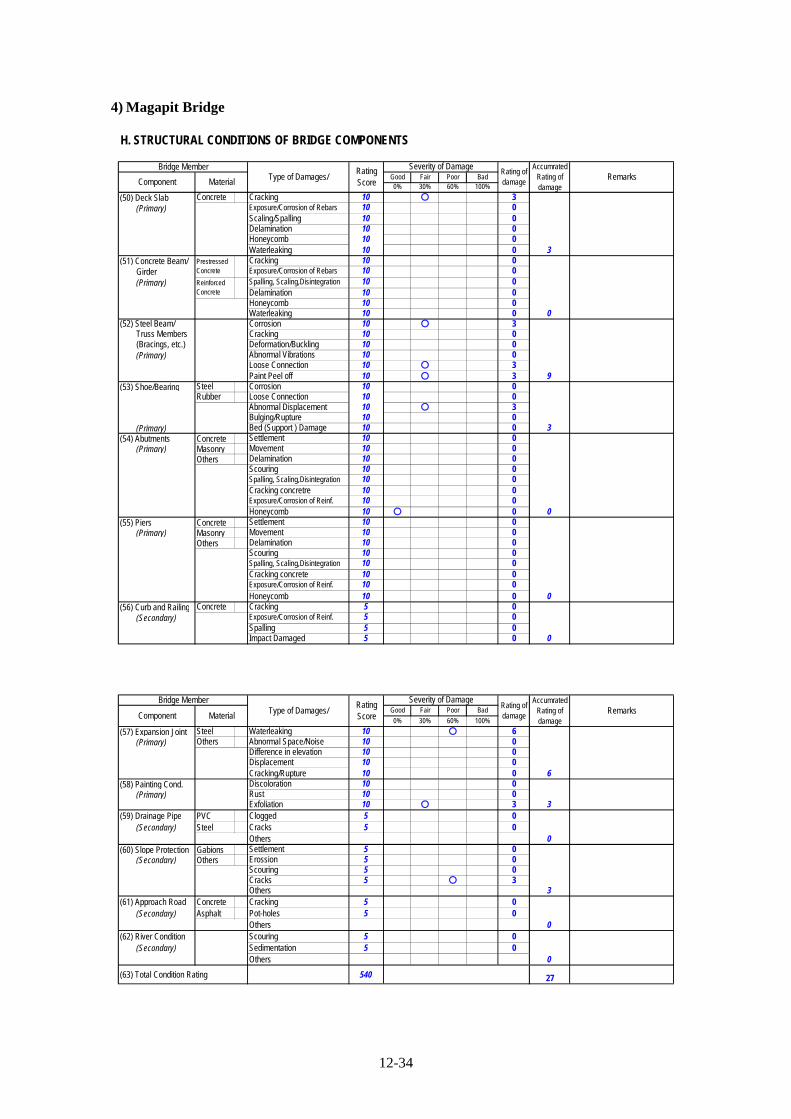
12-34
4) Magapit Bridge
H. STRUCTURAL CONDITIONS OF BRIDGE COMPONENTS
Good Fair Poor Bad0% 30% 60% 100%
(50) Deck Slab Concrete Cracking 10 ○ 3 (Primary) Exposure/Corrosion of Rebars 10 0
Scaling/Spalling 10 0Delamination 10 0Honeycomb 10 0Waterleaking 10 0
(51) Concrete Beam/ Cracking 10 0 Girder Exposure/Corrosion of Rebars 10 0 (Primary) Spalling, Scaling,Disintegration 10 0
Delamination 10 0Honeycomb 10 0Waterleaking 10 0
(52) Steel Beam/ Corrosion 10 ○ 3 Truss Members Cracking 10 0 (Bracings, etc.) Deformation/Buckling 10 0 (Primary) Abnormal Vibrations 10 0
Loose Connection 10 ○ 3Paint Peel off 10 ○ 3
(53) Shoe/Bearing Steel Corrosion 10 0Rubber Loose Connection 10 0
Abnormal Displacement 10 ○ 3Bulging/Rupture 10 0
(Primary) Bed (Support ) Damage 10 0(54) Abutments Concrete Settlement 10 0 (Primary) Masonry Movement 10 0
Others Delamination 10 0Scouring 10 0Spalling, Scaling,Disintegration 10 0Cracking concretre 10 0Exposure/Corrosion of Reinf. 10 0Honeycomb 10 ○ 0
(55) Piers Concrete Settlement 10 0 (Primary) Masonry Movement 10 0
Others Delamination 10 0Scouring 10 0Spalling, Scaling,Disintegration 10 0Cracking concrete 10 0Exposure/Corrosion of Reinf. 10 0Honeycomb 10 0
(56) Curb and Railing Concrete Cracking 5 0 (Secondary) Exposure/Corrosion of Reinf. 5 0
Spalling 5 0Impact Damaged 5 0
Bridge Member
3
0
PrestressedConcrete
ReinforcedConcrete
9
Component Material Type of Damages/RatingScore
Rating ofdamage
Severity of Damage
0
RemarksAccumrated
Rating ofdamage
3
0
0
Good Fair Poor Bad
0% 30% 60% 100%
(57) Expansion Joint Steel Waterleaking 10 ○ 6 (Primary) Others Abnormal Space/Noise 10 0
Difference in elevation 10 0Displacement 10 0Cracking/Rupture 10 0
(58) Painting Cond. Discoloration 10 0 (Primary) Rust 10 0
Exfoliation 10 ○ 3(59) Drainage Pipe PVC Clogged 5 0 (Secondary) Steel Cracks 5 0
Others (60) Slope Protection Gabions Settlement 5 0 (Secondary) Others Erossion 5 0
Scouring 5 0Cracks 5 ○ 3Others
(61) Approach Road Concrete Cracking 5 0 (Secondary) Asphalt Pot-holes 5 0
Others (62) River Condition Scouring 5 0 (Secondary) Sedimentation 5 0
Others
(63) Total Condition Rating 540 27
Type of Damages/Severity of Damage
Rating ofdamage
AccumratedRating ofdamage
3
0
0
Bridge Member
Component Material Remarks
6
3
RatingScore
0
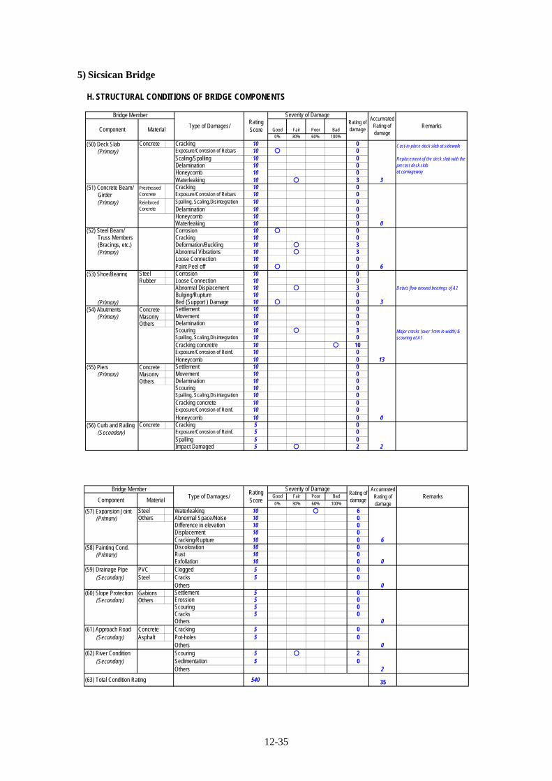
12-35
5) Sicsican Bridge
H. STRUCTURAL CONDITIONS OF BRIDGE COMPONENTS
Good Fair Poor Bad0% 30% 60% 100%
(50) Deck Slab Concrete Cracking 10 0 (Primary) Exposure/Corrosion of Rebars 10 ○ 0
Scaling/Spalling 10 0Delamination 10 0Honeycomb 10 0Waterleaking 10 ○ 3
(51) Concrete Beam/ Cracking 10 0 Girder Exposure/Corrosion of Rebars 10 0 (Primary) Spalling, Scaling,Disintegration 10 0
Delamination 10 0Honeycomb 10 0Waterleaking 10 0
(52) Steel Beam/ Corrosion 10 ○ 0 Truss Members Cracking 10 0 (Bracings, etc.) Deformation/Buckling 10 ○ 3 (Primary) Abnormal Vibrations 10 ○ 3
Loose Connection 10 0Paint Peel off 10 ○ 0
(53) Shoe/Bearing Steel Corrosion 10 0Rubber Loose Connection 10 0
Abnormal Displacement 10 ○ 3Bulging/Rupture 10 0
(Primary) Bed (Support ) Damage 10 ○ 0(54) Abutments Concrete Settlement 10 0 (Primary) Masonry Movement 10 0
Others Delamination 10 0Scouring 10 ○ 3Spalling, Scaling,Disintegration 10 0Cracking concretre 10 ○ 10Exposure/Corrosion of Reinf. 10 0Honeycomb 10 0
(55) Piers Concrete Settlement 10 0 (Primary) Masonry Movement 10 0
Others Delamination 10 0Scouring 10 0Spalling, Scaling,Disintegration 10 0Cracking concrete 10 0Exposure/Corrosion of Reinf. 10 0Honeycomb 10 0
(56) Curb and Railing Concrete Cracking 5 0 (Secondary) Exposure/Corrosion of Reinf. 5 0
Spalling 5 0Impact Damaged 5 ○ 2
RemarksComponent Material
3
Cast-in-place deck slab at sidewalk
Replacement of the deck slab with theprecast deck slabat carriageway
Bridge Member
Type of Damages/RatingScore
Severity of DamageRating ofdamage
AccumratedRating ofdamage
PrestressedConcrete
0
6
ReinforcedConcrete
3
Debris flow around bearings of A2
13
Major cracks (over 1mm in width) &scouring at A1
0
2
Good Fair Poor Bad
0% 30% 60% 100%
(57) Expansion Joint Steel Waterleaking 10 ○ 6 (Primary) Others Abnormal Space/Noise 10 0
Difference in elevation 10 0Displacement 10 0Cracking/Rupture 10 0
(58) Painting Cond. Discoloration 10 0 (Primary) Rust 10 0
Exfoliation 10 0(59) Drainage Pipe PVC Clogged 5 0 (Secondary) Steel Cracks 5 0
Others (60) Slope Protection Gabions Settlement 5 0 (Secondary) Others Erossion 5 0
Scouring 5 0Cracks 5 0Others
(61) Approach Road Concrete Cracking 5 0 (Secondary) Asphalt Pot-holes 5 0
Others (62) River Condition Scouring 5 ○ 2 (Secondary) Sedimentation 5 0
Others
(63) Total Condition Rating 540 35
RatingScoreComponent
AccumratedRating ofdamage
RemarksSeverity of Damage
Rating ofdamageMaterial
Bridge MemberType of Damages/
6
0
0
0
0
2

12-36
6) Bamban Bridge
H. STRUCTURAL CONDITIONS OF BRIDGE COMPONENTS
Good Fair Poor Bad0% 30% 60% 100%
(50) Deck Slab Concrete Cracking 10 0 (Primary) Exposure/Corrosion of Rebars 10 0
Scaling/Spalling 10 0Delamination 10 0Honeycomb 10 0Waterleaking 10 0
(51) Concrete Beam/ Cracking 10 0 Girder Exposure/Corrosion of Rebars 10 0 (Primary) Spalling, Scaling,Disintegration 10 0
Delamination 10 0Honeycomb 10 0Waterleaking 10 0
(52) Steel Beam/ Corrosion 10 ○ 3 Truss Members Cracking 10 0 (Bracings, etc.) Deformation/Buckling 10 0 (Primary) Abnormal Vibrations 10 0
Loose Connection 10 ○ 3Paint Peel off 10 0
(53) Shoe/Bearing Steel Corrosion 10 0Rubber Loose Connection 10 0
Abnormal Displacement 10 0Bulging/Rupture 10 0
(Primary) Bed (Support ) Damage 10 0(54) Abutments Concrete Settlement 10 0 (Primary) Masonry Movement 10 0
Others Delamination 10 0Scouring 10 0Spalling, Scaling,Disintegration 10 0Cracking concretre 10 ○ 3Exposure/Corrosion of Reinf. 10 0Honeycomb 10 0
(55) Piers Concrete Settlement 10 0 (Primary) Masonry Movement 10 0
Others Delamination 10 0Scouring 10 0Spalling, Scaling,Disintegration 10 0Cracking concrete 10 0Exposure/Corrosion of Reinf. 10 0Honeycomb 10 0
(56) Curb and Railing Concrete Cracking 5 0 (Secondary) Exposure/Corrosion of Reinf. 5 0
Spalling 5 0Impact Damaged 5 ○ 2
0
2
0
3
ReinforcedConcrete
6
Severity of DamageRating ofdamage
AccumratedRating ofdamage
PrestressedConcrete
0
RemarksComponent Material
0
Bridge Member
Type of Damages/RatingScore
Good Fair Poor Bad
0% 30% 60% 100%
(57) Expansion Joint Steel Waterleaking 10 0 (Primary) Others Abnormal Space/Noise 10 0
Difference in elevation 10 0Displacement 10 0Cracking/Rupture 10 0
(58) Painting Cond. Discoloration 10 0 (Primary) Rust 10 0
Exfoliation 10 0(59) Drainage Pipe PVC Clogged 5 0 (Secondary) Steel Cracks 5 0
Others (60) Slope Protection Gabions Settlement 5 0 (Secondary) Others Erossion 5 0
Scouring 5 0Cracks 5 0Others
(61) Approach Road Concrete Cracking 5 0 (Secondary) Asphalt Pot-holes 5 0
Others (62) River Condition Scouring 5 0 (Secondary) Sedimentation 5 0
Others
(63) Total Condition Rating 540 11
0
0
0
0
0
0
Severity of DamageRating ofdamageMaterial
Bridge MemberType of Damages/
AccumratedRating ofdamage
RemarksRatingScoreComponent

12-37
7) 1st Mandaue-Mactan Bridge
H. STRUCTURAL CONDITIONS OF BRIDGE COMPONENTS
Good Fair Poor Bad0% 30% 60% 100%
(50) Deck Slab Concrete Cracking 10 0 (Primary) Exposure/Corrosion of Rebars 10 ○ 3
Scaling/Spalling 10 0Delamination 10 0Honeycomb 10 0Waterleaking 10 ○ 3
(51) Concrete Beam/ Cracking 10 0 Girder Exposure/Corrosion of Rebars 10 0 (Primary) Spalling, Scaling,Disintegration 10 0
Delamination 10 0Honeycomb 10 0Waterleaking 10 0
(52) Steel Beam/ Corrosion 10 ○ 3 Truss Members Cracking 10 ○ 3 (Bracings, etc.) Deformation/Buckling 10 0 (Primary) Abnormal Vibrations 10 0
Loose Connection 10 0Paint Peel off 10 0
(53) Shoe/Bearing Steel Corrosion 10 ○ 0Rubber Loose Connection 10 0
Abnormal Displacement 10 0Bulging/Rupture 10 0
(Primary) Bed (Support ) Damage 10 ○ 0(54) Abutments Concrete Settlement 10 0 (Primary) Masonry Movement 10 0
Others Delamination 10 0Scouring 10 0Spalling, Scaling,Disintegration 10 0Cracking concretre 10 ○ 3Exposure/Corrosion of Reinf. 10 0Honeycomb 10 0
(55) Piers Concrete Settlement 10 0 (Primary) Masonry Movement 10 0
Others Delamination 10 0Scouring 10 ○ 0Spalling, Scaling,Disintegration 10 0Cracking concrete 10 0Exposure/Corrosion of Reinf. 10 ○ 10Honeycomb 10 0
(56) Curb and Railing Concrete Cracking 5 0 (Secondary) Exposure/Corrosion of Reinf. 5 0
Spalling 5 0Impact Damaged 5 0
10
0
0
3
ReinforcedConcrete
6
Severity of DamageRating ofdamage
AccumratedRating ofdamage
PrestressedConcrete
0
RemarksComponent Material
6
Rebar exposure due to spalling at theoverhanging deck slab (A2 side)
Bridge Member
Type of Damages/RatingScore
Good Fair Poor Bad
0% 30% 60% 100%
(57) Expansion Joint Steel Waterleaking 10 ○ 10 (Primary) Others Abnormal Space/Noise 10 0
Difference in elevation 10 0Displacement 10 0Cracking/Rupture 10 ○ 0
(58) Painting Cond. Discoloration 10 0 (Primary) Rust 10 0
Exfoliation 10 ○ 0(59) Drainage Pipe PVC Clogged 5 0 (Secondary) Steel Cracks 5 0
Others (60) Slope Protection Gabions Settlement 5 0 (Secondary) Others Erossion 5 0
Scouring 5 0Cracks 5 0Others
(61) Approach Road Concrete Cracking 5 0 (Secondary) Asphalt Pot-holes 5 0
Others (62) River Condition Scouring 5 0 (Secondary) Sedimentation 5 0
Others
(63) Total Condition Rating 540 35
0
0
0
10
0
0
Severity of DamageRating ofdamageMaterial
Bridge MemberType of Damages/
AccumratedRating ofdamage
RemarksRatingScoreComponent

12-38
8) Marcelo Ferman Bridge
H. STRUCTURAL CONDITIONS OF BRIDGE COMPONENTS
Good Fair Poor Bad0% 30% 60% 100%
(50) Deck Slab Concrete Cracking 10 0 (Primary) Exposure/Corrosion of Rebars 10 0
Scaling/Spalling 10 0Delamination 10 0Honeycomb 10 0Waterleaking 10 0
(51) Concrete Beam/ Cracking 10 0 Girder Exposure/Corrosion of Rebars 10 0 (Primary) Spalling, Scaling,Disintegration 10 0
Delamination 10 0Honeycomb 10 0Waterleaking 10 0
(52) Steel Beam/ Corrosion 10 0 Truss Members Cracking 10 0 (Bracings, etc.) Deformation/Buckling 10 0 (Primary) Abnormal Vibrations 10 0
Loose Connection 10 0Paint Peel off 10 0
(53) Shoe/Bearing Steel Corrosion 10 0Rubber Loose Connection 10 0
Abnormal Displacement 10 0Bulging/Rupture 10 0
(Primary) Bed (Support ) Damage 10 0(54) Abutments Concrete Settlement 10 0 (Primary) Masonry Movement 10 0
Others Delamination 10 0Scouring 10 0Spalling, Scaling,Disintegration 10 0Cracking concretre 10 0Exposure/Corrosion of Reinf. 10 0Honeycomb 10 0
(55) Piers Concrete Settlement 10 0 (Primary) Masonry Movement 10 0
Others Delamination 10 0Scouring 10 0Spalling, Scaling,Disintegration 10 0Cracking concrete 10 ○ 3Exposure/Corrosion of Reinf. 10 0Honeycomb 10 ○ 0
(56) Curb and Railing Concrete Cracking 5 0 (Secondary) Exposure/Corrosion of Reinf. 5 0
Spalling 5 0Impact Damaged 5 0
3
・ Hanycomb & cracks at piers・ Cracking at pylons(considered to be alkali ‐ aggregatereaction)
0
0
0
ReinforcedConcrete
0
Severity of DamageRating ofdamage
AccumratedRating ofdamage
PrestressedConcrete
0
RemarksComponent Material
0
Bridge Member
Type of Damages/RatingScore
Good Fair Poor Bad
0% 30% 60% 100%
(57) Expansion Joint Steel Waterleaking 10 ○ 10 (Primary) Others Abnormal Space/Noise 10 0
Difference in elevation 10 0Displacement 10 0Cracking/Rupture 10 ○ 6
(58) Painting Cond. Discoloration 10 0 (Primary) Rust 10 0
Exfoliation 10 0(59) Drainage Pipe PVC Clogged 5 0 (Secondary) Steel Cracks 5 0
Others (60) Slope Protection Gabions Settlement 5 0 (Secondary) Others Erossion 5 0
Scouring 5 0Cracks 5 0Others
(61) Approach Road Concrete Cracking 5 0 (Secondary) Asphalt Pot-holes 5 0
Others (62) River Condition Scouring 5 0 (Secondary) Sedimentation 5 0
Others
(63) Total Condition Rating 540 19
0
0
0
16
Uunder repair work by DPWH
0
0
Severity of DamageRating ofdamageMaterial
Bridge MemberType of Damages/
AccumratedRating ofdamage
RemarksRatingScoreComponent

12-39
9) Palanit Bridge
H. STRUCTURAL CONDITIONS OF BRIDGE COMPONENTS
Good Fair Poor Bad0% 30% 60% 100%
(50) Deck Slab Concrete Cracking 10 ○ 10 (Primary) Exposure/Corrosion of Rebars 10 ○ 3
Scaling/Spalling 10 ○ 10Delamination 10 0Honeycomb 10 0Waterleaking 10 ○ 6
(51) Concrete Beam/ Cracking 10 0 Girder Exposure/Corrosion of Rebars 10 0 (Primary) Spalling, Scaling,Disintegration 10 0
Delamination 10 0Honeycomb 10 0Waterleaking 10 0
(52) Steel Beam/ Corrosion 10 ○ 3 Truss Members Cracking 10 ○ 0 (Bracings, etc.) Deformation/Buckling 10 ○ 0 (Primary) Abnormal Vibrations 10 0
Loose Connection 10 0Paint Peel off 10 0
(53) Shoe/Bearing Steel Corrosion 10 ○ 3Rubber Loose Connection 10 0
Abnormal Displacement 10 0Bulging/Rupture 10 0
(Primary) Bed (Support ) Damage 10 0(54) Abutments Concrete Settlement 10 0 (Primary) Masonry Movement 10 0
Others Delamination 10 0Scouring 10 0Spalling, Scaling,Disintegration 10 0Cracking concretre 10 0Exposure/Corrosion of Reinf. 10 0Honeycomb 10 0
(55) Piers Concrete Settlement 10 0 (Primary) Masonry Movement 10 0
Others Delamination 10 0Scouring 10 0Spalling, Scaling,Disintegration 10 0Cracking concrete 10 0Exposure/Corrosion of Reinf. 10 0Honeycomb 10 0
(56) Curb and Railing Concrete Cracking 5 0 (Secondary) Exposure/Corrosion of Reinf. 5 0
Spalling 5 0Impact Damaged 5 0
0
0
3
0
ReinforcedConcrete
3
Main span
Severity of DamageRating ofdamage
AccumratedRating ofdamage
PrestressedConcrete
0
RemarksComponent Material
29
Bridge Member
Type of Damages/RatingScore
Good Fair Poor Bad
0% 30% 60% 100%
(57) Expansion Joint Steel Waterleaking 10 ○ 10 (Primary) Others Abnormal Space/Noise 10 0
Difference in elevation 10 0Displacement 10 0Cracking/Rupture 10 0
(58) Painting Cond. Discoloration 10 0 (Primary) Rust 10 0
Exfoliation 10 0(59) Drainage Pipe PVC Clogged 5 0 (Secondary) Steel Cracks 5 0
Others (60) Slope Protection Gabions Settlement 5 0 (Secondary) Others Erossion 5 0
Scouring 5 0Cracks 5 0Others
(61) Approach Road Concrete Cracking 5 0 (Secondary) Asphalt Pot-holes 5 0
Others (62) River Condition Scouring 5 0 (Secondary) Sedimentation 5 0
Others
(63) Total Condition Rating 540 45
0
0
0
10
0
0
Severity of DamageRating ofdamageMaterial
Bridge MemberType of Damages/
AccumratedRating ofdamage
RemarksRatingScoreComponent

12-40
10) Jibatang Bridge
H. STRUCTURAL CONDITIONS OF BRIDGE COMPONENTS
Good Fair Poor Bad0% 30% 60% 100%
(50) Deck Slab Concrete Cracking 10 0 (Primary) Exposure/Corrosion of Rebars 10 0
Scaling/Spalling 10 ○ 3Delamination 10 0Honeycomb 10 0Waterleaking 10 0
(51) Concrete Beam/ Cracking 10 0 Girder Exposure/Corrosion of Rebars 10 0 (Primary) Spalling, Scaling,Disintegration 10 0
Delamination 10 0Honeycomb 10 0Waterleaking 10 0
(52) Steel Beam/ Corrosion 10 ○ 6 Truss Members Cracking 10 0 (Bracings, etc.) Deformation/Buckling 10 0 (Primary) Abnormal Vibrations 10 0
Loose Connection 10 0Paint Peel off 10 0
(53) Shoe/Bearing Steel Corrosion 10 0Rubber Loose Connection 10 0
Abnormal Displacement 10 0Bulging/Rupture 10 0
(Primary) Bed (Support ) Damage 10 0(54) Abutments Concrete Settlement 10 0 (Primary) Masonry Movement 10 0
Others Delamination 10 0Scouring 10 0Spalling, Scaling,Disintegration 10 0Cracking concretre 10 0Exposure/Corrosion of Reinf. 10 0Honeycomb 10 ○ 6
(55) Piers Concrete Settlement 10 0 (Primary) Masonry Movement 10 0
Others Delamination 10 0Scouring 10 0Spalling, Scaling,Disintegration 10 ○ 6Cracking concrete 10 0Exposure/Corrosion of Reinf. 10 0Honeycomb 10 0
(56) Curb and Railing Concrete Cracking 5 ○ 0 (Secondary) Exposure/Corrosion of Reinf. 5 0
Spalling 5 0Impact Damaged 5 0
6
0
0
6
ReinforcedConcrete
6
Severity of DamageRating ofdamage
AccumratedRating ofdamage
PrestressedConcrete
0
RemarksComponent Material
3
Section loss due to spalling at the endof deck slab
Bridge Member
Type of Damages/RatingScore
Good Fair Poor Bad
0% 30% 60% 100%
(57) Expansion Joint Steel Waterleaking 10 ○ 6 (Primary) Others Abnormal Space/Noise 10 0
Difference in elevation 10 0Displacement 10 0Cracking/Rupture 10 ○ 3
(58) Painting Cond. Discoloration 10 0 (Primary) Rust 10 0
Exfoliation 10 0(59) Drainage Pipe PVC Clogged 5 0 (Secondary) Steel Cracks 5 0
Others (60) Slope Protection Gabions Settlement 5 0 (Secondary) Others Erossion 5 0
Scouring 5 0Cracks 5 ○ 2Others
(61) Approach Road Concrete Cracking 5 0 (Secondary) Asphalt Pot-holes 5 0
Others (62) River Condition Scouring 5 0 (Secondary) Sedimentation 5 0
Others
(63) Total Condition Rating 540 32
0
0
2
9
0
0
Severity of DamageRating ofdamageMaterial
Bridge MemberType of Damages/
AccumratedRating ofdamage
RemarksRatingScoreComponent
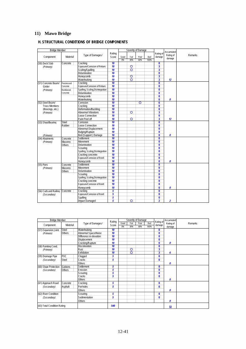
12-41
11) Mawo Bridge
H. STRUCTURAL CONDITIONS OF BRIDGE COMPONENTS
Good Fair Poor Bad0% 30% 60% 100%
(50) Deck Slab Concrete Cracking 10 0 (Primary) Exposure/Corrosion of Rebars 10 ○ 3
Scaling/Spalling 10 ○ 3Delamination 10 0Honeycomb 10 ○ 3Waterleaking 10 ○ 3
(51) Concrete Beam/ Cracking 10 0 Girder Exposure/Corrosion of Rebars 10 0 (Primary) Spalling, Scaling,Disintegration 10 0
Delamination 10 0Honeycomb 10 0Waterleaking 10 0
(52) Steel Beam/ Corrosion 10 ○ 6 Truss Members Cracking 10 0 (Bracings, etc.) Deformation/Buckling 10 0 (Primary) Abnormal Vibrations 10 ○ 3
Loose Connection 10 0Paint Peel off 10 ○ 3
(53) Shoe/Bearing Steel Corrosion 10 0Rubber Loose Connection 10 0
Abnormal Displacement 10 0Bulging/Rupture 10 0
(Primary) Bed (Support ) Damage 10 0(54) Abutments Concrete Settlement 10 0 (Primary) Masonry Movement 10 0
Others Delamination 10 0Scouring 10 0Spalling, Scaling,Disintegration 10 0Cracking concretre 10 0Exposure/Corrosion of Reinf. 10 0Honeycomb 10 0
(55) Piers Concrete Settlement 10 0 (Primary) Masonry Movement 10 0
Others Delamination 10 0Scouring 10 0Spalling, Scaling,Disintegration 10 0Cracking concrete 10 0Exposure/Corrosion of Reinf. 10 0Honeycomb 10 0
(56) Curb and Railing Concrete Cracking 5 0 (Secondary) Exposure/Corrosion of Reinf. 5 0
Spalling 5 0Impact Damaged 5 ○ 2
0
2
0
0
ReinforcedConcrete
12
Severity of DamageRating ofdamage
AccumratedRating ofdamage
PrestressedConcrete
0
RemarksComponent Material
12
Bridge Member
Type of Damages/RatingScore
Good Fair Poor Bad
0% 30% 60% 100%
(57) Expansion Joint Steel Waterleaking 10 0 (Primary) Others Abnormal Space/Noise 10 0
Difference in elevation 10 0Displacement 10 0Cracking/Rupture 10 0
(58) Painting Cond. Discoloration 10 0 (Primary) Rust 10 ○ 3
Exfoliation 10 ○ 3(59) Drainage Pipe PVC Clogged 5 0 (Secondary) Steel Cracks 5 0
Others (60) Slope Protection Gabions Settlement 5 0 (Secondary) Others Erossion 5 0
Scouring 5 0Cracks 5 0Others
(61) Approach Road Concrete Cracking 5 0 (Secondary) Asphalt Pot-holes 5 0
Others (62) River Condition Scouring 5 0 (Secondary) Sedimentation 5 0
Others
(63) Total Condition Rating 540 32
0
0
0
0
6
0
Severity of DamageRating ofdamageMaterial
Bridge MemberType of Damages/
AccumratedRating ofdamage
RemarksRatingScoreComponent

12-42
12) Biliran Bridge
H. STRUCTURAL CONDITIONS OF BRIDGE COMPONENTS
Good Fair Poor Bad0% 30% 60% 100%
(50) Deck Slab Concrete Cracking 10 0 (Primary) Exposure/Corrosion of Rebars 10 ○ 3
Scaling/Spalling 10 0Delamination 10 0Honeycomb 10 ○ 3Waterleaking 10 ○ 3
(51) Concrete Beam/ Cracking 10 0 Girder Exposure/Corrosion of Rebars 10 0 (Primary) Spalling, Scaling,Disintegration 10 0
Delamination 10 0Honeycomb 10 0Waterleaking 10 0
(52) Steel Beam/ Corrosion 10 ○ 3 Truss Members Cracking 10 0 (Bracings, etc.) Deformation/Buckling 10 ○ 0 (Primary) Abnormal Vibrations 10 0
Loose Connection 10 0Paint Peel off 10 0
(53) Shoe/Bearing Steel Corrosion 10 ○ 3Rubber Loose Connection 10 0
Abnormal Displacement 10 0Bulging/Rupture 10 0
(Primary) Bed (Support ) Damage 10 0(54) Abutments Concrete Settlement 10 0 (Primary) Masonry Movement 10 0
Others Delamination 10 0Scouring 10 0Spalling, Scaling,Disintegration 10 0Cracking concretre 10 0Exposure/Corrosion of Reinf. 10 0Honeycomb 10 0
(55) Piers Concrete Settlement 10 ○ 3 (Primary) Masonry Movement 10 0
Others Delamination 10 0Scouring 10 0Spalling, Scaling,Disintegration 10 0Cracking concrete 10 0Exposure/Corrosion of Reinf. 10 0Honeycomb 10 ○ 0
(56) Curb and Railing Concrete Cracking 5 0 (Secondary) Exposure/Corrosion of Reinf. 5 0
Spalling 5 0Impact Damaged 5 0
3
Settlement at P3
0
3
0
ReinforcedConcrete
3
Severity of DamageRating ofdamage
AccumratedRating ofdamage
PrestressedConcrete
0
RemarksComponent Material
9
Overhanging deck slab
Bridge Member
Type of Damages/RatingScore
Good Fair Poor Bad
0% 30% 60% 100%
(57) Expansion Joint Steel Waterleaking 10 0 (Primary) Others Abnormal Space/Noise 10 0
Difference in elevation 10 0Displacement 10 0Cracking/Rupture 10 0
(58) Painting Cond. Discoloration 10 0 (Primary) Rust 10 0
Exfoliation 10 0(59) Drainage Pipe PVC Clogged 5 0 (Secondary) Steel Cracks 5 0
Others (60) Slope Protection Gabions Settlement 5 0 (Secondary) Others Erossion 5 0
Scouring 5 0Cracks 5 0Others
(61) Approach Road Concrete Cracking 5 0 (Secondary) Asphalt Pot-holes 5 0
Others (62) River Condition Scouring 5 0 (Secondary) Sedimentation 5 0
Others
(63) Total Condition Rating 540 18
0
0
0
0
0
0
Severity of DamageRating ofdamageMaterial
Bridge MemberType of Damages/
AccumratedRating ofdamage
RemarksRatingScoreComponent

12-43
13) San Juanico Bridge
H. STRUCTURAL CONDITIONS OF BRIDGE COMPONENTS
Good Fair Poor Bad0% 30% 60% 100%
(50) Deck Slab Concrete Cracking 10 ○ 0 (Primary) Exposure/Corrosion of Rebars 10 0
Scaling/Spalling 10 0Delamination 10 0Honeycomb 10 ○ 0Waterleaking 10 ○ 6
(51) Concrete Beam/ Cracking 10 0 Girder Exposure/Corrosion of Rebars 10 0 (Primary) Spalling, Scaling,Disintegration 10 0
Delamination 10 0Honeycomb 10 0Waterleaking 10 0
(52) Steel Beam/ Corrosion 10 ○ 0 Truss Members Cracking 10 0 (Bracings, etc.) Deformation/Buckling 10 0 (Primary) Abnormal Vibrations 10 0
Loose Connection 10 0Paint Peel off 10 0
(53) Shoe/Bearing Steel Corrosion 10 0Rubber Loose Connection 10 0
Abnormal Displacement 10 0Bulging/Rupture 10 0
(Primary) Bed (Support ) Damage 10 0(54) Abutments Concrete Settlement 10 0 (Primary) Masonry Movement 10 0
Others Delamination 10 0Scouring 10 0Spalling, Scaling,Disintegration 10 0Cracking concretre 10 0Exposure/Corrosion of Reinf. 10 0Honeycomb 10 0
(55) Piers Concrete Settlement 10 0 (Primary) Masonry Movement 10 0
Others Delamination 10 0Scouring 10 0Spalling, Scaling,Disintegration 10 ○ 0Cracking concrete 10 0Exposure/Corrosion of Reinf. 10 0Honeycomb 10 0
(56) Curb and Railing Concrete Cracking 5 0 (Secondary) Exposure/Corrosion of Reinf. 5 0
Spalling 5 0Impact Damaged 5 0
0
Piers near sea water
0
0
0
ReinforcedConcrete
0
Seel members over the sea water
Severity of DamageRating ofdamage
AccumratedRating ofdamage
PrestressedConcrete
0
RemarksComponent Material
6
Overhanging deck slab
Bridge Member
Type of Damages/RatingScore
Good Fair Poor Bad
0% 30% 60% 100%
(57) Expansion Joint Steel Waterleaking 10 ○ 6 (Primary) Others Abnormal Space/Noise 10 0
Difference in elevation 10 0Displacement 10 0Cracking/Rupture 10 0
(58) Painting Cond. Discoloration 10 0 (Primary) Rust 10 0
Exfoliation 10 0(59) Drainage Pipe PVC Clogged 5 0 (Secondary) Steel Cracks 5 0
Others (60) Slope Protection Gabions Settlement 5 0 (Secondary) Others Erossion 5 0
Scouring 5 0Cracks 5 0Others
(61) Approach Road Concrete Cracking 5 0 (Secondary) Asphalt Pot-holes 5 0
Others (62) River Condition Scouring 5 0 (Secondary) Sedimentation 5 0
Others
(63) Total Condition Rating 540 12
0
0
0
6
0
0
Severity of DamageRating ofdamageMaterial
Bridge MemberType of Damages/
AccumratedRating ofdamage
RemarksRatingScoreComponent
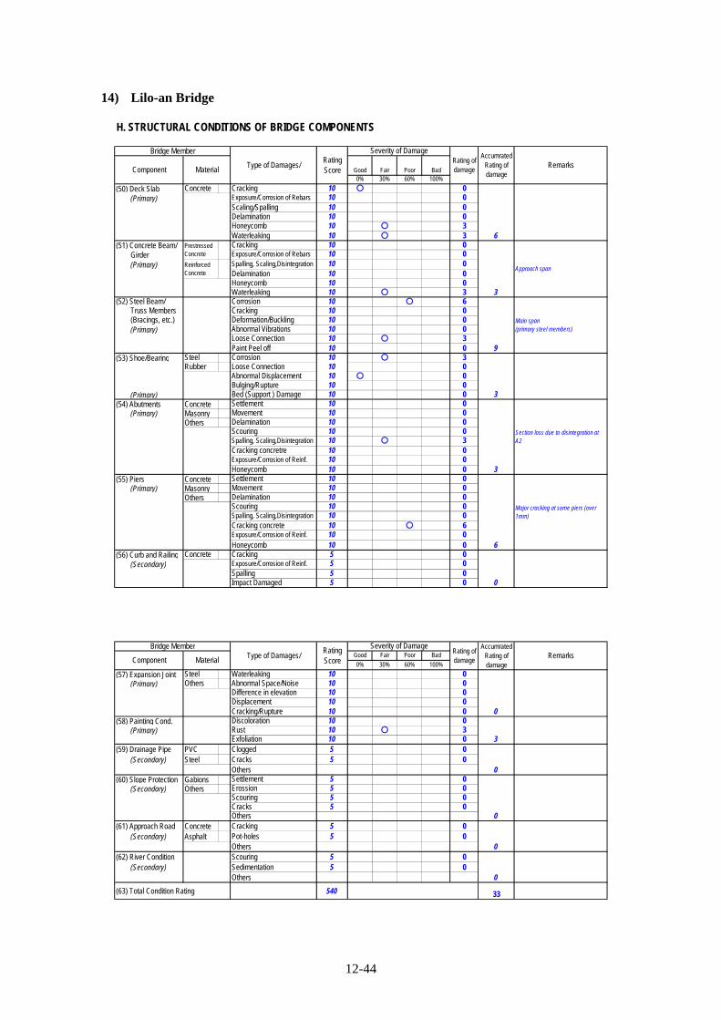
12-44
14) Lilo-an Bridge
H. STRUCTURAL CONDITIONS OF BRIDGE COMPONENTS
Good Fair Poor Bad0% 30% 60% 100%
(50) Deck Slab Concrete Cracking 10 ○ 0 (Primary) Exposure/Corrosion of Rebars 10 0
Scaling/Spalling 10 0Delamination 10 0Honeycomb 10 ○ 3Waterleaking 10 ○ 3
(51) Concrete Beam/ Cracking 10 0 Girder Exposure/Corrosion of Rebars 10 0 (Primary) Spalling, Scaling,Disintegration 10 0
Delamination 10 0Honeycomb 10 0Waterleaking 10 ○ 3
(52) Steel Beam/ Corrosion 10 ○ 6 Truss Members Cracking 10 0 (Bracings, etc.) Deformation/Buckling 10 0 (Primary) Abnormal Vibrations 10 0
Loose Connection 10 ○ 3Paint Peel off 10 0
(53) Shoe/Bearing Steel Corrosion 10 ○ 3Rubber Loose Connection 10 0
Abnormal Displacement 10 ○ 0Bulging/Rupture 10 0
(Primary) Bed (Support ) Damage 10 0(54) Abutments Concrete Settlement 10 0 (Primary) Masonry Movement 10 0
Others Delamination 10 0Scouring 10 0Spalling, Scaling,Disintegration 10 ○ 3Cracking concretre 10 0Exposure/Corrosion of Reinf. 10 0Honeycomb 10 0
(55) Piers Concrete Settlement 10 0 (Primary) Masonry Movement 10 0
Others Delamination 10 0Scouring 10 0Spalling, Scaling,Disintegration 10 0Cracking concrete 10 ○ 6Exposure/Corrosion of Reinf. 10 0Honeycomb 10 0
(56) Curb and Railing Concrete Cracking 5 0 (Secondary) Exposure/Corrosion of Reinf. 5 0
Spalling 5 0Impact Damaged 5 0
6
Major cracking at some piers (over1mm)
0
3
3
Section loss due to disintegration atA2
Approach spanReinforcedConcrete
9
Main span(primary steel members)
Severity of DamageRating ofdamage
AccumratedRating ofdamage
PrestressedConcrete
3
RemarksComponent Material
6
Bridge Member
Type of Damages/RatingScore
Good Fair Poor Bad
0% 30% 60% 100%
(57) Expansion Joint Steel Waterleaking 10 0 (Primary) Others Abnormal Space/Noise 10 0
Difference in elevation 10 0Displacement 10 0Cracking/Rupture 10 0
(58) Painting Cond. Discoloration 10 0 (Primary) Rust 10 ○ 3
Exfoliation 10 0(59) Drainage Pipe PVC Clogged 5 0 (Secondary) Steel Cracks 5 0
Others (60) Slope Protection Gabions Settlement 5 0 (Secondary) Others Erossion 5 0
Scouring 5 0Cracks 5 0Others
(61) Approach Road Concrete Cracking 5 0 (Secondary) Asphalt Pot-holes 5 0
Others (62) River Condition Scouring 5 0 (Secondary) Sedimentation 5 0
Others
(63) Total Condition Rating 540 33
0
0
0
0
3
0
Severity of DamageRating ofdamageMaterial
Bridge MemberType of Damages/
AccumratedRating ofdamage
RemarksRatingScoreComponent
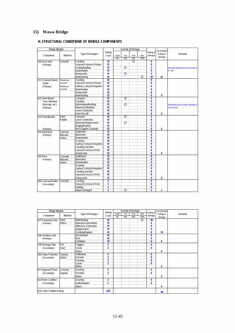
12-45
15) Wawa Bridge
H. STRUCTURAL CONDITIONS OF BRIDGE COMPONENTS
Good Fair Poor Bad0% 30% 60% 100%
(50) Deck Slab Concrete Cracking 10 ○ 6 (Primary) Exposure/Corrosion of Rebars 10 0
Scaling/Spalling 10 ○ 3Delamination 10 0Honeycomb 10 ○ 3Waterleaking 10 ○ 10
(51) Concrete Beam/ Cracking 10 0 Girder Exposure/Corrosion of Rebars 10 0 (Primary) Spalling, Scaling,Disintegration 10 0
Delamination 10 0Honeycomb 10 0Waterleaking 10 0
(52) Steel Beam/ Corrosion 10 ○ 3 Truss Members Cracking 10 0 (Bracings, etc.) Deformation/Buckling 10 ○ 3 (Primary) Abnormal Vibrations 10 0
Loose Connection 10 0Paint Peel off 10 0
(53) Shoe/Bearing Steel Corrosion 10 ○ 3Rubber Loose Connection 10 0
Abnormal Displacement 10 ○ 3Bulging/Rupture 10 0
(Primary) Bed (Support ) Damage 10 0(54) Abutments Concrete Settlement 10 0 (Primary) Masonry Movement 10 0
Others Delamination 10 0Scouring 10 0Spalling, Scaling,Disintegration 10 0Cracking concretre 10 0Exposure/Corrosion of Reinf. 10 0Honeycomb 10 0
(55) Piers Concrete Settlement 10 0 (Primary) Masonry Movement 10 0
Others Delamination 10 0Scouring 10 0Spalling, Scaling,Disintegration 10 0Cracking concrete 10 0Exposure/Corrosion of Reinf. 10 0Honeycomb 10 0
(56) Curb and Railing Concrete Cracking 5 0 (Secondary) Exposure/Corrosion of Reinf. 5 0
Spalling 5 0Impact Damaged 5 ○ 2
0
2
6
0
ReinforcedConcrete
6
Deformation due to impact damage atcross beams
Severity of DamageRating ofdamage
AccumratedRating ofdamage
PrestressedConcrete
0
RemarksComponent Material
22
Abnormal vibration at the deck slab onA1 side
Bridge Member
Type of Damages/RatingScore
Good Fair Poor Bad
0% 30% 60% 100%
(57) Expansion Joint Steel Waterleaking 10 ○ 10 (Primary) Others Abnormal Space/Noise 10 0
Difference in elevation 10 0Displacement 10 0Cracking/Rupture 10 0
(58) Painting Cond. Discoloration 10 0 (Primary) Rust 10 0
Exfoliation 10 0(59) Drainage Pipe PVC Clogged 5 0 (Secondary) Steel Cracks 5 0
Others (60) Slope Protection Gabions Settlement 5 0 (Secondary) Others Erossion 5 0
Scouring 5 0Cracks 5 0Others
(61) Approach Road Concrete Cracking 5 0 (Secondary) Asphalt Pot-holes 5 0
Others (62) River Condition Scouring 5 0 (Secondary) Sedimentation 5 0
Others
(63) Total Condition Rating 540 46
0
0
0
10
0
0
Severity of DamageRating ofdamageMaterial
Bridge MemberType of Damages/
AccumratedRating ofdamage
RemarksRatingScoreComponent

12-46
16) 2nd Magsaysay Bridge
H. STRUCTURAL CONDITIONS OF BRIDGE COMPONENTS
Good Fair Poor Bad0% 30% 60% 100%
(50) Deck Slab Concrete Cracking 10 0 (Primary) Exposure/Corrosion of Rebars 10 0
Scaling/Spalling 10 0Delamination 10 0Honeycomb 10 0Waterleaking 10 0
(51) Concrete Beam/ Cracking 10 0 Girder Exposure/Corrosion of Rebars 10 0 (Primary) Spalling, Scaling,Disintegration 10 0
Delamination 10 0Honeycomb 10 0Waterleaking 10 0
(52) Steel Beam/ Corrosion 10 0 Truss Members Cracking 10 0 (Bracings, etc.) Deformation/Buckling 10 0 (Primary) Abnormal Vibrations 10 0
Loose Connection 10 0Paint Peel off 10 0
(53) Shoe/Bearing Steel Corrosion 10 0Rubber Loose Connection 10 0
Abnormal Displacement 10 ○ 3Bulging/Rupture 10 0
(Primary) Bed (Support ) Damage 10 0(54) Abutments Concrete Settlement 10 0 (Primary) Masonry Movement 10 0
Others Delamination 10 0Scouring 10 0Spalling, Scaling,Disintegration 10 0Cracking concretre 10 0Exposure/Corrosion of Reinf. 10 0Honeycomb 10 0
(55) Piers Concrete Settlement 10 0 (Primary) Masonry Movement 10 0
Others Delamination 10 0Scouring 10 0Spalling, Scaling,Disintegration 10 0Cracking concrete 10 0Exposure/Corrosion of Reinf. 10 0Honeycomb 10 0
(56) Curb and Railing Concrete Cracking 5 0 (Secondary) Exposure/Corrosion of Reinf. 5 0
Spalling 5 0Impact Damaged 5 0
0
0
3
Abnormal Displacement of rubberbearings at abutments and nearbypiers
0
ReinforcedConcrete
0
Severity of DamageRating ofdamage
AccumratedRating ofdamage
PrestressedConcrete
0
RemarksComponent Material
0
Bridge Member
Type of Damages/RatingScore
Good Fair Poor Bad
0% 30% 60% 100%
(57) Expansion Joint Steel Waterleaking 10 ○ 3 (Primary) Others Abnormal Space/Noise 10 0
Difference in elevation 10 0Displacement 10 0Cracking/Rupture 10 0
(58) Painting Cond. Discoloration 10 0 (Primary) Rust 10 0
Exfoliation 10 0(59) Drainage Pipe PVC Clogged 5 0 (Secondary) Steel Cracks 5 0
Others (60) Slope Protection Gabions Settlement 5 ○ 2 (Secondary) Others Erossion 5 0
Scouring 5 0Cracks 5 ○ 2Others
(61) Approach Road Concrete Cracking 5 ○ 5 (Secondary) Asphalt Pot-holes 5 0
Others (62) River Condition Scouring 5 0 (Secondary) Sedimentation 5 0
Others
(63) Total Condition Rating 540 15
5
Settlement of approach road (A2 side,about 20cm)
0
4
3
0
0
Severity of DamageRating ofdamageMaterial
Bridge MemberType of Damages/
AccumratedRating ofdamage
RemarksRatingScoreComponent

12-47
(2) Results of the First Screening
Following are the results of the first screening.
Tab
le 1
2.2.
1-1
Con
dit
ion
s of
Bri
dge
s B
ased
on
Vis
ual
In
spec
tion
for
`P
ack
age
C
Tota
l Score
Sla
bSup
erst
ructu
reSubs
truct
ure
Bear
ing/
Exp
ansi
on
Oth
ers
1B
adiw
an B
ridg
e15
00
013
22
Buntu
n B
ridg
e32
36
610
73
Lucba
n B
ridge
466
66
1612
4M
agap
it B
ridg
e27
39
09
65
Sic
sican
Bridg
e35
36
13
94
6B
amba
n B
ridg
e11
06
30
27
1st
Man
daue-M
acta
n
Bridg
e35
66
13
100
8M
arcelo
Fem
an B
ridg
e19
00
316
09
Pal
anit B
ridg
e45
29
30
130
10
Jib
atan
g B
ridg
e32
36
12
92
11
Maw
o B
ridg
e32
12
120
08
12
Bili
ran B
ridg
e18
93
33
013
San
Juan
ico B
ridg
e12
60
06
014
Lilo
an B
ridg
e33
612
93
315
Waw
a B
ridg
e46
22
60
162
16
Mac
apag
al B
ridg
e(2
nd
Mag
says
ay)
150
00
69
: U
rgent
Rep
air

12-48
Table 12.2.1-2 Defect Score Analysis for Each Bridge
Slab Superstructure Substructure Bearing/ Expansion Others
1 Badiwan BridgeCrackingHoneycomb
Rebar ExposureHoneycombCorrosion
Water leakingCracking/Rupture
Drainage Pipe
2 Buntun BridgeCrackingWater leaking
DeformationVibrations
ScouringCracking
DisplacementWater leaking
RailingSlope Protection
3 Lucban BridgeSpallingHoneycombWater leaking
CorrosionPaint Peel off
Spalling
CorrosionDisplacementBed (Support ) DamageAbnormal Space
RailingSlope Protection
4 Magapit Bridge CrackingCorrosionLoose ConnectionPaint Peel off
HoneycombDisplacementWater leaking
Slope Protection
5 Sicsican BridgeRebar ExposureWater leaking
CorrosionVibrationsPaint Peel off
ScouringCracking
DisplacementBed (Support ) DamageWater leaking
Railing
6 Bamban BridgeCorrosionLoose Connection
Cracking Railing
7 1st Mandaue-Mactan BridgeRebar ExposureWater leaking
CorrosionCracking
CrackingScouringRebar Exposure
CorrosionBed (Support ) DamageWater leakingCracking/Rupture
8 Marcelo Feman BridgeCrackingHoneycomb
Water leakingCracking/Rupture
9 Palanit Bridge
CrackingRebar ExposureSpallingWater leaking
CorrosionCrackingDeformation
CorrosionWater leaking Slope Protection
10 Jibatang Bridge Spalling CorrosionHoneycombSpalling
Water leakingCracking/Rupture
RailingSlope Protection
11 Mawo Bridge
Rebar ExposureSpallingHoneycombWater leaking
CorrosionVibrationsPaint Peel off
Railing
12 Biliran BridgeCrackingHoneycombWaterleaking
CorrosionDeformation
SettlementHoneycomb
Corrosion
13 San Juanico BridgeCrackingHoneycombWaterleaking
Corrosion Spalling Water leaking
14 Liloan BridgeCrackingHoneycombWaterleaking
CorrosionLoose Connection
SpallingCracking
CorrosionDisplacement
15 Wawa Bridge
CrackingSpallingHoneycombWaterleaking
CorrosionDeformation
CorrosionDisplacementWater leaking
Railing
16Macapagal Bridge(2nd Magsaysay)
DisplacementWater leaking
Slope ProtectionApproach Road

12-49
Table 15.2.1-3 Global Evaluation for Bridge Seismic Performance in 1st Screening of Package C (1/6) Max.
Point
side view side view side view
Construction Year 2002 Construction Year 1975 Construction Year 1968
Seismic Design R-Factor Based Design Seismic Design Seismic Design Force Seismic Design Seismic Design Force
0 6 6
AASHTO LRFD Specification (2nd Edition) was applied AASHTO Standard Specification (11th Edition) was applied AASHTO Standard Specification (9th Edition) was applied
0 9 18
Rating Score 15 Rating Score 30 Rating Score 46
a: Minimum Required Seating Length (AASHTO) : 42cm a: Minimum Required Seating Length (AASHTO) : 48cm a: Minimum Required Seating Length (AASHTO) : 43cm
b: Minimum Required Seating Length (JRA) : 86cm 0 b: Minimum Required Seating Length (JRA) : 95cm 6 b: Minimum Required Seating Length (JRA) : 85cm 6
Existing Seating Length (N) : 200cm Existing Seating Length (N) : 60cm Existing Seating Length (N) : 45cm
0 10 10
Continuous PC box girder bridge (Partially rigid frame)
Liquefaction Potential : None 0 Liquefaction Potential : Moderate 6 Liquefaction Potential : High 10
2 5 3
3 2 3
Damages are confirmed all over the bridge, and the seismic
capacity is low. However, reconstruction of the bridge is already
planed by DPWH. The bridge is out of the candidate for the 2nd
screening.
Damages are confirmed all over the bridge, and the seismic
capacity is low. The repair of detected defects and the seismic
retrofit are necessary. The bridge is selected for the 2nd
screening.
The total bridge condition is good, and the seismic capacity is
high. However, the repair of detected defects and continuous
maintainance are necessary.
The total bridge condition is good. However, the repair of
expansion joints against water leaking, improvement of drainage
system, and protection for debris flow are necessary.
8ton
AASHTO Classification : Type-IIIAASHTO Classification : Type-IV
15ton 2
"Resettlement of Building & Inhabitant" and "Traffic
Disturbance" are considered for the impact to the environment.
(moderate)
1010
Damages are confirmed all over the bridge. Major damages are
water leaking at the overhanging, abnormal vibration at
secondary steel members, water leaking at expansion joint,
scouring at P4, and cracking at piers.
Damages are confirmed all over the bridge. Major damages are
spalling at the end of deck slab, corrosion at steel members and
bearings, spalling at A1, and water leaking at expantion joints.
218ton
Bridge is located on arterial road to connect south and north.
(Important)
"Traffic Disturbance" is considered for the impact to the
environment. (Small)
"Resettlement of Building & Inhabitant" and "Traffic
Disturbance" are considered for the impact to the environment.
(moderate)
10
Physical Factors (50)
Bridge Importance 5
Conditions of Bridge Based
on Visual Inspection
30
Construction Age &
Applied Design
Specification
Loading Capacity 5
Seating Length
Fall Prevent Apparatus
Liquefaction 10
10
10
10
5Soil Classification (JRA Classification : Type-II)
4
(JRA Classification : Type-Ⅰ) (JRA Classification : Type-III)
Simply supported steel truss bridge
Simply supported steel I-girder bridge
Simply supported steel truss bridge
Simply supported steel I-girder bridge (Partially continuous)
Evaluation Items
Side /Under/ On the road view
Geographical Factors
(20)
14100
Impact to Environment
Evaluation
5
Seism
ic P
erform
ance
Factors (30)
Type of Bridge
74
Badiwan Bridge
L=502m, W=8.9m
Continuous Maintenance
AASHTO Classification : Type-II
Retrofitting (Under the plan of Reconstruction by DPWH)
59
L=519m, W=10.4m L=1102m, W=9.1m
Buntun Bridge Lucban Bridge
33
Bridge is located on arterial road to connect south and north.
(Important)
Neither longitudinal nor taransverse restrainers are provided.
The bridge is discontinuous.
Neither longitudinal nor taransverse restrainers are provided. The
bridge is discontinuous.
5
under view on the road view under view on the road view under view on the road view
Both longitudinal and taransverse restrainers are provided. The
bridge is continuous.
3
Bridge is located on Marcos Highway. (Important)

12-50
Table 12.2.1-4 Global Evaluation for Bridge Seismic Performance in 1st Screening of Package C (2/6)
Max.Point
side view side view side view
Construction Year 1979 Construction Year 1962 Construction Year 1998Seismic Design Seismic Design Force Seismic Design No Seismic Consideration Seismic Design R-Factor Based Design
6 10 3AASHTO Standard Specification (12th Edition) was applied AASHTO Standard Specification (8th Edition) was applied AASHTO LRFD Specification (1st Edition) was applied
0 9 0
Rating Score 27 Rating Score 30 Rating Score 11
a: Minimum Required Seating Length (AASHTO) : 49cm a: Minimum Required Seating Length (AASHTO) : 50cm a: Minimum Required Seating Length (AASHTO) : 79cmb: Minimum Required Seating Length (JRA) : 88cm 0 b: Minimum Required Seating Length (JRA) : 95cm 0 b: Minimum Required Seating Length (JRA) : 158cm 0Existing Seating Length (N) : 90cm Existing Seating Length (N) : 110cm Existing Seating Length (N) : 260cm
10 10 0
Simply supported steel suspension bridge Simply supported steel truss bridge Simply supported steel arch bridge (not hingeded)Simply supported steel truss bridgeSimply supported steel I-girder bridge
Liquefaction Potential : Moderate 6 Liquefaction Potential : None 0 Liquefaction Potential : None 0
3 5 3
3 3 3"Resettlement of Building & Inhabitant" and "TrafficDisturbance" are considered for the impact to the environment.(moderate)
"Resettlement of Building & Inhabitant" and "TrafficDisturbance" are considered for the impact to the environment.(moderate)
"Resettlement of Building & Inhabitant" and "TrafficDisturbance" are considered for the impact to the environment.(moderate)
5
Seis
mic
Perf
orm
ance
Fac
tors
(30)
Type of Bridge
(JRA Classification : Type-II) (JRA Classification : Type-III)
10
Damages are confirmed all over the bridge, and the seismiccapacity is low. However, retrofit of the bridge is alreadyplaned by DPWH. The bridge is out of the candidate for the 2ndscreening.
Damages are confirmed all over the bridge, and the seismiccapacity is low. However, retrofit of the bridge is already planedby DPWH. The bridge is out of the candidate for the 2ndscreening.
The total bridge condition is good, and the seismic capacity ishigh. However, the repair of detected defects and continuousmaintainance are necessary.
Sicsican Bridge Bamban Bridge
25
Magapit Bridge
L=174m, W=9m
(Under Repair Work by DPWH)
AASHTO Classification : Type-III
(Under the plan of Repair work by DPWH) Continuous Maintenance
52
Evaluation Items
Side /Under/ On the road view
Geogr
aphic
al F
acto
rs(2
0)
43100
Impact to Environment
Evaluation
2
3
15ton
Bridge is located on Pan-Philippine Highway. (Important)
10
AASHTO Classification : Type-IV
10
5
Phys
ical
Fac
tors
(50)
Bridge Importance 5
Conditions of Bridge Basedon Visual Inspection
30
Construction Age &Applied DesignSpecification
Loading Capacity 5
Soil Classification (JRA Classification : Type-II)
10
Neither longitudinal nor taransverse restrainers are provided.The bridge is discontinuous.
Neither longitudinal nor taransverse restrainers are provided.The bridge is discontinuous.
AASHTO Classification : Type-III
Seating Length
Fall Prevent Apparatus
Liquefaction
Damages are confirmed all over the bridge. Major damages arerebar exposure and water leaking at the deck slab,corrosion/section loss at secondary steel members, corrosionat bearings, cracking at A1, exposure/corrosion of reinf. at thebottom of pile caps, scouring at P10, and water leaking atexpansion joints.
3
1010
10
10
33Bridge is located on Pan-Philippine Highway. (Important)
218ton
The total bridge condition is good, but damages are observed atthe part of the bridge. Detected damages are corrosion at thepart of primary steel members, minor cracks at abutments, lackof hand hole covers at primary steel members, and lack ofcovers and bolts at fall-prevention cables.
Bridge is located on Mac Arthur Highway. (Important)
Longitudinal restrainers are provided. However, some of theircomponents are stolen. The bridge is discontinuous (single-span bridge).
under view on the road view under view on the road view under view on the road view
14ton
L=410m, W=8.9m L=148m, W=7.4m
Damages are confirmed all over the bridge. Major damages arecracking at the deck slab, corrosion at steel members, abnormaldisplacement at bearings, water leaking at expansion joints, andcracks at slope protection of A2.

12-51
Table 12.2.1-5 Global Evaluation for Bridge Seismic Performance in 1st Screening of Package C (3/6)
Max.Point
side view side view side view
Construction Year 1972 Construction Year 1999 Construction Year 1972Seismic Design Seismic Design Force Seismic Design R-Factor Based Design Seismic Design Seismic Design Force
6 3 6AASHTO Standard Specification (10th Edition) was applied AASHTO LRFD Specification (2nd Edition) was applied AASHTO Standard Specification (10th Edition) was applied
9 0 18
Rating Score 35 Rating Score 19 Rating Score 45
a: Minimum Required Seating Length (AASHTO) : 45cm a: Minimum Required Seating Length (AASHTO) : 46cm a: Minimum Required Seating Length (AASHTO) : 48cmb: Minimum Required Seating Length (JRA) : 89cm 0 b: Minimum Required Seating Length (JRA) : 90cm 6 b: Minimum Required Seating Length (JRA) : 95cm 6Existing Seating Length (N) : 100cm Existing Seating Length (N) : 90cm Existing Seating Length (N) : 75cm
10 0 10
Continuous PC extradosed bridge Simply supported steel truss bridgeContinuous steel I-girder bridge (Partially simply supported) Continuous PC I-girder bridge
Continuous PC box-girder bridge
Liquefaction Potential : Low 3 Liquefaction Potential : Low 3 Liquefaction Potential : None 0
5 5 3
5 5 3
Continuous steel truss bridge
The bridge is located on the road under heavy traffic. MarceloFeman Bridge doesn't have enough capasity for the detour. Forthe retrofit of the bridge, the impact to the environment isassumed to be large.
The bridge is located on the road under heavy traffic. 1stMandaue-Mactan Bridge doesn't have enough capasity for thedetour. For the retrofit of the bridge, the impact to theenvironment is assumed to be large.
"Resettlement of Building & Inhabitant" and "TrafficDisturbance" are considered for the impact to the environment.(moderate)
5
10
10
10
3
10
Damages are confirmed all over the bridge, and the seismiccapacity is medium. The repair of detected defects and theseismic retrofit are necessary. The bridge is selected for the 2ndscreening.
The total bridge condition is good, and the seismic capacity ishigh. However, the repair of detected defects and continuousmaintainance are necessary. Especially, cracking at pylonsshould be repaired immediately.
Damages are confirmed at superstructures, bearings, andexpansion joints. The seismic capacity is medium, but the repairof detected defects and the seismic retrofit are necessary.Additionaly, reconstruction of the bridge should be consideredfor the improvement of the load bearing capacity. The bridge isselected for the 2nd screening.
7ton
4
5Bridge is located on Pan-Philippine Highway. (Important)
Neither longitudinal nor taransverse restrainers are provided.However, the bridge is continuous.
Both longitudinal and taransverse restrainers are provided. Thebridge is continuous.
Neither longitudinal nor taransverse restrainers are provided.The bridge is discontinuous.
Phys
ical
Fac
tors
(50
)
Bridge Importance 5
Conditions of Bridge Basedon Visual Inspection
30
Construction Age &Applied DesignSpecification
Loading Capacity 5
Damages are confirmed all over the bridge. Major damages arerebar exposure and water leaking at the deck slab,corrosion/section loss at secondary steel members, cracking atA1, exposure/corrosion of reinf. at the bottom of pile caps, andwater leaking at expansion joints.
AASHTO Classification : Type-III
Seating Length
Fall Prevent Apparatus
Liquefaction 10
AASHTO Classification : Type-IV
10
5Soil Classification (JRA Classification : Type-II)(JRA Classification : Type-III) (JRA Classification : Type-III)
4
3None 3
5
None
Bridge is located on the road which connects Mandaue City andLapu-lapu City. (Very Important)
Bridge is located on the road which connects Mandaue City andLapu-lapu City. (Very Important)
Evaluation Items
Side /Under/ On the road view
Geogr
aphic
al F
acto
rs(2
0)
50100
Impact to Environment
Evaluation
5
Sei
smic
Perf
orm
ance
Fac
tors
(30
)
Type of Bridge
Marcelo Feman Bridge Palanit Bridge
64
1st Mandaue-Mactan Bridge
L=150m, W=8.9m
Retrofitting
AASHTO Classification : Type-IV
Continuous Maintenance Retrofitting/Reconstruction
34
The total bridge condition is good. However, hanycomb andcracks at piers, cracking at pylons, and water leaking at theexpantion joints need to be repaired.
Damages are confirmed at superstructures, bearings, andexpansion joints. Major spalling, cracks, hanycomb, waterleaking, and free lime are observed at the deck slab. Also,corrosion at steel members and bearings, and water leaking atexpantion joints are observed.
under view on the road view under view on the road view under view on the road view
L=859m, W=9.1m L=1237m, W=16.6m

12-52
Table 12.2.1-6 Global Evaluation for Bridge Seismic Performance in 1st Screening of Package C (4/6)
Max.Point
side view side view side view
Construction Year 1976 Construction Year 1976 Construction Year 1976Seismic Design Seismic Design Force Seismic Design Seismic Design Force Seismic Design Seismic Design Force
6 6 6AASHTO Standard Specification (11th Edition) was applied AASHTO Standard Specification (11th Edition) was applied AASHTO Standard Specification (11th Edition) was applied
9 9 0
Rating Score 32 Rating Score 32 Rating Score 18
a: Minimum Required Seating Length (AASHTO) : 40cm a: Minimum Required Seating Length (AASHTO) : 68cm a: Minimum Required Seating Length (AASHTO) : 43cmb: Minimum Required Seating Length (JRA) : 79cm 6 b: Minimum Required Seating Length (JRA) : 135cm 6 b: Minimum Required Seating Length (JRA) : 85cm 0Existing Seating Length (N) : 55cm Existing Seating Length (N) : 90cm Existing Seating Length (N) : 200cm
10 10 6
Simply supported steel I-girder bridge Simply supported steel arch bridge Simply supported steel arch bridgeSimply supported steel I-girder bridge
Liquefaction Potential : Moderate 6 Liquefaction Potential : None 0 Liquefaction Potential : None 0
5 2 2
3 3 5"Resettlement of Building & Inhabitant" and "TrafficDisturbance" are considered for the impact to the environment.(moderate)
"Resettlement of Building & Inhabitant" and "TrafficDisturbance" are considered for the impact to the environment.(moderate)
"Traffic Disturbance" and "Noise & Pollusion" are consideredfor the impact to the environment. Additionally, there's nodetour during the repair work. (large)
5
Seis
mic
Perf
orm
ance
Fac
tors
(30)
Type of Bridge
(JRA Classification : Type-III) (JRA Classification : Type-Ⅰ)
10
Damages are confirmed all over the bridge, and the seismiccapacity is low. The repair of detected defects and the seismicretrofit are necessary. The bridge is selected for the 2ndscreening.
Damages are confirmed at superstructures, and the seismiccapacity is low. The repair of detected defects and the seismicretrofit are necessary. The bridge is selected for the 2ndscreening.
Damages are confirmed at superstructures, but the totalcondition is relatively good. Also, the seismic capacity ismedium. However, DPWH requests the seismic retrofit of thebridge enphasizing the bridge importance. The bridge isselected for the 2nd screening.
Mawo Bridge Biliran Bridge
36
Jibatang Bridge
L=252m, W=8.9m
(Under Repair Work by DPWH)
AASHTO Classification : Type-IV
Retrofitting Retrofitting
54
Evaluation Items
Side /Under/ On the road view
Geogr
aphic
al F
acto
rs(2
0)
60100
Impact to Environment
Evaluation
2
3
7ton
Bridge is located on Pan-Philippine Highway. (Important)
10
AASHTO Classification : Type-II
10
5
Phys
ical
Fac
tors
(50)
Bridge Importance 5
Conditions of Bridge Basedon Visual Inspection
30
Construction Age &Applied DesignSpecification
Loading Capacity 5
Soil Classification (JRA Classification : Type-Ⅰ)
10
Neither longitudinal nor taransverse restrainers are provided.The bridge is discontinuous.
Neither longitudinal nor taransverse restrainers are provided.The bridge is discontinuous.
AASHTO Classification : Type-II
Seating Length
Fall Prevent Apparatus
Liquefaction
Damages are confirmed at superstructures. Hanycomb, rebarexposure, and water leaking are observed at the deck slab.Also, corrosion and paint peel off at steel members, andabnormal vibration at secondary steel members are observed.
2
1010
10
10
53
Bridge is located on Pan-Philippine Highway. (Important)
515ton
Damages are confirmed at superstructures. Rebar exposure,hanycomb, and water leaking are observed at the deck slab.Also, corrosion at the primary steel member and bearings, andhanycomb at piers are observed. Moreover, settlement isobserved at P3.
Bridge is located on arterial road to connect south and north.Additionally, there's no detoure near the bridge. (VeryImportant)
Longitudinal restrainers are provided at the part of the bridge.The bridge is discontinuous.
under view on the road view under view on the road view under view on the road view
15ton
L=130m, W=8.3m L=259m, W=8.8m
Damages are confirmed all over the bridge. Major damages aresection loss at the end of deck slab, corrosion at steelmaterials, section loss at expansion joints, hanycomb atabutments & piers, spalling at piers, water leaking at expansionjoints, and material loss at the slope protection.

12-53
Table 12.2.1-7 Global Evaluation for Bridge Seismic Performance in 1st Screening of Package C (5/6)
Max.Point
side view side view side view
Construction Year 1972 Construction Year 1979 Construction Year 1967Seismic Design Seismic Design Force Seismic Design Seismic Design Force Seismic Design Seismic Design Force
6 6 6AASHTO Standard Specification (10th Edition) was applied AASHTO Standard Specification (12th Edition) was applied AASHTO Standard Specification (9th Edition) was applied
0 9 18
Rating Score 12 Rating Score 33 Rating Score 40
a: Minimum Required Seating Length (AASHTO) : 46cm a: Minimum Required Seating Length (AASHTO) : 68cm a: Minimum Required Seating Length (AASHTO) : 48cmb: Minimum Required Seating Length (JRA) : 91cm 6 b: Minimum Required Seating Length (JRA) : 135cm 10 b: Minimum Required Seating Length (JRA) : 95cm 10Existing Seating Length (N) : 75cm Existing Seating Length (N) : 60cm Existing Seating Length (N) : 45cm
0 10 10
Simply supported steel arch bridge Simply supported steel truss bridgeSimply supported steel I-girder bridge Simply supported steel I-girder bridge Simply supported steel I-girder bridgeContinuous steel box-gieder bridge
Liquefaction Potential : Low 3 Liquefaction Potential : None 0 Liquefaction Potential : None 0
2 2 3
5 3 2
Damages are confirmed all over the bridge. Major damages arehanycomb and water leaking at the deck slab, water leaking atconcrete girders, corrosion at primary steel members andbearings, no expansion joint at piers, major cracking at piers,and section loss at A2.
Damages are confirmed at superstructures, bearings, andexpansion joints. Major cracking, spalling, hanycomb, waterleaking, and abnormal vibration are observed at the deck slab.Also, corrosion at steel members and bearings, abnormaldisplacement at bearings, and water leaking at the expantionjoints are observed.
under view on the road view under view on the road view under view on the road view
L=2162m, W=8.9m L=298m, W=8.9m
Lilo-an Bridge Wawa Bridge
67
San Juanico Bridge
L=228m, W=8.9m
Continuous Maintenance
AASHTO Classification : Type-II
Retrofitting Retrofitting/Reconstruction
55
Evaluation Items
Side /Under/ On the road view
Geogr
aphic
al F
acto
rs (
20)
40100
Impact to Environment
Evaluation
5
Seis
mic
Perf
orm
ance
Fac
tors
(30)
Type of Bridge
(JRA Classification : Type-Ⅰ) (JRA Classification : Type-Ⅰ)
10
2None 3
5
20ton
Bridge is located on Pan-Philippine Highway. There's no detournear the bridge. (Very Important)
Bridge is located on Pan-Philippine Highway. (Important)
AASHTO Classification : Type-III
Seating Length
Fall-down PreventionDevices
Liquefaction 10
AASHTO Classification : Type-II
10
5Soil Classification (JRA Classification : Type-II)
Neither longitudinal nor taransverse restrainers are provided.The bridge is discontinuous.
Phys
ical
Fac
tors
(50)
Bridge Importance 5
Conditions of Bridge Basedon Visual Inspection
30
Construction Age &Applied DesignSpecification
Loading Capacity 5
The total bridge condition is good. However, damages areconformed at superstructures and piers. Cracking, hanycomb,and water leaking are observed at the deck slab. Also, corrosionat steel members and spalling at piers are observed.
10
Damages are confirmed at superstructures, and the seismiccapacity is low. The repair of detected defects and the seismicretrofit are necessary. The bridge is selected for the 2ndscreening.
The total bridge condition is good, and the seismic capacity ishigh. However, the repair of detected defects and continuousmaintainance are necessary.
Damages are confirmed all over the bridge, and the seismiccapacity is low. The repair of detected defects and the seismicretrofit are necessary. Additionaly, reconstruction of the bridgeshould be considered for the improvement of the load bearingcapacity. The bridge is selected for the 2nd screening.
10ton
10
3Bridge is located on Pan-Philippine Highway. The road is usedfor the transportation of timbers. (Very Important)
Both longitudinal and taransverse restrainers are provided.However, the bridge is discontinuous except for the steel box-gieder range.
Neither longitudinal nor taransverse restrainers are provided.The bridge is discontinuous.
Simply supported steel truss bridge
There's no detour during the construction although trafficreguration isn't permited. For the retrofit of the bridge, theimpact to the environment is assumed to be large.
"Resettlement of Building & Inhabitant" and "TrafficDisturbance" are considered for the impact to the environment.(moderate)
"Resettlement of Building & Inhabitant" and "TrafficDisturbance" are considered for the impact to the environment.(moderate)
3
10
10
10
5

12-54
Table 12.2.1-8 Global Evaluation for Bridge Seismic Performance in 1st Screening of Package C (6/6)
Max.Point
side view
Construction Year 2007Seismic Design R-Factor Based Design
0AASHTO LRFD Specification (3rd Edition) was applied
0
Rating Score 15
a: Minimum Required Seating Length (AASHTO) : 47cmb: Minimum Required Seating Length (JRA) : 93cm 6Existing Seating Length (N) : 85cm
0
Continuous steel cabled stayed bridgeContinuous steel I-girder bridgeRCIG
Liquefaction Potential : High 10
5
2
Macapagal Bridge(2nd Magsaysay)
Continuous Maintenance
AASHTO Classification : Type-IV(JRA Classification : Type-III)
"Traffic Disturbance" is considered for the impact to theenvironment. (Small)
The total bridge condition is good, and the seismic capacity ishigh. However, the repair of detected defects and continuousmaintainance are necessary. Especially, the approach roaddamage due to the settlement should be repaired immediately.
Fall Prevent Apparatus
Liquefaction
Evaluation Items
Side /Under/ On the road view
Geo
grap
hic
al F
acto
rs(2
0)
4
Seis
mic
Perf
orm
ance
Fac
tors
(30)
Type of Bridge
Seating Length
100
Impact to Environment
Evaluation
5
10
10
5Soil Classification
3
5
35
10
Phys
ical
Fac
tors
(50)
Bridge Importance 5
Conditions of Bridge Basedon Visual Inspection
30
Construction Age &Applied DesignSpecification
Loading Capacity 5
10
10
Bridge is located on Pan-Philippine Highway. The road is usedfor the transportation of timbers. (Very Important)
Both longitudinal and taransverse restrainers are provided. Thebridge is continuous.
under view on the road view
L=882m, W=9.6m
The total bridge condition is good. Major damages areconformed on A2 side. Cracking due to sttelement is observedat A2 slope protection. Also, settlement of approach road isobserved on A2 side.
None

12-55
12.2.2 Selection of Target Bridges for the Second Screening
The result of the First Screening for Package C is summarized in Table 12.2.2-2 (see next page). Out
of 16 rated bridges shown in Table 12.2.2-2, the following 11 bridges are selected for checking
seismic performance in Package C (see Table 12.2.2-1).
First of all, Lucban Bridge, Jibatang Bridge, Sicsican Bridge, and Magapit Bridge are excluded from
the candidates for the Second Screening because they are already under the DPWH plan for either
reconstruction or retrofitting.
Wawa Bridge and Palanit Bridge are also selected for the Second Screening in consideration of the
seismic vulnerability improvement by seismic retrofit or reconstruction. Reconstruction of those
bridges should be considered for the improvement of the load bearing capacity besides the seismic
capacity.
Buntun Bridge, Liloan Bridge, Mawo Bridege, 1st Mandaue-Mactan Bridge, and Bililan Bridge are
selected for the Second Screening in consideration of the seismic vulnerability improvement by
seismic retrofit. Bililan Bridge is selected prioritizing the bridge importance due to its function
although the evaluated score is relatively lower than other selected bridges.
Table 12.2.2-1 Selected Bridges for Checking Seismic Performance in Package C
Rank Name of Bridge Score Recommended Rehabilitation Method 1 Lucban Bridge 74 (Under the plan of Reconstruction by DPWH) 2 Wawa Bridge 67 Retrofitting/Reconstruction 3 Palanit Bridge 64 Retrofitting/Reconstruction 4 Jibatang Bridge 60 (Under Repair Work by DPWH) 5 Buntun Bridge 59 Retrofitting 6 Liloan Bridge 55 Retrofitting 7 Mawo Bridge 54 Retrofitting 8 Sicsican Bridge 52 (Under the plan of Retofitting by DPWH) 9 1st Mandaue-Mactan
Bridge 50 Retrofitting
10 Magapit Bridge 43 (Under Repair Work by DPWH) 12 Biliran Bridge 36 Retrofitting

12-56
Table 12.2.2-2 Results of Rating Analysis in the First Screening
(10) (30) (5) (5) (10) (10) (10) (10) (5) (5) (100)
1 Badiwan Bridge 0 0 2 3 0 0 4 0 2 3 14 Continuous Maintenance
2 Buntun Bridge 6 9 2 3 6 10 10 6 5 2 59 Retrofitting
3 Lucban Bridge 6 18 5 3 6 10 10 10 3 3 74(Under the plan ofReconstruction by DPWH)
4 Magapit Bridge 6 0 2 3 0 10 10 6 3 3 43 (Under Repair Work by DPWH)
5 Sicsican Bridge 10 9 2 3 0 10 10 0 5 3 52(Under the plan of Repair workby DPWH)
6 Bamban Bridge 3 0 3 3 0 0 10 0 3 3 25 Continuous Maintenance
71st Mandaue-MactanBridge 6 9 3 5 0 10 4 3 5 5 50 Retrofitting
8 Marcelo Feman Bridge 3 0 3 5 6 0 4 3 5 5 34 Continuous Maintenance
9 Palanit Bridge 6 18 5 3 6 10 10 0 3 3 64 Retrofitting/Reconstruction
10 Jibatang Bridge 6 9 2 3 6 10 10 6 5 3 60 (Under Repair Work by DPWH)
11 Mawo Bridge 6 9 5 3 6 10 10 0 2 3 54 Retrofitting
12 Biliran Bridge 6 0 2 5 0 6 10 0 2 5 36 Retrofitting
13 San Juanico Bridge 6 0 3 5 6 0 10 3 2 5 40 Continuous Maintenance
14 Lilo-an Bridge 6 9 2 3 10 10 10 0 2 3 55 Retrofitting
15 Wawa Bridge 6 18 3 5 10 10 10 0 3 2 67 Retrofitting/Reconstruction
16Macapagal Bridge(2nd Magsaysay) 0 0 3 5 6 0 4 10 5 2 35 Continuous Maintenance
: Candidates for the Second Screening
: Excluded from the Second Screening
No. Name of Bridge
Physical Factors (50) Seismic Performance Factors (30) Geographical Factors (20)
TotalRating Recommended Method
ConstructionAge & Applied
DesignSpecification
Conditions ofBridge Based onVisual Inspection
LoadingCapacity
BridgeImportance
SeatingLength
Fall PreventApparatus
Type ofBridge
LiquefactionSoil
ClassificationImpact to
Environment

13-1
CHAPTER 13 THE SECOND SCREENING
13.1 Evaluation of the Second Screening for Package B
This section summarizes 2nd screening result of Package B (selection of objective bridges inside
Metro Manila for outline design). The evaluation results are explained with the following two steps.
1) Evaluation of current bridge & bridge site conditions
Bridge condition, traffic condition, and socio-environmental condition are summarized for 5
objective bridges, based on the inspection results obtained in this project.
2) Comparative study on improvement measure schemes (replacement or seismic retrofit)
Comparative study on two alternative improvement measure schemes (replacement or seismic
retrofit) is conducted for the objective 5 bridges. As a result of the study, either replacement or
seismic retrofit is recommended for each bridge. The selection of the improvement measure
schemes is done in accordance with the following rule which is conventionally applied in the
Philippines.
- Recommendation of replacement: if cost of seismic retrofit plan including repair works is over
or equal to 60 % of that of replacement plan, replacement is recommendable.
- Recommendation of seismic retrofit: other than the above case, seismic retrofit cost is
recommendable.
13.1.1 Results of the Second Screening

13-2
(1) Delpan Bridge
1) Current Bridge Condition
Bridge length/width L=202.9m, W=20.52m Traffic Load Regulation 20 tons Year Built 1965 (1988) Soil Profile Type (JRA) Left Bank: Type III, Right Bank: Type II
Bridge Type PCBG (PC Box Girder) PCDG (PC Deck Girder)
Liquefaction Potential Very High As Built Drawing None
Figure 13.1.1-1 Current Bridge Condition of Delpan Bridge
P2
P4
P1
Abut-B
Abut-A
Under View On the Bridge Side View
P3
Skew alignment PCDG Arrangement PC Box Arrangement
Cut Restrainer Rocker Bearing Expansion Joint
Profile
Plan
Note: Existing foundation structures are assumed (unknown).

13-3
2) Bridge Condition
Seismic Vulnerability Items Results of Surveys Analyses/Comments
Earthquake Resisting System
1. Difference in soil types between adjacent piers
Soil Types - Left bank: Type III - Right bank: Type II
- Soil type difference among Pier-2 & 3 & 4 (Soil type: II or III)
2. Continuous or Simply Supported Bridge
Center span & end spans are simply supported Note: Center spans: Simply supported
with two gerber hinges
- Possibility of unseating at center spans & end spans due to simply supported structures
3. Eccentric Loads (longitudinal and transverse dir.)
Maximum span ratio: (2nd span length): (3rd span length) =1.0:1.3
- The span ratio is between 1.0 and 1.5. - Possibility of eccentric loads in both directions
4. Pier Type (single column/wall or multiple columns)
Wall type piers: piers of up-lanes and down-lines are structurally separated.
- Single column/wall type is less advantageous than multiple column type against earthquakes in terms of structural redundancy.
5. Height of Abutment (Embankment)
Height of Embankments - Abut-A: 3m - Abut-B: 3m
- Height of embankments is below 5m. - Lower risk of abutments’ collapse under
earthquake
6. Built Year 1965 (Constructed before 1992) - Possibility of confinement loss of pier walls
- Lack of seismic capacities of all the members
Unseating/ Fall-down Prevention System
7. Unseating/Fall-down Prevention Devices (both longitudinal and transverse dir.)
- Longitudinal dir.: Restrainers (Some of them are broken.)
- Transverse dir.: Shear keys
- Possibility of unseating due to insufficient seismic restrainers for the longitudinal direction
8. Bearing
1. Steel bearing (Fixed)
2. Plate support type (Fixed or movable )
1. Steel bearings at abutments - Condition: Corroded
2. Steel bearing (Plate support type) at piers - Condition: Good
3. Steel bearing (pin type) at piers - Condition: Good
- Possibility of unseating at abutments due to
corroded bearings - Overall vulnerability: Moderate
3. Pin type (Hinge)
9. Seat Length
1. Abut-A: 85cm Minimum Required Seat Length - JRA: 98cm , AASHTO: 55cm
2. Pier-2: 56cm Minimum Required Seat Length - JRA: 95cm , AASHTO: 53cm
- The seat lengths of abutments & piers don’t satisfy JRA’s minimum required seat length.
- Possibility of unseating at piers due to the short seat length
Foundation
10. Foundation Type (known or unknown)
No available drawings - Unknown structure
11. Scouring Moderate scouring at Pier-5 - Stability reduction of Pier-5 under earthquake
due to the scouring
12. Soil Type Soil type (JRA): III - Firm ground condition
13. Liquefaction Potential
- Liquefiable layer type: Sand/Fine sand - N-Value range of the layer: 4-14 Ave. 8
- Very high liquefaction potential
Seismic Hazard
14. Distance from Active Faults
- Distance: 11.1km - Active Fault Name: Marikina Valley
Fault
- The distance is over 10km. - Small effect of the active fault movement
Structural Soundness
Items Results of Surveys Analyses/Comments
Sup
erst
ruct
ures
1. Primary Members
PC girders
- Cracks on the entire bottom face of box girders
- Deterioration of concrete surface due to water leaking from expansion joints and drain pipes.
- Overall damage degree: Moderate
2. Secondary Members
Expansion joint Sidewalk
- Deterioration of expansion - Major cracking on sidewalks - Overall damage degree: Moderate
3. Deck Slab
1. Cracking 2. Water leaking
- Cracking at half area of the bottom face of deck slab (Crack width range: 0.3mm)
- Water leaking at parts of deck slabs - Overall damage degree: Moderate
Sub
stru
ctur
es 4. Deterioration
of Columns/ Walls
Cracking
- Cracking at piers - Overall damage degree: Moderate
Summary of Structural Deficiencies
1. Seismic Vulnerability - Vulnerability of pier columns/walls to large scale earthquakes (confinement loss) - Vulnerability of foundations to large scale earthquakes (liquefaction potential, unknown structure,
scouring) - High possibility of unseating (simply supported at center spans & end spans, insufficient seismic restrainers, short seat length, corroded bearings & seismically vulnerable bearing type)
2. Structural Soundness (Superstructures) - Cracking at PC girders - Deterioration of the deck slab (cracking) - Water leaking at expansion joints 3. Structural Soundness (Substructures) - Minor cracking at piers
Profile
Plan

13-4
3) Traffic Conditions
a) Traffic Volume
Daily and hourly traffic volume is shown in Figure 13.1.1-2, Figure 13.1.1-3 and Table 13.1.1-1.
Table 13.1.1-1 Daily Traffic Volume
Unit: Veh/Day
Motorcycle / Tricycle
Car / Taxi / Pick-up /
Van Jeepney Large Bus
2-Axle Truck
3-Axle Truck
Truck trailer
Sub-Total Total
Day 1 27,175 31,835 2,065 33 2,340 1,581 6,595 44,449 71,624
Day 2 22,636 24,662 1,833 39 2,151 1,637 8,719 39,041 61,677
AADT 24,906 28,249 1,949 36 2,246 1,609 7,657 41,745 66,651
* Sub-total: Not including Motorcycle and Tricycle
b) Level-of-Service (LOS)
LOS is based on the traffic assumptions which are peak hour, road type, free flow speed and number of lanes.
Table 13.1.1-2 Assumption and LOS
LOS: E
Peak Hour Traffic Volume 5,566 Veh/hour
Road Type Urban Road
Free Flow Speed (km/h) 60 km/h
No. of Lanes 6 lanes
* Highway Capacity Manual, 2010
c) Traffic Condition
Analyses of the observed traffic volume condition and LOS are as follows: This is the first among many bridges that spans the Pasig River. It connects the Tondo/Binondo/North
Harbor area to the Manila City proper. Figure 13.1.1-3 shows the hourly traffic volume by direction, for direction 1, the observed peak time in the evening is from 6 PM to 7 PM, for direction 2, the observed peak time in the morning is from 7 AM to 8 AM.
No. of lanes is 6 lanes, AADT is 66,651 veh/day, traffic congestion occurred on this bridge in the morning. Public transport ratio is 4.8%. Truck ratio is 27.6% (11,509). Trucks and trailers utilize this bridge to go to
Manila port (north and south port). And, the reason that congestion is stirred on this bridge, is because the trucks are waiting on this bridge to entry port,
Peak hour traffic volume is 5,566 veh/hour. LOS is E because of peak hour traffic volume is very high and there is no available detour road for trucks and trailers.
4) Socio-Environmental Assessment Conditions
Household and Structures (Area facing the Bridge and the approach road)
- There are many informal settlers’ houses along the approach road and crossing road on north side.
- The number of informal settlers is about 300. And 55 informal settlers with number of PAPs over 200 are
under the Bridge. Some informal settlers were already resettled on the south side of the Bridge.
Land use (Area facing the Bridge and the approach road)
- Bridge area is used for store, houses, factories and landing ports.
Existing Environmental Condition (Noise, Vibration, Air Pollution and Water contamination.)
- Environmental condition is very bad for the pollution brought about by the traffic flow such as noise,
vibration and air pollution.
Environmental Protection Area (national park, reserves and designated wet land)
- The Bridge is not located in a cultural property or a natural reserve area.
Existence on Location Map of Valuable Ecological Habitats, Historical and Cultural Assets
- The Bridge is not located in Historical and Cultural area, but about 300 meter s to south-east is Intramuros
and Santiago Fort Area.
* Analysis by AADT traffic volume * VCR: Volume/Capacity Ratio
Figure 13.1.1-2 Location of Delpan Bridge
*Day 1 hourly traffic volume Figure 13.1.1-3 Hourly Traffic Volume
DDDiiirrreeecccttt iiiooonnn 222
DDDiii rrreeecccttt iiiooonnn 111
DDDeee lllpppaaannn BBBrrr iiidddgggeee
Truck : 27.6 % Public Transport : 4.8 % VCR* : 1.31
0
1,000
2,000
3,000
4,000
5,000
6,000
6:00
-7:0
0
7:00
-8:0
0
8:00
-9:0
0
9:00
-10:
00
10:0
0-11
:00
11:0
0-12
:00
12:0
0-13
:00
13:0
0-14
:00
14:0
0-15
:00
15:0
0-16
:00
16:0
0-17
:00
17:0
0-18
:00
18:0
0-19
:00
19:0
0-20
:00
20:0
0-21
:00
21:0
0-22
:00
22:0
0-23
:00
23:0
0-24
:00
24:0
0-1:
00
1:00
-2:0
0
2:00
-3:0
0
3:00
-4:0
0
4:00
-5:0
0
5:00
-6:0
0
Time
Tra
ffic
Vol
ume
(Veh
/Day
)
Direction 1
Direction 2
Both
Peak Hour
Illegal settlers’ houses
Landing port and stock
Intramuros and Fort Santiago Area
: Industrial Area : Residential Area
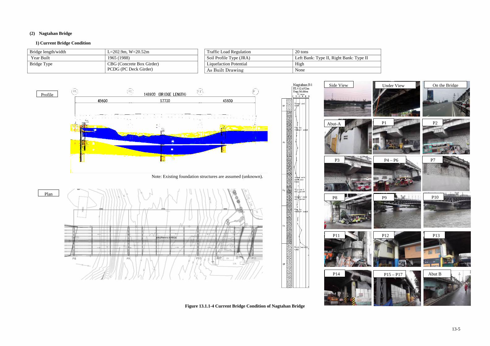
13-5
(2) Nagtahan Bridge
1) Current Bridge Condition
Bridge length/width L=202.9m, W=20.52m Traffic Load Regulation 20 tons Year Built 1965 (1988) Soil Profile Type (JRA) Left Bank: Type II, Right Bank: Type II Bridge Type CBG (Concrete Box Girder)
PCDG (PC Deck Girder) Liquefaction Potential High
As Built Drawing None
Figure 13.1.1-4 Current Bridge Condition of Nagtahan Bridge
P2
P4 – P6
P1 Abut-A
Under View On the Bridge
P3
Side View
P7
P8 P9 P10
P11 P12 P13
P14 P15 – P17 Abut B
Profile
Plan
Note: Existing foundation structures are assumed (unknown).

13-6
2) Bridge Condition
Seismic Vulnerability Items Results of Surveys Analyses/Comments
Earthquake Resisting System
1. Difference in soil types between adjacent piers
Soil Type is consistent along with the entire bridge
- No soil type difference between adjacent piers
2. Continuous or Simply Supported Bridge
Main Spans: Continuous bridge.
- Continuous structure is advantageous against large earthquakes.
3. Eccentric Loads (longitudinal and transverse dir.)
Maximum span ratio: (1st span length): (4th span length) =1.0:1.3
- The span ratio is between 1.0 and 1.5. - Possibility of eccentric loads in both directions
4. Pier Type (single column/wall or multiple columns)
Wide wall type - Single column/wall type is less advantageous than multiple column type against earthquakes in terms of structural redundancy.
5. Height of Abutment (Embankment)
Height of Embankments - Abutment A: 3m - Abutment B: 3m
- Height of embankments is below 5m. - Lower risk of abutments’ collapse under
earthquake
6. Built Year 1966 (Constructed before 1992) - Possibility of confinement loss of pier
columns/walls - Lack of seismic capacities of all the members
Unseating/ Fall-down Prevention System
7. Unseating/Fall-down Prevention Devices (both longitudinal and transverse dir.)
- Longitudinal dir.: Restrainers at Pier-8 & 11; insufficiently installed
- Transverse dir.: Shear keys
- Possibility of unseating due to insufficient seismic restrainers for the longitudinal direction
8. Bearing
1. Steel bearing (Movable or Fixed )
2. Roller type (Fixed)
1. Steel bearing at abutments - Condition: Not functional without bolts
2. Steel bearing (Fixed) at piers - Condition: Anchor bolt is missing.
3. Repaired steel bearing (Fixed) at piers - Condition: Inappropriately repaired
- Possibility of unseating at all the piers due to
corroded bearings - Overall vulnerability: Serious
3. Repaired steel bearing (Fixed)
9. Seat Length
Pier 8 &11: 100cm Minimum Required Seat Length - JRA: 92cm , AASHTO: 52cm
- The seat lengths of piers satisfy JRA’s minimum required seat length.
Foundation
10. Foundation Type (known or unknown)
No available drawings - Unknown structure
11. Scouring Potential of deep scouring at Pier-9 & 10 - Stability reduction of Pier-9 & 10 under
earthquake due to the scouring
12. Soil Type Soil type (JRA): II - Moderate ground condition
13. Liquefaction Potential
- Liquefiable layer type: Sand - N-Value range of the layer: 4-17 Ave. 13
- High liquefaction potential
Seismic Hazard
14. Distance from Active Faults
- Distance: 7.5km - Active Fault Name: Marikina Valley
Fault
- The distance is between 5.0km and 10km. - Moderate effect of the active fault movement
Structural Soundness
Items Results of Surveys Analyses/Comments
Sup
erst
ruct
ures
1. Primary Members
Steel Truss
- Paint deterioration on entire steel truss members
- Overall damage degree: Moderate
2. Secondary Members
Steel Truss
- Paint deterioration on entire steel truss members
- Overall damage degree: Moderate
3. Deck Slab
1. Cracking 2. Water leaking
- Cracking at the bottom of the deck slab through the entire bridge
(Crack width range: 0.1-0.2mm) - Water leaking at the joint of two deck
slabs - Overall damage degree: Moderate
Sub
stru
ctur
es 4. Deterioration
of Columns/ Walls
Secton loss & rebar exposure.
- Section loss & rebar exposure at pier columns due to deterioration
- Overall damage degree: Moderate
Summary of Structural Deficiencies
1. Seismic Vulnerability - Vulnerability of pier columns/walls to large scale earthquakes (confinement loss, deterioration) - Vulnerability of foundations to large scale earthquakes (liquefaction potential, unknown structure,
deep scouring) - High possibility of unseating (insufficient seismic restrainers, corroded bearings)
2. Structural Soundness (Superstructures) - Cracks at the bottom of deck slab through the entire bridge - Water leaking at the joint of deck slabs
3. Structural Soundness (Substructures) - Section loss & rebar exposure at pier columns
Profile
Plan

13-7
3) Traffic Conditions
a) Traffic Volume
Daily and hourly traffic volume is shown in Figure 13.1.1-5, Figure 13.1.1-6 and Table 13.1.1-3.
Table 13.1.1-3 Daily Traffic Volume
Unit: Veh/Day
Motorcycle / Tricycle
Car / Taxi / Pick-up /
Van Jeepney Large Bus
2-Axle Truck
3-Axle Truck
Truck trailer
Sub-Total Total
Day 1 23,150 63,932 1,748 350 4,252 1,979 1,859 74,120 97,270
Day 2 19,114 64,988 1,561 337 5,734 2,084 1,787 76,491 95,605
AADT 21,132 64,460 1,655 344 4,993 2,032 1,823 75,306 96,438
* Sub-total: Not including Motorcycles and Tricycles
b) Level-of-Service (hereafter called as LOS)
LOS is based on the traffic assumptions which are peak hour, road type, free flow speed and number of lanes.
Table 13.1.1-4 Assumption and LOS
LOS: F
Peak Hour Traffic Volume 6,566 Veh/hour
Road Type Urban Road
Free Flow Speed (km/h) 60 km/h
No. of Lanes 6 lanes
* Highway Capacity Manual, 2010
c) Traffic Condition
Analyses of the observed traffic volume condition and LOS are as follows: This bridge connects Sampaloc and Pandacan (North and South of Manila City). Figure 13.1.1-6 shows the
hourly traffic volume by direction, for direction 1 , the observed peak time is in the evening from 5 PM to 6 PM, for direction 2, the observed peak time is in the morning from 7 AM to 8 AM.
No. of lanes is 6 lanes, AADT is 96,438 veh/day, traffic congestion occurred on this bridge both in the morning and in the evening.
Public transport ratio is 2.7%. Truck ratio is 11.7%.Trucks and trailers are utilising this bridge to go to Manila port (north and south port). And, the reason that large trucks and trailers cannot pass to Roxas Blvd, they must pass to Quirino Ave.
Peak hour traffic volume is 6,566 veh/hour, LOS is F because of peak hour traffic volume is very high.
4) Socio-Environmental Assessment Conditions
: Residential Area : Industrial Area
* Analysis by AADT traffic volume * VCR: Volume/Capacity Ratio
Figure 13.1.1-5 Location of Nagtahan Bridge
*Day 1 hourly traffic volume Figure 13.1.1-6 Hourly Traffic Volume
Households and Structures (Area facing the Bridge and the approach road)
- There are many informal settlers including various shops alongside the Bridge. - Fire disaster occurred on 13th July 2012, after the accident some of informal settlers moved to other places, but
19 families with 89 PAPs still remain under the Bridge.
Land use (Area facing the Bridge and the approach road)
- Surrounding area of the Bridge is used for residential, business and industrial purposes. People on north side live a high quality life with large-size TV and PC. On south side along the river are well-maintained sidewalk and community facility such as basketball court.
- Some area under the viaduct on the south side is used for army facilities and car parking. South-west area of the Bridge is closed as a restricted Malacañan Area.
Existing Environmental Condition (Noise, Vibration, Air Pollution and Water contamination.)
- Environmental condition is bad brought about by pollution of traffic flow such as noise, vibration and air pollution.
Environmental Protection Area (national park, reserves and designated wet land)
- The Bridge is not located in cultural property or natural reserve area.
Existence on Location Map of Valuable Ecological Habitats, Historical and Cultural Assets
- South-west area of the Bridge is designated as Malacañan Area.
Malacañan Area (off limit)
Fire disaster had occurred.
Well-equipped condition
such as basketball court and
sidewalk.
There are houses of good
quality alongside the
Bridge.
0
1,000
2,000
3,000
4,000
5,000
6,000
7,000
8,000
6:00
-7:0
0
7:00
-8:0
0
8:00
-9:0
0
9:00
-10:
00
10:0
0-11
:00
11:0
0-12
:00
12:0
0-13
:00
13:0
0-14
:00
14:0
0-15
:00
15:0
0-16
:00
16:0
0-17
:00
17:0
0-18
:00
18:0
0-19
:00
19:0
0-20
:00
20:0
0-21
:00
21:0
0-22
:00
22:0
0-23
:00
23:0
0-24
:00
24:0
0-1:
00
1:00
-2:0
0
2:00
-3:0
0
3:00
-4:0
0
4:00
-5:0
0
5:00
-6:0
0
Time
Tra
ffic
Vol
ume
(Veh
/Day
)
Direction 1
Direction 2
Both
DDDiiirrreeecccttt iiiooonnn 222 DDDiii rrreeecccttt iiiooonnn 111
NNNaaagggtttaaahhhaaannn BBBrrr iiidddgggeee
Truck : 11.7 %
Public Transport : 2.7 %
Peak Hour

13-8
(3) Lambingan Bridge
1) Current Bridge Condition
Bridge length/width L=98.1m, W=24m Traffic Load Regulation 15 tons Year Built 1979 Soil Profile Type (JRA) Left Bank: Type II, Right Bank: Type II Bridge Type PCDG (PC Deck Girder) with Gerber Hinge Liquefaction Potential High
As Built Drawing None
Figure 13.1.1-7 Current Bridge Condition of Lambingan Bridge
Under View On the Bridge Side View
Abut-A P1 P1
P2 Abut - B P2
Detail of Gerber Hinge Detail of Gerber Hinge
Profile
Plan
Detail of Gerber Hinge
Broken Concrete due to uplift Stolen Vertical Restrainer Collision of Vessel
Note: Existing foundation structures are assumed (unknown).

13-9
2) Bridge Condition (Lambingan Bridge)
Seismic Vulnerability Items Results of Surveys Analyses/Comments
Earthquake Resisting System
1. Difference in soil types between adjacent piers
Soil Type is consistent along with the entire bridge
- No soil type difference between adjacent piers
2. Continuous or Simply Supported Bridge
Center Spans: Simply supported with two gerber hinges
- Possibility of unseating at center spans due to simply supported structures with gerber hinges
3. Eccentric Loads (longitudinal and transverse dir.)
Maximum span ratio: (1st span length): (2nd span length) =1.0:3.3
- The span ratio is over 1.5. - Possibility of uplift at both abutments due to
unbalanced span arrangement. 4. Pier Type (single column/wall or multiple columns)
Wall type - Single column/wall type is less advantageous than multiple column type against earthquakes in terms of structural redundancy.
5. Height of Abutment (Embankment)
Height of Embankments - Abut-A: 5m - Abut-B: 5m
- Height of embankments is below 5m. - Lower risk of abutments’ collapse under
earthquake
6. Built Year 1975 (Constructed before 1992) - Possibility of confinement loss of pier
columns/walls - Lack of seismic capacities of all the members
Unseating/ Fall-down Prevention System
7. Unseating/Fall-down Prevention Devices (both longitudinal and transverse dir.)
- Longitudinal dir.: No restrainer - Transverse dir.: Shear keys (damaged)
- Possibility of unseating due to non-existence of seismic restrainers for the longitudinal direction
- Possibility of unseating due to insufficient seismic restrainers for transverse direction
8. Bearing
1. Rubber Pad 2. Rubber Pad (Moveable) (Gerber Hinge)
3. Rubber Pad
(Fixed )
1. Rubber pad (Movable) at abutments - Condition: Severely deteriorated
2. Rubber pad (Gerber hinge) - Condition: Deteriorated
3. Rubber pad (Fixed) at piers - Condition: Deteriorated
- Possibility of unseating at abutments & gerber hinge supports due to corroded bearings
- Overall vulnerability: Serious
9. Seat Length
1. Abut-A: 85cm Minimum Required Seat Length - JRA: 92cm , AASHTO: 52cm
2. Pier-2: 50cm Minimum Required Seat Length
- JRA: 92cm , AASHTO: 52cm
- The seat lengths of abutments don’t satisfy JRA’s minimum required seat length.
- The seat lengths of piers don’t satisfy AASHTO’s minimum required seat length.
- Possibility of unseating due to the very short seat length
Foundation
10. Foundation Type (known or unknown)
No available drawings - Unknown structure
11. Scouring Moderate scouring at Pier-2 - Stability reduction of Pier-2 under earthquake
due to the scouring
12. Soil Type Soil type (JRA): II - Moderate ground condition
13. Liquefaction Potential
- Liquefiable layer type: Sand - N-Value range of the layer: 6-21, Ave.11
- High liquefaction potential
Seismic Hazard
14. Distance from Active Faults
- Distance: 5.3km - Active Fault Name: Marikina Valley
Fault
- The distance is between 5 and 10km. - Moderate effect of the active fault movement
Structural Soundness
Items Results of Surveys Analyses/Comments
Sup
erst
ruct
ures
1. Primary Members
PC girders with gerber hinges
- Large deflection of PC girders at the center span
- Uplift at the side spans - Major cracking at bottom face of girders
due to collision of vessels - Overall damage degree: Serious
2. Secondary Members
RC Side Block
- Section loss of RC side blocks - Overall damage degree: Moderate
3. Deck Slab
1. Cracking 2. Water leaking
- Cracking at nearly half of the bottom face of deck slab
(Crack width range: over 0.5mm) - Water leaking at around the cracking - Overall damage degree: Moderate
Sub
stru
ctur
es
4. Deterioration of Columns/ Walls
Cracking & Scaling/Spalling.
- Minor cracking & scaling/spalling at piers
- Overall damage degree: Moderate
Summary of Structural Deficiencies
1. Seismic Vulnerability - Vulnerability of pier columns/walls to large scale earthquakes (confinement loss) - Vulnerability of foundations to large scale earthquakes (liquefaction potential, unknown structure,
scouring) - High possibility of unseating (simply supported at gerber hinges, insufficient seismic restrainers,
very short seat length, corroded bearings) 2. Structural Soundness (Superstructures)
- Large deflection of PC girders at the center span - Uplift at the side spans - Section loss of RC side blocks - Major cracking at bottom face of girders - Cracking & water leaking at the bottom face of deck slab
3. Structural Soundness (Substructures) - Minor cracking & scaling/spalling at piers
Profile
Plan

13-10
3) Traffic Conditions
a) Traffic Volume
Daily and hourly traffic volume is shown in Figure 13.1.1-8, Figure 13.1.1-9 and Table 13.1.1-5.
Table 13.1.1-5 Daily Traffic Volume
Unit: Veh/Day
Motorcycle / Tricycle
Car / Taxi / Pick-up /
Van Jeepney Large Bus
2-Axle Truck
3-Axle Truck
Truck trailer
Sub-Total Total
Day 1 9,879 13,217 6,210 35 915 139 57 20,573 30,452
Day 2 8,878 14,034 5,975 27 971 134 39 21,180 30,058
AADT 9,379 13,626 6,093 31 943 137 48 20,877 30,255
* Sub-total: Not including Motorcycle and Tricycle
b) Level-of-Service (hereafter called as LOS)
LOS is based on traffic assumptions which are peak hour, road type, free flow speed and number of lanes.
Table 13.1.1-6 Assumption and LOS
LOS: C
Peak Hour Traffic Volume 2,194 Veh/hour
Road Type Urban Road
Free Flow Speed (km/h) 40 km/h
No. of Lanes 6 lanes
* Highway Capacity Manual, 2010
c) Traffic Condition
Analyses of the observed traffic volume condition and LOS are as follows:
This bridge is at Sta. Ana, Manila City. Figure 13.1.1-9 shows the hourly traffic volume by direction, for direction, the observed peak time is in the evening from 6 PM to 7 PM, for direction 2, the observed peak time is in the morning from 6 PM to 7 PM.
No. of lane is 6 lanes, AADT is 30,255 veh/day, traffic volume is only heavy for Manila City bound , Mandaluyong bound is not so much.
Public transport ratio is 29.3%. Truck ratio is 5.4%, jeepney is too much because of there is jeepney station near this bridge. Large trucks and trailers are low because adjacent road is restricted for trucks and trailers.
Peak hour traffic volume is 2,194 veh/hour, LOS is D because of peak hour traffic volume is low.
4) Socio-Environmental Assessment Conditions
: Residential Area : Industrial Area
* Analysis by AADT traffic volume * VCR: Volume/Capacity Ratio
Figure 13.1.1-8 Location of Lambingan Bridge
*Day 1 hourly traffic volume Figure 13.1.1-9 Hourly Traffic Volume
Household and Structures (Area facing the Bridge and the approach road)
- There are many houses at both sides of the approach road.
- There is one illegal household with 5 members under the bridge.
- There are many illegal settlers beside the Bridge at the south side.
Land use (Area facing the Bridge and the approach road)
- Both sides of the Bridge are used for residential and factory area.
Existing Environmental Condition (Noise, Vibration, Air Pollution and Water contamination.)
- Environmental condition is bad brought about by the pollution of traffic flow such as noise, vibration and air
pollution.
Environmental Protection Area (national park, reserves and designated wet land)
- The Bridge is not located in a cultural property or a natural reserve area.
Existence on Location Map of Valuable Ecological Habitats, Historical and Cultural Assets
- The Bridge is not located in a cultural property or a natural reserve area.
There are many informal
settlers beside the Bridge.
There are houses under the Bridge out of dike wall.
DDDiiirrreeecccttt iiiooonnn 222
DDDiii rrreeecccttt iiiooonnn 111
LLLaaammmbbbiiinnngggaaannn BBBrrr iiidddgggeee
Truck : 5.4 %
Public Transport : 29.3 %
0
1,000
2,000
3,000
4,000
6:00
-7:0
0
7:00
-8:0
0
8:00
-9:0
0
9:00
-10:
00
10:0
0-11
:00
11:0
0-12
:00
12:0
0-13
:00
13:0
0-14
:00
14:0
0-15
:00
15:0
0-16
:00
16:0
0-17
:00
17:0
0-18
:00
18:0
0-19
:00
19:0
0-20
:00
20:0
0-21
:00
21:0
0-22
:00
22:0
0-23
:00
23:0
0-24
:00
24:0
0-1:
00
1:00
-2:0
0
2:00
-3:0
0
3:00
-4:0
0
4:00
-5:0
0
5:00
-6:0
0
Time
Tra
ffic
Vol
ume
(Veh
/Day
)
Direction 1
Direction 2
Both
Peak Hour

13-11
(4) Guadalupe Bridge
1) Current Bridge Condition
Bridge length/width L=144.44m, W=25.4m Traffic Load Regulation 20 tons Year Built 1962 (Old), 1978 (New) Soil Profile Type Left Bank: Type I, Right Bank: Type III Bridge Type Continuous Steel Truss (Old)
PC Deck Girder with Gerber Hinge (New) Liquefaction Potential High As Built Drawing None
Figure 13.1.1-10 Current Bridge Condition of Guadalupe Bridge
Abut-A P1
P2
P1
Abut-B
Seating Length
P2
Seating Length
Under View On the Bridge Side View
Abut-A P2 P1
Abut-B
Under View On the Bridge Side View
Joint of New and Old Piers
View of PC Girder
Damaged Gerber Hinge
Bridge Attached Pipes
Seating Length
Profile
Plan
Note: Existing foundation structures are assumed (unknown).

13-12
2) Bridge Condition (Guadalupe Bridge)
Structural Soundness
Items Results of Surveys Analyses/Comments
Sup
erst
ruct
ures
1. Primary Members
PC Girder Steel Truss
- Major cracking at Gerber hinges area
- Paint deterioration on steel truss members
- Overall damage degree: Serious
2. Secondary Members
Steel Truss Member Expansion Joint
- Paint deterioration on steel truss members
- Abnormal spacing of expansion joint at gerber hinge joint of center span due to the rotation of girders
- Overall damage degree: Moderate
3. Deck Slab
PC Girder Steel Truss
- Cracking at the bottom of deck slab through the entire bridge
(Crack width range: 0.1-0.2mm) - Water leaking at the joint between
deck slabs - Overall damage degree: Moderate
Sub
stru
ctur
es 4. Deterioration
of Columns/ Walls
Cracking, Spalling & Rebar exposure
- Cracking, spalling, & rebar exposure at piers due to collision of vessels
- Overall damage degree: Moderate
Summary of Structural Deficiencies
1. Seismic Vulnerability - Vulnerability of pier columns/walls to large scale earthquakes (confinement loss) - Vulnerability of foundations to large scale earthquakes (liquefaction potential, unknown structure,
deep scouring) - High possibility of unseating (simply supported at gerber hinges, insufficient restrainers, very short seat length, corroded bearings)
2. Structural Soundness (Superstructures) - Strengthen gerber hinge portion and side blocks - Cracks at the bottom of deck slab through the entire bridge - Water leaking at the joint between deck slabs 3. Structural Soundness (Substructures) - Cracking, spalling, & rebar exposure at piers
Seismic Vulnerability Items Results of Surveys Analyses/Comments
Earthquake Resisting System
1. Difference in soil types between adjacent piers
Soil Types - Left bank: Type I - Right bank: Type III
- Soil type difference among Pier-2 & Abut-B (Soil type: I or III)
2. Continuous or Simply Supported Bridge
Steel truss: Continuous bridge. PC girder: Simple supported with gerber
hinges
- Possibility of unseating at center spans due to simply supported structures with gerber hinges
3. Eccentric Loads (longitudinal and transverse dir.)
Maximum span ratio: (1st span length): (2nd span length) =1.0:1.2
- The span ratio is between 1.0 and 1.5. - Possibility of eccentric loads only in both
directions. 4. Pier Type (single column/wall or multiple columns)
Wall type: piers for new bridges are structurally connected to the old piers
- Single column/wall type is less advantageous than multiple column type against earthquakes in terms of structural redundancy.
5. Height of Abutment (Embankment)
Height of Embankments - Abutment A: 8m - Abutment B: 8m
- Height of embankments is betwen5 and 10m. - Lower risk of abutments’ collapse under
earthquake
6. Built Year 1962 for steel truss & 1978 for PC I-girders (Constructed before 1992)
- Possibility of confinement loss of pier columns/walls
- Lack of seismic capacities of all the members
Unseating/ Fall-down Prevention System
7. Unseating/Fall-down Prevention Devices (both longitudinal and transverse dir.)
- Longitudinal dir.: Restrainers at abutments; insufficiently installed
- Transverse dir.: Shear keys
- Possibility of unseating at abutments due to insufficient seismic restrainers for the longitudinal direction
8. Bearing
1. Vertical Restrainer 2. H-beam type (Fixed) (Fixed)
3. Rubber pad (Gerber Hinge)
1. Vertical Restrainer at abutments: no bearings - Condition: Corroded 2. Steel bearing (H-beam type) at piers
- Condition: Corroded 3. Rubber pad bearing at gerber hinges
- Condition: Severely corroded
- Possibility of unseating at abutments & gerber hinges due to corroded bearings
- Overall vulnerability: Serious
9. Seat Length
1. Abut-A: 80cm Minimum Required Seat Length - JRA: 88cm , AASHTO: 52cm
2. Pier-2: 35cm Minimum Required Seat Length
- JRA: 88cm , AASHTO: 52cm
- The seat lengths of abutments don’t satisfy JRA’s minimum required seat length.
- The seat lengths of piers don’t satisfy AASHTO’s minimum required seat length.
- High possibility of unseating due to the very short seat length
Foundation
10. Foundation Type (known or unknown)
No available drawings - Unknown structure
11. Scouring Potential of deep scouring at Pier-1 & 2 - Stability reduction of Pier-1 & 2 under
earthquake due to the scouring
12. Soil Type Soil type (JRA): I and II - Moderate ground condition
13. Liquefaction Potential
- Liquefiable layer type: Sand - N-Value range of the layer: 8-28 Ave. 15
- High liquefaction potential
Seismic Hazard
14. Distance from Active Faults
- Distance: 2.4km - Active Fault Name: Marikina Valley
Fault
- The distance is between 2 and 5km. - Serious effect of the active fault movement
Profile
Plan

13-13
3) Traffic Conditions
a) Traffic Volume
Daily and hourly traffic volume is shown in Figure 13.1.1-11, Figure 13.1.1-12 and Table 13.1.1-7.
Table 13.1.1-7 Daily Traffic Volume
Unit: Veh/Day
Motorcycle / Tricycle
Car / Taxi / Pick-up /
Van Jeepney Large Bus
2-Axle Truck
3-Axle Truck
Truck trailer
Sub-Total Total
Day 1 19,576 171,155 0 12,788 4,282 1,571 915 190,711 210,287
Day 2 19,538 191,000 0 13,669 3,917 1,684 837 211,107 230,645
AADT 19,557 181,078 0 13,229 4,100 1,628 876 200,909 220,466
* Sub-total: Not including Motorcycle and Tricycle
b) Level-of-Service (hereafter called as LOS)
LOS is based on traffic assumptions which are peak hour, road type, free flow speed and number of lanes.
Table 13.1.1-8 Assumption and LOS
LOS: F
Peak Hour Traffic Volume 14,366 Veh/hour
Road Type Urban Road
Free Flow Speed (km/h) 60 km/h
No. of Lanes 10 lanes
* Highway Capacity Manual, 2010
c) Traffic Condition
Analyses of the observed traffic volume condition and LOS are as follows:
This bridge is connected with not only Makati City and Quezon City but SLEX and NLEX also. Figure 13.1.1-12 shows the hourly traffic volume by direction, hourly traffic volume which is from 6 AM to 6PM is continuously heavy throughout the daytime. Therefore, this bridge is chronically occurred.
No. of lane is 10 lanes (of the 4 lane s is bus lane), AADT is 220,466 veh/day, this bridge is one of the most heavy traffic volume occurred road which is EDSA.
Public transport ratio is 6.6%. Truck ratio is 3.3%, trailer is regulated in the daytime, but bus company is operated along EDSA.
Peak hour traffic volume is 14,366 veh/hour, LOS is F because of peak hour traffic volume is very high.
4) Socio-Environment al Assessment Conditions
: Business and Industrial Area
House hold and Structures (Area facing the Bridge and the approach road)
- There are many business facilities along both sides of North approach road.
- There are 12 unit informal settlers with 27 members at both sides of north abutment and under the Bridge
Land use (Area facing the Bridge and the approach road)
- North side of the River is used for side walk with basket court and Monument Park.
- There are parks inside of interchange on the south side.
Existing Environmental Condition (Noise, Vibration, Air Pollution and Water contamination.)
- Environmental condition is bad brought about by the pollution of traffic flow such as noise, vibration and
air pollution.
Environmental Protection Area (national park, reserves and designated wet land)
- The Bridge is not located in a cultural property or a natural reserve area.
Existence on Location Map of Valuable Ecological Habitats, Historical and Cultural Assets
- The Bridge is not located in acultural property or a natural reserve area.
* Analysis by AADT traffic volume * VCR: Volume/Capacity Ratio Figure 13.1.1-11 Location of Guadalupe Bridge
*Day 1 hourly traffic volume Figure 13.1.1-12 Hourly Traffic Volume
There are informal settler s’ houses around the abutment.
0
2,000
4,000
6,000
8,000
10,000
12,000
14,000
16,000
6:00
-7:0
0
7:00
-8:0
0
8:00
-9:0
0
9:00
-10:
00
10:0
0-11
:00
11:0
0-12
:00
12:0
0-13
:00
13:0
0-14
:00
14:0
0-15
:00
15:0
0-16
:00
16:0
0-17
:00
17:0
0-18
:00
18:0
0-19
:00
19:0
0-20
:00
20:0
0-21
:00
21:0
0-22
:00
22:0
0-23
:00
23:0
0-24
:00
24:0
0-1:
00
1:00
-2:0
0
2:00
-3:0
0
3:00
-4:0
0
4:00
-5:0
0
5:00
-6:0
0
TimeT
raff
ic V
olum
e (V
eh/D
ay)
Direction 1
Direction 2
Both
DDDiiirrreeecccttt iiiooonnn 222
DDDiii rrreeecccttt iiiooonnn 111
GGGuuuaaadddaaallluuupppeee BBBrrr iiidddgggeee
Truck : 3.3 %
Public Transport : 6.6 %
Continuous throughout the daytime (6AM to 6PM)

13-14
(5) Marikina Bridge
1) Current Bridge Condition
Bridge length/width L=138.2m, W=20.3m Traffic Load Regulation 20 tons Year Built 1980 Soil Profile Type Left Bank: Type I, Right Bank: Type II Bridge Type PCDG (PC Deck Girder) Liquefaction Potential High
As Built Drawing None
Figure 13.1.1-13 Current Bridge Condition of Marikina Bridge
Under View On the Bridge Side View
Abut-A P2 P1
P3
Abut - B P4
Cracks on Pier
Attached Pipes
Seating Length
No Bearing Pad
Cracks on Abutment Cracks on Deck Slab
Profile
Plan
Note: Existing foundation structures are assumed (unknown).

13-15
2) Bridge Condition (Marikina Bridge)
Structural Soundness
Items Results of Surveys Analyses/Comments
Sup
erst
ruct
ures
1. Primary Members
PC girder bridge
- PC girders apparently in good condition.
- Overall damage degree: Good
2. Secondary Members
RC Cross Beam Expansion Joint
- Deterioration at cross beams - Water leaking at expansion joins - Overall damage degree: Moderate
3. Deck Slab
1. Cracking 2. Water leaking
- Major cracking at the bottom face and surface of deck slab through the entire bridge.
- Water leaking from the wide cracking at the deck slab
- Overall damage degree: Serious
Sub
stru
ctur
es 4. Deterioration
of Columns/ Walls
Retrofitted columns
- Pier columns are already retrofitted and in good condition.
- Overall damage degree: Good
Summary of Structural Deficiencies
1. Seismic Vulnerability - Vulnerability of foundations to large scale earthquakes (liquefaction potential, unknown structure,
scouring) - High possibility of unseating (simply supported, no seismic restrainers, short seat length, deformed bearings, and non-existence of bearings)
2. Structural Soundness (Superstructures) - Deterioration at cross beams - Water leaking at expansion points - Major cracking & water leaking at the bottom face of deck slab through the entire bridge - Water leaking from expansion joints
3. Structural Soundness (Substructures) - None
Seismic Vulnerability Items Results of Surveys Analyses/Comments
Earthquake Resisting System
1. Difference in soil types between adjacent piers
Soil Type is consistent along with the entire bridge
- No soil type difference between adjacent piers
2. Continuous or Simply Supported Bridge
Simply supported
- All spans are simply supported. - High possibility of unseating due to simply
supported structures
3. Eccentric Loads (longitudinal and transverse dir.)
Maximum span ratio: (1st span length): (2nd span length) =1.0:1.3
- The span ratio is less than 1.5 - Possibility of eccentric loads is low in the
transverse direction.
4. Pier Type (single column/wall or multiple columns)
Multiple-column type - Multiple column type is more advantageous than single column/wall type against earthquakes in terms of structural redundancy.
5. Height of Abutment (Embankment)
Height of Embankments - Abut-A: 2.5m - Abut-B: 2.5m Note: Pile bent abutment
- Lower risk of abutments’ collapse under earthquake
6. Built Year 1980 (Constructed before 1992) - Possibility of confinement loss of pier
columns/walls
Unseating/ Fall-down Prevention System
7. Unseating/Fall-down Prevention Devices (both longitudinal and transverse dir.)
- Longitudinal dir.: No restrainer - Transverse dir.: No restrainer
- High possibility of unseating under earthquake due to non-existence of seismic restrainers
8. Bearing
1. Rubber pad 2. No bearing at with angle steel piers
(Fixed or Movable)
1. Rubber pad with angle steel at abutments - Condition: Severely deformed (angle steel)
2. No bearing at piers
- Possibility of unseating due to deformed bearings, and non-existence of bearings
- Overall vulnerability: Serious
9. Seat Length
1. Abut-A: 65cm Minimum Required Seat Length - JRA: 85cm , AASHTO: 48cm
- The seat lengths of abutments don’t satisfy JRA’s minimum required seat length.
- Possibility of unseating due to the short seat length
Foundation 10. Foundation Type (known or unknown)
No available drawings - Unknown structure
11. Scouring Scouring at Pier-2 & 3 - Stability reduction of Pier-2 & 3 due to the
scouring under earthquake
12. Soil Type Soil type (JRA): II - Moderate ground condition
13. Liquefaction Potential
- Liquefiable layer type: Sand - N-Value range of the layer: 7-34 Ave. 19
- Very high liquefaction potential
Seismic Hazard
14. Distance from Active Faults
- Distance: 1.0km - Active Fault Name: Marikina Valley
Fault
- The distance is less than 2.0km. - Serious effect of the active fault movement
Profile
Plan

13-16
3) Traffic Conditions
a) Traffic Volume
Daily and hourly traffic volume is shown in Figure 13.1.1-14, Figure 13.1.1-15 and Table 13.1.1-9.
Table 13.1.1-9 Daily Traffic Volume
Unit: Veh/Day
Motorcycle / Tricycle
Car / Taxi / Pick-up /
Van Jeepney Large Bus
2-Axle Truck
3-Axle Truck
Truck trailer
Sub-Total Total
Day 1 16,413 29,112 8,940 85 1,453 42 12 39,644 56,057
Day 2 18,429 30,323 8,357 104 1,412 87 18 40,301 58,730
AADT 17,421 29,718 8,649 95 1,433 65 15 39,973 57,394
* Sub-total: Not including Motorcycle and Tricycle
b) Level-of-Service (hereafter called as LOS)
LOS is based on traffic assumptions which are peak hour, road type, free flow speed and number of lanes.
Table 13.1.1-10 Assumption and LOS
LOS: F
Peak Hour Traffic Volume 3,629 Veh/hour
Road Type Urban Road
Free Flow Speed (km/h) 60 km/h
No. of Lanes 4 lanes
* Highway Capacity Manual, 2010
c) Traffic Condition
Analyses of the observed traffic volume condition and LOS are as follows.
This bridge connects Antipolo City and Quezon City, it crosses the Marikina River. Figure 13.1.1-15 shows the hourly traffic volume by direction, for direction 1, the observed peak time is in the morning from 6 AM to 7 AM, for direction 2, the observed peak time is in the morning from 6 PM to 7 PM.
No. of lane is 4 lanes, AADT is 57,394 veh/day, traffic volume is only towards Antipolo City and Manila Area.
Public transport ratio is 21.9%. Truck ratio is 3.8%, jeepney is too much because of Antipolo City is a big residential area. Large trucks and trailers are low.
Peak hour traffic volume is 3,629 veh/hour, LOS is F because of peak hour traffic volume is high with few no. of lanes.
4) Socio-Environment al Assessment Conditions
: Residential Area : Industrial Area
* Analysis by AADT traffic volume * VCR: Volume/Capacity Ratio
Figure 13.1.1-14 Location of Marikina Bridge
*Day 1 hourly traffic volume Figure 13.1.1-15 Hourly Traffic Volume
Households and Structures (Area facing the Bridge and the approach road)
- There is no house, shop or factory around the Bridge along the approach road.
- There is no any illegal structure on both sides under the Bridge.
Land use (Area facing the Bridge and the approach road)
- There are many houses, shops and factories along the approach roads.
- Both sides of the river banks are used for recreation area and side walk.
Existing Environmental Condition (Noise, Vibration, Air Pollution and Water contamination.)
- Environmental condition is relatively good except for the pollution of traffic flow such as noise, vibration
and air pollution along the road.
Environmental Protection Area (national park, reserves and designated wet land)
- The Bridge is not located in a cultural property or a natural reserve area.
Existence on Location Map of Valuable Ecological Habitats, Historical and Cultural Assets
- The Bridge is not located in a cultural property or a natural reserve area.
Restaurant
Side walk
DDDiiirrreeecccttt iiiooonnn 222
DDDiii rrreeecccttt iiiooonnn 111
MMMaaarrr iiikkkiiinnnaaa BBBrrr iiidddgggeee
Truck : 3.8 % Public Transport : 21.9 % VCR* : 1.60
0
1,000
2,000
3,000
4,000
5,000
6,000
6:00
-7:0
0
7:00
-8:0
0
8:00
-9:0
0
9:00
-10:
00
10:0
0-11
:00
11:0
0-12
:00
12:0
0-13
:00
13:0
0-14
:00
14:0
0-15
:00
15:0
0-16
:00
16:0
0-17
:00
17:0
0-18
:00
18:0
0-19
:00
19:0
0-20
:00
20:0
0-21
:00
21:0
0-22
:00
22:0
0-23
:00
23:0
0-24
:00
24:0
0-1:
00
1:00
-2:0
0
2:00
-3:0
0
3:00
-4:0
0
4:00
-5:0
0
5:00
-6:0
0
Time
Tra
ffic
Vol
ume
(Veh
/Day
)
Direction 1
Direction 2
BothPeak Hour

13-17
13.1.2 Comparison of Improvement Measures
1) Delpan Bridge
Improvement Measure Scheme Detail of Improvement Measures & Evaluation
Alt
ern
ativ
e 1
- S
eism
ic R
etro
fit
and
Rep
air
Des
crip
tion
/ D
esig
n
Con
cept
Seismic capacity improvement of pier walls (wall retrofit) Seismic capacity improvement of foundations (pile for reinforcement & soil
improvement) Improvement of unseating/fall-down prevention system (unseating prevention
cables/chains, seat extender, replacement of bearings) Improvement of the deck slab soundness (repair) Improvement of the PC girders’ soundness
Con
stru
ctio
n
Method/ Technology
Concrete jacketing (wall retrofit) Steel pipe sheet pile foundation (pile for reinforcement) Chemical grouting with SPSP wall (soil improvement) Unseating prevention system
Difficulty Traffic control during abutment retrofit works Pile-driving under the existing superstructure
Cost
Seismic Retrofit Works
Wall retrofit Pile for reinforcement Soil improvement Unseating prevention system
0.53
Repair Works
Epoxy injection & mortar repair Floor slab water proof sheet Replacement of expansion joint 0.01
Others Working platform on the water Temporary detour bridge 0.01
Total 0.55
Pot
enti
al
Imp
act
to
Env
iron
men
t
River occupation during the works for piers in water
Requirement of large construction yard
Temporary detour bridge installation during abutment retrofit works
Requirement of temporary resettlement for the construction
EVALUATION: Recommended
Alt
erna
tive
2 -
Rep
lace
men
t
Des
crip
tion
/ D
esig
n
Con
cept
Application of existing bridge planning condition in order to confirm the cost
effectiveness of seismic retrofit & repair works
Application of PC girder bridge for advantage of less maintenance even near coastal
areas
Application of steel pipe sheet pile foundation to piers in water: no need for sheet
pile installation
Con
stru
ctio
n
Method/ Technology
Continuous PC Box-girder bridge
Steel pipe sheet pile foundation (for piers)
Cast-in-place pile foundation (for abutments)
Difficulty Requirement of long term construction period for cast-in-place PC
box girders
Cost
Superstructure Continuous PC box-girder bridge 0.40
Substructure Wall type 0.07
Foundation Steel pipe sheet pile foundation
Cast-in-place pile foundation 0.43
Others Working platform on the water
Temporary detour bridge 0.10
Total 1.00
Pot
enti
al
Imp
act
to
Env
iron
men
t
River occupation during the works for piers in water
Long construction period for cast-in-place PC girders
Temporary detour bridge installation during the whole construction
Requirement of temporary resettlement for the construction
EVALUATION: Not Recommended
Unseating prevention cableConcrete jacketing
Chemical grouting
Replacement of expansion joints
- Epoxy injection & mortar repair - Floor slab waterproof sheet
Steel pipe sheet pile foundation (No need for sheet pile installation)
Unseating prevention system- Unseating prevention cables/chains- Seat extender - Replacement of bearings
Steel pipe sheet pile wall (SPSP wall) (Protection against liquefaction)
- Unseating prevention chains - Seat extender - Replacement of bearings
Continuous PC box-girder bridge
Cast-in-place pile foundation Steel pipe sheet pile foundation(No need for sheet pile installation)
Comparison of Improvement Measures for Delpan Bridge

13-18
2) Nagtahan Bridge
Comparison of Improvement Measures for Nagtahan Bridge
Improvement Measure Scheme Detail of Improvement Measures & Evaluation
Alt
ern
ativ
e 1
- S
eism
ic R
etro
fit
and
Rep
air
Des
crip
tion
/ D
esig
n C
once
pt
Seismic capacity improvement of pier wall (wall retrofit) Seismic capacity improvement of foundations (pile for reinforcement) Improvement of unseating/fall-down prevention system (unseating
prevention chains, replacement of bearings) Improvement of the deck slab soundness (repair) Improvement of the steel members’ soundness
Con
stru
ctio
n
Method/ Technology
Concrete jacketing (wall retrofit) Steel pipe sheet pile foundation (pile for reinforcement) Unseating prevention system
Difficulty Traffic control in improvement of abutments. Pile-driving under the existing superstructure
Cost
Seismic Retrofit Works
Wall retrofit Pile for reinforcement Unseating prevention system Replacement of bearings
0.46
Repair Works
Epoxy injection & mortar repair Floor slab water proof sheet Replacement of expansion joints Repaint of steel truss members
0.03
Others Working platform on the water Temporary detour bridge
0.01
Total 0.50
Pot
enti
al
Imp
act
to
En
viro
nm
ent Requirement of low-impact construction for Malacañan area
River occupation during the works for piers in water Temporary detour bridge installation during abutment retrofit works Requirement of temporary resettlement for the construction: many informal
settlers under approach bridges
EVALUATION: Recommended
Alt
ern
ativ
e 2
- R
epla
cem
ent
Des
crip
tion
/ D
esig
n C
once
pt
Application of existing bridge planning condition in order to confirm the cost effectiveness of seismic retrofit & repair works
Application of light weight & low height superstructure type in order to maintain the adequate vertical clearance
Application of steel pipe sheet pile foundation to piers in water: no need for sheet pile installation
Con
stru
ctio
n
Method/ Technology
- Continuous steel box-girder bridge - Steel pipe sheet pile foundation - Cast-in-place pile foundation
Difficulty None: Typical erection methods are applicable
Cost
Superstructure Continuous steel box-girder bridge 0.38 Substructure Wall type 0.07
Foundation Steel pipe sheet pile foundation Cast-in-place pile foundation
0.45
Others Working platform on the water Temporary detour bridge Approach road
0.10
Total 1.00
Pot
enti
al
Imp
act
to
En
viro
nm
ent
Requirement of low-impact construction to Malacañan area River occupation during the works for piers in water Temporary detour bridge installation during the whole construction Requirement of temporary resettlement for the construction: many informal
settlers under approach bridges
EVALUATION: Not Recommended
Continuous steel-box-girder bridge
Cast-in-place pile foundation
Steel pipe sheet pile foundation(No need for sheet pile installation)
Steel pipe pile foundation
Concrete Jacketing
Replacement of expansion joints
- Repaint of steel members - Epoxy injection & mortar repair - Floor slab waterproof sheet
Replacement of bearings
Steel pipe sheet pile foundation (No need for sheet pile installation)
Unseating prevention system- Unseating prevention chains - Replacement of bearings
- Unseating prevention chains - Replacement of bearings
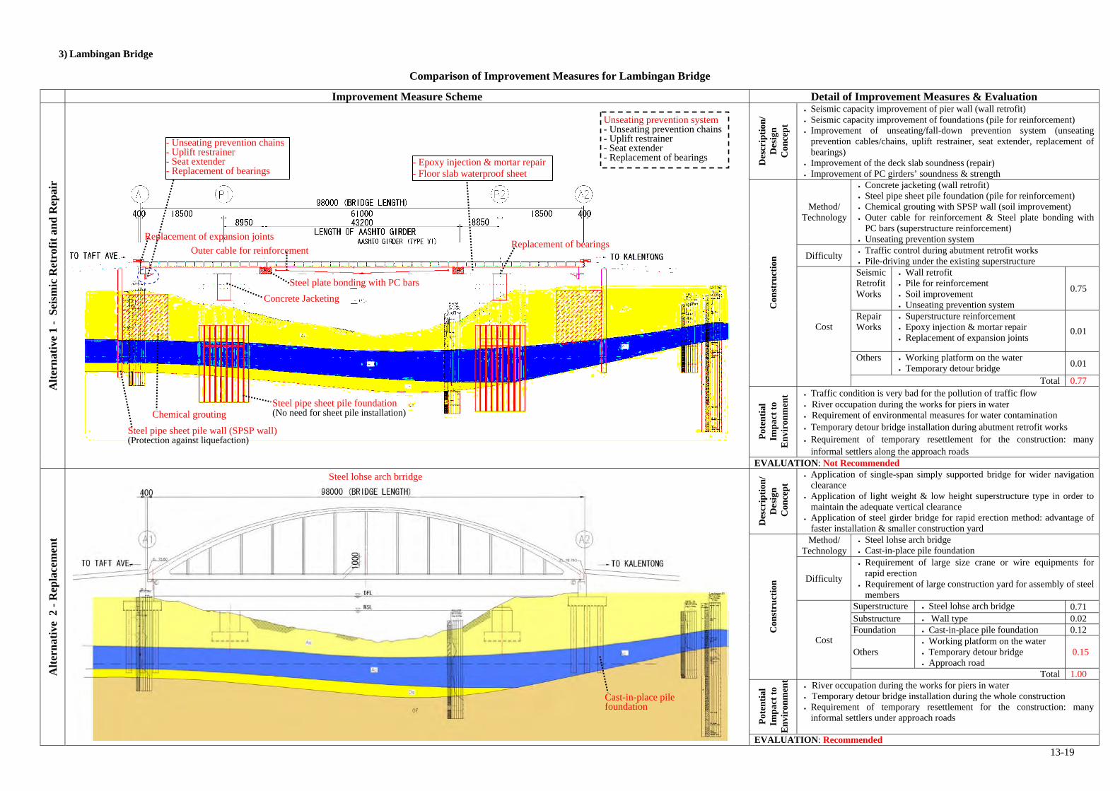
13-19
3) Lambingan Bridge
Comparison of Improvement Measures for Lambingan Bridge
Improvement Measure Scheme Detail of Improvement Measures & Evaluation
Alt
ern
ativ
e 1
- S
eism
ic R
etro
fit
and
Rep
air
Des
crip
tion
/ D
esig
n
Con
cep
t
Seismic capacity improvement of pier wall (wall retrofit) Seismic capacity improvement of foundations (pile for reinforcement) Improvement of unseating/fall-down prevention system (unseating
prevention cables/chains, uplift restrainer, seat extender, replacement of bearings)
Improvement of the deck slab soundness (repair) Improvement of PC girders’ soundness & strength
Con
stru
ctio
n
Method/ Technology
Concrete jacketing (wall retrofit) Steel pipe sheet pile foundation (pile for reinforcement) Chemical grouting with SPSP wall (soil improvement) Outer cable for reinforcement & Steel plate bonding with
PC bars (superstructure reinforcement) Unseating prevention system
Difficulty Traffic control during abutment retrofit works Pile-driving under the existing superstructure
Cost
Seismic Retrofit Works
Wall retrofit Pile for reinforcement Soil improvement Unseating prevention system
0.75
Repair Works
Superstructure reinforcement Epoxy injection & mortar repair Replacement of expansion joints
0.01
Others Working platform on the water Temporary detour bridge 0.01
Total 0.77
Pot
enti
al
Imp
act
to
En
viro
nm
ent Traffic condition is very bad for the pollution of traffic flow
River occupation during the works for piers in water Requirement of environmental measures for water contamination Temporary detour bridge installation during abutment retrofit works Requirement of temporary resettlement for the construction: many
informal settlers along the approach roads EVALUATION: Not Recommended
Alt
ern
ativ
e 2
- R
epla
cem
ent
Des
crip
tion
/ D
esig
n C
once
pt
Application of single-span simply supported bridge for wider navigation clearance
Application of light weight & low height superstructure type in order to maintain the adequate vertical clearance
Application of steel girder bridge for rapid erection method: advantage of faster installation & smaller construction yard
Con
stru
ctio
n
Method/ Technology
Steel lohse arch bridge Cast-in-place pile foundation
Difficulty
Requirement of large size crane or wire equipments for rapid erection
Requirement of large construction yard for assembly of steel members
Cost
Superstructure Steel lohse arch bridge 0.71 Substructure Wall type 0.02 Foundation Cast-in-place pile foundation 0.12
Others Working platform on the water Temporary detour bridge Approach road
0.15
Total 1.00
Pot
enti
al
Imp
act
to
En
viro
nm
ent
River occupation during the works for piers in water Temporary detour bridge installation during the whole construction Requirement of temporary resettlement for the construction: many
informal settlers under approach roads
EVALUATION: Recommended
Cast-in-place pile foundation
Steel lohse arch brridge
Chemical grouting
Outer cable for reinforcement
Steel plate bonding with PC bars
Concrete Jacketing
- Epoxy injection & mortar repair- Floor slab waterproof sheet
- Unseating prevention chains - Uplift restrainer - Seat extender - Replacement of bearings
Replacement of bearings
Steel pipe sheet pile wall (SPSP wall) (Protection against liquefaction)
Replacement of expansion joints
Steel pipe sheet pile foundation (No need for sheet pile installation)
Unseating prevention system- Unseating prevention chains- Uplift restrainer - Seat extender - Replacement of bearings

13-20
4) Guadalupe Bridge
Comparison of Improvement Measures for Guadalupe Bridge
Improvement Measure Scheme Detail of Improvement Measures & Evaluation
Alt
ern
ativ
e 1
- S
eism
ic R
etro
fit
and
Rep
air
Des
crip
tion
/ D
esig
n
Con
cep
t
Seismic capacity improvement of pier wall (wall retrofit) Seismic capacity improvement of foundations (pile for reinforcement &
soil improvement) Improvement of unseating/fall-down prevention system (unseating
prevention cables/chains, replacement of bearings) Improvement of the deck slab soundness (repair) Improvement of PC girders’ soundness & strength
Con
stru
ctio
n
Method/ Technology
Concrete jacketing (wall retrofit) Steel pipe sheet pile foundation (pile for reinforcement) Chemical grouting with SPSP wall (soil improvement) Unseating prevention system
Difficulty Traffic control during abutment retrofit works Pile-driving under the existing superstructure
Cost
Seismic Retrofit Works
Wall retrofit Pile for reinforcement Soil improvement Unseating prevention system
0.53
Repair Works
Steel plate bonding with PC bars Epoxy injection & mortar repair Replacement of expansion joint
0.02
Others Working platform on the water Temporary detour bridge
0.09
Total 0.64
Pot
enti
al
Imp
act
to
En
viro
nm
ent
River occupation during the works for piers in water Temporary detour bridge installation during abutment retrofit works Requirement of temporary resettlement for the construction: many
informal settlers around the bridges EVALUATION: Not Recommended
Alt
ern
ativ
e 2
- R
epla
cem
ent
Des
crip
tion
/ D
esig
n C
once
pt
Application of span ratio of center-lane bridges Application of light weight & low height superstructure type in order to
maintain the adequate vertical clearance Application of steel girder bridge for rapid erection method: advantage of
faster installation & smaller construction yard Application of steel pipe sheet pile foundation to piers in water: no need
for sheet pile installation
Con
stru
ctio
n
Method/ Technology
Continuous steel plate deck box-girder bridge Steel pipe sheet pile foundation (for piers in water) Cast-in-place pile foundation (for piers on land)
Difficulty
Requirement of large size crane or wire equipments for rapid erection
Requirement of large construction yard for assembly of steel members
Installation of temporary detour bridge: limited space
Cost
Superstructure Continuous steel plate deck box-
girder bridge 0.34
Substructure Wall type 0.08
Foundation Steel pipe sheet pile foundation Cast-in-place pile foundation
0.48
Others Working platform on the water Temporary detour bridge Approach road
0.10
Total 1.00
Pot
enti
al
Imp
act
to
En
viro
nm
en River occupation during the works for piers in water Temporary detour bridge installation during the whole construction Requirement of temporary resettlement for the construction: many
informal settlers around the bridges: Large impact to business area
EVALUATION: Recommended
Cast-in-place pile foundation
Steel pipe sheet pile foundation (No need for sheet pile installation)
Note: Target of replacement is only both side-lane bridges
Continuous steel plate deck box-girder bridge
Out cable for deflection
Steel Plate Bonding
Chemical Grouting
Concrete Jacketing
- Epoxy injection & mortar repair - Floor slab waterproof sheet
Replacement of bearings
Steel pipe sheet pile wall (SPSP wall) (Protection against liquefaction)
Replacement of expansion joints
Steel pipe sheet pile foundation (No need for sheet pile installation)
Unseating prevention system - Unseating prevention chains - Seat extender - Replacement of bearings
- Unseating prevention chains - Seat extender - Replacement of bearings

13-21
5) Marikina Bridge
Comparison of Improvement Measures for Marikina Bridge
Improvement Measure Scheme Detail of Improvement Measures & Evaluation
Alt
ern
ativ
e 1
- S
eism
ic R
etro
fit
and
Rep
air
Des
crip
tion
/ D
esig
n
Con
cep
t
Seismic capacity improvement of pier columns (column retrofit) Seismic capacity improvement of foundations (pile for reinforcement &
soil improvement) Improvement of unseating/fall-down prevention system (seat extender,
unseating prevention chains/cables, shear keys, replacement/ installation of bearings)
Improvement of the deck slab soundness (repair) Improvement of PC girders’ soundness & strength
Con
stru
ctio
n
Method/ Technology
Steel pipe sheet pile foundation & steel pipe pile foundation (pile for reinforcement)
Chemical grouting & SPSP wall (soil improvement) Unseating prevention system
Difficulty Traffic control during abutment retrofit works Pile-driving under the existing superstructure
Cost
Seismic Retrofit Works
Column retrofit Pile for reinforcement Soil improvement Unseating prevention system
0.66
Repair Works
Epoxy injection & mortar repair Replacement of expansion joints
0.02
Others Working platform on the water Temporary detour bridge 0.01
Total 0.69
Pot
enti
al
Imp
act
to
En
viro
nm
ent
River occupation during the works for piers in water Temporary detour bridge installation during abutment retrofit works
EVALUATION: Not Recommended
Alt
ern
ativ
e 2
- R
epla
cem
ent
Des
crip
tion
/ D
esig
n
Con
cep
t
Application of existing bridge planning condition in order to confirm the cost effectiveness of seismic retrofit & repair works
Application of PC girder bridge for advantage of less maintenance even near coastal areas
Application of steel pipe sheet pile foundation to piers in water: no need for sheet pile installation
Con
stru
ctio
n
Method/ Technology
Continuous PC I-girder bridge Steel pipe sheet pile foundation Method (in river) Cast-in-place pile foundation Method (on land)
Difficulty Typical erection method applicable using track cranes
Cost
Super- structure
Continuous PC I-girder bridge
0.21
Substructure Wall type 0.08
Foundation Steel pipe sheet pile foundation Cast-in-place pile foundation
0.61
Others Working platform on the water Temporary detour bridge
0.10
Total 1.00
Pot
enti
al
Imp
act
to
En
viro
nm
ent
River occupation during the works for piers in water Temporary detour bridge installation during the whole construction Long construction period for cast-in-place PC girders
EVALUATION: Recommended
Continuous PC I-girder bridge
Cast-in-place pile foundation
Steel pipe sheet pile foundation(No need for sheet pile installation)
Chemical grouting
Replacement of expansion joints
Steel pipe sheet pile wall (SPSP wall) (Protection against liquefaction)
- Epoxy injection & mortar repair- Floor slab waterproof sheet
Steel pipe pile foundation Steel pipe sheet pile foundation(No need for sheet pile installation)
Unseating prevention system- Unseating prevention chains/cables - Seat extender - Shear keys - Replacement/installation of bearings
- Unseating prevention chains - Seat extender - Shear keys - Replacement of bearings
- Unseating prevention cables- Seat extender - Shear keys - Installation of bearings

13-22
13.2 Evaluation of the Second Screening for Package C
This section summarizes 2nd screening result of Package C (selection of objective bridges outside Metro Manila
for outline design). The evaluation results are explained with the following two steps, as well as Package B.
1) Evaluation of current bridge & bridge site conditions
Bridge condition, traffic condition, and socio-environmental condition are summarized for 7 objective
bridges, based on the inspection results obtained in this project.
2) Comparative study on improvement measure schemes (replacement or seismic retrofit)
Comparative study on two alternative improvement measure schemes (replacement or seismic retrofit) is
conducted for the objective 7 bridges. As a result of the study, either replacement or seismic retrofit is
recommended for each bridge. The selection of the improvement measure schemes is done in accordance
with the following rule which is conventionally applied in the Philippines.
- Recommendation of replacement: if cost of seismic retrofit plan including repair works is over or equal
to 60 % of that of replacement plan, replacement is recommendable.
- Recommendation of seismic retrofit: other than the above case, seismic retrofit cost is recommendable.
13.2.1 Results of the Second Screening

13-23
(1) Buntun Bridge
1) Structural and Geological Outline
Bridge length/width L=1102m, W=9.1m Traffic Load Regulation 18 ton Year Built 1967 Soil Profile Type II (JRA) Bridge Type - Main Spans: Simply-supported steel truss bridge
- Approach Spans: Simply-supported steel I-girder bridge Liquefaction Potential Very High (layer: As) As-built drawing None
Figure 13.2.1-1 Structural and Geological Outline of Buntun Bridge
Wall type
Profile
P7 – P15P6 P16
P5
P4
P1 P2 P3Abut-A
Seat Length (P4)
Plan
Wall type Rigid frame type Rigid frame type with shear wall
River Pond
Simply-supported steel I-girder bridge
Simply-supported steel I-girder bridge Simply-supported steel truss bridge
1102m
(2 lanes)
Abut-B
Side view
Under the bridge
On the bridge
Water leaking
Overhanging deck slab
Deformed
Deformed
Scouring
Short
Short
Liquefiable layer (As)
Note: Existing foundation structures are assumed (unknown).

13-24
2) Bridge Condition
Seismic Vulnerability Items Results of Surveys Analyses/Comments
Earthquake Resisting System
1. Difference in soil types between adjacent piers
Soil Type is consistent along with the entire bridge
- No soil type difference between adjacent piers
2. Continuous or Simply Supported Bridge
1. Main Spans: Simply supported 2. Approach Spans: Simply supported
- All spans are simply supported. - High possibility of unseating due to simply
supported structures 3. Eccentric Loads (longitudinal and transverse dir.)
Maximum span ratio: (2nd span length): (3rd span length) = 1.0:1.7
- The span ratio is over 1.5 - Possibility of eccentric loads only in the
transverse direction: simply supported
4. Pier Type (single column/wall or multiple columns)
1. Wall type 2. Rigid frame type 3. Rigid frame type with shear walls
- 13 out of 16 piers are rigid frame type - Multiple column type is more advantageous
than single column/wall type against earthquakes in terms of structural redundancy.
5. Height of Abutment (Embankment)
Height of Embankments - Abut-A: 3m - Abut-B: 3m
- Heights of embankments are below 5m. - Lower risk of abutments’ collapse under
earthquake
6. Built Year 1967 (Constructed before 1992) - Possibility of confinement loss of pier
columns/walls - Lack of seismic capacities of all the members
Unseating/ Fall-down Prevention System
7. Unseating/Fall-down Prevention Devices (both longitudinal and transverse dir.)
- Longitudinal dir.: No restrainer - Transverse dir.: No restrainer
- High possibility of unseating due to non-existence of seismic restrainers
8. Bearing
1. Linear type 2. Roller type (Movable or Fixed ) (Movable hinge)
3. Pin type (Fixed hinge)
1. Steel bearings (linear type) at abutments - Condition: Deformed (longitudinal dir.)
2. Steel bearings (roller type) at piers - Condition: Good
3. Steel bearings (pin type) at piers - Condition: Good except for Pier-11
bearing: Pin portion is lost. - Types of existing bearing are not vulnerable to
earthquakes - Possibility of unseating at Pier-11 due to
damaged bearings - Overall vulnerability: Serious
9. Seat Length
1. Abut-A: 48cm Minimum Required Seat Length - JRA: 85cm, AASHTO: 43cm
2. Pier-2: 55cm (steel I-girder side) Minimum Required Seat Length - JRA: 95cm, AASHTO: 53cm
- The seat lengths of abutments and piers don’t satisfy JRA’s minimum required seat length.
- Possibility of unseating due to the short seat length
Foundation
10. Foundation Type (known or unknown)
No available drawings - Unknown structure
11. Scouring Moderate scouring at Pier-5 - Stability reduction of Pier-5 under earthquake
due to the scouring 12. Soil Type Soil type (JRA): I - Firm ground condition
13. Liquefaction Potential
- Liquefiable layer type: Sand - N-Value range of the layer: 6 – 9
- Very high liquefaction potential
Seismic Hazard
14. Distance from Active Faults
- Distance: 15.9km - Active Fault Name: Taboan River Fault
- The distance is over 10km. - Small effect of the active fault movement
Structural Soundness
Items Results of Surveys Analyses/Comments
Sup
erst
ruct
ures
1. Primary Members
Steel Truss
- All superstructure members were recently repainted and they are in good condition.
- Overall damage degree: Good
2. Secondary Members
Steel Truss
- All superstructure members were recently repainted and they are in good condition.
- Overall damage degree: Good
3. Deck Slab
- Minor cracking at the bottom face of deck slab through the entire bridge
(Crack width range: 0.1-0.2mm) - Water leaking at the overhanging deck
slabs - Overall damage degree: Moderate
Sub
stru
ctur
es
4. Deterioration of Columns/ Walls
Minor Cracking
- Minor cracks on some pier columns - Overall damage degree: Small
Summary of Structural Deficiencies
1. Seismic Vulnerability - Vulnerability of pier columns/walls to large scale earthquakes (confinement loss) - Vulnerability of foundations to large scale earthquakes (liquefaction potential, unknown structure,
scouring) - High possibility of unseating (simply supported, no seismic restrainers, short seat length, damaged bearings)
2. Structural Soundness (Superstructures) - Cracks at the bottom face of deck slab through the entire bridge - Water leaking at the overhanging deck slabs
3. Structural Soundness (Substructures) - None: Only minor cracks on some pier columns
Missing
Location: Pier-11
Cracking Water leaking

13-25
3) Traffic Condition
a) Traffic Volume
Daily and hourly traffic volumes are shown in Figure 13.2.1-2., Figure 13.2.1-3 and Table 13.2.1-1. Analyses of
the observed traffic condition are shown in “3) Traffic Condition”.
Table 13.2.1-1 Daily Traffic Volume
Unit: Veh/Day
Motorcycle / Tricycle
Car / Taxi / Pick-up /
Van Jeepney Large Bus
2-Axle Truck
3-Axle Truck
Truck trailer
Sub-Total Total
Day 1 10,794 4,463 1,325 79 776 155 81 6,879 17,673
Day 2 11,109 13,969 1,154 601 785 148 232 16,889 29,153
AADT 9,908 4,357 1,573 59 676 115 83 6,862 16,770
* Sub-total: Not including Motorcycle and Tricycle
b) Level-of-Service (hereafter called as LOS)
LOS is assumed, based on the following traffic conditions namely; peak hour, road type, free flow speed and
number of lanes.
Table 13.2.1-2 Assumption and LOS
LOS: C
Peak Hour Traffic Volume 1,650 Veh/hour
Road Type Rural Road
Free Flow Speed (km/h) 30 km/h
No. of Lanes 2 lanes
* Highway Capacity Manual, 2010
c) Traffic Condition
Analyses of the observed traffic volume condition and LOS are as follows.
Buntun bridge connects Tugegarao City proper to Cagayan and Apayao Provinces. Figure 13.2.1-3 shows the hourly traffic volume by direction, for direction 1, the observed peak time is in the evening from 5 PM to 6 PM as both direction peak hour, for direction 2, the observed peak time is in the morning from 6 AM to 7 PM.
Public transport ratio is 23.8% of daily traffic volume which is 16,770 veh/day without motorcycle, is high volume.
Buntun bridge is used as a commuter road. LOS is C because of peak hour traffic volume is high and no passing lane.
4) Socio-Environmental Assessment Conditions
Household and Structures (Area facing the Bridge and the approach road)
- There are several houses surrounding the Bridge and along the approach road.
- (East side of under the Bridge) Slope of abutment bank is very steep, there is no structure.
- At the second pier of trussed girder there is a temporary house used for watching field during daytime.
Land use (Area facing the Bridge and the approach road)
- Dry riverbed of west side is used for agriculture such as rice crop.
- Some areae under the Bridge on dry riverbed are used for stock yard of farmers.
- There are some houses but not facing directly to the road in the West side of the approach.
- There are some vendors facing the road in the East side of the approach.
Existing Environmental Condition (Noise, Vibration, Air Pollution and Water contamination.)
- Environmental condition is good except for the pollution of traffic flow such as noise, vibration and air
pollution.
Environmental Protection Area (national park, reserves and designated wet land)
- The Bridge is not located in a cultural property or a natural reserve area.
Existence on Location Map of Valuable Ecological Habitats, Historical and Cultural Assets
- The Bridge is not located in a cultural property or a natural reserve area.
* Analysis by AADT traffic volume * VCR: Volume/Capacity Ratio
Figure 13.2.1-2 Location of Buntun Bridge
*Day 1 hourly traffic volume Figure 13.2.1-3 Hourly Traffic Volume
0
500
1,000
1,500
2,000
2,500
3,000
6:00
-7:0
0
7:00
-8:0
0
8:00
-9:0
0
9:00
-10:
00
10:0
0-11
:00
11:0
0-12
:00
12:0
0-13
:00
13:0
0-14
:00
14:0
0-15
:00
15:0
0-16
:00
16:0
0-17
:00
17:0
0-18
:00
18:0
0-19
:00
19:0
0-20
:00
20:0
0-21
:00
21:0
0-22
:00
TimeT
raff
ic V
olum
e (V
eh/D
ay)
Direction 1
Direction 2
Both
DDDiiirrreeecccttt iiiooonnn 222
DDDiii rrreeecccttt iiiooonnn 111
BBBuuunnntttuuunnn BBBrrr iiidddgggeee
Truck : 12.7 % Public Transport : 23.8 % VCR* : 0.44
Peak Hour
Thereare several houses and restaurant along the road.
A house under the Bridge
Rice field Used for stock yard of farmers

13-26
(2) 1st Mandaue-Mactan Bridge
1) Structural and Geological Outline
Bridge length/width L=859m, W=9.1m Traffic Load Regulation None Year Built 1972 Soil Profile Type I & II (JRA) Bridge Type - Main Spans: Continuous steel truss bridge
- Approach Spans: Continuous steel I-girder bridge Note: Partially simply supported (side spans)
Liquefaction Potential Very high (layer: As) As-built drawing None
Figure 13.2.1-4 Structural and Geological of 1st Mandaue Mactan Bridge
Profile
Plan
River
P12 – P13
P12 P13
P6
P9
P9
P8
P1 – P5
P5
P7 – P8
P7 P8
Collided by aship (repaired)
P11
P10
P10 – P11
Seat Length (P13)
Collided by a ship (repaired)
Bottom of pier caps (P7)
Rebar exposure
859m
Only fixed bearings in the main spans
(2 lanes)
Abut-A
Abut-B
Side view
Under the bridge On the bridge P6 P7
Liquefiable layer (As)
Short
Deck slab
Water leaking
3-span-continuous steel I-girder bridge
Simply-supported composite steel I-girder bridge
Simply-supported composite steel I-girder bridge
3-span-continuous steel I-girder bridge
3-span-continuous steel truss bridge
Collided by a ship (repaired)
F F M
M M M F MM M F F
M MM F M M
MF
M F
Only one fixed condition in the continuous bridge
Only one fixed condition in the continuous bridge
Only one fixed condition in the continuous bridge
Liquefiable layer (As)
Note: Existing foundation structures are assumed (unknown).
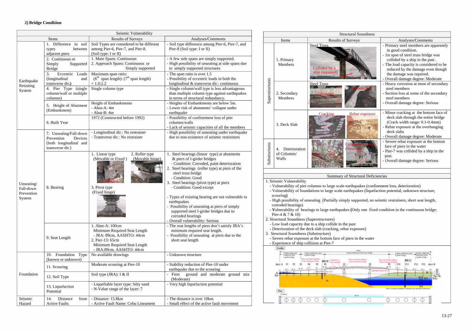
13-27
2) Bridge Condition
Seismic Vulnerability Items Results of Surveys Analyses/Comments
Earthquake Resisting System
1. Difference in soil types between adjacent piers
Soil Types are considered to be different among Pier-6, Pier-7, and Pier-8. (Soil type: I or II)
- Soil type difference among Pier-6, Pier-7, and Pier-8 (Soil type: I or II)
2. Continuous or Simply Supported Bridge
1. Main Spans: Continuous 2. Approach Spans: Continuous or Simply supported
- A few side spans are simply supported. - High possibility of unseating at side spans due
to simply supported structures 3. Eccentric Loads (longitudinal and transverse dir.)
Maximum span ratio: (6th span length): (7th span length) = 1.0:2.2
- The span ratio is over 1.5 - Possibility of eccentric loads in both the
longitudinal & transverse dir.: continuous 4. Pier Type (single column/wall or multiple columns)
Single column type - Single column/wall type is less advantageous than multiple column type against earthquakes in terms of structural redundancy.
5. Height of Abutment (Embankment)
Height of Embankments - Abut-A: 4m - Abut-B: 4m
- Heights of Embankments are below 5m. - Lower risk of abutments’ collapse under
earthquake
6. Built Year 1972 (Constructed before 1992) - Possibility of confinement loss of pier
columns/walls - Lack of seismic capacities of all the members
Unseating/ Fall-down Prevention System
7. Unseating/Fall-down Prevention Devices (both longitudinal and transverse dir.)
- Longitudinal dir.: No restrainer - Transverse dir.: No restrainer
- High possibility of unseating under earthquake due to non-existence of seismic restrainers
8. Bearing
1. Linear type 2. Roller type (Movable or Fixed ) (Movable hinge)
3. Pivot type (Fixed hinge)
1. Steel bearings (linear type) at abutments & piers of I-girder bridges - Condition: Corroded, paint deterioration
2. Steel bearings (roller type) at piers of the steel truss bridge
- Condition: Good 3. Steel bearings (pivot type) at piers
- Condition: Good except - Types of existing bearing are not vulnerable to
earthquakes - Possibility of unseating at piers of simply
supported steel I-girder bridges due to corroded bearings
- Overall vulnerability: Serious
9. Seat Length
1. Abut-A: 100cm Minimum Required Seat Length - JRA: 89cm, AASHTO: 44cm
2. Pier-13: 65cm Minimum Required Seat Length - JRA:89cm, AASHTO: 44cm
- The seat lengths of piers don’t satisfy JRA’s minimum required seat length.
- Possibility of unseating at piers due to the short seat length
Foundation
10. Foundation Type (known or unknown)
No available drawings - Unknown structure
11. Scouring Moderate scouring at Pier-10 - Stability reduction of Pier-10 under
earthquake due to the scouring
12. Soil Type Soil type (JRA): I & II - Firm ground and moderate ground mix
(Moderate)
13. Liquefaction Potential
- Liquefiable layer type: Silty sand - N-Value range of the layer: 7
- Very high liquefaction potential
Seismic Hazard
14. Distance from Active Faults
- Distance: 15.8km - Active Fault Name: Cebu Lineament
- The distance is over 10km. - Small effect of the active fault movement
Structural Soundness
Items Results of Surveys Analyses/Comments
Sup
erst
ruct
ures
1. Primary Members
Steel Truss
- Primary steel members are apparently in good condition.
- 1st span of steel truss bridge was collided by a ship in the past .
- The load capacity is considered to be reduced by the damage even though the damage was repaired.
- Overall damage degree: Moderate
2. Secondary Members
Steel Truss
- Heavy corrosion at most of secondary steel members
- Section loss at some of the secondary steel members
- Overall damage degree: Serious
3. Deck Slab
- Minor cracking at the bottom face of deck slab through the entire bridge
(Crack width range: 0.1-0.4mm) - Rebar exposure at the overhanging
deck slabs - Overall damage degree: Moderate
Sub
stru
ctur
es
4. Deterioration of Columns/ Walls
- Severe rebar exposure at the bottom face of piers in the water
- Pier-7 was collided by a ship in the past.
- Overall damage degree: Serious
Summary of Structural Deficiencies
1. Seismic Vulnerability - Vulnerability of pier columns to large scale earthquakes (confinement loss, deterioration) - Vulnerability of foundations to large scale earthquakes (liquefaction potential, unknown structure, scouring)
- High possibility of unseating (Partially simply supported, no seismic restrainers, short seat length, corroded bearings)
- Vulnerability of bearings to large earthquakes (Only one fixed condition in the continuous bridge; Pier-4 & 7 & 10)
2. Structural Soundness (Superstructures) - Low load capacity due to a ship collide in the past - Deterioration of the deck slab (cracking, rebar exposure) 3. Structural Soundness (Substructure) - Severe rebar exposure at the bottom face of piers in the water - Experience of ship collision at Pier-7
Corroded
Cracking Rebar exposure
Corroded
Section loss
P7
Rebar exposure
Collided by a ship (repaired)
Collided by a ship (repaired)

13-28
3) Traffic Condition
a) Traffic Volume
Daily and hourly traffic volume is shown in Figure 13.2.1-5, Figure 13.2.1-6 and Table 13.2.1-3
Table 13.2.1-3 Daily Traffic Volume
Unit: Veh/Day
Motorcycle / Tricycle
Car / Taxi / Pick-up /
Van Jeepney Large Bus
2-Axle Truck
3-Axle Truck
Truck trailer
Sub-Total Total
Day 1 27,215 30,073 7,220 8 52 4 0 37,357 64,572
Day 2 29,779 39,072 9,349 15 46 7 2 48,491 78,270
AADT 28,497 34,573 8,285 12 49 6 1 42,924 71,421
* Sub-total: Not including Motorcycle and Tricycle
b) Level-of-Service (hereafter called as LOS)
LOS is assumed, based on the following traffic conditions namely; peak hour, road type, free flow speed and
number of lanes.
Table 13.2.1-4 Assumption and LOS
LOS: F
Peak Hour Traffic Volume 6,741 Veh/hour
Road Type Urban Road
Free Flow Speed (km/h) 40 km/h
No. of Lanes 2 lanes
* Highway Capacity Manual, 2010
c) Traffic Condition
Analyses of the observed traffic volume condition and LOS are as follows:
This bridge connects Mactan Island and Cebu Cityspanning across the Mactan Channel. Figure 13.2.1-6 shows the hourly traffic volume by direction, for both direction 1 and 2, the observed peak time is in the morning from 7 AM to 8 AM.
No. of lane is 2 lanes, AADT is 71,421 veh/day, traffic congestion chronically occurrs on this bridge. Public transport ratio is 19.3%, jeepneys are passing this bridge to go to Mactan Island and Cebu City. And,
truck ratio is 0.1%, because truck entry is regulated on this bridge. However, in the 2nd Mactan Bridge, which is the next bridge large trucks and trailers can pass.
Peak hour traffic volume is 6,741 veh/hour, LOS is F because of peak hour traffic volume is very high and there is no passing lane.
4) Socio-Environmental Assessment Conditions
: Residential Area : Industrial Area
Household and Structures (Area facing the Bridge and the approach road)
- There are many illegal settlers under the Bridge on both sides of the strait.
- Total number of illegal houses is 189 and number of PAPs are 733 at the time of survey.
Land use (Area facing the Bridge and the approach road)
- Under the Bridge is used for residential area including some kinds of shops and illegal settlers.
Existing Environmental Condition (Noise, Vibration, Air Pollution and Water contamination.)
- Environmental condition is not so bad for noise, vibration and air pollution. But sanitary condition such as
waste effluent is bad without water and sewerage.
Environmental Protection Area (national park, reserves and designated wet land)
- The Bridge is not located in a cultural property or a natural reserve area.
Existence on Location Map of Valuable Ecological Habitats, Historical and Cultural Assets
- The Bridge is not located in a cultural property or a natural reserve area.
* Analysis by AADT traffic volume * VCR: Volume/Capacity Ratio Figure 13.2.1-5 Location of 1st Mandaue-Mactan
Bridge
*Day 1 hourly traffic volume Figure 13.2.1-6 Hourly Traffic Volume
Thereare many illegal
settlers under the Bridge.
DDDiiirrreeecccttt iiiooonnn 222 DDDiii rrreeecccttt iiiooonnn 111
111 sss ttt MMMaaaccctttaaannn BBBrrr iiidddgggeee
Truck : 0.1 % Public Transport : 19.3 % VCR* : 1.96
0
1,000
2,000
3,000
4,000
5,000
6,000
7,000
8,000
6:00
-7:0
0
7:00
-8:0
0
8:00
-9:0
0
9:00
-10:
00
10:0
0-11
:00
11:0
0-12
:00
12:0
0-13
:00
13:0
0-14
:00
14:0
0-15
:00
15:0
0-16
:00
16:0
0-17
:00
17:0
0-18
:00
18:0
0-19
:00
19:0
0-20
:00
20:0
0-21
:00
21:0
0-22
:00
22:0
0-23
:00
23:0
0-24
:00
24:0
0-1:
00
1:00
-2:0
0
2:00
-3:0
0
3:00
-4:0
0
4:00
-5:0
0
5:00
-6:0
0
Time
Tra
ffic
Vol
ume
(Veh
/Day
)
Direction 1
Direction 2
Both
Peak Hour

13-29
(3) Palanit Bridge
1) Structural and Geological Outline
Bridge length/width L=123m, W=8.9m Traffic Load Regulation 7 ton Year Built 1972 Soil Profile Type I (JRA) Bridge Type - Main Spans: Simply supported steel truss bridge
- Approach Spans: Simply supported steel I-girder bridge Liquefaction Potential None As-built drawing None
Figure 13.2.1-7 Structural and Geological of Palanit Bridge
Profile
Plan River
Simply-supported steel I-girder bridgeSimply-supported steel truss bridge 123m
P2P1
P1
P2
F M F M M F
Primary member of steel truss
Deck slab Deck slab
Additional cross beam for reinforcement
(2 lanes)
Abut-A
Abut-B Abut-B
Side view Under the bridge On the bridge
Primary member of steel truss
Deteriorated
Section loss
Cracking Honeycomb/Spallin
Short
Short
Short
Note: Existing foundation structures are assumed (unknown).

13-30
2) Bridge Condition
Seismic Vulnerability Items Results of Surveys Analyses/Comments
Earthquake Resisting System
1. Difference in soil types between adjacent piers
Soil Type is consistent along with the entire bridge
- No soil type difference between adjacent piers
2. Continuous or Simply Supported Bridge
1. Main Spans: Simply supported 2. Approach Spans: Simply supported
- All spans are simply supported. - High possibility of unseating due to simply
supported structures 3. Eccentric Loads (longitudinal and transverse dir.)
Maximum span ratio: (1st span length): (2nd span length) = 2.7:1.0
- The span ratio is over 1.5 - Possibility of eccentric loads only in the
transverse direction: simply supported 4. Pier Type (single column/wall or multiple columns)
Wall type - Single column/wall type is less advantageous than multiple column type against earthquakes in terms of structural redundancy.
5. Height of Abutment (Embankment)
Height of Embankments - Abut-A: 3m - Abut-B: 3m
- Heights of embankments are below 5m. - Lower risk of abutments’ collapse under
earthquake
6. Built Year 1972 (Constructed before 1992) - Possibility of confinement loss of pier
columns/walls - Lack of seismic capacities of all the members
Unseating/ Fall-down Prevention System
7. Unseating/Fall-down Prevention Devices (both longitudinal and transverse dir.)
- Longitudinal dir.: No restrainer - Transverse dir.: No restrainer
- High possibility of unseating due to non-existence of seismic restrainers
8. Bearing
1. Linear type 2. Roller type (Movable or Fixed ) (Movable hinge)
3. Pivot type (Fixed hinge)
1. Steel bearings (linear type) at Abut-B, Pier-1 & 2 - Condition: Heavily corroded
2. Steel bearings (roller type) at Pier-1 - Condition: Corroded, paint deterioration
3. Steel bearings (pivot type) at Abut-A - Condition: Good
- Types of existing bearing are not vulnerable to
earthquakes - Possibility of unseating at Abut-B, and
Pier-1 & 2 due to corroded bearings - Overall vulnerability: Serious
9. Seat Length
1. Abut-A: 55cm Minimum Required Seat Length - JRA: 84cm, AASHTO: 41cm
2. Pier-2: 44cm Minimum Required Seat Length - JRA: 104cm, AASHTO: 51cm
- The seat lengths of abutments and piers don’t satisfy JRA’s minimum required seat length. The seat length of Pier-2 doesn’t satisfy even AASHTO’s criteria.
- High possibility of unseating due to the very short seat length
Foundation
10. Foundation Type (known or unknown)
No available drawings - Unknown structure
11. Scouring None
- No scouring effect
12. Soil Type Soil type (JRA): I
- Firm ground condition
13. Liquefaction Potential
- The ground at the site consists of nonliquefiable layers
- No liquefaction potential
Seismic Hazard
14. Distance from Active Faults
- Distance: 7.6km - Active Fault Name: Northern Samar
Lineament
- The distance is between 5 and 10km. - Moderate effect of the active fault movement
Structural Soundness
Items Results of Surveys Analyses/Comments
Sup
erst
ruct
ures
1. Primary Members
Steel Truss
- Severe painting deterioration and corrosion on steel members - Section loss at some part of
primary steel members - Low load capacity (load limit: 7t) - Overall damage degree: Serious
2. Secondary Members
Steel Truss
- Severe painting deterioration and corrosion on steel members - Overall damage degree: Serious
3. Deck Slab
- Major cracking & water leaking at the bottom face of deck slab through the entire bridge
(Crack width range: 0.3-0.7mm) - Honeycomb/Spalling at the bottom face of
deck slab in Span-2 & 3
- Overall damage degree: Serious
Sub
- st
ruct
ures
4. Deterioration of Columns/ Walls
- Rebar exposure & cracking at the bearing base of Pier-1
- Overall damage degree: Moderate
Summary of Structural Deficiencies
1. Seismic Vulnerability - Vulnerability of pier columns/walls to large scale earthquakes (confinement loss, deterioration) - Vulnerability of foundations to large scale earthquakes (unknown structure) - High possibility of unseating (simply supported, no seismic restrainers, short seat length, corroded bearings)
2. Structural Soundness (Superstructures) - Low load capacity (load limit: 7t) - Deterioration & Section loss at steel truss members - Severe deterioration of the deck slab (cracking, honeycomb/spalling, and water leaking)
3. Structural Soundness (Substructures) - Rebar exposure & cracking at the bearing base of Pier-1
Location: Pier-11
Corroded
Corroded Corroded
Cracking & water leaking
Honeycomb/ Spalling
Section loss
Deteriorated
Cracking

13-31
3) Traffic Conditions
a) Traffic Volume
Daily and hourly traffic volume is shown in Figure 13.2.1-8, Figure 13.2.1-9 and Table 13.2.1-5.
Table 13.2.1-5 Daily Traffic Volume
Unit: Veh/Day
Motorcycle / Tricycle
Car / Taxi / Pick-up /
Van Jeepney Large Bus
2-Axle Truck
3-Axle Truck
Truck trailer
Sub-Total Total
Day 1 562 184 64 70 90 42 10 460 1,022
Day 2 632 154 69 87 99 67 6 482 1,224
AADT 730 199 65 93 93 76 10 536 1,265
* Sub-total: Not including Motorcycle and Tricycle
b) Level-of-Service (hereafter called as LOS)
LOS is based on traffic assumptions which are peak hour, road type, free flow speed and number of lanes.
Table 13.2.1-6 Assumption and LOS
LOS: B
Peak Hour Traffic Volume 149 Veh/hour
Road Type Local Road
Free Flow Speed (km/h) 30 km/h
No. of Lanes 2 lanes
* Highway Capacity Manual, 2010
c) Traffic Condition
Analyses of the observed traffic volume condition and LOS are as follows: This is the only bridge is which connects Calbayog City and Allen City in Samar Island. Figure 13.2.1-9
shows the hourly traffic volume by direction, for both direction 1 and 2, the observed peak time is in the morning from 6 AM to 7 AM.
No. of lane is 2 lanes, AADT is 1,265 veh/day, traffic volume is too small, thus vehicle capacity ratio is 0.04. If this bridge will be destroyed as a result of large earthquake, the passing vehicles will have to drive long
distance detour through the center island. Peak hour traffic volume is 149 veh/hour, LOS is B because of peak hour traffic volume is very small.
4) Socio-Environmental Assessment Conditions
: Residential Area : House
Household and Structures (Area facing the Bridge and the approach road)
- There are2 houses immediately beside the Bridge. The number of PAPs under the Bridge is 12.
- Water pipeline is held by the Bridge.
Land use (Area facing the Bridge and the approach road)
- The area is generally agricultural with coconut farming and fishing as primary source of livelihood.
- Under the Bridge is used for shed of fishing boat, breeding place for fighting cock, and for drying area.
Existing Environmental Condition (Noise, Vibration, Air Pollution and Water contamination.)
- Environmental condition is good except for the pollution of traffic flow such as noise, vibration and air pollution.
- Based on the water quality sampling analysis, some of the residents dispose their waste through the river but the
level of contamination is under the standard.
Environmental Protection Area (national park, reserves and designated wet land)
- The Bridge is not located in a cultural property or a natural reserve area.
Existence on Location Map of Valuable Ecological Habitats, Historical and Cultural Assets
- The Bridge is not located in a cultural property or a natural reserve area.
* Analysis by AADT traffic volume * VCR: Volume/Capacity Ratio
Figure 13.2.1-8 Location of Palanit Bridge
*Day 1 hourly traffic volume Figure 13.2.1-9 Hourly Traffic Volume
There are informal settler houses.
Under the Bridge is used for
boat shed and drying area.
Water pipeline. 0
100
200
300
6:00
-7:0
0
7:00
-8:0
0
8:00
-9:0
0
9:00
-10:
00
10:0
0-11
:00
11:0
0-12
:00
12:0
0-13
:00
13:0
0-14
:00
14:0
0-15
:00
15:0
0-16
:00
16:0
0-17
:00
17:0
0-18
:00
18:0
0-19
:00
19:0
0-20
:00
20:0
0-21
:00
21:0
0-22
:00
Time
Tra
ffic
Vol
ume
(Veh
/Day
)
Direction 1
Direction 2
Both
DDDiiirrreeecccttt iiiooonnn 222 DDDiii rrreeecccttt iiiooonnn 111
PPPaaalllaaannniii ttt BBBrrr iiidddgggeee
Truck : 33.4 % Public Transport : 29.4 % VCR* : 0.04
Peak Hour

13-32
River (2 lanes)
Simply-supported steel langer arch bridge
259m Profile
Plan
P1
P1
Abut-A
Abut-B
Abut-B
Primary steel members
Deck slab Overhanging deck slab
Large deflection under large live loads Abut-A
Side view
Under the bridge On the bridge
Primary steel members
Corroded
Corroded
Honeycomb
Rebar exposure
Short seat length
Short
Short
Note: Existing foundation structures are assumed (unknown).
Liquefiable layer (As)
(4) Mawo Bridge
1) Structural and Geological Outline
Bridge length/width L=259m, W=8.8m Traffic Load Regulation 7t Year Built 1976 Soil Profile Type I & III (JRA) Bridge Type Simply supported steel langer arch bridge Liquefaction Potential Very high (layer: As)
As-built drawing None
Figure 13.2.1-10 Structural and Geological Outline of Mawo Bridge

13-33
2) Bridge Condition
Seismic Vulnerability Items Results of Surveys Analyses/Comments
Earthquake Resisting System
1. Difference in soil types between adjacent piers
Soil Types are considered to be different between Pier-1 and Abut-B. (Soil type: I or III)
- Soil type difference between Pier-1 and Abut-B (Soil type: I or III)
2. Continuous or Simply Supported Bridge
Simply supported - All spans are simply supported. - High possibility of unseating due to simply
supported structures 3. Eccentric Loads (longitudinal and transverse dir.)
Maximum span ratio: (1st span length): (2nd span length) =1.0:1.0
- The span ratio is 1.0. - Little possibility of eccentric loads
4. Pier Type (single column/wall or multiple columns)
Wall type - Single column/wall type is less advantageous than multiple column type against earthquakes in terms of structural redundancy.
5. Height of Abutment (Embankment)
Height of Embankments - Abut-A: 2m - Abut-B: 2m
- Heights of embankments are below 5m. - Lower risk of abutments’ collapse under
earthquake
6. Built Year 1976 (Constructed before 1992) - Possibility of confinement loss of pier
columns/walls - Lack of seismic capacities of all the members
Unseating/ Fall-down Prevention System
7. Unseating/Fall-down Prevention Devices (both longitudinal and transverse dir.)
- Longitudinal dir.: No restrainer - Transverse dir.: No restrainer
- High possibility of unseating due to non-existence of seismic restrainers
8. Bearing
1. Pivot type 2. Roller type (Fixed hinge) (Movable hinge)
1. Steel bearings (pivot type) at Abut-A, and Pier-1
- Condition: Corroded, paint deterioration 2. Steel bearings (roller type) at Abut-B,
and Pier-1 - Condition: Corroded, paint deterioration
- Types of existing bearing are not vulnerable to
earthquakes - Possibility of unseating at abutments,
and Pier-1 due to corroded bearings - Overall vulnerability: Moderate
9. Seat Length
1. Abut-B: 90cm Minimum Required Seat Length - JRA: 135cm, AASHTO: 66cm
2. Pier-2: 90cm Minimum Required Seat Length - JRA: 135cm, AASHTO: 66cm
- The seat lengths of abutments and Pier-1 don’t satisfy JRA’s minimum required
- Possibility of unseating due to the short seat length
Foundation
10. Foundation Type (known or unknown)
No available drawings - Unknown structure
11. Scouring Condition of Pier-1 is unknown.
- Unknown
12. Soil Type Soil type (JRA): I & III
- Firm ground and soft ground mix (Soft)
13. Liquefaction Potential
- Liquefiable layer type: Sand - N-Value range of the layer: 8-12
- Very high liquefaction potential
Seismic Hazard
14. Distance from Active Faults
- Distance: 1.4km - Active Fault Name: Northern Samar
Lineament
- The distance is less than 2km. - Fatal effect of the active fault movement
Structural Soundness
Items Results of Surveys Analyses/Comments
Sup
erst
ruct
ures
1. Primary Members
Steel langer arch
- Painting deterioration and corrosion on steel members - Low load capacity (load limit: 7t) - Overall damage degree: Moderate
2. Secondary Members
Steel langer arch
- Painting deterioration and corrosion on steel members
- Overall damage degree: Moderate
3. Deck Slab
- Cracking & water leaking at the bottom face of deck slab through the entire bridge (Crack width range: 0.3-0.7mm)
- Honeycomb/Spalling at the bottom face of deck slab in Span-1 & 2
- Rebar exposure at the overhanging deck slab
- Overall damage degree: Serious
Sub
- st
ruct
ures
4. Deterioration of Columns/ Walls
- Pier-1 is apparently in good condition.
- Overall damage degree: Good
Summary of Structural Deficiencies
1. Seismic Vulnerability - Vulnerability of pier columns/walls to large scale earthquakes (confinement loss) - Vulnerability of foundations to large scale earthquakes (liquefaction potential, unknown structure) - High possibility of unseating (simply supported, no seismic restrainers, short seat length, corroded bearings)
2. Structural Soundness (Superstructures) - Low load capacity (load limit: 7t), abnormal vibration of the superstructure - Large deflection under large live loads - Deterioration at steel truss members - Severe deterioration of the deck slab (cracking, honeycomb/spalling, water leaking, rebar exposure)
3. Structural Soundness (Substructures) - None
Corroded Corroded
Corroded
Corroded Corroded
Cracking & water leaking
Rebar exposure Honeycomb/Spalling

13-34
3) Traffic Conditions
a) Traffic Volume
Daily and hourly traffic volume is shown in Figure 13.2.1-11, Figure 13.2.1-12 and Table 13.2.1-7.
Table 13.2.1-7 Daily Traffic Volume
Unit: Veh/Day
Motorcycle / Tricycle
Car / Taxi / Pick-up /
Van Jeepney Large Bus
2-Axle Truck
3-Axle Truck
Truck trailer
Sub-Total Total
Day 1 2,193 275 75 70 130 71 12 633 2,826
Day 2 2,534 270 75 87 135 83 11 661 3,526
AADT 2,889 322 73 93 130 102 14 735 3,625
* Sub-total: Not including Motorcycle and Tricycle
b) Level-of-Service (hereafter called as LOS)
LOS is based on traffic assumptions which are peak hour, road type, free flow speed and number of lanes.
Table 13.2.1-8 Assumption and LOS
LOS: B
Peak Hour Traffic Volume 432 Veh/hour
Road Type Urban Road
Free Flow Speed (km/h) 30 km/h
No. of Lanes 2 lanes
* Highway Capacity Manual, 2010
c) Traffic Condition
Analyses of the observed traffic volume condition and LOS are as follows:
This bridge is the only bridge that connects Calbayog City and Allen City in Samar Island. Figure 13.2.1-12 shows the hourly traffic volume by direction, for both direction 1 and 2 , the observed peak time is in the morning from 7 AM to 8 AM.
No. of lane is 2 lanes, AADT is 3,625 veh/day, traffic volume is too small, thus vehicle capacity ratio is 0.06. If this bridge will be destroyed as result of large earthquake, passing vehicles will drive a long distance
detour through the center island. Peak hour traffic volume is 432 veh/hour. LOS is B because the peak hour traffic volume is very small.
4) Socio-Environmental Assessment Conditions
: Residential Area
Household and Structures (Area facing the Bridge and the approach road)
- There are many houses immediately beside the Bridge.
- There are 7 informal settlers under the Bridge with 37 PAPs.
Land use (Area facing the Bridge and the approach road)
- North side area and along approach road on south side are used for residential area.
- Under the Bridge is used for shed of boat, breeding place for domestic animal such as fighting cock, pig and for
drying area of washed clothes.
Existing Environmental Condition (Noise, Vibration, Air Pollution and Water contamination.)
- Environmental condition is good except for the pollution of traffic flow such as noise, vibration and air pollution.
- Based on the water quality sampling analysis, some of the residents dispose their waste through the river but the
level of contamination is under the standard.
Environmental Protection Area (national park, reserves and designated wet land)
- The Bridge is not located in a cultural property or a natural reserve area.
Existence on Location Map of Valuable Ecological Habitats, Historical and Cultural Assets
- The Bridge is not located in a cultural property or a natural reserve area.
* Analysis by AADT traffic volume * VCR: Volume/Capacity Ratio
Figure 13.2.1-11 Location of Mawo Bridge
*Day 1 hourly traffic volume Figure 13.2.1-12 Hourly Traffic Volume
There are houses immediately
beside the Bridge.
Used for storage, breeding area
and etc.
There are houses beside
the Bridge
DDDiiirrreeecccttt iiiooonnn 222
DDDiii rrreeecccttt iiiooonnn 111
MMMaaawwwooo BBBrrr iiidddgggeee
Truck : 33.6 % Public Transport : 22.6 % VCR* : 0.06
0
100
200
300
400
500
6:00
-7:0
0
7:00
-8:0
0
8:00
-9:0
0
9:00
-10:
00
10:0
0-11
:00
11:0
0-12
:00
12:0
0-13
:00
13:0
0-14
:00
14:0
0-15
:00
15:0
0-16
:00
16:0
0-17
:00
17:0
0-18
:00
18:0
0-19
:00
19:0
0-20
:00
20:0
0-21
:00
21:0
0-22
:00
Time
Tra
ffic
Vol
ume
(Veh
/Day
)
Direction 1
Direction 2
Both
Peak Hour

13-35
(5) Biliran Bridge
1) Structural and Geological Outline
Bridge length/width L=252m, W=8.9m Traffic Load Regulation 15t Year Built 1976 Soil Profile Type I (JRA) Bridge Type - Main Spans: Simply supported steel langer arch bridge
- Approach Spans: Simply supported steel I-girder bridge Liquefaction Potential None As-built drawing None
Figure 13.2.1-13 Structural and Geological Outline of Biliran Bridge
Profile
Sea Water (2 lanes)
Plan
P2 P3
P4
P5 Seat Length (P2) Abnormal vibration
Abut-A
Abut-B Abut-B
252m Simply-supported steel I-girder bridge Simply-supported steel
I-girder bridge Simply-supported steel langer arch bridge
Total replaced (in 1990s)
Settlement (P3)
Replaced
Side view
Under the bridge On the bridge
P1
Short
Short
Overhanging deck slab
Water leaking
Replaced
Joint-less deck slab
Unseating prevention cables
Note: Existing foundation structures are assumed (unknown,. except for Pier-3 & 4)

13-36
2) Bridge Condition
Structural Soundness
Items Results of Surveys Analyses/Comments
Sup
erst
ruct
ures
1. Primary Members
Steel I-girder
- Corrosion on steel I-girder members
- Primary members of steel langer arch are in good condition.
- Overall damage degree: Moderate
2. Secondary Members
Steel langer arch
- Secondary members are in good condition
- Overall damage degree: Good
3. Deck Slab
- The bottom face of deck slab is repaired with carbon fiber sheet.
- Spalling & water leaking at the overhanging deck slab
- Overall damage degree: Moderate
Sub
- st
ruct
ures
4. Deterioration of Columns/ Walls
- Cracking at piers - Overall damage degree: Moderate
Summary of Structural Deficiencies
1. Seismic Vulnerability - Vulnerability of pier columns/walls to large scale earthquakes (confinement loss, deterioration) - Vulnerability of foundations to large scale earthquakes (unknown structure) - High possibility of unseating (simply supported, insufficient seismic restrainers, short seat length, corroded bearings)
2. Structural Soundness (Superstructures) - Corrosion of steel I-girders. - Deterioration of the overhanging deck slab (spalling, water leaking) - Abnormal vibration of the steel langer arch bridge
3. Structural Soundness (Substructure) - Cracking at piers
Seismic Vulnerability Items Results of Surveys Analyses/Comments
Earthquake Resisting System
1. Difference in soil types between adjacent piers
Soil Type is consistent along with the entire bridge
- No soil type difference between adjacent piers
2. Continuous or Simply Supported Bridge
1. Main Spans: Simply supported 2. Approach Spans: Simply supported Note: Joint-less deck slab
- All spans are simply supported. - High possibility of unseating due to simply
supported structures 3. Eccentric Loads (longitudinal and transverse dir.)
Maximum span ratio: (3rd span length): (4th span length) =1.0:8.5
- The span ratio is over 1.5 - Possibility of eccentric loads only in the
transverse direction: simply supported 4. Pier Type (single column/wall or multiple columns)
Multiple column type - Multiple column type is more advantageous than single column/wall type against earthquakes in terms of structural redundancy.
5. Height of Abutment (Embankment)
Height of Embankments - Abut-A: 4m - Abut-B: 4m
- Heights of embankments are below 5m. - Lower risk of abutments’ collapse under
earthquake
6. Built Year 1976 (Constructed before 1992) Note: Pier-3 & 4 were replaced in 1990s.
- Possibility of confinement loss of pier columns/walls
- Lack of seismic capacities of all the members
Unseating/ Fall-down Prevention System
7. Unseating/Fall-down Prevention Devices (both longitudinal and transverse dir.)
- Longitudinal dir.: Unseating prevention cables
- Transverse dir.: No restrainer
- No seismic restrainers in the transverse direction
- Unseating prevention cables are installed at the deck slab: not very effective
- Possibility of unseating due to the above defects (Poor)
8. Bearing
1. Linear type 2. Roller type (Movable or Fixed) (Movable hinge)
3. Pin type (Fixed hinge)
1. Steel bearings (linear type) at abutments and piers - Condition: Corroded and deformed
2. Steel bearings (roller type) at Pier-1 - Condition: Slightly corroded
3. Steel bearings (pin type) at Abut-A - Condition: Good
- Types of existing bearing are not vulnerable to
earthquakes - Possibility of unseating at abutments and
piers of steel I-girder bridges due to corroded bearings
- Overall vulnerability: Serious
9. Seat Length
1. Abut-A: 60cm Minimum Required Seat Length - JRA: 85cm, AASHTO: 43cm
2. Pier-2: 55cm Minimum Required Seat Length - JRA: 85cm, AASHTO: 55cm
- The seat lengths of abutments and piers don’t satisfy JRA’s minimum required seat length.
- Possibility of unseating due to the short seat length
Foundation
10. Foundation Type (known or unknown)
No available drawings - Unknown structure
11. Scouring None - No scouring effect 12. Soil Type Soil type (JRA): I - Firm ground condition 13. Liquefaction Potential
- The ground at the site consists of nonliquefiable layers
- No liquefaction potential
Seismic Hazard
14. Distance from Active Faults
- Distance: 4.3km - Active Fault Name: PFZ Central Leyte
Fault
- The distance is between 2 and 5km. - Serious effect of the active fault
movement
Deterioration & Spalling
Corroded
Cracking
Corroded
Water leaking

13-37
3) Traffic Conditions
a) Traffic Volume
Daily and hourly traffic volume is shown in Figure 13.2.1-14, Figure 13.2.1-15 and Table 13.2.1-9.
Table 13.2.1-9 Daily Traffic Volume
Unit: Veh/Day
Motorcycle / Tricycle
Car / Taxi / Pick-up /
Van Jeepney Large Bus
2-Axle Truck
3-Axle Truck
Truck trailer
Sub-Total Total
Day 1 1,564 345 49 72 85 24 4 579 2,143
Day 2 1,379 335 29 48 86 30 1 529 2,055
AADT 1,718 276 49 57 124 23 2 530 2,248
* Sub-total: Not including Motorcycle and Tricycle
b) Level-of-Service (hereafter called as LOS)
LOS is based on traffic assumptions which are peak hour, road type, free flow speed and number of lanes.
Table 13.2.1-10 Assumption and LOS
LOS: B
Peak Hour Traffic Volume 301 Veh/hour
Road Type Local Road
Free Flow Speed (km/h) 30 km/h
No. of Lanes 2 lanes
* Highway Capacity Manual, 2010
c) Traffic Condition
Analyses of the observed traffic volume condition and LOS are as follows: This bridge is the only bridge that connects Biliran Island and Leyte Island. Figure 13.2.1-15 shows the
hourly traffic volume by direction, for both direction 1 and 2 the observed peak time is in the morning from 7 AM to 8 AM.
No. of lane is 2 lanes, AADT is 2,248 veh/day, traffic volume is too small, thus vehicle capacity ratio is 0.01. If this bridge will be destroyed as a result of large earthquake, the island’s residents will be isolated due to no
detour road. Peak hour traffic volume is 301 veh/hour, LOS is B because of peak hour traffic volume is too small.
4) Socio-Environment Assessment Conditions
: Residential Area : House
Household and Structures (Area facing to the Bridge and the approach road)
- There is no house and structure near the bridge except a lighthouse.
Land use (Area facing the Bridge and the approach road)
- Along the road there is no house except maintenance house with no occupant person.
Existing Environmental Condition (Noise, Vibration, Air Pollution and Water contamination.)
- Environmental condition is very good, Traffic volume is low.
Environmental Protection Area (national park, reserves and designated wet land)
- The Bridge is not located in a cultural property or a natural reserve area.
Existence on Location Map of Valuable Ecological Habitats, Historical and Cultural Assets
- The Bridge is not located in a cultural property or a natural reserve area.
* Analysis by AADT traffic volume * VCR: Volume/Capacity Ratio
Figure 13.2.1-14 Location of Biliran Bridge
*Day 1 hourly traffic volume Figure 13.2.1-15 Hourly Traffic Volume A lighthouse
Some cottages
0
100
200
300
400
500
6:00
-7:0
0
7:00
-8:0
0
8:00
-9:0
0
9:00
-10:
00
10:0
0-11
:00
11:0
0-12
:00
12:0
0-13
:00
13:0
0-14
:00
14:0
0-15
:00
15:0
0-16
:00
16:0
0-17
:00
17:0
0-18
:00
18:0
0-19
:00
19:0
0-20
:00
20:0
0-21
:00
21:0
0-22
:00
Time
Tra
ffic
Vol
ume
(Veh
/Day
)
Direction 1
Direction 2
Both
DDDiiirrreeecccttt iiiooonnn 222 DDDiii rrreeecccttt iiiooonnn 111
BBBiii lll iii rrraaannn BBBrrr iiidddgggeee
Truck : 28.0 % Public Transport : 19.9 % VCR* : 0.01
Peak Hour

13-38
(6) Lilo-an Bridge
1) Structural and Geological Outline
Bridge length/width L=298m, W=8.9m Traffic Load Regulation 20t Year Built 1979 Soil Profile Type I (JRA) Bridge Type - Main Spans: Simply supported steel langer arch bridge
- Approach Spans: Simply supported PC I-girder bridge Liquefaction Potential None As-built drawing None
Figure 13.2.1-16 Structural and Geological Outline of Lilo-an Bridge
Profile
Plan
Sea Water (2 lanes)
P1 P2
Seat Length (P2)
P4 P5 – P6 P6
P5
P3
Abut-B
Abut-B
Simply-supported PC I-girder bridge Simply-supported steel langer arch bridge 298m
Abut-A Abut-A
Concrete jacketing (in 2007)
Concrete jacketing
Abnormal vibration
Deck slab
Side view
Under the bridge On the bridge
Primary member of steel arch
Cracking Corroded
Short
Short
Concrete jacketing
Note: Existing foundation structures are assumed (unknown).

13-39
2) Bridge Condition
Seismic Vulnerability Items Results of Surveys Analyses/Comments
Earthquake Resisting System
1. Difference in soil types between adjacent piers
Soil Type is consistent along with the entire bridge
- No soil type difference between adjacent piers
2. Continuous or Simply Supported Bridge
1. Main Spans: Simply supported 2. Approach Spans: Simply supported
- All spans are simply supported. - High possibility of unseating due to simply
supported structures 3. Eccentric Loads (longitudinal and transverse dir.)
Maximum span ratio: (1st span length): (2nd span length) =3.9:1.0
- The span ratio is over 1.5 - Possibility of eccentric loads only in the
transverse direction: simply supported 4. Pier Type (single column/wall or multiple columns)
Multiple column type - Multiple column type is more advantageous than single column/wall type against earthquakes in terms of structural redundancy.
5. Height of Abutment (Embankment)
Height of Embankments - Abut-A: 4m - Abut-B: 4m
- Heights of embankments are below 5m. - Lower risk of abutments’ collapse under
earthquake
6. Built Year 1979 (Constructed before 1992) - Possibility of confinement loss of pier
columns/walls - Lack of seismic capacities of all the members
Unseating/ Fall-down Prevention System
7. Unseating/Fall-down Prevention Devices (both longitudinal and transverse dir.)
- Longitudinal dir.: No restrainer - Transverse dir.: No restrainer
- High possibility of unseating due to non-existence of seismic restrainers
8. Bearing
1. Roller type 2. Pin type (Movable hinge ) (Fixed hinge)
3. Rubber pad with angle steel (Fixed)
1. Steel bearings (roller type) at Abut-A - Condition: Good
2. Steel bearings (Pin type) at Pier-1 - Condition: Corroded
3. Rubber pad with angle steel at piers & Abut-B
- Condition: Corroded (angle steel)
- Types of existing bearing are not vulnerable to earthquakes
- Possibility of unseating at Abut-B & piers of steel I-girder bridges due to corroded bearings
- Overall vulnerability: Serious
9. Seat Length
1. Abut-A: 60cm Minimum Required Seat Length - JRA: 135cm, AASHTO: 68cm
2. Pier-1: 40cm (PC I-girder side) Minimum Required Seat Length - JRA: 135cm, AASHTO: 78cm
- The seat lengths of abutments and piers don’t satisfy JRA’s minimum required seat length. The seat length of Pier-1 doesn’t satisfy even AASHTO’s criteria.
- High possibility of unseating due to the very short seat length
Foundation
10. Foundation Type (known or unknown)
No available drawings - Unknown structure
11. Scouring None
- No scouring effect
12. Soil Type Soil type (JRA): I
- Firm ground condition
13. Liquefaction Potential
- The ground at the site consists of nonliquefiable layers
- No liquefaction potential
Seismic Hazard
14. Distance from Active Faults
- Distance: 2.5km - Active Fault Name: PFZ Central Leyte
Fault
- The distance is between 2 and 5km. - Serious effect of the active fault movement
Structural Soundness
Items Results of Surveys Analyses/Comments
Sup
erst
ruct
ures
1. Primary Members
Steel langer arch PC I-girder
- Corrosion on steel langer arch members
- Water leaking on PC I-girders - Overall damage degree: Moderate
2. Secondary Members
Steel langer arch
- Corrosion at bracing connections - Loose connection due to lack of
bolts at splices of steel members - Overall damage degree: Moderate
3. Deck Slab
- Cracking & honeycomb at the bottom face of deck slab through the entire bridge (Crack width range: 0.4mm)
- Overall damage degree: Moderate
Sub
- st
ruct
ures
4. Deterioration of Columns/ Walls
- Cracking & honeycomb at piers - Overall damage degree: Moderate
Summary of Structural Deficiencies
1. Seismic Vulnerability - Vulnerability of pier columns/walls to large scale earthquakes (confinement loss, deterioration) - Vulnerability of foundations to large scale earthquakes (unknown structure) - High possibility of unseating (simply supported, no seismic restrainers, short seat length, corroded bearings)
2. Structural Soundness (Superstructures) - Corrosion of steel langer arch bridge - Water leaking at PC I-girders - Abnormal vibration of the steel langer arch bridge - Deterioration of the deck slab (cracking, honeycomb, water leaking)
3. Structural Soundness (Substructures) - Cracking & honeycomb at piers
Corroded
Water leaking
Loose connection Corroded
Honeycomb Cracking
Cracking Honeycomb
Corroded
Corroded

13-40
3) Traffic Conditions
a) Traffic Volume
Daily and hourly traffic volume is shown in Figure 13.2.1-17, Figure 13.2.1-18 and Table 13.2.1-11.
Table 13.2.1-11 Daily Traffic Volume
Unit: Veh/Day
Motorcycle / Tricycle
Car / Taxi / Pick-up /
Van Jeepney Large Bus
2-Axle Truck
3-Axle Truck
Truck trailer
Sub-Total Total
Day 1 1,543 199 50 77 170 46 30 572 2,115
Day 2 1,623 177 36 65 160 28 4 470 2,243
AADT 1,979 226 45 84 180 25 15 575 2,554
* Sub-total: Not including Motorcycle and Tricycle
b) Level-of-Service (hereafter called as LOS)
LOS is based on traffic assumptions which are peak hour, road type, free flow speed and number of lanes.
Table 13.2.1-12 Assumption and LOS
LOS: B
Peak Hour Traffic Volume 224 Veh/hour
Road Type Local Road
Free Flow Speed (km/h) 30 km/h
No. of Lanes 2 lanes
* Highway Capacity Manual, 2010
c) Traffic Condition
Analyses of the observed traffic volume condition and LOS are as follows:
This bridge is the only bridge which connects Panaon Island and Leyte Island. Figure 13.2.1-18 shows the hourly traffic volume by direction, for direction 1, the observed peak time is in the morning from 7 AM to 8 AM, for direction 2, the observed peak time is in the evening from 5 PM to 6 PM.
No. of lane is 2 lanes, AADT is 2,554 veh/day, traffic volume is very small, with a vehicle capacity ratio of 0.02.
If this bridge will be destroyed as a result of large earthquake, the island’s residents will become isolated due to no detour road.
Peak hour traffic volume is 224 veh/hour, LOS is B because of very small peak hour traffic volume.
4) Socio-Environmental Assessment Conditions
: Residential Area
Household and Structures (Area facing the Bridge and the approach road)
- There is no house along north side of approach road.
- There are some houses along south side of the Bridge. Under the Bridge near strait is used for basket court and
there are two vendors.
Land use (Area facing the Bridge and the approach road)
- On south side of the Bridge is a residential area.
- Under the Bridge are used for orchard, block storage site, chicken house, waste collection point and dock area
for boat.
Existing Environmental Condition (Noise, Vibration, Air Pollution and Water contamination.)
- Environmental condition is good except for the pollution of traffic flow such as noise, vibration and air
pollution.
Environmental Protection Area (national park, reserves and designated wet land)
- The Bridge is not located in a cultural property or a natural reserve area.
Existence on Location Map of Valuable Habitats Ecologically, Historical and Cultural Assets
- The Bridge is not located in a cultural property or a natural reserve area.
* Analysis by AADT traffic volume * VCR: Volume/Capacity Ratio
Figure 13.2.1-17 Location of Lilo-an Bridge
*Day 1 hourly traffic volume Figure 13.2.1-18 Hourly Traffic Volume
0
100
200
300
6:00
-7:0
0
7:00
-8:0
0
8:00
-9:0
0
9:00
-10:
00
10:0
0-11
:00
11:0
0-12
:00
12:0
0-13
:00
13:0
0-14
:00
14:0
0-15
:00
15:0
0-16
:00
16:0
0-17
:00
17:0
0-18
:00
18:0
0-19
:00
19:0
0-20
:00
20:0
0-21
:00
21:0
0-22
:00
Time
Tra
ffic
Vol
ume
(Veh
/Day
)
Direction 1
Direction 2
BothPeak Hour
Under the Bridge is used for
basket court, vendors, orchards,
etc.
DDDiiirrreeecccttt iiiooonnn 222 DDDiii rrreeecccttt iiiooonnn 111
LLLiii lllooo---aaannn BBBrrr iiidddgggeee
Truck : 38.3 % Public Transport : 22.4 % VCR* : 0.02

13-41
(7) Wawa Bridge
1) Structural and Geological Outline
Bridge length/width L=228m, W=8.9m Traffic Load Regulation 10t Year Built 1967 Soil Profile Type I (JRA) Bridge Type - Main Spans: Simply supported steel truss bridge
- Approach Spans: Simply supported steel I-girder bridge Liquefaction Potential None As-built drawing None
Figure 13.2.1-19 Structural and Geological of Wawa Bridge
Abut-A
P3Abut-A P1
Seat Length (P1)
Seat Length (P2)
Abut-B
P2
Temporary supports
P4
Bearing (P4)
Deformed
Reinforced
P1
Deck slab
Water leaking
Deck slab
Cracking
Primary member of steel truss
Short
Short
Short seat lenght
Side view
Under the bridge
On the bridge
Temporary support
River (2 lanes)
Profile
Plan
Simply-supported steel I-girder bridge 228m
Simply-supported steel I-girder bridge
Simply-supported steel truss bridge
Temporary support
Temporary support
Note: Existing foundation structures are assumed (unknown).

13-42
2) Bridge Condition
Seismic Vulnerability Items Results of Surveys Analyses/Comments
Earthquake Resisting System
1. Difference in soil types between adjacent piers
Soil Type is consistent along with the entire bridge
- No soil type difference between adjacent piers
2. Continuous or Simply Supported Bridge
1. Main Spans: Simply supported 2. Approach Spans: Simply supported
- All spans are simply supported. - High possibility of unseating due to simply
supported structures 3. Eccentric Loads (longitudinal and transverse dir.)
Maximum span ratio: (1st span length): (2nd span length) =1.0:3.0
- The span ratio is over 1.5 - Possibility of eccentric loads only in the
transverse direction: simply supported 4. Pier Type (single column/wall or multiple columns)
Wall type - Single column/wall type is less advantageous than multiple column type against earthquakes in terms of structural redundancy.
5. Height of Abutment (Embankment)
Height of Embankments - Abut-A: 4m - Abut-B: 4m
- Heights of embankments are below 5m. - Lower risk of abutments’ collapse under
earthquake
6. Built Year 1967 (Constructed before 1992)
- Possibility of confinement loss of pier columns/walls
- Lack of seismic capacities of all the members
Unseating/ Fall-down Prevention System
7. Unseating/Fall-down Prevention Devices (both longitudinal and transverse dir.)
- Longitudinal dir.: No restrainer - Transverse dir.: No restrainer
- High possibility of unseating due to non-existence of seismic restrainers
8. Bearing
1. Rocker type (Movable hinge)
2. Pin type 3. Fixed type (Hinge) (Fixed)
1. Steel bearings (rocker type) at abutments & piers
- Condition: Corroded, deformed 2. Steel bearings (pin type) at Pier-1
- Condition: Corroded 3. Steel bearings (fixed type) at Pier-4
- Condition: Corroded
- Rocker type bearings are vulnerable to seismic forces: possibility of unseating at abutments & piers
- Possibility of unseating at abutments & piers due to corroded bearings & seismically vulnerable bearing type
- Overall vulnerability: Serious
9. Seat Length
1. Abut-A: 45cm Minimum Required Seat Length - JRA: 83cm, AASHTO: 42cm
2. Pier-3: 65cm Minimum Required Seat Length - JRA: 108cm, AASHTO: 60cm
- The seat lengths of abutments and piers don’t satisfy JRA’s minimum required seat length.
- High possibility of unseating due to the short seat length
Foundation
10. Foundation Type (known or unknown)
No available drawings - Unknown structure
11. Scouring Condition of Pier-3 is unknown. - Unknown
12. Soil Type Soil type (JRA): I
- Firm ground condition
13. Liquefaction Potential
- The ground at the site consists of nonliquefiable layers
- No liquefaction potential
Seismic Hazard
14. Distance from Active Faults
- Distance: 1.4km - Active Fault Name: PFZ Eastern
Mindanao Fault
- The distance is less than 2km. - Fatal effect of the active fault
movement
Structural Soundness
Items Results of Surveys Analyses/Comments
Sup
erst
ruct
ures
1. Primary Members
Temporary supports
- Corrosion at the part of steel members - Low load capacity (load limit: 10t) - Temporary supports for steel I-girders
due to the low load limit - Overall damage degree: Serious
2. Secondary Members
Steel truss
- Corrosion at bracing members - Overall damage degree: Moderate
3. Deck Slab
- Major cracking at the side face of the deck slab
- Water leaking along the center girder - Overall damage degree: Serious
Sub
stru
ctur
es
4. Deterioration of Columns/ Walls
- Piers are apparently in good condition. - Overall damage degree: Good
Summary of Structural Deficiencies
1. Seismic Vulnerability - Vulnerability of pier columns/walls to large scale earthquakes (confinement loss) - Vulnerability of foundations to large scale earthquakes (unknown structure) - High possibility of unseating (simply supported, no seismic restrainers, short seat length, corroded bearings & seismically vulnerable bearing type)
2. Structural Soundness (Superstructures) - Low loading capacity (Load limit: 10t.; Temporary supports are used.) - Deterioration of the deck slab (cracking, water leaking)
3. Structural Soundness (Substructures) - None
Corroded, deformed
Corroded Slightly corroded
Deformed
P4
Reinforced
Corroded
Cracking Water leaking
P1
P1

13-43
3) Traffic Conditions
a) Traffic Volume
Daily and hourly traffic volume is shown in Figure 13.2.1-20, Figure 13.2.1-21 and Table 13.2.1-13.
Table 13.2.1-13 Daily Traffic Volume
Unit: Veh/Day
Motorcycle / Tricycle
Car / Taxi / Pick-up /
Van Jeepney Large Bus
2-Axle Truck
3-Axle Truck
Truck trailer
Sub-Total Total
Day 1 562 184 64 70 90 42 10 460 1,022
Day 2 632 154 69 87 99 67 6 482 1,224
AADT 730 199 65 93 93 76 10 536 1,265
* Sub-total: Not including Motorcycle and Tricycle
b) Level-of-Service (hereafter called as LOS)
LOS is based on traffic assumptions which are peak hour, road type, free flow speed and number of lanes.
Table 13.2.1-14 Assumption and LOS
LOS: B
Peak Hour Traffic Volume 149 Veh/hour
Road Type Local Road
Free Flow Speed (km/h) 30 km/h
No. of Lanes 2 lanes
* Highway Capacity Manual, 2010
c) Traffic Condition
Analyses of the observed traffic volume condition and LOS are as follows: This bridge connects Panaon Island to mainland Leyte. Figure 13.2.1-21 shows the hourly traffic volume by
direction, for both directions 1 and 2, the observed peak time is in the morning from 6 AM to 7 AM.
No. of lane is 2 lanes, AADT is 1,265 veh/day, traffic volume is very small, with vehicle-capacity ratio is 0.04.
If this bridge will be destroyed as result of strong earthquake, the passing vehicles will drive about 25 km long distance detour.
Peak hour traffic volume is 149 veh/hour, LOS is B because the peak hour traffic volume is very small.
4) Socio-Environmental Assessment Conditions
: House
Household and Structures (Area facing the Bridge and the approach road)
- On the north side, there are many illegal houses along the approach road and on the dam facility.
- A water pipeline is held along the Bridge.
- There is a dam for irrigation use at the downstream of the River.
- There is a cottage for maintenance of the Bridge.
Land use (Area facing the Bridge and the approach road)
- The land use zone classification in the area is generally agricultural, due to the soil’s high fertility potential Multi-
crop farming is a primary source of livelihood.
Existing Environmental Condition (Noise, Vibration, Air Pollution and Water contamination.)
- Environmental condition is good except for the pollution of traffic flow such as noise, vibration and air pollution.
Environmental Protection Area (national park, reserves and designated wet land)
- The Bridge is not located in a cultural property or a natural reserve area.
Existence on Location Map of Valuable Ecological Habitats, Historical and Cultural Assets
- The Bridge is not located in a cultural property or a natural reserve area.
* Analysis by AADT traffic volume * VCR: Volume/Capacity Ratio
Figure 13.2.1-20 Location of Wawa Bridge
*Day 1 hourly traffic volume Figure 13.2.1-21 Hourly Traffic Volume
There are many informal settlers.
Irrigation dam
Maintenance cottage
Water pipeline DDDiiirrreeecccttt iiiooonnn 222
DDDiii rrreeecccttt iiiooonnn 111
WWWaaawwwaaa BBBrrr iiidddgggeee
Truck : 33.4 % Public Transport : 29.4 % VCR* : 0.04
0
100
200
300
6:00
-7:0
0
7:00
-8:0
0
8:00
-9:0
0
9:00
-10:
00
10:0
0-11
:00
11:0
0-12
:00
12:0
0-13
:00
13:0
0-14
:00
14:0
0-15
:00
15:0
0-16
:00
16:0
0-17
:00
17:0
0-18
:00
18:0
0-19
:00
19:0
0-20
:00
20:0
0-21
:00
21:0
0-22
:00
Time
Tra
ffic
Vol
ume
(Veh
/Day
)
Direction 1
Direction 2
Both
Peak Hour

13-44
13.2.2 Comparison of Improvement Measures
1) Buntun Bridge
Improvement Measure Scheme Detail of Improvement Measures & Evaluation
Alte
rnat
ive
1 -
Seis
mic
Ret
rofit
and
Rep
air
Des
crip
tion
/ D
esig
n
Con
cep
t
Seismic capacity improvement of pier columns/walls (column/wall retrofit)
Seismic capacity improvement of foundations (pile for reinforcement) Improvement of unseating/fall-down prevention system (seat extender,
unseating prevention cables/chains, shear keys, replacement of bearings) Improvement of the deck slab soundness (repair)
Con
stru
ctio
n
Method/ Technology
Concrete jacketing (column/wall retrofit) Steel pipe pile foundation (pile for reinforcement) Unseating prevention system
Difficulty Installation of piles into the rock Pile-driving under the existing superstructure
Cost
Seismic Retrofit Works
Column/wall retrofit Pile for reinforcement Unseating prevention system
0.32
Repair Works
Epoxy injection & mortar repair Floor slab water proof sheet Replacement of expansion joints 0.04
Others Working platform on the water Temporary detour bridge 0.07
Total 0.43
Pot
enti
al
Imp
act
to
En
viro
nm
ent
River occupation during the retrofit works for piers in water Requirement of environmental measures for water contamination Temporary detour bridge installation during abutment retrofit works
EVALUATION: Recommended
Alte
rnat
ive
2 -
Rep
lace
men
t
Des
crip
tion
/ D
esig
n C
once
pt
Application of existing bridge planning condition in order to confirm the cost effectiveness of seismic retrofit & repair works
Application of light weight & low height superstructure type in order to maintain the adequate vertical clearance
Application of steel pipe sheet pile foundation to piers in water: no need for sheet pile installation
Con
stru
ctio
n
Method/ Technology
Main spans: Continuous steel truss bridge Approach spans: Steel I-girder bridge Piers in water: Steel pipe sheet pile foundation Piers on land: Cast-in-place pile foundation
Difficulty Requirement of large construction yard for assembly of
steel members
Cost
Super- structure
Continuous steel truss bridge Steel I-girder bridges
0.36
Substructure Wall type 0.16
Foundation Steel pipe sheet pile foundation Cast-in-place pile foundation
0.38
Others Working platform on the water Temporary detour bridge
0.10
Total 1.00
Pote
ntia
l Im
pact
to
Env
iron
men
t
River occupation during the construction of piers in water Requirement of large construction yard for steel truss
members & steel pipe sheet pile Temporary detour bridge installation during the whole
construction
EVALUATION: Not Recommended
Dc
As Ds1
Liquefiable
Pier on land (P6) Pier in water (P7) Ss (bearing layer)
Concrete jacketing
Steel pipe pile foundation
Unseating Prevention System
- Epoxy injection & mortar repair - Floor slab waterproof sheet
Seat extender
Pier
Type-1
Type-2
Replacement of expansion joints
Unseating prevention cable
Type-1Type-2
Steel trussSteel I-girder
Unseating prevention chain
Seat extenderPier
- Replacement of bearings- Installation of shear keys
- Replacement of bearings- Installation of shear keys
Ss (bearing layer)
Dc
As
Steel pipe sheet pile foundation
Cast-in-place pile foundation
Ds1
Pier on land (P6) Pier in water (P7)
Continuous steel truss bridge
Simply supported steel I-girder bridge
Continuous steel I-girder bridge Continuous steel truss bridge
Comparison of Improvement Measures for Buntun Bridge

13-45
2) 1st Mandaue-Mactan Bridge
Comparison of Improvement Measures for 1st Mandaue-Mactan Bridge
Improvement Measure Scheme Detail of Improvement Measures & Evaluation
Alt
ern
ativ
e 1
- S
eism
ic R
etro
fit
and
Rep
air
Des
crip
tion
/ D
esig
n
Con
cep
t
Seismic capacity improvement of pier columns (column retrofit) Seismic capacity improvement of foundations (pile for reinforcement) Improvement of unseating/fall-down prevention system (seat extender,
unseating prevention cables/chains, up-lift restrainer, shear keys, replacement of bearings)
Improvement of the deck slab soundness (repair) Improvement of the steel members’ soundness & strength
Con
stru
ctio
n
Method/ Technology
PC-panel jacketing (column retrofit) Steel pipe sheet pile foundation & steel pipe pile foundation
(pile for reinforcement) Unseating prevention system
Difficulty Installation of piles into the rock Pile-driving under the existing superstructure
Cost
Seismic Retrofit Works
Column retrofit Pile for reinforcement Unseating prevention system
0.48
Repair Works
Epoxy injection & mortar repair Floor slab water proof sheet Replacement of expansion joints Repaint & strengthening of steel members
0.07
Others Working platform on the water Temporary detour bridge 0.01
Total 0.56
Pot
enti
al
Imp
act
to
En
viro
nm
ent
River occupation during the construction of piers in water Requirement of large construction yard Temporary detour bridge installation during abutment retrofit works Requirement of temporary resettlement for the construction
EVALUATION: Recommended
Alt
ern
ativ
e 2
- R
epla
cem
ent
Des
crip
tio
n/
Des
ign
Con
cep
t
Application of existing bridge planning condition in order to confirm the cost effectiveness of seismic retrofit & repair works
Application of light weight & low height superstructure type in order to maintain the adequate vertical clearance
Application of multi column foundation to piers in deep water
Con
stru
ctio
n
Method/ Technology
Main spans: Continuous steel truss bridge Approach spans: Steel I-girder bridge Multi-column foundation Cast-in-place pile foundation
Difficulty
Requirement of large construction yard for assembly of steel members
Requirement of large size crane for the superstructure installation
Installation of piles into the rock
Cost
Super- structure
Continuous steel truss bridge Continuous steel I-girder bridges
0.34
Substructure Wall type 0.12
Foundation Spread foundation Multi-column foundation Cast-in-place pile foundation
0.44
Others Working platform on the water Temporary detour bridge
0.10
Total 1.00
Pot
enti
al
Imp
act
to
En
viro
nm
ent
River occupation during the works for piers in water Requirement of large construction yard Requirement of environmental measures for water contamination Temporary detour bridge installation during the whole construction Requirement of temporary resettlement for the construction
EVALUATION: Not Recommended
Pier in water (P7)
Lm (bearing layer)
PC-panel jacketing
Steel pipe pile foundation
Replacement of expansion joints
Simply supported
Simply supported
Steel trussSteel I-girder
Simply supported
Continuousbridge
Type-1
Type-2
Type-3
- Repaint& strengthening of steel members - Epoxy injection & mortar repair - Floor slab waterproof sheet
Pier on land (P6)
Seat extenderUp-lift restrainer
Unseating prevention cable
Seat extender
Pier
Pier
Pier
Unseating prevention chain
Steel pipe sheet pile foundation - Countermeasure for high pile projection- No need for sheet pile installation
- Replacement of bearings- Installation of shear keys
- Replacement of bearings- Installation of shear keys
- Replacement of bearings- Installation of shear keys
Unseating Prevention
Navigation clearance
Type-1 Type-2 Type-3
Continuous Continuous Continuous Simply supported
Seat extender
Multi-column foundation- Cast-in-place pile foundation - Precast form for pile cap (No need for sheet pile installation)
Spread foundation
Pier on land (P6) Pier in water (P7)
Continuous steel I-girder bridge Continuous steel truss bridge Continuous steel I-girder bridge
Navigation clearance
Dgs (bearing layer for spread foundation)
Lm (bearing layer for pile foundation)
Simply supported
Unseating prevention chain

13-46
3) Palanit Bridge
Comparison of Improvement Measures for Palanit Bridge
Improvement Measure Scheme Detail of Improvement Measures & Evaluation
Alt
ern
ativ
e 1
- S
eism
ic R
etro
fit
and
Rep
air
Des
crip
tion
/ D
esig
n
Con
cep
t
Seismic capacity improvement of pier walls (wall retrofit) Seismic capacity improvement of foundations (pile for reinforcement) Improvement of unseating/fall-down prevention system (seat extender,
unseating prevention cables/chains, shear keys, replacement of bearings) Improvement of the deck slab soundness (replacement) Improvement of the steel members’ soundness & strength
Con
stru
ctio
n
Method/ Technology
Concrete jacketing (wall retrofit) Steel pipe pile foundation (pile for reinforcement) Strengthening of steel members with steel plates Unseating prevention system
Difficulty Installation of piles into the rock Pile-driving under the existing superstructure
Cost
Seismic Retrofit Works
Wall retrofit Pile for reinforcement Unseating prevention system
0.34
Repair Works
Replacement of the deck slab Replacement of expansion joints Repaint & strengthening of steel
members with steel plates
0.62
Others Working platform on the water Temporary detour bridge 0.08
Total 1.04
Pot
enti
al
Imp
act
to
En
viro
nm
ent Temporary detour bridge installation during abutment retrofit works
Requirement of temporary resettlement for the construction
EVALUATION: Not Recommended
Alt
ern
ativ
e 2
- R
epla
cem
ent
Des
crip
tion
/ D
esig
n C
once
pt Application of PC girder bridge for;
- advantage of less maintenance even near coastal areas, and - better cost performance compared to other bridge types
Application of spread foundation for; - better cost performance, and - requirement of shorter construction period compared to other
foundation types
Con
stru
ctio
n
Method/ Technology
Continuous PC I-girder bridge
Difficulty Requirement of large construction yard for the fabrication
of PC I-girders
Cost
Super- structure
Continuous PC I-girder bridge 0.51
Substructure Wall type 0.11
Foundation Spread foundation 0.23
Others Working platform on the water Temporary detour bridge Approach road
0.15
Total 1.00
Pot
enti
al
Imp
act
to
En
viro
nm
ent River occupation during the works for piers in water
Requirement of large construction yard Requirement of environmental measures for water contamination Long construction period for cast-in-place PC girders Temporary detour bridge installation during the whole construction Requirement of temporary resettlement for the construction
EVALUATION: Recommended
Concrete jacketing
Replacement of expansion joints
Steel pipe pile foundation
- Repaint& strengthening of steel members with steel plates - Replacement of the deck slab
Piers (P1)
Steel truss
Steel I-girder
Abutments (Abut-B)
Type-1
Type-2
Unseating Prevention System
Steel truss Steel I-girder
Seat extender
Unseating prevention chain
Steel I-girder
Steel I-girder
Unseating prevention cable
Seat extenderPier
Pier
Ds Dsg (bearing layer) Dsg (bearing layer)
Ds
Steel I-girder - Replacement of bearings
- Installation of shear keys
- Replacement of bearings- Installation of shear keys
Type-1Type-2
Continuous PC I-girder bridge
Spread foundation
Piers on land (P2)
VR (bearing layer)
Ds (bearing layer)
Pier in water (P1)
Continuous PC I-girder bridge

13-47
4) Mawo Bridge
Comparison of Improvement Measures for Mawo Bridge
Improvement Measure Scheme Detail of Improvement Measures & Evaluation
Alt
ern
ativ
e 1
- S
eism
ic R
etro
fit
and
Rep
air
Des
crip
tion
/ D
esig
n
Con
cep
t
Seismic capacity improvement of pier walls (wall retrofit) Seismic capacity improvement of foundations (pile for reinforcement) Improvement of unseating/fall-down prevention system (seat extender,
unseating prevention cables/chains, shear keys, replacement of bearings) Improvement of the deck slab soundness (replacement) Improvement of the steel members’ soundness & strength
Con
stru
ctio
n
Method/ Technology
Concrete jacketing (wall retrofit) Steel pipe pile foundation (pile for reinforcement) Sheet pile cofferdam Unseating prevention system Strengthening of steel members with steel plates
Difficulty Installation of piles into the rock Sheet pile installation under the existing superstructure
Cost
Seismic Retrofit Works
Wall retrofit Pile for reinforcement Unseating prevention system
0.09
Repair Works
Replacement of the deck slab Replacement of expansion joints
Strengthening of steel members with steel plates
0.30
Others Working platform on the water Temporary detour bridge
0.06
Total 0.45
Pot
enti
al
Imp
act
to
En
viro
nm
ent
River occupation during the works for piers in water Temporary detour bridge installation during abutment retrofit works Requirement of environmental measures for water contamination Requirement of temporary resettlement for the construction
EVALUATION: Not Recommended
Alt
ern
ativ
e 2
- R
epla
cem
ent
Des
crip
tion
/ D
esig
n
Con
cep
t
Application of existing bridge planning condition in order to confirm the cost effectiveness of seismic retrofit & repair works
Application of light weight & low height superstructure type in order to maintain the adequate vertical clearance
Con
stru
ctio
n
Method/ Technology
Steel langer arch bridge Cast-in-place pile foundation
Difficulty
Requirement of large construction yard for assembly of steel members
Requirement of large size crane for the superstructure installation
Installation of piles into the rock
Cost
Super- structure
Steel langer arch bridge 0.77
Substructure Wall type 0.03
Foundation Cast-in-place pile foundation Spread foundation
0.10
Others Working platform on the water Temporary detour bridge
0.10
Total 1.00
Pot
enti
al
Imp
act
to
En
viro
nm
ent
River occupation during the works for piers in water Requirement of large size crane & large construction yard Requirement of environmental measures for water contamination Temporary detour bridge installation during the whole construction Requirement of temporary resettlement for the construction
EVALUATION: Recommended (Further study is necessary.)
Type-1
P1 Abutments (Abut-A)
Concrete jacketing
Steel pipe pile foundation
Unseating Prevention System
Replacement of expansion joints
Type-1
Type-2
Pier
AbutAbut
Unseating prevention cable
Seat extender (concrete jacketing)
- Replacement of bearings- Installation of shear keys
Seat extender
Unseating prevention chain
As
Ag
As
Ag
Ac1
- Replacement of bearings- Installation of shear keys
- Repaint& strengthening of steel members with steel plates
- Replacement of the deck slab
Type-2
P1 Abut-A
Steel langer arch bridge
VR (bearing layer)
Cast-in-place pile foundation
Abut-B
VR (bearing layer)Spread foundation

13-48
5) Biliran Bridge
Comparison of Improvement Measures for Biliran Bridge
Improvement Measure Scheme Detail of Improvement Measures & Evaluation
Alt
ern
ativ
e 1
- S
eism
ic R
etro
fit
and
Rep
air
Des
crip
tion
/ D
esig
n
Con
cep
t
Seismic capacity improvement of pier columns (concrete wall for reinforcement)
Seismic capacity improvement of foundations (pile for reinforcement & expansion of spread footing)
Improvement of unseating/fall-down prevention system (seat extender, unseating prevention cables/chains, shear keys, replacement of bearings)
Improvement of the deck slab soundness (repair) Improvement of the steel members’ soundness
Con
stru
ctio
n
Method/ Technology
Concrete wall for reinforcement Steel pipe pile foundation (pile for reinforcement) Unseating prevention system
Difficulty Installation of piles into the rock Sheet pile installation under the existing superstructure
Cost
Seismic Retrofit Works
Concrete wall for reinforcement Pile for reinforcement Expansion of spread footing Unseating prevention system
0.26
Repair Works
Epoxy injection & mortar repair Floor slab water proof sheet Replacement of expansion joints Repaint of steel members
0.04
Others Working platform on the water Temporary detour bridge
0.04
Total 0.34
Pot
enti
al
Imp
act
to
En
viro
nm
ent
River occupation during the works for piers in water Temporary detour bridge installation during abutment retrofit works Requirement of environmental measures for water contamination
EVALUATION: Recommended
Alt
ern
ativ
e 2
- R
epla
cem
ent
Des
crip
tion
/ D
esig
n
Con
cep
t
Application of existing bridge planning condition with better span balance in order to confirm the cost effectiveness of seismic retrofit & repair works
Application of light weight & low height superstructure type in order to maintain the adequate vertical clearance
Con
stru
ctio
n
Method/ Technology
Main span: - Steel langer arch bridge Approach spans: - Steel I-girder bridge
Difficulty
Requirement of large construction yard for assembly of steel members
Requirement of large size crane for the superstructure installation
Requirement of accurate rock excavation
Cost
Super- structure
Steel langer arch bridge Steel I-girder bridge
0.69
Substructure Wall type 0.13 Foundation Spread foundation 0.08
Others Working platform on the water Temporary detour bridge
0.10
Total 1.00
Pot
enti
al
Imp
act
to
En
viro
nm
ent River occupation during the works for piers in water
Requirement of large size crane & large construction yard Requirement of environmental measures for water contamination Temporary detour bridge installation during the whole construction
EVALUATION: Not Recommended
- Repaint of steel members - Epoxy injection & mortar repair - Floor slab waterproof sheet
Concrete wall for reinforcement (Existing structure: multi pier columns)
Expansion of spread footing (To be applied to abutments, too)
Steel pipe pile foundation
Unseating Prevention System
Type-1
Type-2
VR (bearing layer)
AC
Unseating prevention cable
Seat extender
- Replacement of bearings- Installation of shear keys
Steel langer arch
Steel I-girder Steel I-girder
Steel I-girder
Seat extender
Unseating prevention chain
- Replacement of bearings- Installation of shear keys
Type-1 Type-2
Pier
Pier
Replacement of expansion joints
Pier on land (P1)
Pier in water (P3)
Continuous steel I-girder bridge Steel langer arch bridge
Simply supported steel I-girder bridge
Spread foundation
VR (bearing layer) VR (bearing layer)Pier in water (P2)Pier on land (P1)

13-49
6) Lilo-an Bridge
Comparison of Improvement Measures for Lilo-an Bridge
Improvement Measure Scheme Detail of Improvement Measures & Evaluation
Alt
ern
ativ
e 1
- S
eism
ic R
etro
fit
and
Rep
air
Des
crip
tion
/ D
esig
n
Con
cep
t
Seismic capacity improvement of pier columns (concrete wall for reinforcement)
Seismic capacity improvement of foundations (expansion of spread footing)
Improvement of unseating/fall-down prevention system (seat extender, unseating prevention cables/chains, shear keys, replacement of bearings)
Improvement of PC-I girder & the deck slab soundness (repair) Improvement of the steel members’ soundness
Con
stru
ctio
n
Method/ Technology
Concrete wall for reinforcement Unseating prevention system
Difficulty Incorporation of existing columns and additional wall
Cost
Seismic Retrofit Works
Concrete wall for reinforcement Pile for reinforcement Expansion of spread footing Unseating prevention system
0.21
Repair Works
Epoxy injection & mortar repair Floor slab water proof sheet Replacement of expansion joints Repaint of steel members
0.04
Others 0.00
Total 0.25
Pot
enti
al
Imp
act
to
En
viro
nm
ent Requirement of temporary resettlement for the construction
EVALUATION: Recommended
Alt
ern
ativ
e 2
- R
epla
cem
ent
Des
crip
tion
/ D
esig
n
Con
cep
t
Application of existing bridge planning condition in order to confirm the cost effectiveness of Seismic retrofit & repair works
Application of low height superstructure type in order to maintain the adequate vertical clearance
Con
stru
ctio
n
Method/ Technology
Main span: Steel langer arch bridge Approach spans: PC I-girder bridge
Difficulty
Requirement of large construction yard for assembly of steel members & fabrication of PC I-girder
Requirement of large size crane for the superstructure installation
Cost
Super- structure
Steel langer arch bridge PC I-girder bridge
0.59
Substructure Wall type 0.20
Foundation Spread foundation 0.11
Others Working platform on the water Temporary detour bridge
0.10
Total 1.00
Pot
enti
al
Imp
act
to
En
viro
nm
ent River occupation during the works for piers in water
Requirement of large size crane & large construction yard Requirement of environmental measures for water contamination Long construction period for cast-in-place PC girders Temporary detour bridge installation during the whole construction Requirement of temporary resettlement for the construction
EVALUATION: Not Recommended
Unseating Prevention System
Type-1
Type-2
Unseating prevention cable
Seat extender (concrete wall)
- Replacement of bearings- Installation of shear keys
Steel langer arch
Steel I-girderSteel I-girder
Steel I-girder
Seat extender
Unseating prevention chain
- Replacement of bearings- Installation of shear keys
Type-2Type-1
Piers (P2)
Asg (bearing layer)
- Repaint of steel langer arch members - Epoxy injection & mortar repair (For PC I-girders & the deck slab) - Floor slab waterproof sheet
Expansion of spread footing (To be applied to abutments, too)
Concrete wall for reinforcement(Existing structure: multi pier columns)
Replacement of expansion joints
Asg
Steel langer arch bridge PC I-girder bridge
Spread foundation
Dsg2 (bearing layer for a pier in water)
Asg (bearing layer for piers on land foundation)
Spread foundation
Pier on land (P2) Pier in water (P1)
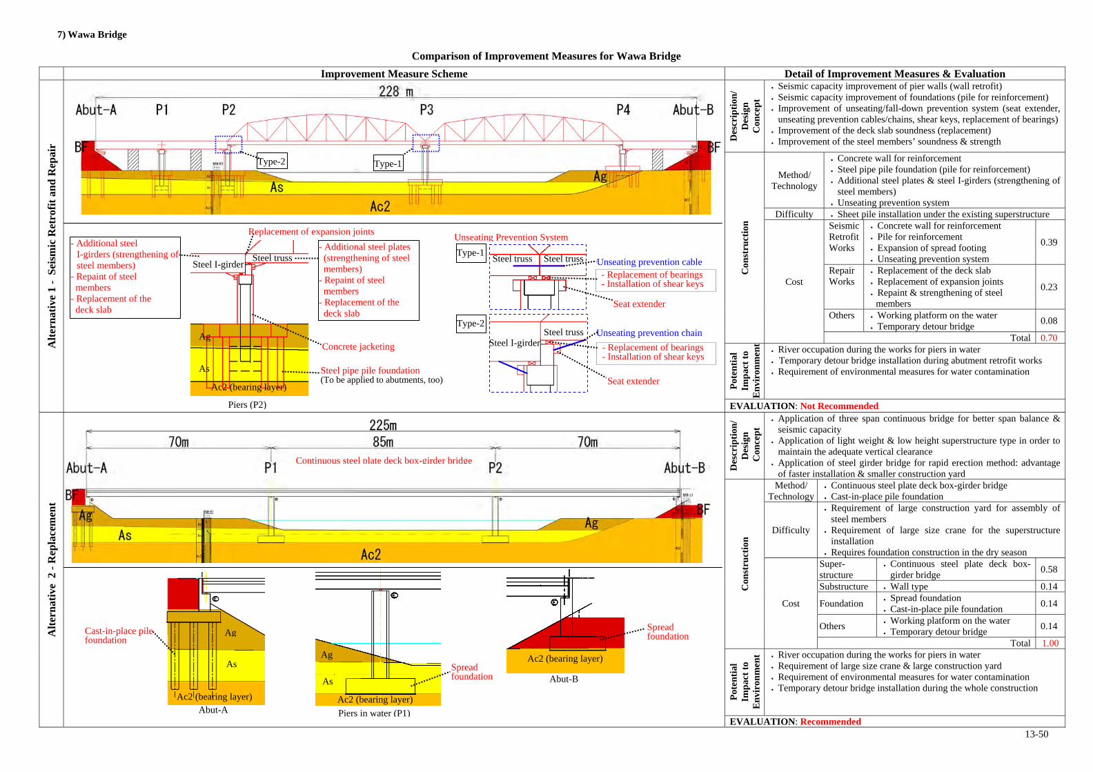
13-50
7) Wawa Bridge
Comparison of Improvement Measures for Wawa Bridge
Improvement Measure Scheme Detail of Improvement Measures & Evaluation
Alt
ern
ativ
e 1
- S
eism
ic R
etro
fit
and
Rep
air
Des
crip
tion
/ D
esig
n
Con
cep
t
Seismic capacity improvement of pier walls (wall retrofit) Seismic capacity improvement of foundations (pile for reinforcement) Improvement of unseating/fall-down prevention system (seat extender,
unseating prevention cables/chains, shear keys, replacement of bearings) Improvement of the deck slab soundness (replacement) Improvement of the steel members’ soundness & strength
Con
stru
ctio
n
Method/ Technology
Concrete wall for reinforcement Steel pipe pile foundation (pile for reinforcement) Additional steel plates & steel I-girders (strengthening of
steel members) Unseating prevention system
Difficulty Sheet pile installation under the existing superstructure
Cost
Seismic Retrofit Works
Concrete wall for reinforcement Pile for reinforcement Expansion of spread footing Unseating prevention system
0.39
Repair Works
Replacement of the deck slab Replacement of expansion joints Repaint & strengthening of steel
members
0.23
Others Working platform on the water Temporary detour bridge
0.08
Total 0.70
Pot
enti
al
Imp
act
to
En
viro
nm
ent
River occupation during the works for piers in water Temporary detour bridge installation during abutment retrofit works Requirement of environmental measures for water contamination
EVALUATION: Not Recommended
Alt
ern
ativ
e 2
- R
epla
cem
ent
Des
crip
tion
/ D
esig
n
Con
cep
t
Application of three span continuous bridge for better span balance & seismic capacity
Application of light weight & low height superstructure type in order to maintain the adequate vertical clearance
Application of steel girder bridge for rapid erection method: advantage of faster installation & smaller construction yard
Con
stru
ctio
n
Method/ Technology
Continuous steel plate deck box-girder bridge Cast-in-place pile foundation
Difficulty
Requirement of large construction yard for assembly of steel members
Requirement of large size crane for the superstructure installation
Requires foundation construction in the dry season
Cost
Super- structure
Continuous steel plate deck box-girder bridge
0.58
Substructure Wall type 0.14
Foundation Spread foundation Cast-in-place pile foundation
0.14
Others Working platform on the water Temporary detour bridge
0.14
Total 1.00
Pot
enti
al
Imp
act
to
En
viro
nm
ent River occupation during the works for piers in water
Requirement of large size crane & large construction yard Requirement of environmental measures for water contamination Temporary detour bridge installation during the whole construction
EVALUATION: Recommended
Type-1
Type-2Steel truss
Steel I-girder
Steel truss Steel truss
Unseating Prevention System
Unseating prevention cable
Seat extender
- Replacement of bearings- Installation of shear keys
Seat extender
Unseating prevention chain
- Replacement of bearings- Installation of shear keys
Type-2 Type-1
As
Concrete jacketing
Steel pipe pile foundation (To be applied to abutments, too)
Steel I-girder Steel truss
- Additional steel I-girders (strengthening of steel members)
- Repaint of steel members
- Replacement of the deck slab
- Additional steel plates (strengthening of steel members)
- Repaint of steel members
- Replacement of the deck slab
Ag
Piers (P2)
Replacement of expansion joints
Ac2 (bearing layer)
Cast-in-place pile foundation
Abut-A
Continuous steel plate deck box-girder bridge
Ac2 (bearing layer) Ac2 (bearing layer)
As
Ag
Ag
As Abut-B
Ac2 (bearing layer)
Piers in water (P1)
Spread foundation
Spread foundation

14-1
CHAPTER 14 RECOMMENDATION ON TARGET BRIDGES FOR THE OUTLINE DESIGN
14.1 Prioritization of Bridges with Evaluation Criteria for the Second Screening
With the evaluation criteria for the second screening established in Section 11.5, evaluation for each bridge was carried out as shown in Table 14.1-2 - Table 14.1-13. Table 14.1-1 shows summary of evaluation results with priority ranking for each bridge.

14-2
Table 14.1-1 Summary of Evaluation Results and Priority Ranking for Package B and C
EarthquakeResistingSystem
(20 points)
Unseating/Fall-downPrevention
System(15 points)
Foundation(15 points)
SeismicHazard
(10 points)
Super-structures(15 points)
Sub-Structures(5 points)
TrafficVolume
(5 points)
AlternativeBridge
(15 points)
1. Delpan Br. 15 9 15 0 7 3 49 3 5 57 4
2. Nagtahan Br. 11 8 12 3 7 3 44 3 5 52 5
3. Lambingan Br. 17 13 12 3 12 3 60 0 10 70 2
4. Guadalupe Br. 17 13 12 6 12 3 63 5 10 78 1
5. Marikina Br. 11 13 12 10 4 3 53 3 10 66 3
EarthquakeResistingSystem
(20 points)
Unseating/Fall-downPrevention
System(15 points)
Foundation(15 points)
SeismicHazard
(10 points)
Super-structures(15 points)
Sub-Structures(5 points)
TrafficVolume
(5 points)
AlternativeBridge
(15 points)
1. Buntun Br. 14 13 15 0 1 0 43 5 15 63 6
2. 1st Mandaue-Mactan Br. 18 13 14 0 8 5 58 5 5 68 4
3. Palanit Br. 17 15 3 3 15 3 56 0 15 71 3
4. Mawo Br. 14 11 14 10 9 0 58 3 15 76 1
5. Biliran Br. 14 11 3 6 6 3 43 3 15 61 7
6. Lilo-an Br. 14 15 3 6 7 3 48 3 15 66 5
7. Wawa Br. 17 13 5 10 14 0 59 3 10 72 2
Bridge NameTotal Score(100 points)
Importance(20 points)
Package B
Seismic Vulnerability(60 points)
Bridge Condition (80 points)Structural Soundness
(20 points)PriorityRanking
Sub-TotalScore
(80 points)
Package C
Bridge Name
Bridge Condition (80 points) Importance(20 points)
Total Score(100 points)
PriorityRanking
Seismic Vulnerability(60 points)
Structural Soundness(20 points)
Sub-TotalScore
(80 points)

14-3
Table 14.1-2 Delpan Bridge (Package B) Evaluation Score
2 Soil Type I (or II) and II (or III) 13 Simply supported 35 Balance Ratio: 1.0 - 1.5 33 Single column/wall 32 0 - 5.0 m 05 1992 and earlier 5
20
5 Poor 3
5 Moderate 35 Short 3
153 Unknown 33 With evidence or potential for scouring 33 Soil type III (Soft) 36 Very high 6
15
6010 Moderate (Need for repair work) 52 Moderate (Need for repair work) 13 Moderate (Need for repair work) 1
155 Moderate (Repairable) 35
20805 50,000 - 100,0000 pcu 3
15 1 km - 3 km away 520
100
1. Difference in soil types between adjacent piers Soil type: II or IIIRemarks (Reasons)Evaluation Item
Seis
mic
Vul
nera
bili
ty (
60 p
oint
s)
Bri
dge
Con
diti
on (
80 p
oint
s)
Sub-Total (Bridge Condition)
Stru
ctur
al S
ound
ness
(20
poin
ts)
Sub-Total (Structural Soundness)
EarthquakeResisting System
(20 points)
3. Eccentric Loads (longitudinal and transverse dir.) Balance Ratio: 1.32. Continuous or Simply Supported Bridge Center span with gerber hinges & end spans
5. Height of Abutment (Embankment) Embankment height: 8.0m4. Pier Type (Single column/wall or multiple columns)
Sub-Total
7. Unseating/Fall-down Prevention Devices
6. Built Year Built year: 1965
Sub-Total9. Seat Length
Seismic restrainers are installed, but notfunctionable enough.
8. Bearing Deterioration of bearings
9
11. Scouring Scouring at Pier-510. Foundation Type (known or unknown)
13. Liquefaction Potential Sand or silty sand (less than 10 of N value)12. Soil Type
Sub-Total
14. Distance from Active Faults 10 Small (Over 10.0 km)
Cracking & water leaking2. Secondary Members Water leaking at expansion joints
Sub-Total (Seismic Vulnerability)1. Primary Members Cracking
Superstructures(15 points)
10Sub-Total
7Sub-Total4. Deterioration of Columns/Walls Cracking
3. Deck Slab
Distance to the active fault: 11.1km
15
15
The seat lengths satisfy AASHTO criteria.
0
57
49
Distance to the altenative bridge: 1.7kmEvaluated by the criteria for Package B
Grand Total8
39
2. Alternative Bridge1. Traffic Volume
Sub-Total (Importance)
3Substructures
(5 points)
Foundation(15 points)
Unseating/Fall-down Prevention
System (15 points)
Seismic Hazard(10 points)
Importance (20 points)

14-4
Table 14.1-3 Nagtahan Bridge (Package B) Evaluation Score
2 Same 03 Continuous 05 Balance Ratio: 1.0 - 1.5 33 Single column/wall 32 0 - 5.0 m 05 1992 and earlier 5
20
5 Poor 3
5 Serious 55 Enough 0
153 Unknown 33 With evidence or potential for scouring 33 Soil type II (Moderate) 26 High 4
15
6010 Moderate (Need for repair work) 52 Moderate (Need for repair work) 13 Moderate (Need for repair work) 1
155 Moderate (Repairable) 35
20805 50,000 - 100,0000 pcu 3
15 1 km - 3 km away 520
100
1. Difference in soil types between adjacent piers Consistent soil typeRemarks (Reasons)Evaluation Item
3. Eccentric Loads (longitudinal and transverse dir.) Balance Ratio: 1.32. Continuous or Simply Supported Bridge
5. Height of Abutment (Embankment) Embankment height: 3.0m4. Pier Type (Single column/wall or multiple columns)
Sub-Total
7. Unseating/Fall-down Prevention Devices
6. Built Year Built year: 1966
Sub-Total9. Seat Length
Seismic restrainers are installed, but notfunctionable enough.
8. Bearing Loose connection of bearings
8
11. Scouring Potential of deep scouring at Pier-9 & 1010. Foundation Type (known or unknown)
13. Liquefaction Potential Sand or silty sand (10 - 20)12. Soil Type
Sub-Total
14. Distance from Active Faults 10Moderate (5.0 km - less than or equal10.0 km)
Sub-Total (Seismic Vulnerability)1. Primary Members Paint deterioration
Superstructures(15 points) Cracking & water leaking
7
2. Secondary Members Paint deterioration
10Sub-Total
Sub-Total4. Deterioration of Columns/Walls Section loss & rebar exposure
Distance to the active fault: 7.5km
11
12
The seat lengths satisfy JRA criteria.
52
44
Distance to the altenative bridge: 2.4kmEvaluated by the criteria for Package B
Importance (20 points)
3
Grand Total8
34
2. Alternative Bridge1. Traffic Volume
Sub-Total (Importance)
3
3. Deck Slab
Substructures (5 points)
Seis
mic
Vul
nera
bilit
y (
60 p
oint
s)
Bri
dge
Con
diti
on (
80 p
oint
s)
Sub-Total (Bridge Condition)
Stru
ctur
al S
ound
ness
(20
poin
ts)
Sub-Total (Structural Soundness)
EarthquakeResisting System
(20 points)
Foundation(15 points)
Unseating/Fall-down Prevention
System (15 points)
Seismic Hazard(10 points)

14-5
Table 14.1-4 Lambingan Bridge (Package B) Evaluation Score
2 Same 03 Simply supported 35 Balance Ratio: over 1.5 53 Single column/wall 32 5.0 - 10.0 m 15 1992 and earlier 5
20
5 Poor 3
5 Serious 55 Very Short 5
153 Unknown 33 With evidence or potential for scouring 33 Soil type II (Moderate) 26 High 4
15
6010 Serious (Need for reinforcement) 102 Moderate (Need for repair work) 13 Moderate (Need for repair work) 1
155 Moderate (Repairable) 35
20805 Less than 50,000 pcu 0
15 3 km - 10 km away 1020
100
1. Difference in soil types between adjacent piers Consistent soil typeRemarks (Reasons)Evaluation Item
3. Eccentric Loads (longitudinal and transverse dir.) Balance Ratio: 3.32. Continuous or Simply Supported Bridge Center span with gerber hinges
5. Height of Abutment (Embankment) Embankment height: 5.0m4. Pier Type (Single column/wall or multiple columns)
Sub-Total
7. Unseating/Fall-down Prevention Devices
6. Built Year Built year: 197517
Sub-Total9. Seat Length
Seismic restrainers are installed, but notfunctionable enough.
8. Bearing Deterioration of bearings
13
11. Scouring Scouring at Pier 210. Foundation Type (known or unknown)
13. Liquefaction Potential Sand or silty sand (10 - 20)12. Soil Type
Sub-Total
14. Distance from Active Faults 10Moderate (5.0 km - less than or equal10.0 km)
12
Section loss of RC side blocks
Sub-Total (Seismic Vulnerability)1. Primary Members Large deflection, uplift, & cracking
Superstructures(15 points)
15Sub-Total
Distance to the active fault: 5.3km
4. Deterioration of Columns/Walls Cracking and scaling/spalling
3. Deck Slab Cracking & water leaking12
2. Secondary Members
Some of seat lengths don’t satisfy AASHTO
70
60
Distance to the altenative bridge: 3.7kmEvaluated by the criteria for Package B
Importance (20 points)
3
Grand Total10
45
2. Alternative Bridge1. Traffic Volume
Sub-Total (Importance)
3
Sub-TotalSubstructures
(5 points)
Seis
mic
Vul
nera
bili
ty (
60 p
oint
s)
Bri
dge
Con
diti
on (
80 p
oint
s)
Sub-Total (Bridge Condition)
Str
uctu
ral S
ound
ness
(20
poin
ts)
Sub-Total (Structural Soundness)
EarthquakeResisting System
(20 points)
Foundation(15 points)
Unseating/Fall-down Prevention
System (15 points)
Seismic Hazard(10 points)

14-6
Table 14.1-5 Guadalupe Bridge (Package B) Evaluation Score
2 Soil Type I and III 23 Simply supported 35 Balance Ratio: 1.0 - 1.5 33 Single column/wall 32 5.0 - 10.0 m 15 1992 and earlier 5
20
5 Poor 3
5 Serious 55 Very Short 5
153 Unknown 33 With evidence or potential for scouring 33 Soil type II (Moderate) 26 High 4
15
60
10 Serious (Need for reinforcement) 10
2 Moderate (Need for repair work) 1
3 Moderate (Need for repair work) 1155 Moderate (Repairable) 35
20805 Over 100,000 pcu 5
15 3 km - 10 km away 1020
100
Substructures (5 points)
Sei
smic
Vul
nera
bilit
y (
60 p
oint
s)
Bri
dge
Con
ditio
n (
80 p
oint
s)
Sub-Total (Bridge Condition)
Stru
ctur
al S
ound
ness
(20
poin
ts)
Sub-Total (Structural Soundness)
EarthquakeResisting System
(20 points)
Foundation(15 points)
Unseating/Fall-down Prevention
System (15 points)
Seismic Hazard(10 points)
Importance (20 points)
6
Grand Total15
48
2. Alternative Bridge1. Traffic Volume
Sub-Total (Importance)
3
Sub-Total
78
63
Distance to the altenative bridge: 3.7kmEvaluated by the criteria for Package B
Distance to the active fault: 2.4km
17
12
Some of seat lengths don’t satisfy AASHTO
15Sub-Total
4. Deterioration of Columns/Walls Cracking, spalling, and rebar exposure
2. Secondary Members- Paint deterioration on steel truss members- Abnormal spacing of an expansion joint
Sub-Total (Seismic Vulnerability)
1. Primary Members- Paint deterioration on steel truss members- Major cracking at gerber hinge area of PCDG
Superstructures(15 points)
3. Deck Slab Cracking & water leaking12
Sub-Total
14. Distance from Active Faults 10Serious (2.0 km - less than or equal 5.0km)
13. Liquefaction Potential Sand or silty sand (10 - 20)12. Soil Type11. Scouring Potential of deep scouring at Pier-1 & 210. Foundation Type (known or unknown)
Sub-Total9. Seat Length
Seismic restrainers are installed, but notfunctionable enough.
8. Bearing Deterioration of bearings
13
Sub-Total
7. Unseating/Fall-down Prevention Devices
6. Built Year Built year: Steel truss: 1962, PC girders: 19785. Height of Abutment (Embankment) Embankment height: 8.0m4. Pier Type (Single column/wall or multiple columns)3. Eccentric Loads (longitudinal and transverse dir.) Balance Ratio: 1.22. Continuous or Simply Supported Bridge Center span with gerber hinges1. Difference in soil types between adjacent piers Soil type: I or III
Remarks (Reasons)Evaluation Item

14-7
Table 14.1-6 Marikina Bridge (Package B) Evaluation Score
2 Same 03 Simply supported 35 Balance Ratio: 1.0 - 1.5 33 Multiple columns 02 0 - 5.0 m 05 1992 and earlier 5
205 None 55 Serious 55 Short 3
153 Unknown 33 With evidence or potential for scouring 33 Soil type II (Moderate) 26 High 4
15
6010 Good or small (No need for repair) 0
2 Moderate (Need for repair work) 1
3 Serious (Need for replacement) 3155 Moderate (Repairable) 35
20805 50,000 - 100,0000 pcu 3
15 3 km - 10 km away 1020
100
Substructures (5 points)
Sei
smic
Vul
nera
bili
ty (
60 p
oint
s)
Bri
dge
Con
diti
on (
80 p
oint
s)
Sub-Total (Bridge Condition)
Stru
ctur
al S
ound
ness
(20
poin
ts)
Sub-Total (Structural Soundness)
EarthquakeResisting System
(20 points)
Foundation(15 points)
Unseating/Fall-down Prevention
System (15 points)
Seismic Hazard(10 points)
Importance (20 points)
10
Grand Total13
46
2. Alternative Bridge1. Traffic Volume
Sub-Total (Importance)
3
Sub-Total
The seat lengths satisfy AASHTO criteria.
66
53
Distance to the altenative bridge: 3.7kmEvaluated by the criteria for Package B
7Sub-Total
Distance to the active fault: 1.0km
4. Deterioration of Columns/Walls
3. Deck Slab Cracking & water leaking4
2. Secondary Members- Deterioration of cross beams- Water leaking at expansion joint
Sub-Total (Seismic Vulnerability)1. Primary Members
Superstructures(15 points)
Sub-Total
14. Distance from Active Faults 10 Fatal (Less than or equal 2.0 km)
1213. Liquefaction Potential Sand or silty sand (10 - 20)12. Soil Type11. Scouring Scouring at Pier-2 & 310. Foundation Type (known or unknown)
Sub-Total9. Seat Length
No seismic restrainers are installed.8. Bearing No bearings at piers
13
Sub-Total7. Unseating/Fall-down Prevention Devices
6. Built Year Built year: 198011
5. Height of Abutment (Embankment) Embankment height: 2.5m4. Pier Type (Single column/wall or multiple columns)3. Eccentric Loads (longitudinal and transverse dir.) Balance Ratio: 1.32. Continuous or Simply Supported Bridge1. Difference in soil types between adjacent piers Consistent soil type
Remarks (Reasons)Evaluation Item

14-8
Table 14.1-7 Buntun Bridge (Package C) Evaluation Score
2 Same 03 Simply supported 35 Balance Ratio: over 1.5 53 Multiple columns 02 5.0 - 10.0 m 15 1992 and earlier 5
205 None 5
5 Serious 5
5 Short 3153 Unknown 33 With evidence or potential for scouring 33 Soil type III (Soft) 36 Very high 6
15
6010 Good or small (No need for repair) 02 Good or small (No need for repair) 03 Moderate (Need for repair work) 1
155 Good or small (No need for repair) 05
20805 Over 5,000 pcu 5
15 More than 10 km away or no alternate bridge 1520
100
1. Difference in soil types between adjacent piers Consistent soil typeRemarks (Reasons)Evaluation Item
3. Eccentric Loads (longitudinal and transverse dir.) Balance Ratio: 1.72. Continuous or Simply Supported Bridge
5. Height of Abutment (Embankment) Embankment height: 3.0m4. Pier Type (Single column/wall or multiple columns)
Sub-Total7. Unseating/Fall-down Prevention Devices
6. Built Year Built year: 1967
Sub-Total9. Seat Length
No seismic restrainers are installed.
8. Bearing Pin portion of bearing is missing at Pier-11.
13
11. Scouring Scouring at Pier-510. Foundation Type (known or unknown)
13. Liquefaction Potential Sand or silty sand (less than 10 of N value)12. Soil Type
Sub-Total
14. Distance from Active Faults 10 Small (Over 10.0 km)
2. Secondary Members
Sub-Total (Seismic Vulnerability)1. Primary Members
Superstructures(15 points)
4. Deterioration of Columns/Walls
3. Deck Slab Minor cracking & water leaking1
1Sub-Total
Distance to the active fault: 15.9km
14
15
The seat lengths satisfy AASHTO criteria.
63
43
Distance to the altenative bridge: 13kmEvaluated by the criteria for Package C
Importance (20 points)
0
Grand Total20
42
2. Alternative Bridge1. Traffic Volume
Sub-Total (Importance)
0
Sub-TotalSubstructures
(5 points)
Seis
mic
Vul
nera
bili
ty (
60 p
oint
s)
Bri
dge
Con
diti
on (
80 p
oint
s)
Sub-Total (Bridge Condition)
Stru
ctur
al S
ound
ness
(20
poin
ts)
Sub-Total (Structural Soundness)
EarthquakeResisting System
(20 points)
Foundation(15 points)
Unseating/Fall-down Prevention
System (15 points)
Seismic Hazard(10 points)

14-9
Table 14.1-8 1st Mandaue-Mactan Bridge (Package C) Evaluation Score
2 Soil Type I (or II) and II (or III) 13 Simply supported 35 Balance Ratio: over 1.5 53 Single column/wall 32 5.0 - 10.0 m 15 1992 and earlier 5
205 None 55 Serious 55 Short 3
153 Unknown 33 With evidence or potential for scouring 33 Soil type II (Moderate) 26 Very high 6
15
6010 Moderate (Need for repair work) 52 Serious (Need for reinforcement) 23 Moderate (Need for repair work) 1
15
5 Serious (Not repairable) 5
520805 Over 5,000 pcu 5
15 1 km - 3 km away 520
100
Substructures (5 points)
Seis
mic
Vul
nera
bili
ty (
60 p
oint
s)
Bri
dge
Con
diti
on (
80 p
oint
s)
Sub-Total (Bridge Condition)
Stru
ctur
al S
ound
ness
(20
poin
ts)
Sub-Total (Structural Soundness)
EarthquakeResisting System
(20 points)
Foundation(15 points)
Unseating/Fall-down Prevention
System (15 points)
Seismic Hazard(10 points)
Importance (20 points)
0
Grand Total10
45
2. Alternative Bridge1. Traffic Volume
Sub-Total (Importance)
5
Sub-Total
68
58
Distance to the altenative bridge: 1.3kmEvaluated by the criteria for Package C
Distance to the active fault: 15.8km
18
14
The seat lengths satisfy AASHTO criteria.
13Sub-Total
4. Deterioration of Columns/Walls- Experience of ship crush at Pier-7- Severe rebar exposure at pile caps in water
3. Deck Slab Minor cracking & rebar exposure8
2. Secondary Members Heavy corrosion & section loss
Sub-Total (Seismic Vulnerability)1. Primary Members Experience of ship crush
Superstructures(15 points)
Sub-Total
14. Distance from Active Faults 10 Small (Over 10.0 km)
13. Liquefaction Potential Sand or silty sand (less than 10 of N value)12. Soil Type11. Scouring Scouring at Pier-1010. Foundation Type (known or unknown)
Sub-Total9. Seat Length
No seismic restrainers are installed.8. Bearing Deterioration of bearings
13
Sub-Total7. Unseating/Fall-down Prevention Devices
6. Built Year Built year: 19725. Height of Abutment (Embankment) Embankment height: 4.0m4. Pier Type (Single column/wall or multiple columns)3. Eccentric Loads (longitudinal and transverse dir.) Balance Ratio: 2.22. Continuous or Simply Supported Bridge1. Difference in soil types between adjacent piers Soil type: I or II
Remarks (Reasons)Evaluation Item

14-10
Table 14.1-9 Palanit Bridge (Package C) Evaluation Score
2 Same 03 Simply supported 35 Balance Ratio: over 1.5 53 Single column/wall 32 5.0 - 10.0 m 15 1992 and earlier 5
205 None 55 Serious 55 Very Short 5
153 Unknown 33 None 03 Soil type I (Firm) 06 None 0
15
60
10 Serious (Need for reinforcement) 10
2 Serious (Need for reinforcement) 23 Serious (Need for replacement) 3
15
5 Moderate (Repairable) 3
520805 Less than 2,000 pcu 0
15 More than 10 km away or no alternate bridge 1520
100
1. Difference in soil types between adjacent piers Consistent soil typeRemarks (Reasons)Evaluation Item
3. Eccentric Loads (longitudinal and transverse dir.) Balance Ratio: 2.72. Continuous or Simply Supported Bridge
5. Height of Abutment (Embankment) Embankment height: 3.0m4. Pier Type (Single column/wall or multiple columns)
Sub-Total7. Unseating/Fall-down Prevention Devices
6. Built Year Built year: 1972
Sub-Total9. Seat Length
No seismic restrainers are installed.8. Bearing Deterioration of bearings
15
11. Scouring10. Foundation Type (known or unknown)
13. Liquefaction Potential Firm, clayey soil or over than 30 of N value12. Soil Type
Sub-Total
14. Distance from Active Faults 10Moderate (5.0 km - less than or equal 10.0km)
2. Secondary Members Severe corrosion
Sub-Total (Seismic Vulnerability)
1. Primary Members- Severe corrosion & section loss- Low load capacity (load limit: 7t)
Superstructures(15 points)
4. Deterioration of Columns/WallsRebar exposure & cracking at the bearingbase of Pier-1
3. Deck Slab Major cracking, water leaking, & hanycomb15
18Sub-Total
Distance to the active fault: 7.6km
17
3
Some of seat lengths don’t satisfy AASHTO
71
56
Distance to the altenative bridge: 20kmEvaluated by the criteria for Package C
Importance (20 points)
3
Grand Total15
38
2. Alternative Bridge1. Traffic Volume
Sub-Total (Importance)
3
Sub-Total
Substructures (5 points)
Seis
mic
Vul
nera
bili
ty (
60 p
oint
s)
Bri
dge
Con
diti
on (
80 p
oint
s)
Sub-Total (Bridge Condition)
Stru
ctur
al S
ound
ness
(20
poin
ts)
Sub-Total (Structural Soundness)
EarthquakeResisting System
(20 points)
Foundation(15 points)
Unseating/Fall-down Prevention
System (15 points)
Seismic Hazard(10 points)

14-11
Table 14.1-10 Mawo Bridge (Package C) Evaluation Score
2 Soil Type I and III 23 Simply supported 35 Balance Ratio: 1.0 03 Single column/wall 32 5.0 - 10.0 m 15 1992 and earlier 5
205 None 55 Moderate 35 Short 3
153 Unknown 33 Unknown 23 Soil type III (Soft) 36 Very high 6
15
60
10 Moderate (Need for repair work) 5
2 Moderate (Need for repair work) 1
3 Serious (Need for replacement) 3
155 Good or small (No need for repair) 05
20805 2,000 - 5,000 pcu 3
15 More than 10 km away or no alternate bridge 1520
100
Substructures (5 points)
Seis
mic
Vul
nera
bili
ty (
60 p
oint
s)
Bri
dge
Con
diti
on (
80 p
oint
s)
Sub-Total (Bridge Condition)
Stru
ctur
al S
ound
ness
(20
poin
ts)
Sub-Total (Structural Soundness)
EarthquakeResisting System
(20 points)
Foundation(15 points)
Unseating/Fall-down Prevention
System (15 points)
Seismic Hazard(10 points)
Importance (20 points)
10
Grand Total18
49
2. Alternative Bridge1. Traffic Volume
Sub-Total (Importance)
0
Sub-Total
76
58
Distance to the altenative bridge: 20kmEvaluated by the criteria for Package C
Distance to the active fault: 1.4km
14
14
The seat lengths satisfy AASHTO criteria.
9Sub-Total
4. Deterioration of Columns/Walls
3. Deck SlabCracking, water leaking, hanycomb, & rebarexposure
9
2. Secondary Members Painting deterioration & corrosion
Sub-Total (Seismic Vulnerability)
1. Primary Members- Painting deterioration & corrosion- Low load capacity (load limit: 7t)
Superstructures(15 points)
Sub-Total
14. Distance from Active Faults 10 Fatal (Less than or equal 2.0 km)
13. Liquefaction Potential Sand or silty sand (less than 10 of N value)12. Soil Type11. Scouring Condition of Pier-1 in water is unknown.10. Foundation Type (known or unknown)
Sub-Total9. Seat Length
No seismic restrainers are installed.8. Bearing Deterioration of bearings
11
Sub-Total7. Unseating/Fall-down Prevention Devices
6. Built Year Built year: 19765. Height of Abutment (Embankment) Embankment height: 2.0m4. Pier Type (Single column/wall or multiple columns)3. Eccentric Loads (longitudinal and transverse dir.) Balance Ratio: 1.02. Continuous or Simply Supported Bridge1. Difference in soil types between adjacent piers Soil type: I or III
Remarks (Reasons)Evaluation Item

14-12
Table 14.1-11 Biliran Bridge (Package C) Evaluation Score
2 Same 03 Simply supported 35 Balance Ratio: over 1.5 53 Multiple columns 02 5.0 - 10.0 m 15 1992 and earlier 520
5 Poor 3
5 Serious 55 Short 3153 Unknown 33 None 03 Soil type I (Firm) 06 None 015
6010 Moderate (Need for repair work) 52 Good or small (No need for repair) 03 Moderate (Need for repair work) 1155 Moderate (Repairable) 3520805 2,000 - 5,000 pcu 315 More than 10 km away or no alternate bridge 1520
100
1. Difference in soil types between adjacent piers Consistent soil typeRemarks (Reasons)Evaluation Item
3. Eccentric Loads (longitudinal and transverse dir.) Balance Ratio: 8.52. Continuous or Simply Supported Bridge
5. Height of Abutment (Embankment) Embankment height: 4.0m4. Pier Type (Single column/wall or multiple columns)
Sub-Total
7. Unseating/Fall-down Prevention Devices
6. Built Year Built year: 1976
Sub-Total9. Seat Length
Seismic restrainers are installed, but notfunctionable enough.
8. Bearing Deterioration of bearings
11
11. Scouring10. Foundation Type (known or unknown)
13. Liquefaction Potential Firm, clayey soil or over than 30 of N value12. Soil Type
Sub-Total
14. Distance from Active Faults 10 Serious (2.0 km - less than or equal 5.0 km)
2. Secondary Members
Sub-Total (Seismic Vulnerability)1. Primary Members Corrosion on steel I-girder members
Superstructures(15 points) 3. Deck Slab Spalling & water leaking
6
9Sub-Total
4. Deterioration of Columns/Walls Cracking
Distance to the active fault: 4.3km
14
3
The seat lengths satisfy AASHTO criteria.
61
43
Distance to the altenative bridge: No altenativeEvaluated by the criteria for Package C
Importance (20 points)
6
Grand Total18
34
2. Alternative Bridge1. Traffic Volume
Sub-Total (Importance)
3
Sub-TotalSubstructures
(5 points)
Sei
smic
Vul
nera
bili
ty (
60 p
oint
s)
Bri
dge
Con
diti
on (
80 p
oint
s)
Sub-Total (Bridge Condition)
Stru
ctur
al S
ound
ness
(20
poin
ts)
Sub-Total (Structural Soundness)
EarthquakeResisting System
(20 points)
Foundation(15 points)
Unseating/Fall-down Prevention
System (15 points)
Seismic Hazard(10 points)

14-13
Table 14.1-12 Lilo-an Bridge (Package C) Evaluation Score
2 Same 03 Simply supported 35 Balance Ratio: over 1.5 53 Multiple columns 02 5.0 - 10.0 m 15 1992 and earlier 5205 None 5
5 Serious 5
5 Very Short 5153 Unknown 33 None 03 Soil type I (Firm) 06 None 015
60
10 Moderate (Need for repair work) 5
2 Moderate (Need for repair work) 13 Moderate (Need for repair work) 1155 Moderate (Repairable) 3520805 2,000 - 5,000 pcu 315 More than 10 km away or no alternate bridge 1520
100
Substructures (5 points)
Sei
smic
Vul
nera
bili
ty (
60 p
oint
s)
Bri
dge
Con
diti
on (
80 p
oint
s)
Sub-Total (Bridge Condition)
Stru
ctur
al S
ound
ness
(20
poin
ts)
Sub-Total (Structural Soundness)
EarthquakeResisting System
(20 points)
Foundation(15 points)
Unseating/Fall-down Prevention
System (15 points)
Seismic Hazard(10 points)
Importance (20 points)
6
Grand Total18
38
2. Alternative Bridge1. Traffic Volume
Sub-Total (Importance)
3
Sub-Total
Some of seat lengths don’t satisfy AASHTO
66
48
Distance to the altenative bridge: No altenativeEvaluated by the criteria for Package C
10Sub-Total
Distance to the active fault: 2.5km
4. Deterioration of Columns/Walls Cracking & hanycomb
3. Deck Slab Cracking & hanycomb7
2. Secondary Members Corrosion & loose connection
Sub-Total (Seismic Vulnerability)
1. Primary Members- Corrosion on steel ranger arch members- Water leaking on PC-I girder members
Superstructures(15 points)
Sub-Total
14. Distance from Active Faults 10 Serious (2.0 km - less than or equal 5.0 km)
313. Liquefaction Potential Firm, clayey soil or over than 30 of N value12. Soil Type11. Scouring10. Foundation Type (known or unknown)
Sub-Total9. Seat Length
No seismic restrainers are installed.
8. Bearing Deterioration of bearings
15
Sub-Total7. Unseating/Fall-down Prevention Devices
6. Built Year Built year: 197914
5. Height of Abutment (Embankment) Embankment height: 4.0m4. Pier Type (Single column/wall or multiple columns)3. Eccentric Loads (longitudinal and transverse dir.) Balance Ratio: 3.92. Continuous or Simply Supported Bridge1. Difference in soil types between adjacent piers Consistent soil type
Remarks (Reasons)Evaluation Item

14-14
Table 14.1-13 Wawa Bridge (Package C) Evaluation Score
2 Same 03 Simply supported 35 Balance Ratio: over 1.5 53 Single column/wall 32 5.0 - 10.0 m 15 1992 and earlier 5205 None 5
5 Serious 5
5 Short 3153 Unknown 33 Unknown 23 Soil type I (Firm) 06 None 015
60
10 Serious (Need for reinforcement) 10
2 Moderate (Need for repair work) 13 Serious (Need for replacement) 3155 Good or small (No need for repair) 0520805 2,000 - 5,000 pcu 315 3 km - 10 km away 1020
100
1. Difference in soil types between adjacent piers Consistent soil typeRemarks (Reasons)Evaluation Item
Sei
smic
Vul
nera
bili
ty (
60 p
oint
s)
Bri
dge
Con
diti
on (
80 p
oint
s)
EarthquakeResisting System
(20 points)
Foundation(15 points)
Unseating/Fall-down Prevention
System (15 points)
Seismic Hazard(10 points)
3. Eccentric Loads (longitudinal and transverse dir.) Balance Ratio: 3.02. Continuous or Simply Supported Bridge
5. Height of Abutment (Embankment) Embankment height: 4.0m4. Pier Type (Single column/wall or multiple columns)
Sub-Total7. Unseating/Fall-down Prevention Devices
6. Built Year Built year: 196717
Sub-Total9. Seat Length
No seismic restrainers are installed.
8. BearingSeismically vulunerable bearing type &Deterioration of bearings
13
11. Scouring Condition of Pier-3 in water is unknown.10. Foundation Type (known or unknown)
13. Liquefaction Potential Firm, clayey soil or over than 30 of N value12. Soil Type
- Low load capacity (load limit: 10t)- Temporary suports for steel I-girders
Superstructures(15 points)
Sub-Total
Major cracking & water leaking14
Corrosion
Distance to the active fault: 5.5km
5
14Sub-Total
Sub-Total (Bridge Condition)
Str
uctu
ral S
ound
ness
(20
poin
ts)
Sub-Total (Structural Soundness)
2. Secondary Members
The seat lengths satisfy AASHTO criteria.
10Fatal (Less than or equal 2.0 km)
59
Distance to the altenative bridge: 6kmEvaluated by the criteria for Package C
Grand Total13
45
2. Alternative Bridge1. Traffic Volume
Sub-Total (Importance)
0
Sub-Total4. Deterioration of Columns/Walls
72
1014. Distance from Active Faults
Substructures (5 points)
Importance (20 points)
3. Deck Slab
Sub-Total (Seismic Vulnerability)
1. Primary Members

14-15
14.2 Recommendation of Target Bridge Selection for the Outline Design
14.2.1 Recommendation of Target Bridge Selection Based on the Second Screening
As the result of the 2nd screening evaluation, priority ranks and improvement measures of the target bridges are suggested as shown in Table 14.2-1. Based on the priority rank in the table, two bridges from Package B and five bridges from Package C are chosen with recommended improvement measures for outline design. However, further study on the comparison of improvement measures is necessary for Guadalupe Bridge and Mawo Bridge in the beginning of the outline design stage. - Guadalupe Bridge - The bridge ranked first in the 2nd screening of Package B. Immediate implementation of the appropriate improvement measure is recommended. Based on the result of improvement measure comparison, replacement is recommended for its cost-effectiveness. However, both the traffic regulation and the installation of temporary detour bridges for the replacement seem to be extremely difficult, considering the current traffic condition on the bridge. Further study should be taken in order to confirm the reality/unreality of the replacement. - Mawo Bridge - The bridge ranked first in the 2nd screening of Package C. Immediate implementation of the appropriate improvement measure is recommended. Based on the result of improvement measure comparison, seismic retrofit is more cost-effective than replacement. However, the replacement of Mawo Bridge is strongly recommended for the severe superstructure deterioration and the lack of load capacity. Further study should be taken in order to optimize the cost performance of the bridge replacement.

14-16
Table 14.2.1-1 Recommendation of Target Bridges for Outline Design
Note: * indicates the necessity of further study on the comparison of improvement measures.
Package B
Bridge Name
Priority Rank based on Seismic Vulnerability, Structural Soundness
and Importance
Recommended Improvement Measures
Recommendation for Outline Design
1. Delpan Br. 4 Seismic Retrofit
2. Nagtahan Br. 5 Seismic Retrofit
3. Lambingan Br. 2 Replacement Recommended
4. Guadalupe Br. 1 Replacement /
Seismic Retrofit* Recommended
5. Marikina Br. 3 Replacement
Package C
Bridge Name
Priority Rank based on Seismic Vulnerability,
Structural Soundness and Importance
Recommended Improvement Measures
Recommendation for Outline Design
1. Buntun Br. 6 Seismic Retrofit
2. 1st Mandaue-
Mactan Br. 4 Seismic Retrofit Recommended
3. Palanit Br. 3 Replacement Recommended
4. Mawo Br. 1 Replacement /
Seismic Retrofit* Recommended
5. Biliran Br. 7 Seismic Retrofit
6. Lilo-an Br. 5 Seismic Retrofit Recommended
7. Wawa Br. 2 Replacement Recommended

14-17
14.2.2 Detail Comparative Study on Improvement Measure Scheme Selection for Guadalupe Bridge & Mawo Bridge
(1) Background and Objective of the Study
As the result of the 2nd screening evaluation, seven target bridges were selected for outline design, based on their priority ranks. While five target bridges out of seven were selected with recommended improvement measure schemes (i.e. either replacement or seismic retrofit) at the time, improvement measure schemes of Guadalupe Bridge and Mawo Bridge remained undecided, for the two target bridges needed more detail study for the decision. The objectives of comparative studies for the two bridges are as follows. - Guadalupe Bridge - Based on the result of the 2nd screening evaluation, replacement is recommended as the improvement measure scheme of Guadalupe Bridge for its cost-effectiveness: the cost of seismic retrofit plan is assumed to be over 60% of the cost of replacement plan. However, both the traffic regulation and the installation of temporary detour bridges for the replacement seem to be extremely difficult, considering the current traffic condition of EDSA Ave. and the condition of neighborhood with buildings lined close together. The objective of detail comparative study here is to select the realistic improvement measure scheme for the bridge in consideration of construction planning and other restrictive conditions. - Mawo Bridge - Based on the result of the 2nd screening evaluation, seismic retrofit is more cost-effective than replacement for the improvement measure scheme of Mawo Bridge. However, the replacement of Mawo Bridge is strongly recommended for the severe superstructure deterioration and the lack of load capacity. Also, it’s better to change the bridge type from existing steel type to concrete type for the advantage of maintenance-free structure, which is the request from DPWH district office in charge of the bridge. The objective of detail comparative study here is to optimize the bridge type of the replacement plan and confirm its cost-effectiveness for the implementation. (2) Detail Comparative Study on Improvement Measure Scheme Selection for Guadalupe
Bridge
1) Outline of the Comparative Study
The outline of the comparative study on improvement measure schemes for Guadalupe Bridge is shown in the following flowchart.

14-18
Figure 14.2.2-1 Flowchart of Comparative Study on Improvement Measure Scheme Selection
1. Confirmation of construction feasibility of Outer Bridges (more prioritized) (Construction difficulties) - Demolition of existing piers - Reconstruction of piers neighboring existing piers
Confirmation of structural characteristics
Outer Bridges (1979) (both sides of Inner Bridge) Confirmed to be more prioritized for improvement - 3-span Gerber-hinge-supported PC-I girder bridge (Seismically vulnerable at Gerber hinge supports) - Wall type substructures designed by old code (Need of seismic retrofit by latest codes)
- Unknown foundation designed by old code (No consideration of liquefaction effect)
Inner Bridge (1962) - 3-span continuous steel trussed-girder bridge (Seismically advantageous structure) - Wall type substructures designed by old code (Need of seismic retrofit by latest codes)
- Unknown foundation designed by old code (No consideration of liquefaction effect)
2. Confirmation of construction feasibility of Inner Bridge (less prioritized) (Construction difficulties) - Temporarily supporting of existing superstructure during pier reconstructions - Traffic regulation during soil improvement works behind abutments
Target for Improvement: Guadalupe Bridge
Inner Bridge needs of consideration for - National heritage preservation (construction year: 1962:
over 50 years after the construction) - Traffic regulation difficulty - Appropriate navigation clearance maintenance - Land acquisition difficulty - Relocation of a power pole for high-voltage cable
Outer Bridges need of consideration for - Traffic regulation difficulty - Appropriate navigation clearance maintenance - Land acquisition difficulty
Confirmation of restrictive conditions for planning
Note: The above plans will be examined and optimized in outline design.
1. Comparative study for Outer Bridges (more prioritized for improvement) Selected improvement measure scheme: Replacement - 3-span continuous steel plate deck box-girder bridge - Wall type substructures - Steel pipe sheet pile foundation
Improvement measure scheme selection (“Replacement” or “Seismic retrofit”)
Feasibility study on construction planning
Outline design
2. Comparative study for Inner Bridge (less prioritized for improvement)
Selected improvement measure scheme: Seismic retrofit - Total reconstruction of Pier-1 & Pier-2 (steel pipe sheet pile foundation) - Soil Improvement (earth pressure reduction) for Abutment-B - Soil Improvement (liquefaction prevention) for Abutment-B - Unseating prevention system

14-19
2) Confirmation of Structural Characteristics of Inner Bridge and Outer Bridges
As a first step to selection of improvement measure schemes, structural characteristics of Inner Bridge and Outer Bridges are confirmed. As a result, Outer Bridges are found to be more prioritized for structural improvement than Inner Bridge for more sever structural deficiencies and higher risks for unseating under large-scale earthquakes. The structural characteristics of Inner Bridge and Outer Bridges are summarized as follows.
Inner Bridge was constructed in 1962. The bridge type is “3-span continuous steel trussed girder bridge”, which is seismically advantageous structure except for only bearing restraint condition of Pier-1 is “Fixed”: Pier-1 undertakes all the superstructure weight under earthquake. The superstructure soundness is relatively acceptable and can be used for some more decades. Substructures are wall type with unknown foundation structures and were designed by non-seismic design code. What is worse, the site has a liquefiable layer and the effect was not considered in the design. The substructures need improvement works for thin wall bodies and unknown foundations. Moreover, unseating prevention system should be installed for “earthquake-proof safety” just in case of substructures’ collapse. Inner Bridge was constructed in 1962. Outer Bridges were constructed in 1979 on both sides of Inner Bridge in order to increase number of lanes and mitigate traffic congestion. The bridge type is 3-span Gerber-hinge-supported PC-I girder bridge, which is seismically advantageous structure except for only bearing restraint condition of Pier-1 is “Fixed” as well as Inner Bridge. The difference is that the concrete structure has serious shear cracks in Gerber hinge portions, which could cause bridge fall-down under large-scale earthquakes. Need of improvement work for the serious shear cracks makes Outer Bridges more prioritized for structural improvement planning than Inner Bridge. The characteristics and structural problems of substructures are same as those of Inner Bridge. However, piers in the river have cracks and section-loss around the bottom of columns hit by vessels barges. The column damages could induce collapse of piers pushed by large seismic inertial force. This is also the reason to make Outer Bridges more prioritized. Based on the above structural differences, the improvement measure schemes of Inner Bridge and Outer Bridges will be studied separately, prioritizing the planning of Outer Bridges. The structural characteristics of Inner Bridge and Outer Bridges are illustrated in the next page.
Inner Bridge (1962) - 3-span continuous steel trussed girder bridge (Seismically advantageous structure) - Wall type substructures designed by old code
(Need of seismic retrofit by latest codes) - Unknown foundation designed by old code
(No consideration of liquefaction effect)
Structural Characteristics
Outer Bridges (1979) (both sides of Inner Bridge) Confirmed to be more prioritized for improvement- 3-span Gerber-hinge-supported PC I-girder bridge (Seismically vulnerable at Gerber hinge supports) - Wall type substructures designed by old code
(Need of seismic retrofit by latest codes) - Unknown foundation designed by old code
(No consideration of liquefaction effect)

14-20
Figure 14.2.2-2 The Structural Characteristics of Inner Bridge and Outer Bridges
3) Confirmation of Restrictive Conditions for Planning
a) Summary of Restrictive Conditions for Planning
The following restrictive conditions must be considered in the planning of improvement works for Inner Bridge and Outer Bridges.
Note: underground structures are unknown: assumed
Profile (Outer Bridges)
Plan
To Pasay City To Quezon City
Inner Bridge (6 lanes)
Outer Bridge (2 lanes): More prioritized
Boundary of structural independency- Superstructures: Separated - Wall type substructure: Separated - Pile cap: Connected
Outer Bridge (2 lanes): More prioritized
Profile (Inner Bridge)
Note: underground structures are unknown: assumed
3-span continuous steel trussed girder bridge
3-span Gerber-hinge-supported PC I-girder bridge
Boundary of bearing layer

14-21
b) Restrictive Conditions for Planning of Inner Bridge
In the Inner Bridge planning, the following restrictive considerations must be considered.
(I) National heritage preservation (construction year: 1962: over 50 years after the construction)
As shown below, a law for national heritage preservation was enforced in 2009. For the purpose of protecting bridges as cultural properties against modification or demolition, bridges older than 50 years old are strongly recommended for retrofitting instead of replacement. If replacement is demanded for those bridges, approval from the authorized organization is required. In case of Guadalupe Bridge, the law shall be applied to Inner Bridge, which was constructed in 1962.
Republic Act No. 10066
Figure 14.2.2-3 Law for National Heritage Preservation (Section 5)
(II) Traffic regulation difficulty As shown in the next table, traffic condition of Guadalupe Bridge, which consists of 10 lanes including 4 bus lanes, is extremely heavy thorough whole the day. As a result of traffic count survey conducted in this project, Annual Average Daily Traffic (AADT) is 220,446 veh/day and peak hour traffic volume is 14,366 veh/hour. As you can see in the following figure, hour traffic volume is constantly over 10,000veh/hour from 6:00am to 8:00pm. Based on the survey results, Level-of-Service (LOS) of the bridge is evaluated as “E”. According to the survey results, traffic regulation for Guadalupe Bridge improvement work seems to be extremely difficult. Construction planning with less effect on the traffic condition shall be considered.
Restrictive conditions of Inner Bridge are: 1) National heritage preservation (construction year:
1962: over 50 years after the construction) 2) Traffic regulation difficulty 3) Appropriate navigation clearance maintenance 4) Land acquisition difficulty 5) Relocation of a power pole for high-voltage cable
Restrictive conditions of Outer Bridges are: 1) Traffic regulation difficulty 2) Appropriate navigation clearance maintenance 3) Land acquisition difficulty
(snip)
Inner Bridge (1962): 51 years old as of 2013

14-22
Table 14.2.2-1 AADT Based on Traffic Count Survey Results
Motorcycle / Tricycle
Car / Taxi / Pick-up / Van
JeepneyLarge Bus
2-Axle Truck
3-Axle Truck
Truck trailer
Sub-Total
Total
Day 1 19,576 171,155 0 12,788 4,282 1,571 915 190,711 210,287
Day 2 19,538 191,000 0 13,669 3,917 1,684 837 211,107 230,645
AADT 19,557 181,078 0 13,229 4,100 1,628 876 200,909 220,466
Figure 14.2.2-4 Hourly Traffic Volume of Guadalupe Bridge
(III) Appropriate navigation clearance maintenance
The current navigation clearance is better to be maintained for vessels and barges going under the bridge. Even with the current condition, so many vessels have been hitting the bridge piers. Reduction of navigation clearance implies more collision of vessels to the piers in the future. If there’s any change of the clearance in “improvement measure planning”, approval from Coast Guard will be required. The current hydrological condition of Guadalupe Bridge is explained in detail below.
Figure 14.2.2-5 Current Hydrological Condition of Guadalupe Bridge
Navigation Clearance
P1 P2
H.T.L.: High Tide Level
M.W.L.: Mean Water Level
Protection for vessel collision
(%)1.1810077500
27000100
Width)(River
Width) Structure (Total Ratio)Inhibition(River
Note: - River Inhibition ratio is expected to be no more than 5% in the Japanese specification
- The above figure illustrates the condition of Outer Bridges: the condition of Inner Bridge is different
without vessel protection structure. The navigation width and river inhibition of Inner Bridge are 40,8m
and 4.9 %, respectively.
0
2,000
4,000
6,000
8,000
10,000
12,000
14,000
16,000
6:00
-7:0
0
7:00
-8:0
0
8:00
-9:0
0
9:00
-10:
00
10:0
0-11
:00
11:0
0-12
:00
12:0
0-13
:00
13:0
0-14
:00
14:0
0-15
:00
15:0
0-16
:00
16:0
0-17
:00
17:0
0-18
:00
18:0
0-19
:00
19:0
0-20
:00
20:0
0-21
:00
21:0
0-22
:00
22:0
0-23
:00
23:0
0-24
:00
24:0
0-1:
00
1:00
-2:0
0
2:00
-3:0
0
3:00
-4:0
0
4:00
-5:0
0
5:00
-6:0
0
Tra
ffic
Vol
ume
(Veh
/Day
)
Direction 1
Direction 2
Both
Continuous heavy traffic for 12 hours
Hourly Traffic Volume
DDDiiirrreeecccttt iiiooonnn 222
DDDiiirrreeecccttt iiiooonnn 111
Definition of traffic direction
Guadalupe BridgeTime
Extremely heavy traffic

14-23
(IV) Land acquisition difficulty, and
(V) Relocation of a power pole for high-voltage cable There’re so many potential obstacles for construction around Guadalupe Bridge. The vicinity of the bridge is very crowded with buildings and houses. Moreover, public structures such as power poles and large sign boards stand nearby the bridge. Therefore, installation of detour bridges can’t be done without temporary land acquisition. “The number of lanes during construction” and “degree of traffic regulation” must be carefully balanced in construction planning so as to prevent as much land acquisition as possible, which could result in the delay of project implementation.
Figure 14.2.2-6 Flowchart of Comparative Study on Improvement Measure Scheme Selection
c) Restrictive Conditions for Planning of Outer Bridges
In the Outer Bridge planning, the following restrictive considerations must be considered. i) Traffic regulation difficulty: same as Inner Bridge ii) Appropriate navigation clearance maintenance: same as Inner Bridge iii) Land acquisition difficulty: same as Inner Bridge
1
2
Buildings & houses to be concerned
1 2A power pole
Buildings & housesBuildings & houses behind the signboards
A power pole
Note: potential causes of land acquisition are; - Rising of vertical alignment - Installation of temporary detour bridge

14-24
4) Improvement Measure Scheme Selection (“Replacement” or “Seismic Retrofit”)
a) Comparative Study Procedure for the Selection
Comparative studies for improvement measure scheme selection were conducted with the following procedure, considering the improvement priorities of Inner Bridge and Outer Bridges. Outer Bridges are more prioritized than Inner Bridge, for their serious structural deficiencies in both superstructure and substructures must be urgently solved by improvement works. Therefore, construction results of Outer Bridges become one of restrictive conditions of planning for Inner Bridge: construction planning of Inner Bridge must be done in consideration of renewed shapes of Outer Bridges.
b) Evaluation Items Considered in the Selection
The comparative studies were conducted, evaluating the following seven items. Each item was evaluated as either “Positive” or “Negative” in the study, corresponding to the following definitions.
(I) Cost
Basically, cost-effectiveness is the most important of all the items for the selection. - Positive: If cost of seismic retrofit works including repair works is less than 60 % of
replacement, seismic retrofit cost is evaluated as “Positive”. If the seismic retrofit cost is over or equal to 60 %, replacement cost is evaluated as “Positive”.
- Negative: Other than the above case
(II) Consideration of the Law for National Heritage Preservation - Positive: It won’t take much time for the approval of the plan. - Negative: It will take much time for the approval of the plan. Note: If bridges are less than 50 years old, this item will be ignored.
(III) Life Expectancy (after the implementation) - Positive: The life expectancy after the construction is considered to be more than 50 years. - Negative: Other than the above case Note: expected life - new bridge: 75 years
- old bridge: 50 years from the construction year - retrofitted bridge: 30years plus remaining life
(IV) Temporary Detour Bridge (Large Land Acquisition)
- Positive: No need of temporary detour bridge for the implementation. - Negative: Temporary detour bridge installation is required for the implementation:
negotiation for the land acquisition is needed.
(V) Traffic Regulation - Positive: No/Little need of traffic regulation for the implementation. - Negative: Some traffic regulation is required for the implementation.
1. Comparative study for Outer Bridges (more prioritized for improvement)
Selection of improvement measure scheme: either “replacement” or “seismic retrofit”
2. Comparative study for Inner Bridge (less prioritized for improvement) Note: renewed shapes of Outer Bridges must be considered in the
improvement measure planning of Inner Bridge

14-25
(VI) Navigation Width - Positive: Navigation width will be same or increased. - Negative: Navigation width will be reduced.
(VII) River Inhibition Ratio - Positive: River Inhibition ratio will be “equivalent to/less than 5%” or same as the existing
condition - Negative: Other than the above case
c) Results of the Comparative Studies
(I) Outline of comparative study results As a result of the comparative studies, “replacement” is recommended for Outer Bridges, which are more prioritized than Inner Bridge while “seismic retrofit” is recommended for Inner Bridge. Results of the comparative studies are as follows.
It needs to be noted that in the comparative studies for both Inner Bridge and Outer Bridges, “total reconstruction of piers” was applied as an improvement method for piers. The main concept of the improvement work is to maintain the navigation clearance. If the pier foundations were retrofitted with additional structures to existing one, the navigation width would be remarkably reduced by expanded foundation structure which would appear over water surface level. Additionally, entire bridge structure, especially superstructure, would be strongly affected by force of river flow. For the above reason, “total reconstruction of piers” was selected as an improvement method for piers. The structural difference of “retrofitted structure” and “reconstructed structure” is illustrated in the next page with the explanation of effect of the structural difference on the navigation width.
1. Comparative study for Outer Bridges (more prioritized for the improvement) Selected improvement measure scheme: Replacement - 3-span continuous steel plate deck box-girder bridge - Wall type substructures - Steel pipe sheet pile foundation
Note: The detail of the plans will be examined and optimized in outline design.
2. Comparative study for Inner Bridge (less prioritized for the improvement) Selected improvement measure scheme: Seismic retrofit
- Total reconstruction of Pier-1 & Pier-2 (steel pipe sheet pile foundation) - Soil Improvement (earth pressure reduction) for Abutment-B - Soil Improvement (liquefaction prevention) for Abutment-B - Unseating prevention system

14-26
Figure 14.2.2-7 Image of “Seismic Retrofit with Additional Structure” of Inner Bridge
Figure 14.2.2-8 Images of “Seismic Retrofit by Reconstruction” of Inner Bridge
Another significant issue for the implementation of improvement measure scheme, especially for replacement plan, is installation of temporary detour bridge. As illustrated in the following figure, if current traffic capacity is maintained by the temporary bridge installation, several buildings around the bridge need to be resettled during the construction. It will take much time and effort for the land acquisition.
Figure 14.2.2-9 Images of Installation of Temporary Detour Bridge
Foundation projected from ground surface Projected from ground surface
Foundation kept under ground surface
Inner Bridge
Outer Bridge
Outer Bridge
Temporary detour bridge
Temporary detour bridge
Effected buildings & houses

14-27
In order to avoid the land acquisition due to the temporary bridge installation, the following traffic control scheme was adopted for the replacement work of Outer Bridges. During the replacement work of Outer Bridges, 1 lane will be added in Inner Bridge range by removing median. By the application of this method, the replacement work can be implemented with only 1-lane closure.
Figure 14.2.2-10 Concept of Traffic Control during Replacement Work of Outer Bridges
(II) Comparative study result of Outer Bridges
As a result of overall evaluation, Outer Bridges are recommended to be replaced for the cost-effectiveness and overall suitability for the implementation. Out of seven evaluation items, only “Traffic regulation” was evaluated as “Negative”. During the construction, at least 1 lane must be kept closed. First of all, cost-effectiveness of replacement plan was proved by the fact that the seismic retrofit cost is considered to be 80 % of replacement cost. Also, the bridges are still less than 50 years old, so there is no problem with “Consideration of the Law for National Heritage Preservation”. Secondary, the replacement plan needs 1-lane closure during the construction if no detour bridge is installed. In other words, the replacement plan is considered to be implemented if 1-lane closure is allowed. Construction with 1-lane closure is recommended because large land acquisition is required for the installation of temporary detour bridge. Construction feasibility of the replacement plan is studied in the next step. The detail of the comparative studies is shown in the next page. Additionally, optional advantage of replacement plan is introduced after the comparative table. By adding one more lane in Outer Bridges, traffic on on-ramp and off-ramp is expected to be smoother. The additional one more lane has possibility for mitigation of traffic congestion.
Up-stream side
Replacement work
Traffic
Traffic
Replacementwork
Removal of median: additional 1-lane, instead
Up-stream side
Down-stream side
Replacement work
Traffic
Traffic Replacement
work
Down-stream side
Removal of median: additional 1-lane, instead
Replacement work of down-stream side
Replacement work of upstream side
Replacedbridge


14-28
Table 14.2.2-2 Comparative Study on Improve Measurement Schemes for Outer Bridges
Improvement Measure Schemes for Outer Bridges Evaluation
Alt
ern
ativ
e-1:
Sei
smic
Ret
rofi
t
COST
Seismic Retrofit Works 0.56
Negative Repair Works 0.03
Others 0.21
Total Cost 0.80 Consideration of the Law for
National Heritage Preservation - -
Life Expectancy
(after the implementation)
Less than 30 years
Negative
Temporary Detour Bridge
(Large Land Acquisition) No need Positive
Traffic Regulation Little Positive
Navigation Width: 40.8 (m) +4.8 (m) Positive
River Inhibition Ratio: 5.2 (%) -12.9 (%) Positive
Overall Evaluation Not Recommended
Alt
ern
ativ
e-2:
Rep
lace
men
t
COST
Superstructure 0.42
Positive
Substructure 0.13
Foundation 0.32
Others 0.13
Total Cost 1.00 Consideration of the Law for
National Heritage Preservation - -
Life Expectancy
(after the implementation) 75 years Positive
Temporary Detour Bridge
(Large Land Acquisition) No need Positive
Traffic Regulation 1-lane
Closure Negative
Navigation Width: 40.8 (m) +4.8 (m) Positive
River Inhibition Ratio: 5.2 (%) -12.9 (%) Positive
Overall Evaluation Recommended
Total reconstruction
Replacement of expansion joints
Unseating prevention system - Unseating prevention chains - Seat extender - Replacement of bearings
Navigation width
Replacement of bearings(Change of restraint conditions)
- Unseating prevention cable - Steel plate bonding
Outer-cable for pre-stressed reinforcement
Soil Improvement (Liquefaction protection)
- Epoxy injection & mortar repair- Floor slab waterproof sheet
Soil Improvement (Earth pressure reduction)
Steel pipe sheet pile foundation (No need of sheet pile installation)
3-span continuous steel plate deck box-girder bridge
Steel pipe sheet pile foundation (No need of sheet pile installation)
Cast-in-place pile foundation
Navigation width


14-29
Figure 14.2.2-11 Option of Replacement Plan for Additional One More Lane Traffic getting off on-ramp
Traffic getting on off-ramp
Smoother traffic can be expected by the additional one more lane in Outer Bridges.

14-30
(III) Comparative study result of Inner Bridge
As a result of comparative study, Inner Bridge is recommended to be seismically retrofitted,
for there’s no need of the following three items namely;
- consideration of the law for national heritage preservation,
- installation of temporary detour bridge, and
- 1-lane closure during construction.
On the other hand, the seismic retrofit plan got two “Negative” evaluation items. The first
item is cost-effectiveness. Although replacement plan is more cost-effective than seismic
retrofit plan, the above three items are regarded as more important factors than cost-
effectiveness. The second item is “life expectancy after the improvement work”. According
to old AASHTO codes, the bridge life expectancy is considered to be about 50 years
although the bridge is already 51 years old as of 2013.
First of all, Inner Bridge is recommended for seismic retrofit in consideration of the
following three items. The first item is “consideration of the law for national heritage
preservation”. In 2009, the republic of the Philippines enforced the law that to preserve
historical structures including bridges older than 50 years old as national heritages. The law
is applied to Inner Bridge which is already 51 years old. The second item is “installation of
temporary detour bridge”. Unlike the case of Outer Bridges, temporary detour bridge
installation is required for replacement of Inner Bridge to maintain at least 9 lanes during
replacement work. It seems to be extremely difficult and will take long to acquire land for
the temporary bridge in the crowded urban area. The third item is “1-lane closure during
construction”. Even with the temporary detour bridge, 1-lane closure during construction is
required for the replacement work.
Secondary, the seismic retrofit plan has two negative items. The first “Negative” item is
cost-effectiveness. The above three evaluation items were regarded more important than
cost-effectiveness although cost-effectiveness of replacement plan was proved by the fact
that the seismic retrofit cost is considered to be 88 % of replacement cost. Therefore, Inner
Bridge is decided to be seismically retrofitted prioritizing the above three factors. The
second “Negative” is “life expectancy”. Old AASHTO codes indicate 50-year- life-
expectancy of bridges. However, the bridge is already 51 years old as of 2013. Therefore,
Inner Bridge will need constant maintenance and repair works even after the retrofit works.
The detail of the comparative studies is shown in the next page.

14-31
Table 14.2.2-3 Comparative Study on Improve Measurement Schemes for Inner Bridge
Improvement Measure Schemes for Inner Bridge Evaluation
Alt
ern
ativ
e-1:
Sei
smic
Ret
rofi
t
COST
Seismic Retrofit Works 0.59
Negative Repair Works 0.04
Others 0.25
Total Cost 0.88Consideration of the Law for
National Heritage Preservation Applied Positive
Life Expectancy
(after the implementation)
Less than 20 years
Negative
Temporary Detour Bridge
(large land acquisition) No need Positive
Traffic Regulation (for soil improvement work)
1-laneClosure Positive
Navigation Width: 40.8 (m) Same Positive
River Inhibition Ratio: 4.9 (%) Same Positive
Overall Evaluation Recommended
Alt
ern
ativ
e-2:
Rep
lace
men
t
COST
Superstructure 0.47
Positive
Substructure 0.14
Foundation 0.27
Others 0.12
Total Cost 1.00 Consideration of the Law for
National Heritage Preservation Applied Negative
Life Expectancy
(after the implementation) 75 years Positive
Temporary Detour Bridge
(large land acquisition) Needed Negative
Traffic Regulation (Whole the construction period)
1-lane
Closure Negative
Navigation Width: 40.8 (m) Same Positive
River Inhibition Ratio: 4.9 (%) Same Positive
Overall Evaluation Not Recommended
Concrete Jacketing
Replacement of bearings(Change of restraint conditions)
Replacement of expansion joints
Unseating prevention system - Unseating prevention chains - Seat extender - Replacement of bearings
Navigation width
Soil Improvement (Protection against liquefaction)
Soil Improvement (Earth pressure reduction)
- Epoxy injection & mortar repair - Floor slab waterproof sheet
Steel pipe sheet pile foundation (No need of sheet pile installation)
Total reconstruction
Cast-in-place pile foundation
Steel pipe sheet pile foundation (No need of sheet pile installation)
3-span continuous steel plate deck trussed-girder bridge
Navigation width


14-32
5) Feasibility Study on Construction Planning
Feasibility of construction planning for Inner Bridge and Outer Bridges was confirmed with the following procedure. Also, major construction difficulties were found out through the study as shown below.
a) Construction Difficulties of Outer Bridges
Feasibility of construction planning for Outer Bridges was confirmed with the following two major construction difficulties found out. The first difficulty is demolition of existing piers. The demolition work must be carefully done without damaging neighboring existing piers of Inner Bridge. The second difficulty is reconstruction of piers. The reconstruction work must be carefully done not to harm the existing pier conditions of Inner Bridge.
Figure 14.2.2-12 Construction Difficulties of Inner Bridge
The detail of the construction steps is shown from the next page.
Note: Construction planning will be examined and optimized in outline design stage.
1. Confirmation of construction feasibility of Outer Bridges (more prioritized) (Construction difficulties) - Demolition of existing piers - Reconstruction of piers neighboring existing piers
2. Confirmation of construction feasibility of Inner Bridge (less prioritized) (Construction difficulties) - Temporarily supporting of existing superstructure during pier reconstructions - Traffic regulation during soil improvement works behind abutments
(STEP-6 of construction planning: demolition and reconstruction of piers on downstream side)
(STEP-16 of construction planning: demolition and reconstruction of piers on upstream side)
Demolishing
Demolishing New pier construction
New pier construction
Difficulty-1: Demolition of existing piers Difficulty-2: Reconstruction of piers neighboring existing piers

14-33
Figure 14.2.2-13 Construction Steps of Outer Bridges (1)
Soil improvement work for Inner Bridge
Closed

14-34
Figure 14.2.2-14 Construction Steps of Outer Bridges (2)

14-35
Figure 14.2.2-15 Construction Steps of Outer Bridges (3)

14-36
Figure 14.2.2-16 Construction Steps of Outer Bridges (4)

14-37
b) Construction Difficulties of Inner Bridge
Feasibility of construction planning for Inner Bridge was confirmed with the following two major construction difficulties found out. The first difficulty is temporarily supporting of existing superstructure during pier reconstructions. The most difficult part of this is to keep stability of temporary supports during the demolishing and reconstruction of piers. If the temporary supports lose their balance, supported superstructure will be severely damaged. The possible locations of temporary supports are limited so the demolishing and reconstruction work must be done in extremely limited construction space. The second difficulty is traffic regulation during soil improvement works behind Abutment-B. To install sand piles behind abutments, pile driving machine must occupy the space behind the abutment. Therefore, at least 1-lane of Inner Bridge must be closed during the soil improvement work. Moreover, MRT above the Inner Bridge limits the vertical clearance of soil improvement work.
Figure 14.2.2-17 Construction Difficulties of Inner Bridge
The detail of the construction steps is shown from the next page.
Difficulty-1: Temporarily supporting of existing superstructure during pier reconstructions (STEP-6 of construction planning)
Difficulty-2: Soil improvement works behind Abutment-B (STEP-5 & 14 of construction planning)
Temporary supports
Supports for superstructureReconstructed pierScaffold
Pier-1 Pier-2
Abutment-B
Soil improvement Construction space
MRT line above the construction space(restriction of vertical clearance)

14-38
Continued from the construction steps of Outer Bridges
Figure 14.2.2-18 Construction Steps of Inner Bridge
Note: Soil improvement works are included in construction steps of Outer Bridges (Step-5 & 14)

14-39
Figure 14.2.2-19 Pier reconstruction Steps of Inner Bridge (1)
SPSP foundation
Step-2: Preparation work for supporting of superstructure
Reinforcement
Braces & wales
Step-3: Installation of temporary support for steel beam members
Temporary support for steel beam members
Step-4: Installation of temporary support for superstructure Jack-up (night work with traffic regulation)
Temporary support for superstructure
Step-1: Installation of steel pipe sheet pile (SPSP) foundation

14-40
Figure 14.2.2-20 Pier Reconstruction Steps of Inner Bridge (2)
Step-5: Demolition of existing piers
Demolition of existing pier
New bearings (temporary installation)
Step-6: Construction of new piers
Reconstructed pier
Scaffold
Step-7: Connection of superstructure and substructure through bearings
Connection of superstructure and substructure through bearings
Step-8: Removal of scaffolds and temporary supports

14-41
6) Conclusion of the Comparative Studies
As summarized below, recommendation of improvement measure schemes for Outer Bridges is replacement, and seismic retrofit for Inner Bridge, as the result of comparative studies and feasibility study on construction planning. The study on Guadalupe Bridge will proceed to outline design stage with the selected improvement measure schemes. The detail of the improvement measures and construction planning will be finalized in the outline design.
Figure 14.2.2-21 Conclusion of Comparative Study on Improvement Measure Scheme Selection
2. Confirmation of construction feasibility of Inner Bridge (less prioritized) (Construction difficulties) - Temporarily supporting of existing superstructure during pier reconstructions - Traffic regulation during soil improvement works behind abutments
1. Confirmation of construction feasibility of Outer Bridges (more prioritized) (Construction difficulties) - Demolishing of existing piers - Reconstruction of piers neighboring existing piers
Note: The above plans will be examined and optimized in outline design.
1. Comparative study for Outer Bridges (more prioritized for the improvement) Selected improvement measure scheme: Replacement - 3-span continuous steel plate deck box-girder bridge - Wall type substructures - Steel pipe sheet pile foundation
Improvement measure scheme selection (“Replacement” or “Seismic retrofit”)
Feasibility study on construction planning
Outline design
2. Comparative study for Inner Bridge (less prioritized for the improvement) Selected improvement measure scheme: Seismic retrofit
- Total reconstruction of Pier-1 & Pier-2 (steel pipe sheet pile foundation) - Soil Improvement (earth pressure reduction) for Abutment-B - Soil Improvement (liquefaction prevention) for Abutment-B - Unseating prevention system

14-42
14.2.3 Detail Comparative Study on Improvement Measure Scheme Selection for Mawo Bridge
(1) Outline of the Comparative Study
The outline of the comparative study on improvement measure schemes for Mawo Bridge is shown in the following flowchart.
Figure 14.2.3-1 Flowchart of Comparative Study on Improvement Measure Scheme Selection
Target for Improvement: Mawo Bridge
Improvement measure scheme selection (“Replacement” or “Seismic retrofit”)
Outline design
Review of 2nd screening result
Alternative-1: Seismic retrofit (cost ratio: 0.45) - Concrete jacketing (wall retrofit) - Steel pipe pile foundation (pile for reinforcement)- Sheet pile cofferdam - Unseating prevention system - Strengthening of steel members with steel plates
Alternative-2: Replacement (cost ratio: 1.00) - Steel Langer arch bridge - Wall type substructures - Cast-in-place pile foundation
Optimization of bridge type for cost reduction of replacement plan
Alternative-1: Seismic retrofit (cost ratio: 0.64)- Same as 2nd screening
Alternative-2: Replacement (cost ratio: 1.00) - PC fin back bridge - Wall type substructures - Cast-in-place pile foundation
2. Consideration for the comparative study result 1) Steel arch members will have problems after the retrofit work. - Need of constant maintenance - Remain of large displacement under live load
2) Superstructure type of replacement plan can be optimized: expectation for cost reduction.
3) Possibility for reduction of bridge length of replaced bridge: expectation for cost reduction.
1. Review of comparative study result of 2nd screening
3. Recommendation for the solution of above problems - Application of cost-effective concrete bridge to replacement plan
Recommended

14-43
(2) Review of 2nd Screening Result
1) Review of Comparative Study Result of 2nd Screening
In the 2nd screening, the following two alternatives were compared. As a result, the cost ratio of seismic retrofit plan to replacement plan was found out to be 0.45. The detail of the comparative table is shown again in the next page.
2) Consideration for the Comparative Study Result
Based on the result of the 2nd screening evaluation, seismic retrofit plan is more cost-effective than replacement plan: the cost ratio of ratio of the seismic retrofit plan to the replacement plan became less than 0.60. However, further study on the improvement measure selection was taken for the following three reasons. a) Steel arch members will have problems despite the retrofit work:
Mawo Bridge has severe superstructure deterioration and the lack of load capacity. Even after the retrofit work, need of constant maintenance and remain of large displacement under live load can’t be solved.
b) Superstructure type of replacement plan can be optimized:
In the 2nd screening, steel arch bridge was used as existing bridge planning condition in order to confirm the cost effectiveness of seismic retrofit & repair works. Therefore, large cost reduction can be expected by optimizing the superstructure type.
c) Possibility for reduction of bridge length of replaced bridge:
Besides the change of superstructure type, there’s a possibility of shortening of bridge length. More cost reduction can be expected for the bridge length reduction.
Figure 14.2.3-2 Current Condition of Mawo Bridge
3) Recommendation for the solution of above problems
Considering the above three factors, replacement of Mawo Bridge with concrete type superstructure is strongly recommended for the advantage of maintenance-free structure, which is the request from DPWH district office in charge of the bridge. The cost-effectiveness of the concrete structure will be verified by optimizing the bridge type of the replacement plan.
Alternative-1: Seismic retrofit (cost ratio: 0.45) - Concrete jacketing (wall retrofit) - Steel pipe pile foundation (pile for reinforcement)- Sheet pile cofferdam - Unseating prevention system - Strengthening of steel members with steel plates
Alternative-2: Replacement (cost ratio: 1.00)- Steel Langer arch bridge - Wall type substructures - Cast-in-place pile foundation
Large deflection under large live loads
Primary steel members
Corroded
Primary steel members
Corroded

14-44
Table 14.2.3-1 Comparative Study on Improve Measurement Schemes for Mawo Bridge (2nd Screening result)
Improvement Measure Scheme Detail of Improvement Measures & Evaluation A
lter
nat
ive
1 -
Sei
smic
Ret
rofi
t an
d R
epai
r
Des
crip
tion
/ D
esig
n
Con
cep
t
Seismic capacity improvement of pier walls (wall retrofit) Seismic capacity improvement of foundations (pile for reinforcement) Improvement of unseating/fall-down prevention system (seat
extender, unseating prevention cables/chains, shear keys, replacement of bearings)
Improvement of the deck slab soundness (replacement) Improvement of the steel members’ soundness & strength
Con
stru
ctio
n
Method/ Technology
Concrete jacketing (wall retrofit) Steel pipe pile foundation (pile for reinforcement) Sheet pile cofferdam Unseating prevention system Strengthening of steel members with steel plates
Difficulty Installation of piles into the rock Sheet pile installation under the existing superstructure
Cost
Seismic Retrofit Works
Wall retrofit Pile for reinforcement Unseating prevention system
0.09
Repair Works
Replacement of the deck slab Replacement of expansion joints
Strengthening of steel members with steel plates
0.30
Others Working platform on the water Temporary detour bridge
0.06
Total 0.45
Pot
enti
al
Imp
act
to
Env
iron
men
t
River occupation during the works for piers in water Temporary detour bridge installation during abutment retrofit works Requirement of environmental measures for water contamination Requirement of temporary resettlement for the construction
EVALUATION: Not Recommended
Alt
ern
ativ
e 2
- R
epla
cem
ent
Des
crip
tion
/ D
esig
n
Con
cep
t
Application of existing bridge planning condition in order to confirm the cost effectiveness of seismic retrofit & repair works
Application of light weight & low height superstructure type in order to maintain the adequate vertical clearance
Con
stru
ctio
n
Method/ Technology
Steel Langer arch bridge Cast-in-place pile foundation
Difficulty
Requirement of large construction yard for assembly of steel members
Requirement of large size crane for the superstructure installation
Installation of piles into the rock
Cost
Super- structure
Steel Langer arch bridge 0.77
Substructure Wall type 0.03
Foundation Cast-in-place pile foundation Spread foundation
0.10
Others Working platform on the water Temporary detour bridge
0.10
Total 1.00
Pot
enti
al
Imp
act
to
En
viro
nm
ent
River occupation during the works for piers in water Requirement of large size crane & large construction yard Requirement of environmental measures for water contamination Temporary detour bridge installation during the whole construction Requirement of temporary resettlement for the construction
EVALUATION: Recommended (Further study is necessary.)
Type-1
P1 Abutments (Abut-A)
Concrete jacketing
Steel pipe pile foundation
Unseating Prevention System
Replacement of expansion joints
Type-1
Type-2
Pier
AbutAbut
Unseating prevention cable
Seat extender (concrete jacketing)
- Replacement of bearings- Installation of shear keys
Seat extender
Unseating prevention chain
As
Ag
As
Ag
Ac1
- Replacement of bearings- Installation of shear keys
- Repaint& strengthening of steel members with steel plates
- Replacement of the deck slab
Type-2
P1 Abut-A
Steel Langer arch bridge
VR (bearing layer)
Cast-in-place pile foundation Abut-B
VR (bearing layer)
Spread foundation


14-45
(3) Improvement Measure Scheme Selection (“Replacement” or “Seismic retrofit”)
As a result of further comparative study on the improvement measure scheme selection, Mawo Bridge is recommended to be replaced with “PC fin back bridge” for its cost-effectiveness and the advantages for the maintenance-free and low height structure. The bridge type was optimized with “PC fin back bridge”. As shown below, the superstructure consists of PC box girders with wing wall whose height is relatively low with large eccentricities. The applicable span length is from the range of 50 to 80m, which is relatively longer than typical bridge types.
Figure 14.2.3-3 Outline of “PC Fin Back Bridge”
As shown below, by optimizing the bridge type of replacement plan, seismic retrofit cost reached 60% of replacement cost. Moreover, life cycle cost (LCC) of the concrete structure with maintenance-free advantage is expected to be much less than the existing steel structure. Mawo Bridge will proceed to the outline design stage with the replacement plan.
Figure 14.2.3-4 Conclusion of Comparative Study on Improvement Measure Scheme Selection
The detail of the comparative study is shown in the next page.
Alternative-2: Replacement (cost ratio: 1.00) - PC fin back bridge - Wall type substructures - Cast-in-place pile foundation
Recommended
Alternative-1: Seismic retrofit (cost ratio: 0.64)- Same as 2nd screening
Outline design
Source: Japan Prestressed Concrete Contractors Association
Profile Cross-section Wing wall PC box girder
PierAbutment
Wing wall
Structural image
- Bridge type: PC fin back bridge - Structural characteristics: low-height PC box
girders with large eccentricities - Applicable span length: 50 to 80m
Outline
Image of PC cable layout PC cables
Pier
Reduction of girder height


14-46
Table 14.2.3-2 Detail Comparative Study on Improve Measurement Schemes for Mawo Bridge (Optimization of Replacement Plan)
Improvement Measure Scheme Detail of Improvement Measures & Evaluation A
lter
nat
ive
1 -
Sei
smic
Ret
rofi
t an
d R
epai
r
Des
crip
tion
/ D
esig
n
Con
cep
t
Seismic capacity improvement of pier walls (wall retrofit) Seismic capacity improvement of foundations (pile for reinforcement) Improvement of unseating/fall-down prevention system (seat
extender, unseating prevention cables/chains, shear keys, replacement of bearings)
Improvement of the deck slab soundness (replacement) Improvement of the steel members’ soundness & strength
Con
stru
ctio
n
Method/ Technology
Concrete jacketing (wall retrofit) Steel pipe pile foundation (pile for reinforcement) Sheet pile cofferdam Unseating prevention system Strengthening of steel members with steel plates
Difficulty Installation of piles into the rock Sheet pile installation under the existing superstructure
Cost
Seismic Retrofit Works
Wall retrofit Pile for reinforcement Unseating prevention system
0.13
Repair Works
Replacement of the deck slab Replacement of expansion joints
Strengthening of steel members with steel plates
0.43
Others Working platform on the water Temporary detour bridge
0.08
Total 0.64
Pot
enti
al
Imp
act
to
En
viro
nm
ent
River occupation during the works for piers in water Temporary detour bridge installation during abutment retrofit works Requirement of environmental measures for water contamination Requirement of temporary resettlement for the construction
EVALUATION: Not Recommended
Alt
ern
ativ
e 2
- R
epla
cem
ent
Des
crip
tion
/ D
esig
n
Con
cep
t
Shortening of bridge length by relocation of abutments (54m) Application of PC bridge for its cost-effectiveness and maintenance
structure Application of low height superstructure type in order to maintain the
adequate vertical clearance
Con
stru
ctio
n
Method/ Technology
PC fin back bridge Cast-in-place pile foundation
Difficulty Need of accuracy for the prestressing work and concrete
placement Installation of piles into the rock
Cost
Super- structure
PC fin back bridge 0.67
Substructure Wall type 0.09
Foundation Cast-in-place pile foundation Spread foundation
0.03
Others Working platform on the water Temporary detour bridge
0.21
Total 1.00
Pot
enti
al
Imp
act
to
En
viro
nm
ent
River occupation during the works for piers in water Requirement of environmental measures for water contamination Temporary detour bridge installation during the whole construction Requirement of temporary resettlement for the construction
EVALUATION: Recommended
P1 Abutments (Abut-A)
Concrete jacketing
Steel pipe pile foundation
Unseating Prevention System
Replacement of expansion joints
Type-1
Type-2
Pier
AbutAbut
Unseating prevention cable
Seat extender (concrete jacketing)
- Replacement of bearings- Installation of shear keys
Seat extender
Unseating prevention chain
As
Ag
As
Ag
Ac1
- Replacement of bearings- Installation of shear keys
Type-1
- Repaint& strengthening of steel members with steel plates
- Replacement of the deck slab
Type-2
PC fin back bridge
VR (bearing layer)
Pier-1 Abutment-A
Cast-in-place pile foundation
Abutment-B
VR (bearing layer)
Spread foundation Superstructure