Embed Size (px)
Citation preview

19/04/2012 1
CMPE 344 Computer Networks
Spring 2012
Internetworking
Part 2
Reading: Peterson and Davie, §3.2, 4.1

Aim and Problems
• Aim: Build networks connecting millions of users around the globe spanning networks based on any technology
• Problems: heterogeneity and scalability
– heterogeneity: need to support different LANs, point-to-point technologies, switched networks, different addressing formats
– scalability: addressing (management and configuration) and routing must be able to handle millions of hosts
• We will examine the (original) IP protocol (IPv4), IP addressing, packet forwarding, subnetting, and IPv6.
2

3
Outline
• Internet architecture
• IP service model
• IP forwarding
• Address translation (ARP)
• Automatic host configuration (DHCP) and
error reporting (ICMP)
• Virtual Private Networks (VPNs)
• Subnetting
• Supernetting: Classless routing (CIDR)
• IPv6

4
The Internet and IP
Terminology
– network = network based on one technology
– internet = “network of networks”
–The Internet = internet using IP
– routers = nodes connecting networks
– IP = Internet Protocol, current version IPv4 (IP
Version 4)

Internetworking
• Internetwork: An arbitrary collection of networks
interconnected to provide some sort of host-host to
packet delivery service
5

IP principles
• Each host
– has a globally unique IP address
– must be reachable by everyone and from
everywhere
• Simple packet forwarding
– Network nodes simply forward packets
– Keeping the routers as simple as possible
was one of the original design goals of IP
6

Internet architecture
• Recall Internet architecture from Chapter 1
– Application layer: FTP, HTTP, …(Last Chapter)
– Transport layer: TCP (reliable byte transfer) and UDP (unreliable
datagram delivery) provide logical channels to applications (Next
Chapter)
– Network or IP layer: IP protocol interconnects multiple networks
into a single logical network (This Chapter)
– “Link” layer: wide variety of LAN and point-to-point protocols
7 ■ ■ ■
FTP
TCP UDP
IP
NET 1 NET 2 NET n
HTTP NV TFTP

8
Protocol stack

9
IP service model
• Main idea in the Internet service model:
– Make it undemanding enough that IP can be
run over anything
• This model is the major reason for the success
of IP technology
• Service model consists of 2 parts:
– Data delivery model
– Global addressing scheme

10
Data delivery model
• Data delivery in the Internet
– IP network connectionless (datagram-based)
– IP network offers best-effort delivery (unreliable
service)
• packets may be lost
• packets may be delivered out of order
• duplicate copies of a packet may be delivered
• packets can be delayed for a long time
• “intelligence” implemented at the end hosts
– datagram format (next slide)
11
IP datagram format
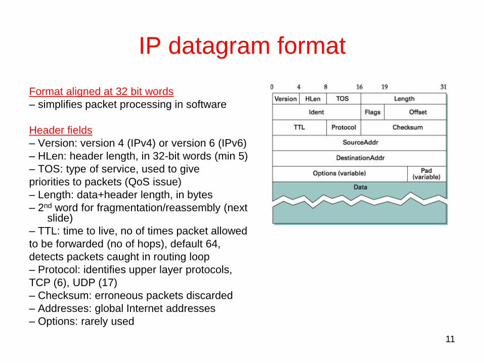
Format aligned at 32 bit words
– simplifies packet processing in software
Header fields
– Version: version 4 (IPv4) or version 6 (IPv6)
– HLen: header length, in 32-bit words (min 5)
– TOS: type of service, used to give
priorities to packets (QoS issue)
– Length: data+header length, in bytes
– 2nd word for fragmentation/reassembly (next slide)
– TTL: time to live, no of times packet allowed
to be forwarded (no of hops), default 64,
detects packets caught in routing loop
– Protocol: identifies upper layer protocols,
TCP (6), UDP (17)
– Checksum: erroneous packets discarded
– Addresses: global Internet addresses
– Options: rarely used

12
Fragmentation/reassembly
• Each network has an MTU (Maximum Transmission Unit)
– e.g., Ethernet 1500 bytes, PPP 532 bytes
• Strategy
– Fragment when necessary (MTU < datagram length)
– In general, try to avoid fragmentation: Hosts are encouraged to perform “path MTU discovery”
• Fragments are self-contained datagrams
– each fragment contains a common identifier in Ident field
– Flags (M-bit) and Offset used to guide fragmentation process
– Offset measured in 8 byte units
– Fragmented packet can be again re-fragmented
• Reassembly is performed only at destination host
• Reassembly does not try to recover lost fragments

13
Fragmentation/reassembly example
• Assume H5 wants to send a 1400 byte datagram to H8 (see slide 8): 1400 bytes + 20 bytes (IP header)
• MTU: 802.11 and Ethernet 1500 bytes, PPP 532 bytes
376 376

14
Example (continued)
(a) Unfragmented packet: H5R1R2
(b) Fragmented packets: R2R3H8
Can you think of a strategy
that will abuse fragmentation
to carry out a denial-of-service
attack?
How can one prevent such
an attack?

15
IP global addressing
• Properties
– globally unique, 32 bits
– hierarchical:
network part + host part
– address identifies interface
• end host has one interface
• router has many interfaces
– IP address domain name
• Original classful addressing
– class A, B and C networks
– defines different sized networks
– idea: small no of WANs, modest no of
campus networks, large no of LANs
• Dotted Decimal Notation
– 32 bit addresses represented as
groups of 8 bit integers
– e.g., 12.34.158.5
A : 1.0.0.0 to 127.255.255.255
B : 128.0.0.0 to 191.255.255.255
C : 192.0.0.0 to 223.255.255.255

16
Forwarding vs. routing
• Forwarding:
– Process of taking a packet from input interface,
looking at its destination address, consulting a
forwarding table, and sending the packet over an
output interface determined by that table
• Routing:
– Process by which forwarding tables are constructed
– Routing must create optimal or efficient paths that the
packets should follow

17
IP forwarding
• Preliminaries
– Every datagram contains destination’s address
– Every router has a forwarding table
– Each host has a default router configured
– Routers maintain forwarding tables with multiple entries (constructed via routing process)
– Forwarding table maps network number into next hop router number or local interface number
• Strategy
– A router receiving a packet checks destination network address of datagram and
– if directly connected to destination network, then forwards directly to host
– need to map IP address to physical LAN address (ARP)
– if not directly connected to destination network, then forwards to next hop router

18
IP forwarding example
H1H3: forwarding on the same network
H5H8: forwarding via R1 and R2
Router R2

19
Routers vs. bridges
Bridges are used for interconnecting LANs of the same type whereas routers interconnect networks of different (or the same) types
• Bridge (+/-)
+ bridge operation is simple, requires less processing
+ transparent (no configuration needed when new nodes added to LAN)
– restricted topology (forwarding determined by a spanning tree)
– LANs use a flat addressing space (no hierarchical network structure)
• Router (+/-)
+ arbitrary topologies, enables use of efficient routing algorithms for
distributing traffic (helps traffic management)
+ hierarchical addressing enables scalability:
• scalability requires minimization of address info stored in routers
• routing based on network numbers forwarding tables contain info on
all networks, not all nodes
– requires IP address configuration
– packet processing more demanding
• Summary: bridges do well in small (~ 100 hosts) networks while routers
are used in large networks (1000s of hosts)

20
Address translation
What to do when router/host notes that it is connected directly to the network where an arriving packet is destined ?
• Need to map IP addresses into physical LAN addresses
– destination host
– next hop router
• Techniques
– encode physical LAN address in host part of IP address not scalable! (not implemented)
– table-based (maintain IP address, PHY address pairs)
ARP

21
ARP details
• ARP (Address Resolution Protocol)
– utilizes LAN’s broadcast capabilities
– each node maintains table of IP to physical LAN address bindings
– broadcast request if address not in table
– target machine responds with its physical LAN address
• ARP request contains also source addresses (physical and IP)
– all “interested” parties can learn the source address
• Node (host/router) actions:
– table entries timeout in about 10 minutes
– if node already has an entry for source, refresh timer
– if node is the target, reply and update table with source info
– if node not target and does not have entry for the source, ignore source info

22
ARP packet format
– HardwareType: type of physical network (e.g., Ethernet)
– ProtocolType: type of higher layer protocol (e.g., IP)
– HLen & PLen: length of physical and upper layer addresses
– Operation: request or response
– Physical/IP addresses of Source and Target

23
Need for automatic configuration!
• IP addresses need to be reconfigurable
– Ethernet addresses hardwired onto the network adapter
– IP address consists of network and host part
– hosts can move between networks host gets new address in each
network
• Need for automated host configuration
– hosts need other configuration info, e.g., the default router
– configuration manually impossible (too much work and errors)
– Dynamic Host Configuration Protocol (DHCP)
• DHCP server
– at least one DHCP server for each administrative domain
– centralized repository for configuration info
– two operation modes:
administrator chooses host addresses and configures them to DHCP
DHCP manages the addresses by allocating addresses dynamically
from a pool of available addresses (more sophisticated)

24
DHCP operation
• Server discovery: host sends
DHCPDISCOVER msg to IP
broadcast address
(255.255.255.255)
• Msg broadcasted only on
same network
• If server on same network,
host receives its IP address
• If not, msg picked up by
DHCP relay agent
• Relay agent knows address of DHCP server, forwards the msg to DHCP
server and host receives its IP address
• Use of DHCP relay agent makes it possible to have fewer DHCP servers
(relay agent configuration simpler than DHCP server configuration)

25
Internet Control Message Protocol
• ICMP used for reporting errors in Internet
• Messages
– Echo (ping)
– Redirect (from router to source host if router knows of a better route to packet’s destination)
– Destination unreachable (protocol, port, or host)
– TTL exceeded (so datagrams don’t cycle forever)
– Checksum failed
– Reassembly failed
– Cannot fragment

26
Virtual private networks (VPN)
• Problem:
– group of isolated networks
– geographically distant from each other
– need to connect different networks together into a “private” network securely
– e.g., company with many branch offices
• Solution: VPN
• Methods
– Build a private network from leased lines (not shared)
– Create a virtual private network which is overlaid on top of public networks
• ATM and Frame Relay: Use virtual circuits
• IP: Use IP tunneling (usually coupled with secure IPsec)

27
VPN and IP tunneling
• Problem with IP:
- not possible to connect to Internet via router without the whole Internet
also knowing about your network.
• Tunneling
– virtual point-to-point link between two nodes separated by arbitrary no of
networks
– created at R1 by providing it with address of R2
– R1 encapsulates original packet in a new packet addressed to R2
– packet forwarded normally inside IP network
– R2 receives packet and strips off packet header and notices payload
contains an encapsulated packet addressed to some host inside network 2

28
Global Internet
Scalability Issues
IP “hides” hosts in address hierarchy, but...
• Inefficient use of address space
– class C network with 2 hosts (2/255 = 0.78% efficient)
– class B network with 256 hosts (256/65535 = 0.39%
efficient)
• Too many networks
– today's Internet has tens of thousands of networks
– routing tables do not scale
– route propagation protocols do not scale

29
Subnetting (1)
• Problem 1: Any network with more than 255
hosts, needs class B addresses, or should get
many class C addresses
• Problem 2: Each new network implies additional
entry in forwarding table large table
• Solution:
– Share one network number between several
networks. another level is added to
address/routing hierarchy : subnet

30
Subnetting (2)
• Makes most sense for large corporations or campuses
• Corporation networks share 1 network number
• Number of other networks within the corporation, using subnet masks
– E.g., a class B address, is shared among 8 networks, by using a 19-bit “subnet mask” (255.255.224.0 = 11111111 11111111 11100000 00000000)
– I.e., subnet addresses are defined by first 19 bits of the IP address. Host part now has a “subnet” part in it.
• Class B network address continues to be advertised to the rest of the Internet, subnetting only used “within campus” (i.e. Subnets visible only within site).

31
Subnetting (3)
• Another example: a class B address, is shared
among 256 networks, by using a 24-bit “subnet
mask” :
(255.255.255.0 = 11111111 11111111 111111111 00000000)

32
Subnet example
Forwarding table at R1:

33
Forwarding algorithm with subnetting
D = destination IP address
for each entry <SubnetNum, SubnetMask, NextHop>
D1 = SubnetMask & D
if D1 = SubnetNum
if NextHop is an interface
deliver datagram directly to destination
else
deliver datagram to NextHop (a router)
Q: Apply the algorithm when H1 is sending to H2 and H3.
Notes
• Would use a default router if nothing matches
• Not necessary for all ones in subnet mask to be contiguous
• Can put multiple subnets on one physical network
• Subnets not visible from the rest of the Internet

Subnetting Example
• Where does the router forward packets addressed to:
– 128.96.39.10 –> If0
– 128.96.40.12 –> R2
– 128.96.40.151 –> R4
– 192.4.153.17 –> R3
– 192.4.153.90 –> R4
34
Subnet Number Subnet Mask Next Hop
128.96.39.0 255.255.255.128 Interface 0
128.96.39.128 255.255.255.128 Interface 1
128.96.40.0 255.255.255.128 R2
192.4.153.0 255.255.255.192 R3
<default> R4
35
Supernetting (CIDR) (1)
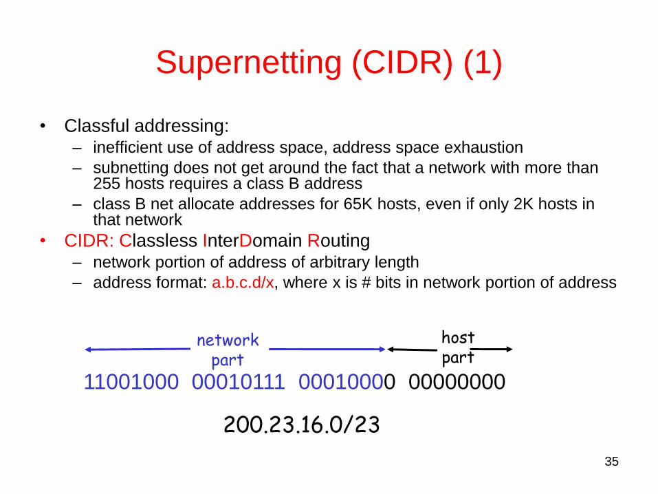
• Classful addressing: – inefficient use of address space, address space exhaustion
– subnetting does not get around the fact that a network with more than 255 hosts requires a class B address
– class B net allocate addresses for 65K hosts, even if only 2K hosts in that network
• CIDR: Classless InterDomain Routing – network portion of address of arbitrary length
– address format: a.b.c.d/x, where x is # bits in network portion of address
11001000 00010111 00010000 00000000
network part
host part
200.23.16.0/23

36
Supernetting (CIDR) (2)
• Assign block of contiguous network numbers to
near-by networks helps to aggregate routers less
entries in the forwarding tables
• Restrict block sizes to powers of 2
• E.g. Consider an Autonomous system with 16 class C
network numbers (192.4.16 to192.4.31) the top 20 bits
are same 20-bit network number (a single network
prefix) can be used in forwarding tables. Something
between class B and class C classless!

Route aggregation
37
To achieve scalability, you need
to reduce the amount of information
stored in routers
Hierarchical aggregation:
IP has a two-level hierarcy (network+host)

38
A simple example
• Suppose hosts had arbitrary addresses
– Then every router would need a lot of information
– …to know how to direct packets toward the host
host host host
LAN 1
... host host host
LAN 2
...
router router router WAN WAN
1.2.3.4 5.6.7.8 2.4.6.8 1.2.3.5 5.6.7.9 2.4.6.9
1.2.3.4
1.2.3.5
forwarding table
39
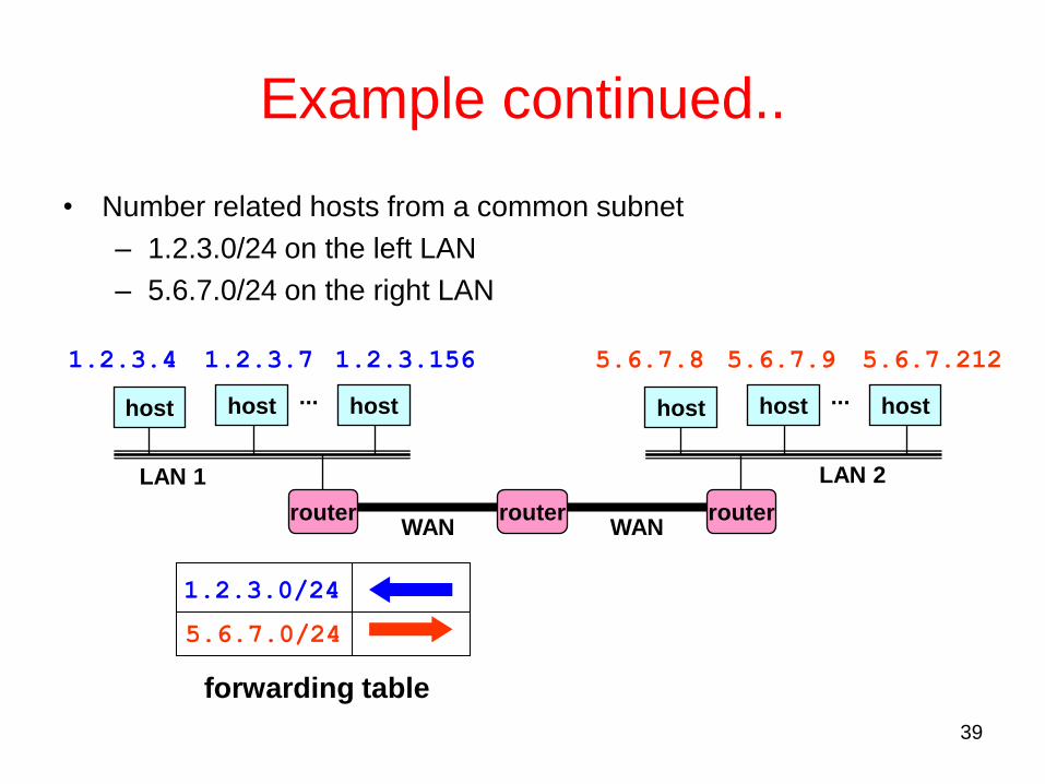
Example continued..
• Number related hosts from a common subnet
– 1.2.3.0/24 on the left LAN
– 5.6.7.0/24 on the right LAN
host host host
LAN 1
... host host host
LAN 2
...
router router router WAN WAN
1.2.3.4 1.2.3.7 1.2.3.156 5.6.7.8 5.6.7.9 5.6.7.212
1.2.3.0/24
5.6.7.0/24
forwarding table

40
Example continued.. • Easy to add a new host
• No need to update the routers
– E.g., adding a new host 5.6.7.213 on the right
– Doesn’t require adding a new forwarding entry
host host host
LAN 1
... host host host
LAN 2
...
router router router WAN WAN
1.2.3.4 1.2.3.7 1.2.3.156 5.6.7.8 5.6.7.9 5.6.7.212
1.2.3.0/24
5.6.7.0/24
forwarding table
host
5.6.7.213

41
Longest Prefix Match
• With CIDR, prefixes may be of any length and may overlap
• For example, suppose we have the following in the forwarding table at a router:
– 171.69 (a 16-bit prefix)
– 171.69.10 (a 24-bit prefix)
• A packet with destination address 171.69.10.5 matches both prefixes
• The rule is to choose the longest prefix to forward to
• Consider also 171.69.20.5. The longest match would be 171.69
• Efficient algorithms are required for finding the longest match in a forwarding table

CIDR Example • Suppose the router does the longest-prefix match. Where does the
router forward packets addressed (in hex) to:
– C4.5E.13.87 –> B
– C4.5E.22.09 –> A
– C3.41.80.02 –> E
– 5E.43.91.12 –> F
– C4.6D.31.2E –> C
– C4.6B.31.2E –> D
42
Net / Mask Length Next Hop
C4.50.0.0 / 12 A
C4.5E.10.0 / 20 B
C4.60.0.0 / 12 C
C4.68.0.0 / 14 D
80.0.0.0 / 1 E
40.0.0.0 / 2 F
00.0.0.0 / 2 G
43
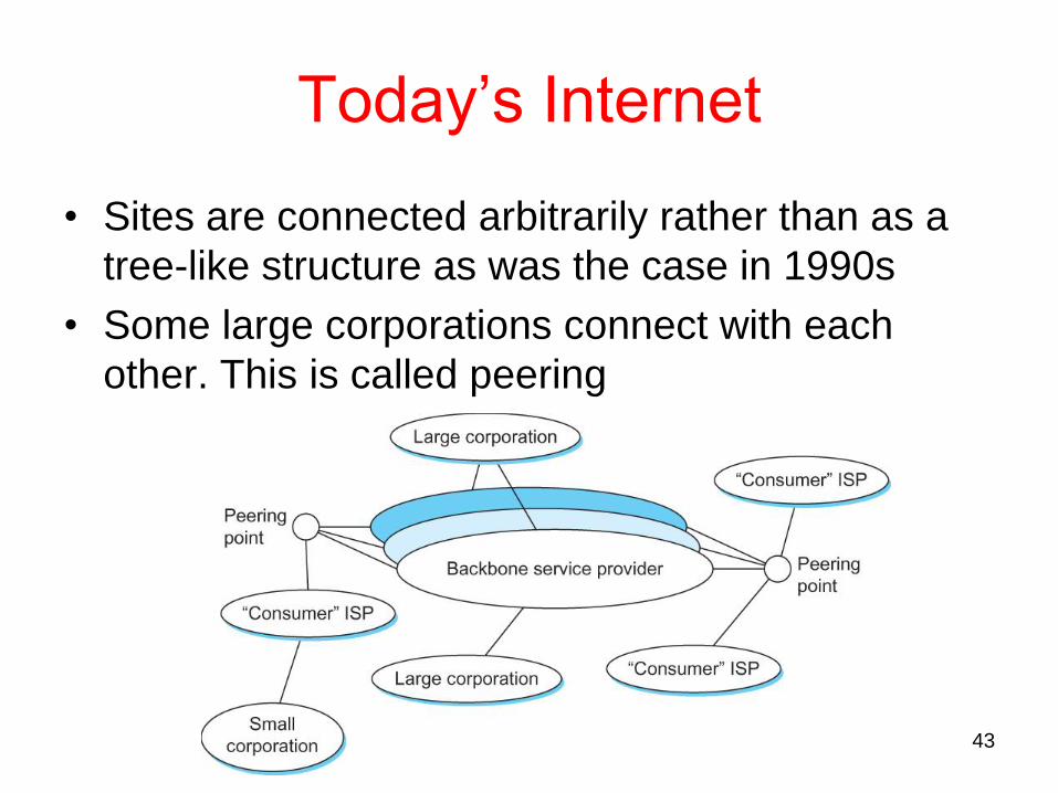
Today’s Internet
• Sites are connected arbitrarily rather than as a
tree-like structure as was the case in 1990s
• Some large corporations connect with each
other. This is called peering

44
Routing in the Internet (1)
• The Global Internet
consists of Autonomous
Systems (AS)
interconnected with
each other.
• AS:
– corresponds to an
administrative domain
– examples: University,
company, backbone
network
– Each AS is assigned
a 16-bit number

45
Routing in the Internet (2)
• We can classify ASs into three types: – Stub AS: small corporation: a single connection to
one other AS. only carry local traffic – Multihomed AS: large corporation: multiple
connections to other AS’s. (no transit, i.e. refuses to carry others traffic)
– Transit AS: provider, hooking many AS’s together – Q: Which ASes are Stub, Multihomed and Transit in
Slide 40?
• Two-level routing: – Intra-AS: administrator responsible for choice of
routing algorithm within network – Inter-AS: unique standard for inter-AS routing: BGP

46
Intra-AS, Inter-AS routing
• Most common Intra-AS routing protocols: - RIP: Routing Information Protocol - OSPF: Open Shortest Path First - IGRP: Interior Gateway Routing Protocol
AS2 ( OSPF
intra - AS
routing)
AS1 (RIP intra - AS
routing) BGP
AS3 ( OSPF intra - AS
routing)
BGP
R1 R2
R3
R4
R5
• Most common Inter-AS routing protocol is Border
Gateway Protocol (BGP)
- Leave “optimality” aside. Just find a loop-free path
- Thus only bothers with reachability

47
IPv6 (1)
Major Features
• 128-bit addresses
• Multicast
• Real-time service
• Authentication and security
• Autoconfiguration
• End-to-end fragmentation
• Protocol extensions

48
IPv6 (2)
IPv6 addresses
• Classless addressing/routing (similar to CIDR)
• Notation: x:x:x:x:x:x:x:x (x = 16-bit hex number)
– contiguous 0s are compressed: 47CD::A456:0124
– IPv6 compatible IPv4 address: ::128.42.1.87
• Address assignment
– provider-based
– geographic

49
IPv6 Header
• 40-byte “base” header
• Extension headers (fixed order, mostly fixed length)
– fragmentation
– source routing
– authentication and security
– other options