Embed Size (px)
Citation preview

Part Number: 1928• Part Title: Occup. Safety and Health Standards for Agriculture• Subpart: A• Subpart Title: General• StandardNumber: 1928
• Title: Table of Contents/Authority for 1928
PART 1928 -- OCCUPATIONAL SAFETY AND HEALTH STANDARDS FORAGRICULTURE
Subpart A -- General
Sec.1928.1 Purpose and scope.
Subpart B -- Applicability of Standards
1928.21 Applicable standards in 29 CFR Part 1910.
Subpart C -- Roll-Over Protective Structures
1928.51 Roll-over protective structures (ROPS) for tractors, used in agricultural tractors -test procedures and performance requirements.1928.52 Protective frames for wheel-type agricultural tractors -- test procedures andperformance requirements.1928.53 Protective enclosures for wheel-type agricultural tractors -- test procedures andperformance requirements.
APPENDICES TO SUBPART C
APPENDIX A - EMPLOYEE OPERATING INSTRUCTIONSAPPENDIX B - Figures C-1 through C-16
Subpart D -- Safety for Agricultural Equipment
1928.57 Guarding of farm field equipment, farmstead equipment, and cotton gins.
Subpart E-H -- [Reserved]
Subpart I -- General Environmental Controls
1928.110 Field Sanitation.
Subpart J-L [Reserved]

Subpart M -- Occupational Health
1928.1027 Cadmium
Authority: Sections 4, 6, and 8 of the Occupational Safety and Health Act of 1970 (29U.S.C. 653, 655, 657); and Secretary of Labor's Order No. 12-71 (36 FR 8754), 8-76 (41FR 25059), 9-83 (48 FR 35736), 1-90 (55 FR 9033), 6-96 (62 FR 111), 3-2000 (65 FR50017), 5-2002 (67 FR 65008), or 4-2010 (75 FR 55355), as applicable; and 29 CFR1911.
Section 1928.21 also issued under 49 U.S.C. 1801-1819 and 5 U.S.C. 533.
SOURCE: 40 FR 18257, Apr. 25, 1975, unless otherwise noted.[58 FR 21787, April 23, 1993; 59 FR 6170, Feb. 9, 1994; 59 FR 36695, July 19, 1994; 59FR 51672, Oct. 12, 1994; 61 FR 5507, Feb. 13, 1996; 61 FR 9227, March 7, 1996; 70 FR77003, Dec. 29, 2005; 71 FR 41145, July 20, 2006; 76 FR 33612, June 8, 2011]
Part Number: 1928• Part Title: Occup. Safety and Health Standards for Agriculture• Subpart: A• Subpart Title: General• StandardNumber: 1928 Subpart A
• Title: General
1928.1 This part contains occupational safety and health standards applicable toagricultural operations.
Part Number: 1928• Part Title: Occup. Safety and Health Standards for Agriculture• Subpart: B• Subpart Title: Applicability of Standards• StandardNumber: 1928 Subpart B
• Title: Applicability of Standards
1928.21(a)The following standards in part 1910 of this Chapter shall apply to agriculturaloperations:1928.21(a)(1)Temporary labor camps - 1910.142;1928.21(a)(2)Storage and handling of anhydrous ammonia - 1910.111(a) and (b);1928.21(a)(3)Logging Operations - 1910.266;1928.21(a)(4)
Slow-moving vehicles - 1910.145.1928.21(a)(5)Hazard communication - 1910.1200.1928.21(a)(6)Cadmium - 1910.1027.1928.21(a)(7)Retention of DOT markings, placards and labels - 1910.1201.1928.21(b)Except to the extent specified in paragraph (a) of this section, the standards contained inSubparts B through T and Subpart Z of part 1910 of this title do not apply to agriculturaloperations.(Section 1928.21 contains a collection of information which has been approved by theOffice of Management and Budget under OMB Control No. 1218-0072)[40 FR 18257, Apr. 25, 1975, as amended at 42 FR 38569, July 29, 1977; 52 FR 31886,Aug. 24, 1987; 59 FR 6184, Feb. 9, 1994; 59 FR 36700, July 19, 1994; 59 FR 51748,Oct. 12, 1994; 61 FR 5510, Feb. 13, 1996; 61 FR 9255, March 7, 1996]
Part Number: 1928• Part Title: Occup. Safety and Health Standards for Agriculture• Subpart: C• Subpart Title: Employee operating instruction• StandardNumber: 1928 Subpart C
• Title: Roll-Over Protective Structures• Appendix: A, B
1928.51(a)Definitions. As used in this subpart -
" Agricultural tractor" means a two or four-wheel drive type vehicle, or track vehicle, ofmore than 20 engine horsepower, designed to furnish the power to pull, carry, propel, ordrive implements that are designed for agriculture. All self-propelled implements areexcluded.
"Low profile tractor" means a wheeled tractor possessing the following characteristics:1928.51(a)(1)The front wheel spacing is equal to the rear wheel spacing, as measured from thecenterline of each right wheel to the centerline of the corresponding left wheel.1928.51(a)(2)The clearance from the bottom of the tractor chassis to the ground does not exceed 18inches.1928.51(a)(3)The highest point of the hood does not exceed 60 inches, and1928.51(a)(4)The tractor is designed so that the operator straddles the transmission when seated.

"Tractor weight" includes the protective frame or enclosure, all fuels, and othercomponents required for normal use of the tractor. Ballast shall be added as necessary toachieve a minimum total weight of 110 lb. (50.0 kg.) per maximum power take-off horsepower at the rated engine speed or the maximum, gross vehicle weight specified by themanufacturer, whichever is the greatest. From end weight shall be at least 25 percent ofthe tractor test weight. In case power take-off horsepower is not available, 95 percent ofnet engine flywheel horsepower shall be used.1928.51(b)General requirements. Agricultural tractors manufactured after October 25, 1976, shallmeet the following requirements:1928.51(b)(1)Roll-over protective structures (ROPS). ROPS shall be provided by the employer foreach tractor operated by an employee. Except as provided in paragraph (b)(5) of thissection, a ROPS used on wheel-type tractors shall meet the test and performancerequirements of 29 CFR 1928.52, 1928.53, or 1926.1002 as appropriate. A ROPS used ontrack-type tractors shall meet the test and performance requirements of 29 CFR1926.1001.1928.51(b)(2)Seatbelts.1928.51(b)(2)(i)Where ROPS are required by this section, the employer shall:1928.51(b)(2)(i)(A)Provide each tractor with a seatbelt which meets the requirements of this paragraph;1928.51(b)(2)(i)(B)Ensure that each employee tightens the seatbelt sufficiently to confine the employee tothe protected area provided by the ROPS.1928.51(b)(2)(ii)Each seatbelt shall meet the requirements set forth in Society of Automotive EngineerStandard SAE J4C, 1965 Motor Vehicle Seat Belt Assemblies(2), except as notedhereafter:
____________ Footnote(2) Copies may be obtained from the Society of AutomotiveEngineers, 400 Commonwealth Drive, Warrendale, Pa. 15096.1928.51(b)(2)(ii)(A)Where a suspended seat is used, the seatbelt shall be fastened to the movable portion ofthe seat to accommodate a ride motion of the operator.1928.51(b)(2)(ii)(B)The seatbelt anchorage shall be capable of withstanding a static tensile load of 1,000pounds (453.6 kg) at 45 degrees to the horizontal equally divided between theanchorages. The seat mounting shall be capable of withstanding this load plus a loadequal to four times the weight of all applicable sear components applied at 45 degrees tothe horizontal in a forward and upward direction. In addition, the seat mounting shall becapable of withstanding a 500 pound (226.8 kg) belt load plus two times the weight of allapplicable seat components both applied at 45 degrees to the horizontal in and upwardand rearward direction. Floor and seat deformation is acceptable provided there is notstructural failure or release of the seat adjusted mechanism or other locking device.

1928.51(b)(2)(ii)(C)The seatbelt webbing material shall have a resistance to acids, alkalies, mildew, aging,moisture, and sunlight equal to or better than that of untreated polyester fiber.1928.51(b)(3)Protection from spillage. Batteries, fuel tanks, oil reservoirs, and coolant systems shall beconstructed and located or sealed to assure that spillage will not occur which may comein contact with the operator in the event of an upset.1928.51(b)(4)Protection from sharp surfaces. All sharp edges and corners at the operator's station shallbe designed to minimize operator injury in the event of an upset.1928.51(b)(5)Exempted uses. Paragraphs (b)(1) and (b)(2) of this section do not apply to the followinguses:1928.51(b)(5)(i)"Low profile" tractors while they are used in orchards, vineyards or hop yards where thevertical clearance requirements would substantially interfere with normal operations, andwhile their use is incidental to the work performed therein.1928.51(b)(5)(ii)"Low profile" tractors while used inside a farm building or greenhouse in which thevertical clearance is insufficient to allow a ROPS equipped tractor to operate, and whiletheir use is incidental to the work performed therein.1928.51(b)(5)(iii)Tractors while used with mounted equipment which is incompatible with ROPS (e.g.corn pickers, cotton strippers, vegetable pickers and fruit harvesters).1928.51(b)(6)Remounting. Where ROPS are removed for any reason, they shall be remounted so as tomeet the requirements of this paragraph.1928.51(c)Labeling. Each ROPS shall have a label, permanently affixed to the structure, whichstates:1928.51(c)(1)Manufacturer's or fabricator's name and address;1928.51(c)(2)ROPS model number, if any;1928.51(c)(3)Tractor makes, models, or series numbers that the structure is designed to fit; and1928.51(c)(4)That the ROPS model was tested in accordance with the requirements of this subpart.1928.51(d)Operating instructions. Every employee who operates an agricultural tractor shall beinformed of the operating practices contained in Appendix A of this part and of any otherpractices dictated by the work environment. Such information shall be provided at thetime of initial assignment and at least annually thereafter.
[61 FR 9227, March 7, 1996; 70 FR 77003, Dec. 29, 2005]

1928.52(a)Purpose. The purpose of this section is to establish the test and performance requirementsfor a protective frame designed for wheel-type agricultural tractors to minimize thefrequency and severity of operator injury resulting from accidental upsets. Generalrequirements for the protection of operators are specified in 29 CFR 1928.51.1928.52(b)Types of tests. All protective frames for wheel-type agricultural tractors shall be of amodel that has been tested as follows:1928.52(b)(1)Laboratory test. A laboratory energy-absorption test, either static or dynamic, underrepeatable and controlled loading, to permit analysis of the protective frame forcompliance with the performance requirements of this standard.1928.52(b)(2)Field-upset test. A field-upset test under controlled conditions, both to the side and rear,to verify the effectiveness of the protective system under actual dynamic conditions. Suchtesting may be omitted when:1928.52(b)(2)(i)The analysis of the protective-frame static-energy absorption test results indicates thatboth FERis and FERir (as defined in paragraph (d)(2)(ii) of this section) exceed 1.15; or1928.52(b)(2)(ii)The analysis of the protective-frame dynamic-energy absorption test results indicates thatthe frame can withstand an impact of 15 percent greater than the impact it is required towithstand for the tractor weight as shown in Figure C-7.1928.52(c)Descriptions.1928.52(c)(1)Protective frame. A protective frame is a structure comprised of uprights mounted to thetractor, extending above the operator's seat. A typical two-post frame is shown in FigureC-1.1928.52(c)(2)Overhead weather shield. When an overhead weather shield is available for attachmentto the protective frame, it may be in place during tests provided it does not contribute tothe strength of the protective frame.1928.52(c)(3)Overhead falling object protection. When an overhead falling-object protection device isavailable for attachment to the protective frame, it may be in place during tests providedit does not contribute to the strength of the protective frame.1928.52(d)Test procedures.1928.52(d)(1)General.1928.52(d)(1)(i)The tractor weight used shall be that of the heaviest tractor model on which the protectiveframe is to be used.1928.52(d)(1)(ii)

Each test required under this section shall be performed on a new protective frame.Mounting connections of the same design shall be used during each such test.1928.52(d)(1)(iii)Instantaneous deflection shall be measured and recorded for each segment of the test; seeparagraph (e)(1)(i) of this section for permissible deflections.1928.52(d)(1)(iv)The seat-reference point ("SRP") in Figure C-3 is that point where the vertical line that istangent to the most forward point at the longitudinal seat centerline of the seat back, andthe horizontal line that is tangent to the highest point of the seat cushion, intersect in thelongitudinal seat section. The seat-reference point shall be determined with the seatunloaded and adjusted to the highest and most rearward position provided for seatedoperation of the tractor.1928.52(d)(1)(v)When the centerline of the seat is off the longitudinal center, the frame loading shall beon the side with the least space between the centerline of seat and the protective frame.1928.52(d)(1)(vi)Low-temperature characteristics of the protective frame or its material shall bedemonstrated as specified in paragraph (e)(1)(ii) of this section.1928.52(d)(1)(vii)Rear input energy tests (static, dynamic, or field-upset) need not be performed on framesmounted to tractors having four driven wheels and more than one-half their unballastedweight on the front wheels.1928.52(d)(1)(viii)Accuracy table:Measurements AccuracyDeflection of the frame, in. (mm) ±5 percent of the deflection measured.Vertical weight, lb (kg) ±5 percent of the weight measured.Force applied to the frame, pounds force(newtons).
±5 percent of the force measured.
Dimensions of the critical zone, in. (mm). ±0.5 in. (12.5 mm).1928.52(d)(2)Static test procedure.1928.52(d)(2)(i)The following test conditions shall be met:1928.52(d)(2)(i)(A)The laboratory mounting base shall be the tractor chassis for which the protective frameis designed, or its equivalent;1928.52(d)(2)(i)(B)The protective frame shall be instrumented with the necessary equipment to obtain therequired load-deflection data at the locations and directions specified in Figures C-2 andC-3; and1928.52(d)(2)(i)(C)When the protective frame is of a one- or two-upright design, mounting connections shallbe instrumented with the necessary equipment to record the required force to be used inparagraph (d)(2)(iii)(E) and (J) of this section. Instrumentation shall be placed onmounting connections before installation load is applied.
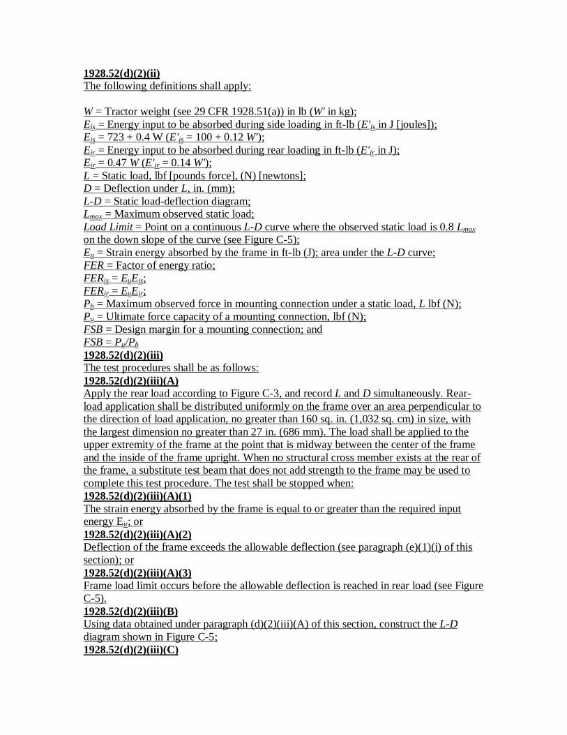
1928.52(d)(2)(ii)The following definitions shall apply:
W = Tractor weight (see 29 CFR 1928.51(a)) in lb (W' in kg);Eis = Energy input to be absorbed during side loading in ft-lb (E'is in J [joules]);Eis = 723 + 0.4 W (E'is = 100 + 0.12 W');Eir = Energy input to be absorbed during rear loading in ft-lb (E'ir in J);Eir = 0.47 W (E'ir = 0.14 W');L = Static load, lbf [pounds force], (N) [newtons];D = Deflection under L, in. (mm);L-D = Static load-deflection diagram;Lmax = Maximum observed static load;Load Limit = Point on a continuous L-D curve where the observed static load is 0.8 Lmaxon the down slope of the curve (see Figure C-5);Eu = Strain energy absorbed by the frame in ft-lb (J); area under the L-D curve;FER = Factor of energy ratio;FERis = EuEis;FERir = EuEir;Pb = Maximum observed force in mounting connection under a static load, L lbf (N);Pu = Ultimate force capacity of a mounting connection, lbf (N);FSB = Design margin for a mounting connection; andFSB = Pu/Pb1928.52(d)(2)(iii)The test procedures shall be as follows:1928.52(d)(2)(iii)(A)Apply the rear load according to Figure C-3, and record L and D simultaneously. Rear-load application shall be distributed uniformly on the frame over an area perpendicular tothe direction of load application, no greater than 160 sq. in. (1,032 sq. cm) in size, withthe largest dimension no greater than 27 in. (686 mm). The load shall be applied to theupper extremity of the frame at the point that is midway between the center of the frameand the inside of the frame upright. When no structural cross member exists at the rear ofthe frame, a substitute test beam that does not add strength to the frame may be used tocomplete this test procedure. The test shall be stopped when:1928.52(d)(2)(iii)(A)(1)The strain energy absorbed by the frame is equal to or greater than the required inputenergy Eir; or1928.52(d)(2)(iii)(A)(2)Deflection of the frame exceeds the allowable deflection (see paragraph (e)(1)(i) of thissection); or1928.52(d)(2)(iii)(A)(3)Frame load limit occurs before the allowable deflection is reached in rear load (see FigureC-5).1928.52(d)(2)(iii)(B)Using data obtained under paragraph (d)(2)(iii)(A) of this section, construct the L-Ddiagram shown in Figure C-5;1928.52(d)(2)(iii)(C)

Calculate Eir;1928.52(d)(2)(iii)(D)Calculate FERir;1928.52(d)(2)(iii)(E)Calculate FSB as required by paragraph (d)(2)(i)(C) of this section;1928.52(d)(2)(iii)(F)Apply the side-load tests on the same frame, and record L and D simultaneously. Side-load application shall be at the upper extremity of the frame at a 90º angle to thecenterline of the vehicle. The side load shall be applied to the longitudinal side farthestfrom the point of rear-load application. Apply side load L as shown in Figure C-2. Thetest shall be stopped when:1928.52(d)(2)(iii)(F)(1)The strain energy absorbed by the frame is equal to or greater than the required inputenergy Eis; or1928.52(d)(2)(iii)(F)(2)Deflection of the frame exceeds the allowable deflection (see paragraph (e)(1)(i) of thissection); or1928.52(d)(2)(iii)(F)(3)Frame load limit occurs before the allowable deflection is reached in side load (seeFigure C-5).1928.52(d)(2)(iii)(G)Using data obtained in paragraph (d)(2)(iii)(F) of this section, construct the L-D diagramas shown in Figure C-5;1928.52(d)(2)(iii)(H)Calculate Eis;1928.52(d)(2)(iii)(I)Calculate FERis; and1928.52(d)(2)(iii)(J)Calculate FSB as required by paragraph (d)(2)(i)(C) of this section.1928.52(d)(3)Dynamic test procedure.1928.52(d)(3)(i)The following test conditions shall be met:1928.52(d)(3)(i)(A)The protective frame and tractor shall be tested at the weight defined by 29 CFR1928.51(a);1928.52(d)(3)(i)(B)The dynamic loading shall be accomplished by using a 4,410-lb (2,000-kg) weight actingas a pendulum. The impact face of the weight shall be 27 ± 1 in. by 27 ± 1 in. (686 ± 25mm by 686 ± 25 mm), and shall be constructed so that its center of gravity is within 1.0in. (25.4 mm) of its geometric center. The weight shall be suspended from a pivot point18 to 22 ft (5.5 to 6.7 m) above the point of impact on the frame, and shall beconveniently and safely adjustable for height (see Figure C-6);1928.52(d)(3)(i)(C)For each phase of testing, the tractor shall be restrained from moving when the dynamicload is applied. The restraining members shall have strength no less than, and elasticity

no greater than, that of 0.50-in. (12.7-mm) steel cable. Points of attachment for therestraining members shall be located an appropriate distance behind the rear axle and infront of the front axle to provide a 15º to 30º angle between a restraining cable and thehorizontal. For impact from the rear, the restraining cables shall be located in the plane inwhich the center of gravity of the pendulum will swing, or alternatively, two sets ofsymmetrically located cables may be used at lateral locations on the tractor. For impactfrom the side, restraining cables shall be used as shown in Figures C-8 and C-9;1928.52(d)(3)(i)(D)The front and rear wheel-tread settings, when adjustable, shall be at the position nearestto halfway between the minimum and maximum settings obtainable on the vehicle. Whenonly two settings are obtainable, the minimum setting shall be used. The tires shall haveno liquid ballast, and shall be inflated to the maximum operating pressure recommendedby the manufacturer. With the specified tire inflation, the restraining cable shall betightened to provide tire deflection of 6 to 8 percent of the nominal tire-section width.After the vehicle is restrained properly, a wooden beam no less than 6-in. x 6-in. (150-mm x 150-mm) in cross section shall be driven tightly against the appropriate wheels andclamped. For the test to the side, an additional wooden beam shall be placed as a propagainst the wheel nearest to the operator's station, and shall be secured to the base so thatit is held tightly against the wheel rim during impact. The length of this beam shall bechosen so that it is at an angle of 25º to 40º to the horizontal when it is positioned againstthe wheel rim. It shall have a length 20 to 25 times its depth, and a width two to threetimes its depth (see Figures C-8 and C-9);1928.52(d)(3)(i)(E)Means shall be provided for indicating the maximum instantaneous deflection along theline of impact. A simple friction device is illustrated in Figure C-4;1928.52(d)(3)(i)(F)No repairs or adjustments shall be made during the test; and1928.52(d)(3)(i)(G)When any cables, props, or blocking shift or break during the test, the test shall berepeated.1928.52(d)(3)(ii)H = Vertical height of the center of gravity of a 4,410-lb (2,000-kg) weight in in. (H' inmm). The weight shall be pulled back so that the height of its center of gravity above thepoint of impact is: H = 4.92 + 0.00190 W (H' = 125 ± 0.170 W') (see Figure C-7).1928.52(d)(3)(iii)The test procedures shall be as follows:1928.52(d)(3)(iii)(A)The frame shall be evaluated by imposing dynamic loading from the rear, followed by aload to the side on the same frame. The pendulum swinging from the height determinedby paragraph (d)(3)(ii) of this section shall be used to impose the dynamic load. Theposition of the pendulum shall be so selected that the initial point of impact on the frameis in line with the arc of travel of the center of gravity of the pendulum. When a quick-release mechanism is used, it shall not influence the attitude of the block;1928.52(d)(3)(iii)(B)Impact at rear. The tractor shall be restrained properly according to paragraphs(d)(3)(i)(C) and (d)(3)(i)(D) of this section. The tractor shall be positioned with respect to
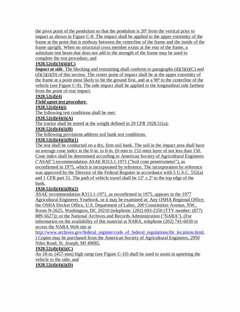
the pivot point of the pendulum so that the pendulum is 20º from the vertical prior toimpact as shown in Figure C-8. The impact shall be applied to the upper extremity of theframe at the point that is midway between the centerline of the frame and the inside of theframe upright. When no structural cross member exists at the rear of the frame, asubstitute test beam that does not add to the strength of the frame may be used tocomplete the test procedure; and1928.52(d)(3)(iii)(C)Impact at side. The blocking and restraining shall conform to paragraphs (d)(3)(i)(C) and(d)(3)(i)(D) of this section. The center point of impact shall be at the upper extremity ofthe frame at a point most likely to hit the ground first, and at a 90º to the centerline of thevehicle (see Figure C-9). The side impact shall be applied to the longitudinal side farthestfrom the point of rear impact.1928.52(d)(4)Field-upset test procedure.1928.52(d)(4)(i)The following test conditions shall be met:1928.52(d)(4)(i)(A)The tractor shall be tested at the weight defined in 29 CFR 1928.51(a);1928.52(d)(4)(i)(B)The following provisions address soil bank test conditions.1928.52(d)(4)(i)(B)(1)The test shall be conducted on a dry, firm soil bank. The soil in the impact area shall havean average cone index in the 0-in. to 6-in. (0-mm to 152-mm) layer of not less than 150.Cone index shall be determined according to American Society of Agricultural Engineers("ASAE") recommendation ASAE R313.1-1971 ("Soil cone penetrometer"), asreconfirmed in 1975, which is incorporated by reference. The incorporation by referencewas approved by the Director of the Federal Register in accordance with 5 U.S.C. 552(a)and 1 CFR part 51. The path of vehicle travel shall be 12º ± 2º to the top edge of thebank.1928.52(d)(4)(i)(B)(2)ASAE recommendation R313.1-1971, as reconfirmed in 1975, appears in the 1977Agricultural Engineers Yearbook, or it may be examined at: Any OSHA Regional Office;the OSHA Docket Office, U.S. Department of Labor, 200 Constitution Avenue, NW.,Room N-2625, Washington, DC 20210 (telephone: (202) 693-2350 (TTY number: (877)889-5627)); or the National Archives and Records Administration ("NARA"). (Forinformation on the availability of this material at NARA, telephone (202) 741-6030 oraccess the NARA Web site athttp://www.archives.gov/federal_register/code_of_federal_regulations/ibr_locations.html.) Copies may be purchased from the American Society of Agricultural Engineers, 2950Niles Road, St. Joseph, MI 49085.1928.52(d)(4)(i)(C)An 18-in. (457-mm) high ramp (see Figure C-10) shall be used to assist in upsetting thevehicle to the side; and1928.52(d)(4)(i)(D)

The front and rear wheel-tread settings, when adjustable, shall be at the position nearestto halfway between the minimum and maximum settings obtainable on the vehicle. Whenonly two settings are obtainable, the minimum setting shall be used.1928.52(d)(4)(ii)Field upsets shall be induced to the rear and side as follows:1928.52(d)(4)(ii)(A)Rear upset shall be induced by engine power, with the tractor operating in gear to obtain3 to 5 mph (4.8 to 8.0 kph) at maximum governed engine rpm by driving forward directlyup a minimum slope of 60º ± 5º as shown in Figure C-11, or by an alternative equivalentmeans. The engine clutch may be used to aid in inducing the upset; and1928.52(d)(4)(ii)(B)To induce side upset, the tractor shall be driven under its own power along the specifiedpath of travel at a minimum speed of 10 mph (16 kph), or at maximum vehicle speedwhen under 10 mph (16 kph), and over the ramp as described in paragraph (d)(4)(i)(C) ofthis section.1928.52(e)Performance requirements.1928.52(e)(1)General requirements.1928.52(e)(1)(i)The frame, overhead weather shield, fenders, or other parts in the operator area may bedeformed in these tests, but shall not shatter or leave sharp edges exposed to the operator,or encroach on the dimensions shown in Figures C-2 and C-3, and specified as follows:
d = 2 in. (51 mm) inside of the frame upright to the vertical centerline of the seat;e = 30 in. (762 mm) at the longitudinal centerline;f = Not greater than 4 in. (102 mm) to the rear edge of the crossbar, measured forward ofthe seat-reference point ("SRP");g = 24 in. (610 mm) minimum; andm = Not greater than 12 in. (305 mm), measured from the seat-reference point to theforward edge of the crossbar.1928.52(e)(1)(ii)The protective structure and connecting fasteners must pass the static or dynamic testsdescribed in paragraphs (d)(2), (d)(3), or (d)(4) of this section at a metal temperature of 0ºF (-18 ºC) or below, or exhibit Charpy V-notch impact strengths as follows:
10-mm x 10-mm (0.394-in. x 0.394-in.) specimen: 8.0 ft-lb (10.8 J) at -20 ºF (-30 ºC);10-mm x 7.5-mm (0.394-in. x 0.296-in.) specimen: 7.0 ft-lb (9.5 J) at -20 ºF (-30 ºC);10-mm x 5-mm (0.394-in. x 0.197-in.) specimen: 5.5 ft-lb (7.5 J) at -20 ºF (-30 ºC); or10-mm x 2.5-mm (0.394-in. x 0.098-in.) specimen: 4.0 ft-lb (5.5 J) at -20 ºF (-30 ºC).
Specimens shall be longitudinal and taken from flat stock, tubular, or structural sectionsbefore forming or welding for use in the frame. Specimens from tubular or structuralsections shall be taken from the middle of the side of greatest dimension, not to includewelds.1928.52(e)(2)

Static test-performance requirements. In addition to meeting the requirements ofparagraph (e)(1) of this section for both side and rear loads, FERis and FERir, shall begreater than 1.0, and when the ROPS contains one or two upright frames only, FSB shallbe greater than 1.3.1928.52(e)(3)Dynamic test-performance requirements. The structural requirements shall be met whenthe dimensions in paragraph (e)(1) of this section are used in both side and rear loads.1928.52(e)(4)Field-upset test performance requirements. The requirements of paragraph (e)(1) of thissection shall be met for both side and rear upsets.
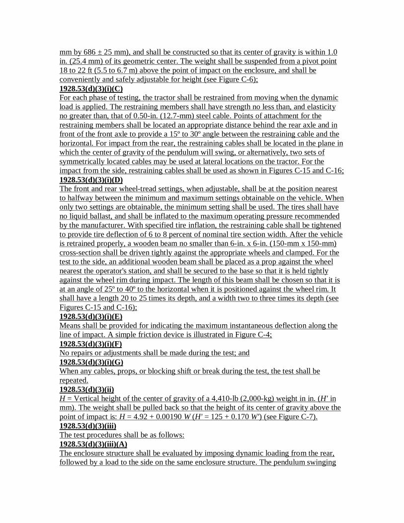
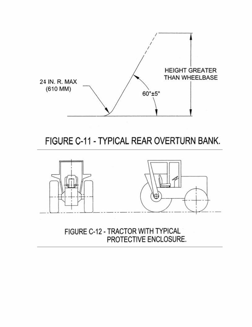
1928.53(a)Purpose. The purpose of this section is to establish the test and performance requirementsfor a protective enclosure designed for wheel-type agricultural tractors to minimize thefrequency and severity of operator injury resulting from accidental upset. Generalrequirements for the protection of operators are specified in 29 CFR 1928.51.1928.53(b)Types of tests. All protective enclosures for wheel-type agricultural tractors shall be of amodel that has been tested as follows:1928.53(b)(1)Laboratory test. A laboratory energy-absorption test, either static or dynamic, underrepeatable and controlled loading, to permit analysis of the protective enclosure forcompliance with the performance requirements of this standard; and1928.53(b)(2)Field-upset test. A field-upset test under controlled conditions, both to the side and rear,to verify the effectiveness of the protective system under actual dynamic conditions. Thistest may be omitted when:1928.53(b)(2)(i)The analysis of the protective-frame static-energy absorption test results indicates thatboth FERis and FERir (as defined in paragraph (d)(2)(ii) of this section) exceed 1.15; or1928.53(b)(2)(ii)The analysis of the protective-frame dynamic-energy absorption test results indicates thatthe frame can withstand an impact of 15 percent greater than the impact it is required towithstand for the tractor weight as shown in Figure C-7.1928.53(c)Descriptions. A protective enclosure is a structure comprising a frame and/or enclosuremounted to the tractor. A typical enclosure is shown in Figure C-12.1928.53(d)Test procedures.1928.53(d)(1)General.1928.53(d)(1)(i)The tractor weight used shall be that of the heaviest tractor model on which the protectiveenclosure is to be used.1928.53(d)(1)(ii)

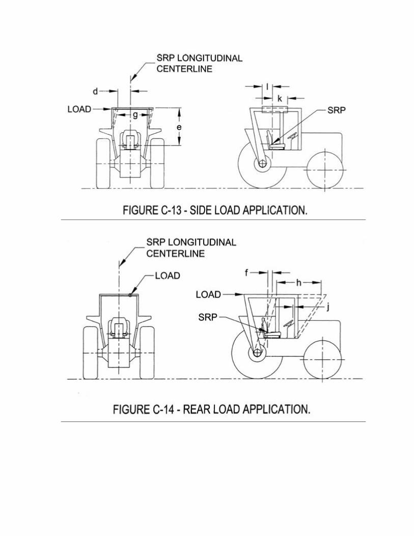
Each test required under this section shall be performed on a protective enclosure withnew structural members. Mounting connections of the same design shall be used duringeach test.1928.53(d)(1)(iii)Instantaneous deflection shall be measured and recorded for each segment of the test; seeparagraph (e)(1)(i) of this section for permissible deflections.1928.53(d)(1)(iv)The seat-reference point ("SRP") in Figure C-14 is that point where the vertical line thatis tangent to the most forward point at the longitudinal seat centerline of the seat back,and the horizontal line that is tangent to the highest point of the seat cushion, intersect inthe longitudinal seat section. The seat-reference point shall be determined with the seatunloaded and adjusted to the highest and most rearward position provided for seatedoperations of the tractor.1928.53(d)(1)(v)When the centerline of the seat is off the longitudinal center, the protective-enclosureloading shall be on the side with least space between the centerline of the seat and theprotective enclosure.1928.53(d)(1)(vi)Low-temperature characteristics of the protective enclosure or its material shall bedemonstrated as specified in paragraph (e)(1)(ii) of this section.1928.53(d)(1)(vii)Rear input energy tests (static, dynamic, or field-upset) need not be performed onenclosures mounted to tractors having four driven wheels and more than one-half theirunballasted weight on the front wheels.1928.53(d)(1)(viii)Accuracy table:Measurements AccuracyDeflection of the enclosure, in. (mm) ±5 percent of the deflection measured.Vertical weight, pounds (kg) ±5 percent of the weight measured.Force applied to the enclosure, poundsforce (newtons).
±5 percent of the force measured.
Dimensions of the critical zone, in. (mm). ±0.5 in. (12.5 mm).1928.53(d)(1)(ix)When movable or normally removable portions of the enclosure add to structuralstrength, they shall be placed in configurations that contribute least to structural strengthduring the test.1928.53(d)(2)Static test procedure.1928.53(d)(2)(i)The following test conditions shall be met:1928.53(d)(2)(i)(A)The laboratory mounting base shall be the tractor chassis for which the protectiveenclosure is designed, or its equivalent; and1928.53(d)(2)(i)(B)

The protective enclosure shall be instrumented with the necessary equipment to obtainthe required load-deflection data at the locations and directions specified in Figures C-13and C-14.1928.53(d)(2)(ii)The following definitions shall apply:
W = Tractor weight (see 29 CFR 1928.51(a)) in lb (W' in kg);Eis = Energy input to be absorbed during side loading in ft-lb (E'is in J [joules]);Eis = 723 + 0.4 W (E'is = 100 + 0.12 W');Eir = Energy input to be absorbed during rear loading in ft-lb (E'ir in J);Eir = 0.47 W (E'ir = 0.14 W');L = Static load, lbf [pounds force], (N) [newtons];D = Deflection under L, in. (mm);L-D = Static load-deflection diagram;Lmax = Maximum observed static load;Load Limit = Point on a continuous L-D curve where the observed static load is 0.8 Lmaxon the down slope of the curve (see Figure C-5);Eu = Strain energy absorbed by by the protective enclosure in ft-lbs (J); area under the L-D curve;FER = Factor of energy ratio;FERis = Eu/Eis; andFERir = Eu/Eir.1928.53(d)(2)(iii)The test procedures shall be as follows:1928.53(d)(2)(iii)(A)When the protective-frame structures are not an integral part of the enclosure, thedirection and point of load application for both side and rear shall be the same asspecified in 29 CFR 1928.52(d)(2);1928.53(d)(2)(iii)(B)When the protective-frame structures are an integral part of the enclosure, apply the rearload according to Figure C-14, and record L and D simultaneously. Rear-load applicationshall be distributed uniformly on the frame structure over an area perpendicular to theload application, no greater than 160 sq. in. (1,032 sq. cm) in size, with the largestdimension no greater than 27 in. (686 mm). The load shall be applied to the upperextremity of the structure at the point that is midway between the centerline of theprotective enclosure and the inside of the protective structure. When no structural crossmember exists at the rear of the enclosure, a substitute test beam that does not addstrength to the structure may be used to complete this test procedure. The test shall bestopped when:1928.53(d)(2)(iii)(B)(1)The strain energy absorbed by the structure is equal to or greater than the required inputenergy Eir; or1928.53(d)(2)(iii)(B)(2)Deflection of the structure exceeds the allowable deflection (see paragraph (e)(1)(i) ofthis section); or1928.53(d)(2)(iii)(B)(3)

The structure load limit occurs before the allowable deflection is reached in rear load (seeFigure C-5);1928.53(d)(2)(iii)(C)Using data obtained in paragraph (d)(2)(iii)(B) of this section, construct the L-D diagramfor rear loads as shown in Figure C-5;1928.53(d)(2)(iii)(D)Calculate Eir;1928.53(d)(2)(iii)(E)Calculate FERir;1928.53(d)(2)(iii)(F)When the protective-frame structures are an integral part of the enclosure, apply the sideload according to Figure C-13, and record L and D simultaneously. Static side-loadapplication shall be distributed uniformly on the frame over an area perpendicular to thedirection of load application, and no greater than 160 sq. in. (1,032 sq. cm) in size, withthe largest dimension no greater than 27 in. (686 mm). Side-load application shall be at a90º angle to the centerline of the vehicle. The center of the side-load application shall belocated between point k, 24 in. (610 mm) forward of the seat-reference point, and point l,12 in. (305 mm) rearward of the seat-reference point, to best use the structural strength(see Figure C-13). This side load shall be applied to the longitudinal side farthest fromthe point of rear-load application. The test shall be stopped when:1928.53(d)(2)(iii)(F)(1)The strain energy absorbed by the structure is equal to or greater than the required inputenergy Eis; or1928.53(d)(2)(iii)(F)(2)Deflection of the structure exceeds the allowable deflection (see paragraph (e)(1)(i) ofthis section); or1928.53(d)(2)(iii)(F)(3)The structure load limit occurs before the allowable deflection is reached in side load (seeFigure C-5).1928.53(d)(2)(iii)(G)Using data obtained in paragraph (d)(2)(iii)(F) of this section, construct the L-D diagramfor the side load as shown in Figure C-5;1928.53(d)(2)(iii)(H)Calculate FERis;1928.53(d)(2)(iii)(I)Calculate FERir.1928.53(d)(3)Dynamic test procedure.1928.53(d)(3)(i)The following test conditions shall be met:1928.53(d)(3)(i)(A)The protective enclosure and tractor shall be tested at the weight defined by 29 CFR1928.51(a);1928.53(d)(3)(i)(B)The dynamic loading shall be accomplished by using a 4,410-lb (2,000-kg) weight actingas a pendulum. The impact face of the weight shall be 27 ± 1 in. by 27 ± 1 in. (686 ± 25
mm by 686 ± 25 mm), and shall be constructed so that its center of gravity is within 1.0in. (25.4 mm) of its geometric center. The weight shall be suspended from a pivot point18 to 22 ft (5.5 to 6.7 m) above the point of impact on the enclosure, and shall beconveniently and safely adjustable for height (see Figure C-6);1928.53(d)(3)(i)(C)For each phase of testing, the tractor shall be restrained from moving when the dynamicload is applied. The restraining members shall have strength no less than, and elasticityno greater than, that of 0.50-in. (12.7-mm) steel cable. Points of attachment for therestraining members shall be located an appropriate distance behind the rear axle and infront of the front axle to provide a 15º to 30º angle between the restraining cable and thehorizontal. For impact from the rear, the restraining cables shall be located in the plane inwhich the center of gravity of the pendulum will swing, or alternatively, two sets ofsymmetrically located cables may be used at lateral locations on the tractor. For theimpact from the side, restraining cables shall be used as shown in Figures C-15 and C-16;1928.53(d)(3)(i)(D)The front and rear wheel-tread settings, when adjustable, shall be at the position nearestto halfway between the minimum and maximum settings obtainable on the vehicle. Whenonly two settings are obtainable, the minimum setting shall be used. The tires shall haveno liquid ballast, and shall be inflated to the maximum operating pressure recommendedby the manufacturer. With specified tire inflation, the restraining cable shall be tightenedto provide tire deflection of 6 to 8 percent of nominal tire section width. After the vehicleis retrained properly, a wooden beam no smaller than 6-in. x 6-in. (150-mm x 150-mm)cross-section shall be driven tightly against the appropriate wheels and clamped. For thetest to the side, an additional wooden beam shall be placed as a prop against the wheelnearest the operator's station, and shall be secured to the base so that it is held tightlyagainst the wheel rim during impact. The length of this beam shall be chosen so that it isat an angle of 25º to 40º to the horizontal when it is positioned against the wheel rim. Itshall have a length 20 to 25 times its depth, and a width two to three times its depth (seeFigures C-15 and C-16);1928.53(d)(3)(i)(E)Means shall be provided for indicating the maximum instantaneous deflection along theline of impact. A simple friction device is illustrated in Figure C-4;1928.53(d)(3)(i)(F)No repairs or adjustments shall be made during the test; and1928.53(d)(3)(i)(G)When any cables, props, or blocking shift or break during the test, the test shall berepeated.1928.53(d)(3)(ii)H = Vertical height of the center of gravity of a 4,410-lb (2,000-kg) weight in in. (H' inmm). The weight shall be pulled back so that the height of its center of gravity above thepoint of impact is: H = 4.92 + 0.00190 W (H' = 125 + 0.170 W') (see Figure C-7).1928.53(d)(3)(iii)The test procedures shall be as follows:1928.53(d)(3)(iii)(A)The enclosure structure shall be evaluated by imposing dynamic loading from the rear,followed by a load to the side on the same enclosure structure. The pendulum swinging

from the height determined by paragraph (d)(3)(ii) of this section shall be used to imposethe dynamic load. The position of the pendulum shall be so selected that the initial pointof impact on the protective structure is in line with the arc of travel of the center ofgravity of the pendulum. When a quick-release mechanism is used, it shall not influencethe attitude of the block;1928.53(d)(3)(iii)(B)Impact at rear. The tractor shall be restrained properly according to paragraphs(d)(3)(i)(C) and (d)(3)(i)(D) of this section. The tractor shall be positioned with respect tothe pivot point of the pendulum so that the pendulum is 20º from the vertical prior toimpact as shown in Figure C-15. The impact shall be applied to the upper extremity ofthe enclosure structure at the point that is midway between the centerline of the enclosurestructure and the inside of the protective structure. When no structural cross memberexists at the rear of the enclosure structure, a substitute test beam that does not add to thestrength of the structure may be used to complete the test procedure; and1928.53(d)(3)(iii)(C)Impact at side. The blocking and restraining shall conform to paragraphs (d)(3)(i)(C) and(d)(3)(i)(D) of this section. The center point of impact shall be at the upper extremity ofthe enclosure at a 90º angle to the centerline of the vehicle, and located between a point k,24 in. (610 mm) forward of the seat-reference point, and a point l, 12 in. (305 mm)rearward of the seat-reference point, to best use the structural strength (see Figure C-13).The side impact shall be applied to the longitudinal side farthest from the point of rearimpact.1928.53(d)(4)Field-upset test procedure.1928.53(d)(4)(i)The following test conditions shall be met:1928.53(d)(4)(i)(A)The tractor shall be tested at the weight defined in 29 CFR 1928.51(a);1928.53(d)(4)(i)(B)The following provisions address soil bank test conditions.1928.53(d)(4)(i)(B)(1)The test shall be conducted on a dry, firm soil bank. The soil in the impact area shall havean average cone index in the 0-in. to 6-in. (0-mm to 152-mm) layer of not less than 150.Cone index shall be determined according to American Society of Agricultural Engineers("ASAE") recommendation ASAE R313.1-1971 ("Soil cone penetrometer"), asreconfirmed in 1975, which is incorporated by reference. The incorporation by referencewas approved by the Director of the Federal Register in accordance with 5 U.S.C. 552(a)and 1 CFR part 51. The path of vehicle travel shall be 12º ± 2º to the top edge of thebank.1928.53(d)(4)(i)(B)(2)ASAE recommendation R313.1-1971, as reconfirmed in 1975, appears in the 1977Agricultural Engineers Yearbook, or it may be examined at: Any OSHA Regional Office;the OSHA Docket Office, U.S. Department of Labor, 200 Constitution Avenue, NW.,Room N-2625, Washington, DC 20210 (telephone: (202) 693-2350 (TTY number: (877)889-5627)); or the National Archives and Records Administration ("NARA"). (Forinformation on the availability of this material at NARA, telephone (202) 741-6030 or
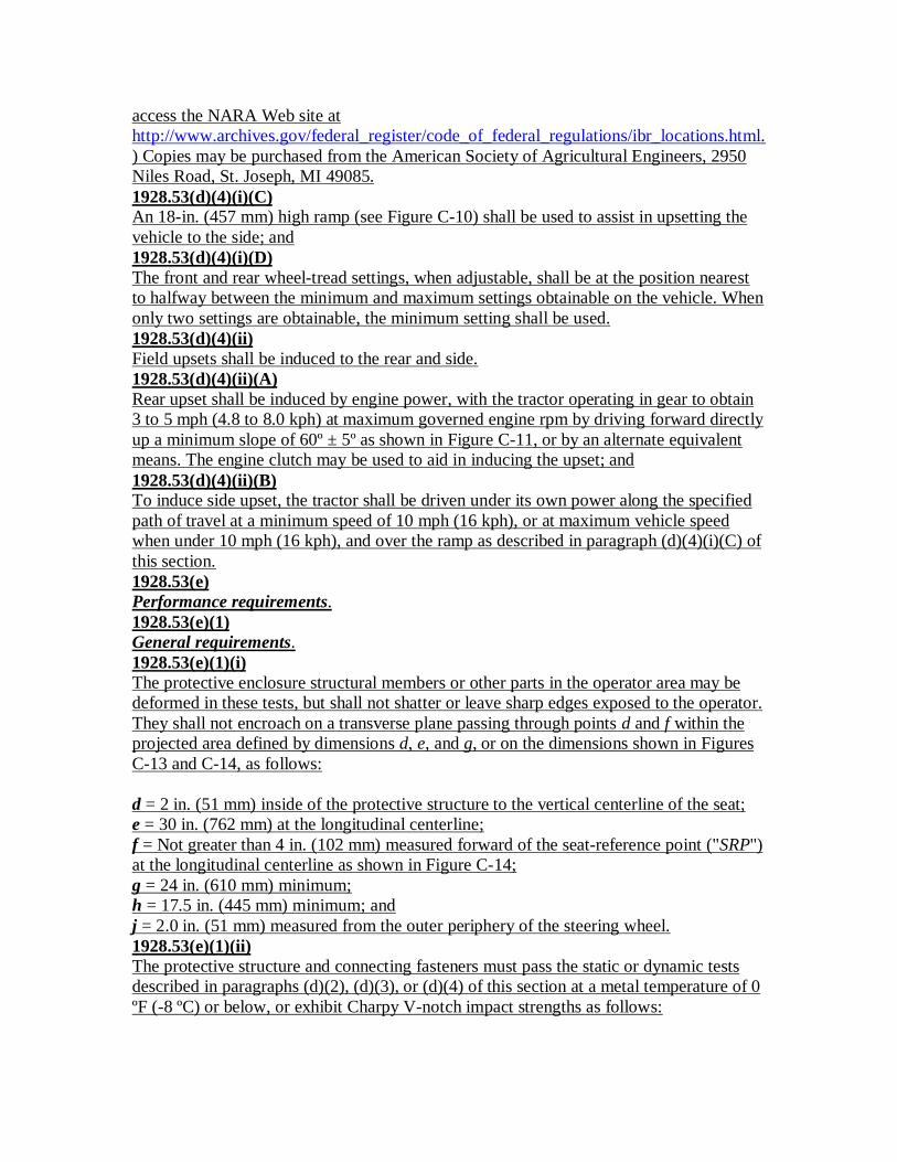
access the NARA Web site athttp://www.archives.gov/federal_register/code_of_federal_regulations/ibr_locations.html.) Copies may be purchased from the American Society of Agricultural Engineers, 2950Niles Road, St. Joseph, MI 49085.1928.53(d)(4)(i)(C)An 18-in. (457 mm) high ramp (see Figure C-10) shall be used to assist in upsetting thevehicle to the side; and1928.53(d)(4)(i)(D)The front and rear wheel-tread settings, when adjustable, shall be at the position nearestto halfway between the minimum and maximum settings obtainable on the vehicle. Whenonly two settings are obtainable, the minimum setting shall be used.1928.53(d)(4)(ii)Field upsets shall be induced to the rear and side.1928.53(d)(4)(ii)(A)Rear upset shall be induced by engine power, with the tractor operating in gear to obtain3 to 5 mph (4.8 to 8.0 kph) at maximum governed engine rpm by driving forward directlyup a minimum slope of 60º ± 5º as shown in Figure C-11, or by an alternate equivalentmeans. The engine clutch may be used to aid in inducing the upset; and1928.53(d)(4)(ii)(B)To induce side upset, the tractor shall be driven under its own power along the specifiedpath of travel at a minimum speed of 10 mph (16 kph), or at maximum vehicle speedwhen under 10 mph (16 kph), and over the ramp as described in paragraph (d)(4)(i)(C) ofthis section.1928.53(e)Performance requirements.1928.53(e)(1)General requirements.1928.53(e)(1)(i)The protective enclosure structural members or other parts in the operator area may bedeformed in these tests, but shall not shatter or leave sharp edges exposed to the operator.They shall not encroach on a transverse plane passing through points d and f within theprojected area defined by dimensions d, e, and g, or on the dimensions shown in FiguresC-13 and C-14, as follows:
d = 2 in. (51 mm) inside of the protective structure to the vertical centerline of the seat;e = 30 in. (762 mm) at the longitudinal centerline;f = Not greater than 4 in. (102 mm) measured forward of the seat-reference point ("SRP")at the longitudinal centerline as shown in Figure C-14;g = 24 in. (610 mm) minimum;h = 17.5 in. (445 mm) minimum; andj = 2.0 in. (51 mm) measured from the outer periphery of the steering wheel.1928.53(e)(1)(ii)The protective structure and connecting fasteners must pass the static or dynamic testsdescribed in paragraphs (d)(2), (d)(3), or (d)(4) of this section at a metal temperature of 0ºF (-8 ºC) or below, or exhibit Charpy V-notch impact strengths as follows:

10-mm x 10-mm (0.394-in. x 0.394-in.) specimen: 8.0 ft-lb (10.8 J) at -20 ºF (-30 ºC);10-mm x 7.5-mm (0.394-in. x 0.296-in.) specimen: 7.0 ft-lb (9.5 J) at -20 ºF (-30 ºC);10-mm x 5-mm (0.394-in. x 0.197-in.) specimen: 5.5 ft-lb (7.5 J) at -20 ºF (-30 ºC); or10-mm x 2.5-mm (0.394-in. x 0.098-in.) specimen: 4.0 ft-lb (5.5 J) at -20 ºF (-30 ºC).
Specimens shall be longitudinal and taken from flat stock, tubular, or structural sectionsbefore forming or welding for use in the protective enclosure. Specimens from tubular orstructural sections shall be taken from the middle of the side of greatest dimension, not toinclude welds.1928.53(e)(1)(iii)The following provisions address glazing requirements.1928.53(e)(1)(iii)(A)Glazing shall conform to the requirements contained in Society of Automotive Engineers("SAE") standard J674-1963 ("Safety glazing materials"), which is incorporated byreference. The incorporation by reference was approved by the Director of the FederalRegister in accordance with 5 U.S.C. 552(a) and 1 CFR part 51.1928.53(e)(1)(iii)(B)SAE standard J674-1963 appears in the 1965 SAE Handbook, or it may be examined at:any OSHA Regional Office; the OSHA Docket Office, U.S. Department of Labor, 200Constitution Avenue, NW., Room N-2625, Washington, DC 20210 (telephone: (202)693-2350 (TTY number: (877) 889-5627)); or the National Archives and RecordsAdministration ("NARA"). (For information on the availability of this material at NARA,telephone (202) 741-6030 or access the NARA Web site athttp://www.archives.gov/federal_register/code_of_federal_regulations/ibr_locations.html.) Copies may be purchased from the Society of Automotive Engineers, 400Commonwealth Drive, Warrendale, Pennsylvania 15096-0001.1928.53(e)(1)(iv)Two or more operator exits shall be provided and positioned to avoid the possibility ofboth being blocked by the same accident.1928.53(e)(2)Static test-performance requirements. In addition to meeting the requirements ofparagraph (e)(1) of this section for both side and rear loads, FERis and FERir shall begreater than 1.0.1928.53(e)(3)Dynamic test-performance requirements. The structural requirements shall be met whenthe dimensions in paragraph (e)(1) of this section are used in both side and rear loads.1928.53(e)(4)Field-upset test performance requirements. The requirements of paragraph (e)(1) of thissection shall be met for both side and rear upsets.
[61 FR 9227, March 7, 1996; 70 FR 77006, Dec. 29, 2005; 71 FR 41146, July 20, 2006]
Part Number: 1928• Part Title: Occup. Safety and Health Standards for Agriculture• Subpart: C• Subpart Title: Employee operating instruction

• StandardNumber: 1928 Subpart C Appendix A
• Title: Employee operating instruction
1. Securely fasten your seat belt if the tractor has a ROPS.2. Where possible, avoid operating the tractor near ditches, embankments, and holes.3. Reduce speed when turning, crossing slopes, and on rough, slick, or muddy surfaces.4. Stay off slopes too steep for safe operation.5. Watch where you are going, especially at row ends, on roads, and around trees.6. Do not permit others to ride.7. Operate the tractor smoothly - no jerky turns, starts, or stops.8. Hitch only to the drawbar and hitch points recommended by tractor manufacturers.9. When tractor is stopped, set brakes securely and use park lock if available.
Part Number: 1928• Part Title: Occup. Safety and Health Standards for Agriculture• Subpart: C• Subpart Title: Employee operating instruction• StandardNumber: 1928 Subpart C App B
• Title: Appendix B to Subpart C -- Figures C-1 through C-16
Subpart C Appendix B -- Figures C-1 through C-16


[70 FR 77009, Dec. 29, 2005; 71 FR 41146, July 20, 2006]
Part Number: 1928• Part Title: Occup. Safety and Health Standards for Agriculture• Subpart: D• Subpart Title: Safety for Agricultural Equipment• StandardNumber: 1928 Subpart D
• Title: Safety for Agricultural Equipment
1928.57(a)General -1928.57(a)(1)Purpose. The purpose of this section is to provide for the protection of employees fromthe hazards associated with moving machinery parts of farm field equipment, farmsteadequipment, and cotton gins used in any agricultural operation.1928.57(a)(2)Scope. Paragraph (a) of this section contains general requirements which apply to allcovered equipment. In addition, paragraph (b) of this section applies to farm fieldequipment, paragraph (c) of this section applies to farmstead equipment, and paragraph(d) of this section applies to cotton gins.1928.57(a)(3)

Application. This section applies to all farm field equipment, farmstead equipment, andcotton gins, except that paragraphs (b)(2), (b)(3), and (b)(4) (ii)(A), and (c)(2), (c)(3), and(c)(4) (ii)(A) do not apply to equipment manufactured before October 25, 1976.1928.57(a)(4)Effective date. This section takes effect on October 25, 1976, except that paragraph (d) ofthis section is effective on June 30, 1977.1928.57(a)(5)Definitions -"Cotton gins" are systems of machines which condition seed cotton, separate lint fromseed, convey materials, and package lint cotton."Farm field equipment" means tractors or implements, including self-propelledimplements, or any combination thereof used in agricultural operations."Farmstead equipment" means agricultural equipment normally used in a stationarymanner. This includes, but is not limited to, materials handling equipment andaccessories for such equipment whether or not the equipment is an integral part of abuilding."Ground driven components" are components which are powered by the turning motionof a wheel as the equipment travels over the ground.A "guard" or "shield" is a barrier designed to protect against employee contact with aheard created by a moving machinery part."Power take-off shafts" are the shafts and knuckles between the tractor, or other powersource, and the first gear set, pulley, sprocket, or other components on power take-offshaft driven equipment...1928.57(a)(6)1928.57(a)(6)Operating instructions. At the time of initial assignment and at least annually thereafter,the employer shall instruct every employee in the safe operation and servicing of allcovered equipment with which he is or will be involved, including at least the followingsafe operating practices:1928.57(a)(6)(i)Keep all guards in place when the machine is in operation;1928.57(a)(6)(ii)Permit no riders on farm field equipment other than persons required for instruction orassistance in machine operation;1928.57(a)(6)(iii)Stop engine, disconnect the power source, and wait for all machine movement to stopbefore servicing, adjusting, cleaning, or unclogging the equipment, except where themachine must be running to be properly serviced or maintained, in which case theemployer shall instruct employees as to all steps and procedures which are necessary tosafely service or maintain the equipment;1928.57(a)(6)(iv)Make sure everyone is clear of machinery before starting the engine, engaging power, oroperating the machine;1928.57(a)(6)(v)Lock out electrical power before performing maintenance or service on farmsteadequipment.

1928.57(a)(7)Methods of guarding. Except as otherwise provided in this subpart, each employer shallprotect employees from coming into contact with hazards created by moving machineryparts as follows:..1928.57(a)(7)(i)1928.57(a)(7)(i)Through the installation and use of a guard or shield or guarding by location;1928.57(a)(7)(ii)Whenever a guard or shield or guarding by location is infeasible, by using a guardrail orfence.1928.57(a)(8)Strength and design of guards.1928.57(a)(8)(i)Where guards are used to provide the protection required by this section, they shall bedesigned and located to protect against inadvertent contact with the hazard beingguarded.1928.57(a)(8)(ii)Unless otherwise specified, each guard and its supports shall be capable of withstandingthe force that a 250 pound individual, leaning on or falling against the guard, would exertupon that guard.1928.57(a)(8)(iii)Guards shall be free from burrs, sharp edges, and sharp corners, and shall be securelyfastened to the equipment or building.1928.57(a)(9)Guarding by location. A component is guarded by location during operation,maintenance, or servicing when, because of its location, no employee can inadvertentlycome in contact with the hazard during such operation, maintenance, or servicing. Wherethe employer can show that any exposure to hazards results from employee conductwhich constitutes an isolated and unforeseeable event, the component shall also beconsidered guarded by location...1928.57(a)(10)1928.57(a)(10)Guarding by railings. Guardrails or fences shall be capable of protecting againstemployees inadvertently entering the hazardous area.1928.57(a)(11)Servicing and maintenance. Whenever a moving machinery part presents a hazard duringservicing or maintenance, the engine shall be stopped, the power source disconnected,and all machine movement stopped before servicing or maintenance is performed, exceptwhere the employer can establish that:1928.57(a)(11)(i)The equipment must be running to be properly serviced or maintained;1928.57(a)(11)(ii)The equipment cannot be serviced or maintained while a guard or guards otherwiserequired by this standard are in place; and1928.57(a)(11)(iii)The servicing or maintenance can be safely performed.

1928.57(b)Farm field equipment -1928.57(b)(1)Power take-off guarding.1928.57(b)(1)(i)All power take-off shafts, including rear, mid- or side-mounted shafts, shall be guardedeither by a master shield, as provided in paragraph (b)(1)(ii) of this section, or by otherprotective guarding...1928.57(b)(1)(ii)1928.57(b)(1)(ii)All tractors shall be equipped with an agricultural tractor master shield on the rear powertake-off except where removal of the tractor master shield is permitted by paragraph(b)(1)(iii) of this section. The master shield shall have sufficient strength to preventpermanent deformation of the shield when a 250 pound operator mounts or dismounts thetractor using the shield as a step.1928.57(b)(1)(iii)Power take-off driven equipment shall be guarded to protect against employee contactwith positively driven rotating members of the power drive system. Where power take-off driven equipment is of a design requiring removal of the tractor master shield, theequipment shall also include protection from that portion of the tractor power take-offshaft which protrudes from the tractor.1928.57(b)(1)(iv)Signs shall be placed at prominent locations on tractors and power take-off drivenequipment specifying that power drive system safety shields must be kept in place.1928.57(b)(2)Other power transmission components.1928.57(b)(2)(i)The mesh or nip-points of all power driven gears, belts, chains, sheaves, pulleys,sprockets, and idlers shall be guarded.1928.57(b)(2)(ii)All revolving shafts, including projections such as bolts, keys, or set screws, shall beguarded, except smooth shaft ends protruding less than one-half the outside diameter ofthe shaft and its locking means.1928.57(b)(2)(iii)Ground driven components shall be guarded in accordance with paragraphs (b)(2)(i) and(b)(2)(ii) of this section if any employee may be exposed to them while the drives are inmotion...1928.57(b)(3)1928.57(b)(3)Functional components. Functional components, such as snapping or husking rolls, strawspreaders and choppers, cutterbars, flail rotors, rotary beaters, mixing augers, feed rolls,conveying augers, rotary tillers, and similar units, which must be exposed for properfunction, shall be guarded to the fullest extent which will not substantially interfere withnormal functioning of the component.1928.57(b)(4)Access to moving parts.

1928.57(b)(4)(i)Guards, shields, and access doors shall be in place when the equipment is in operation.1928.57(b)(4)(ii)Where removal of a guard or access door will expose an employee to any componentwhich continues to rotate after the power is disengaged, the employer shall provide, in theimmediate area, the following:1928.57(b)(4)(ii)(A)A readily visible or audible warning of rotation; and1928.57(b)(4)(ii)(B)A safety sign warning the employee to:1928.57(b)(4)(ii)(B)(1)Look and listen for evidence of rotation; and1928.57(b)(4)(ii)(B)(2)Not remove the guard or access door until all components have stopped.1928.57(c)Farmstead equipment -1928.57(c)(1)Power take-off guarding.1928.57(c)(1)(i)All power take-off shafts, including rear, mid-, or side-mounted shafts, shall be guardedeither by a master shield as provided in paragraph (b)(l)(ii) of this section or otherprotective guarding...1928.57(c)(1)(ii)1928.57(c)(1)(ii)Power take-off driven equipment shall be guarded to protect against employee contactwith positively driven rotating members of the power drive system. Where power take-off driven equipment is of a design requiring removal of the tractor master shield, theequipment shall also include protection from that portion of the tractor power take-offshaft which protrudes from the tractor.1928.57(c)(1)(iii)Signs shall be placed at prominent locations on power take-off driven equipmentspecifying that power drive system safety shields must be kept in place.1928.57(c)(2)Other power transmission components.1928.57(c)(2)(i)The mesh or nip-points of all power driven gears, belts, chains, sheaves, pulleys,sprockets, and idlers shall be guarded.1928.57(c)(2)(ii)All revolving shafts, including projections such as bolts, keys, or set screws, shall beguarded, with the exception of:1928.57(c)(2)(ii)(A)Smooth shafts and shaft ends (without any projecting bolts, keys or set screws), revolvingat less than 10 rpm, on feed handling equipment used on the top surface of materials inbulk storage facilities; and1928.57(c)(2)(ii)(B)

Smooth shaft ends protruding less than one-half the outside diameter of the shaft and itslocking means...1928.57(c)(3)1928.57(c)(3)Functional components.1928.57(c)(3)(i)Functional components, such as choppers, rotary beaters, mixing augers, feed rolls,conveying augers, grain spreaders, stirring augers, sweep augers, and feed augers, whichmust be exposed for proper function, shall be guarded to the fullest extent which will notsubstantially interfere with the normal functioning of the component.1928.57(c)(3)(ii)Sweep arm material gathering mechanisms used on the top surface of materials withinsilo structures shall be guarded. The lower or leading edge of the guard shall be locatedno more than 12 inches above the material surface and no less than 6 inches in front ofthe leading edge of the rotating member of the gathering mechanism. The guard shall beparallel to, and extend the fullest practical length of, the material gathering mechanism.1928.57(c)(3)(iii)Exposed auger flighting on portable grain augers shall be guarded with either grating typeguards or solid baffle style covers as follows:1928.57(c)(3)(iii)(A)The largest dimensions or openings in grating type guards through which materials arerequired to flow shall be 4 3/4 inches. The area of each opening shall be no larger than 10square inches. The opening shall be located no closer to the rotating flighting than 2 1/2inches.1928.57(c)(3)(iii)(B)Slotted openings in solid baffle style covers shall be no wider than 1 1/2 inches, or closerthan 3 1/2 inches to the exposed flighting.1928.57(c)(4)Access to moving parts.1928.57(c)(4)(i)Guards, shields, and access doors shall be in place when the equipment is in operation...1928.57(c)(4)(ii)1928.57(c)(4)(ii)Where removal of a guard or access door will expose an employee to any componentwhich continues to rotate after the power is disengaged, the employer shall provide, in theimmediate area, the following:1928.57(c)(4)(ii)(A)A readily visible or audible warning of rotation; and1928.57(c)(4)(ii)(B)A safety sign warning the employee to:1928.57(c)(4)(ii)(B)(1)Look and listen for evidence of rotation; and1928.57(c)(4)(ii)(B)(2)Not remove the guard or access door until all components have stopped.1928.57(c)(5)Electrical disconnect means.

1928.57(c)(5)(i)Application of electrical power from a location not under the immediate and exclusivecontrol of the employee or employees maintaining or servicing equipment shall beprevented by:1928.57(c)(5)(i)(A)Providing an exclusive, positive locking means on the main switch which can be operatedonly by the employee or employees performing the maintenance or servicing; or1928.57(c)(5)(i)(B)In the case of material handling equipment located in a bulk storage structure, byphysically locating on the equipment an electrical or mechanical means to disconnect thepower...1928.57(c)(5)(ii)1928.57(c)(5)(ii)All circuit protection devices, including those which are an integral part of a motor, shallbe of the manual reset type, except where:1928.57(c)(5)(ii)(A)The employer can establish that because of the nature of the operation, distancesinvolved, and the count of time normally spent by employees in the area of the affectedequipment, use of the manual reset device would be infeasible;1928.57(c)(5)(ii)(B)There is an electrical disconnect switch available to the employee within 15 feet of theequipment upon which maintenance or service is being performed; and1928.57(c)(5)(ii)(C)A sign is prominently posted near each hazardous component which warns the employeethat, unless the electrical disconnect switch is utilized, the motor could automaticallyreset while the employee is working on the hazardous component.1928.57(d)Cotton ginning equipment -1928.57(d)(1)Power transmission components.1928.57(d)(1)(i)The main drive and miscellaneous drives of gin stands shall be completely enclosed,guarded by location, or guarded by railings (consistent with the requirements ofparagraph (a)(7) of this section). Drives between gin stands shall be guarded so as toprevent access to the area between machines...1928.57(d)(1)(ii)1928.57(d)(1)(ii)When guarded by railings, any hazardous component within 15 horizontal inches of therail shall be completely enclosed. Railing height shall be approximately 42 inches off thefloor, platform, or other working surface, with a midrail between the top-rail and theworking surface. Panels made of materials conforming to the requirements in Table D-1,or equivalent, may be substituted for midrails. Guardrails shall be strong enough towithstand at least 200 pounds force on the toprail.1928.57(d)(1)(iii)Belts guarded by railings shall be inspected for defects at least daily. The machinery shallnot be operated until all defective belts are replaced.
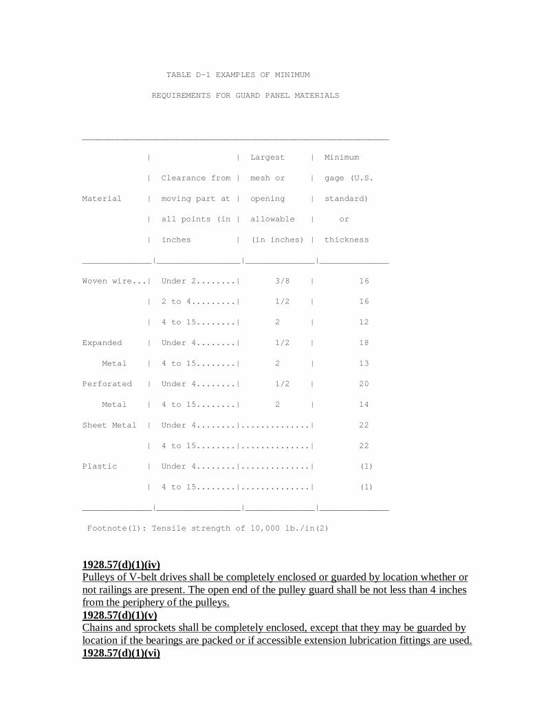
TABLE D-1 EXAMPLES OF MINIMUM
REQUIREMENTS FOR GUARD PANEL MATERIALS
______________________________________________________________
| | Largest | Minimum
| Clearance from | mesh or | gage (U.S.
Material | moving part at | opening | standard)
| all points (in | allowable | or
| inches | (in inches) | thickness
______________|_________________|______________|______________
Woven wire...| Under 2........| 3/8 | 16
| 2 to 4.........| 1/2 | 16
| 4 to 15........| 2 | 12
Expanded | Under 4........| 1/2 | 18
Metal | 4 to 15........| 2 | 13
Perforated | Under 4........| 1/2 | 20
Metal | 4 to 15........| 2 | 14
Sheet Metal | Under 4........|..............| 22
| 4 to 15........|..............| 22
Plastic | Under 4........|..............| (1)
| 4 to 15........|..............| (1)
______________|_________________|______________|______________
Footnote(1): Tensile strength of 10,000 lb./in(2)
1928.57(d)(1)(iv)Pulleys of V-belt drives shall be completely enclosed or guarded by location whether ornot railings are present. The open end of the pulley guard shall be not less than 4 inchesfrom the periphery of the pulleys.1928.57(d)(1)(v)Chains and sprockets shall be completely enclosed, except that they may be guarded bylocation if the bearings are packed or if accessible extension lubrication fittings are used.1928.57(d)(1)(vi)

Where complete enclosure of a component is likely to cause a fire hazard due toexcessive deposits of lint, only the face section of nip-point and pulley guards is required.The guard shall extend at least 6 inches beyond the rim of the pulley on the in-runningand off-running sides of the belt, and at least 2 inches from the rim and face of the pulleyin all other directions...1928.57(d)(1)(vii)1928.57(d)(1)(vii)Projecting shaft ends not guarded by location shall present a smooth edge and end, shallbe guarded by non-rotating caps or safety sleeves, and may not protrude more than one-half the outside diameter of the shaft.1928.57(d)(1)(viii)In power plants and power development rooms where access is limited to authorizedpersonnel, guard railings may be used in place of guards or guarding by location.Authorized employees having access to power plants and power development rooms shallbe instructed in the safe operation and maintenance of the equipment in accordance withparagraph (a)(6) of this section.1928.57(d)(2)Functional components.1928.57(d)(2)(i)Gin stands shall be provided with a permanently installed guard designed to precludecontact with the gin saws while In motion. The saw blades in the roll box shall beconsidered guarded by location if they do not extend through the ginning ribs into the rollbox when the breast is in the out position.1928.57(d)(2)(ii)Moving saws on lint cleaners which have doors giving access to the saws shall beguarded by fixed barrier guards or their equivalent which prevent direct finger or handcontact with the saws while the saws are in motion.1928.57(d)(2)(iii)An interlock shall be installed on all balers so that the upper gates cannot be openedwhile the tramper is operating...1928.57(d)(2)(iv)1928.57(d)(2)(iv)Top panels of burr extractors shall be hinged and equipped with a sturdy positive latch.1928.57(d)(2)(v)All accessible screw conveyors shall be guarded by substantial covers or gratings, or withan inverted horizontally slotted guard of the trough type, which will prevent employeesfrom coming into contact with the screw conveyor. Such guards may consist of horizontalbars spaced so as to allow material to be fed into the conveyor, and supported by archeswhich are not more than 8 feet apart. Screw conveyors under gin stands shall beconsidered guarded by location.1928.57(d)(3)Warning device. A warning device shall be installed in all gins to provide an audiblesignal which will indicate to employees that any or all of the machines comprising the ginare about to be started. The signal shall be of sufficient volume to be heard by employees,and shall be sounded each time before starting the gin.
[41 FR 10195, Mar. 9, 1976; 41 FR 11022, Mar. 16, 1976; 41 FR 22268, June 2, 1976, asamended at 41 FR 46598, Oct. 22, 1976]
Part Number: 1928• Part Title: Occup. Safety and Health Standards for Agriculture• Subpart: E• Subpart Title: [Reserved]• StandardNumber: 1928 Subpart E
• Title: [Reserved]
[Reserved]
Part Number: 1928• Part Title: Occup. Safety and Health Standards for Agriculture• Subpart: F• Subpart Title: [Reserved]• StandardNumber: 1928 Subpart F
• Title: [Reserved]
[Reserved]
Part Number: 1928• Part Title: Occup. Safety and Health Standards for Agriculture• Subpart: G• Subpart Title: [Reserved]• StandardNumber: 1928 Subpart G
• Title: [Reserved]
[Reserved]

Part Number: 1928• Part Title: Occup. Safety and Health Standards for Agriculture• Subpart: H• Subpart Title: [Reserved]• StandardNumber: 1928 Subpart H
• Title: [Reserved]
[Reserved]
Part Number: 1928• Part Title: Occup. Safety and Health Standards for Agriculture• Subpart: I• Subpart Title: General Environmental Controls• StandardNumber: 1928 Subpart I
• Title: General Environmental Controls
1928.110(a)Scope. This section shall apply to any agricultural establishment where eleven (11) ormore employees are engaged on any given day in hand-labor operations in the field.1928.110(b)Definitions.
Agricultural employer means any person, corporation, association, or other legal entitythat:
[i] Owns or operates an agricultural establishment;
[ii] Contracts with the owner or operator of an agricultural establishment in advance ofproduction for the purchase of a crop and exercises substantial control over production;or
[iii] Recruits and supervises employees or is responsible for the management an conditionof an agricultural establishment.
Agricultural establishment is a business operation that uses paid employees in the
production of food, fiber, or other materials such as seed, seedlings, plants, or parts ofplants.
Hand-labor operations means agricultural activities or agricultural operations performedby hand or with hand tools. Except for purposes of paragraph (c)(2)(iii) of this section,"hand labor operations" also include other activities or operations performed inconjunction with hand labor in the field. Some examples of "hand labor operations" arethe hand-cultivation, hand-weeding, hand-planting and hand-harvesting of vegetables,nuts, fruits, seedlings or other crops, including mushrooms, and the hand packing ofproduce into containers, whether done on the ground, on a moving machine or in atemporary packing shed located in the field. "Hand-labor" does not include such activitiesas logging operations, the care or feeding of livestock, or hand-labor operations inpermanent structures (e.g., canning facilities or packing houses).
Handwashing facility means a facility providing either a basin, container, or outlet withan adequate supply of potable water, soap and single-use towels.
Potable water means water that meets the standards for drinking purposes of the State orlocal authority having jurisdiction, or water that meets the quality standards prescribed bythe U.S. Environmental Protection Agency's National Primary Drinking WaterRegulations (40 CFR part 141).
Toilet facility means a fixed or portable facility designed for the purpose of adequatecollection and containment of the products of both defecation and urination which isapplied with toilet paper adequate to employee needs. Toilet facility includes biological,chemical, flush and combustion toilets and sanitary privies.1928.110(c)Requirements. Agricultural employers shall provide the following for employees engagedin hand-labor operations in the field, without cost to the employee:1928.110(c)(1)Potable drinking water.1928.110(c)(1)(i)Potable water shall be provided and placed in locations readily accessible to allemployees.1928.110(c)(1)(ii)The water shall be suitably cool and in sufficient amounts, taking into account the airtemperature, humidity and the nature of the work performed, to meet the needs of allemployees.1928.110(c)(1)(iii)The water shall be dispensed in single-use drinking cups or by fountains. The use ofcommon drinking cups or dippers is prohibited.1928.110(c)(2)Toilet and handwashing facilities.1928.110(c)(2)(i)One toilet facility and one handwashing facility shall be provided for each (20)employees or fraction thereof, except as stated in paragraph (c)(2)(v) of this section.

1928.110(c)(2)(ii)Toilet facilities shall be adequately ventilated, appropriately screened, have self-closingdoors that can be closed and latched from the inside and shall be constructed to insureprivacy.1928.110(c)(2)(iii)Toilet and handwashing facilities shall be accessibly located an in close proximity to eachother. The facilities shall be located within a one-quarter-mile walk of each hand laborer'splace of work in the field.1928.110(c)(2)(iv)Where due to terrain it is not feasible to locate facilities as required above, the facilitiesshall be located at the point closest vehicular access.1928.110(c)(2)(v)Toilet and handwashing facilities are not required for employees who perform field workfor a period of three (3) hours or less (including transportation time to and from the field)during the day.1928.110(c)(3)Maintenance. Potable drinking water and toilet and handwashing facilities shall bemaintained in accordance with appropriate public health sanitation practices, includingthe following:1928.110(c)(3)(i)Drinking water containers shall be constructed of materials that maintain water quality,shall be refilled daily or more often as necessary, shall be kept covered and shall beregularly cleaned.1928.110(c)(3)(ii)Toilet facilities shall be operational and maintained in clean and sanitary condition.1928.110(c)(3)(iii)Handwashing facilities shall be refilled with potable water as necessary to ensure anadequate supply and shall be maintained in a clean and sanitary condition; and1928.110(c)(3)(iv)Disposal of wastes from facilities shall not cause unsanitary conditions.1928.110(c)(4)Reasonable use. The employer shall notify each employee of the location of the sanitationfacilities and water and shall allow each employee reasonable opportunities during theworkday to use them. The employer also shall inform each employee of the importanceof each of the following good hygiene practices to minimize exposure to the hazards inthe field of heat, communicable diseases, retention of urine and agrichemical residues.1928.110(c)(4)(i)Use the water and facilities provided for drinking, handwashing and elimination.1928.110(c)(4)(ii)Drink water frequently and especially on hot days;1928.110(c)(4)(iii)Urinate as frequently as necessary;1928.110(c)(4)(iv)Wash hands both before and after using the toilet; and1928.110(c)(4)(v)Wash hands before eating and smoking.
1928.110(d)Dates -1928.110(d)(1)Effective Date. This standard shall take effect on May 30, 1987.1928.110(d)(2)Startup Dates. Employers must comply with the requirements of paragraphs:1928.110(d)(2)(i)Paragraph (c)(1), to provide potable drinking water, by May 30, 1987;1928.110(d)(2)(ii)Paragraph (c)(2), to provide handwashing and toilet facilities, by July 30, 1987;1928.110(d)(2)(iii)Paragraph (c)(3), to provide maintenance for toilet and handwashing facilities, by July30, 1987; and1928.110(d)(2)(iv)Paragraph (c)(4), to assure reasonable use, by July 30, 1987.
[52 FR 16095, May 1, 1987; 76 FR 33612, June 8, 2011]
Part Number: 1928• Part Title: Occup. Safety and Health Standards for Agriculture• Subpart: J• Subpart Title: [Reserved]• StandardNumber: 1928 Subpart J
• Title: [Reserved]
[Reserved]
Part Number: 1928• Part Title: Occup. Safety and Health Standards for Agriculture• Subpart: K• Subpart Title: [Reserved]• StandardNumber: 1928 Subpart K
• Title: [Reserved]
[Reserved]
Part Number: 1928• Part Title: Occup. Safety and Health Standards for Agriculture• Subpart: L• Subpart Title: [Reserved]• StandardNumber: 1928 Subpart L
• Title: [Reserved]
[Reserved]
Part Number: 1928• Part Title: Occup. Safety and Health Standards for Agriculture• Subpart: M• Subpart Title: Occupational Health• StandardNumber: 1928 Subpart M
• Title: Occupational Health
1928.1027See 1910.1027, Cadmium.
[57 FR 42389, Sept. 14, 1992; 57 FR 49272, Oct. 30, 1992; 58 FR 21782, April 23, 1993;61 FR 9227, March 7, 1996]