Embed Size (px)
Citation preview

Westinghouse Technology Manual Course Administration
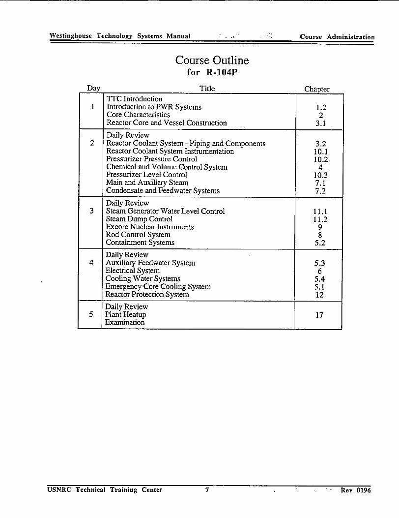
Course Outline for R-104P
Day Title Chapter
TTC Introduction Introduction to PWR Systems 1.2 Core Characteristics 2 Reactor Core and Vessel Construction 3.1
Daily Review 2 Reactor Coolant System - Piping and Components 3.2
Reactor Coolant System Instrumentation 10.1 Pressurizer Pressure Control 10.2 Chemical and Volume Control System 4 Pressurizer Level Control 10.3 Main and Auxiliary Steam 7.1 Condensate and Feedwater Systems 7.2
Daily Review 3 Steam Generator Water Level Control 11.1
Steam Dump Control 11.2 Excore Nuclear Instruments 9 Rod Control System 8 Containment Systems 5.2
Daily Review 4 Auxiliary Feedwater System 5.3
Electrical System 6 Cooling Water Systems 5.4 Emergency Core Cooling System 5.1 Reactor Protection System 12
Daily Review 5 Plant Heatup 17
Examination
USNRCTechicalTraiing Cnter1 Rel099
Westinghouse Technology Manual Course Administration
Rev 0998USNRC Technical Training Center 1
Westinghouse Technology Manual Preface
UNITED STATES NUCLEAR REGULATORY COMMISSION
TECHNICAL TRAINING CENTER
WESTINGHOUSE TECHNOLOGY
MANUAL
This manual is a text and reference document for the Westinghouse Technology Course. It should be used by students as a study guide during attendence at this course. This manual was compiled by staff members of the Technical Training Division in the Office for Analysis and Evaluation of Operational Data.
The information in this manual was developed or compiled for NRC personnel in support of internal training and qualification programs. No assumptions should be made as to its applicability for any other purpose. Information or statements contained in this manual should not be interpreted as setting official NRC policy. The data provided are not necessarily specific to any particular nuclear power plant, but can be considered to be representative of the vendor design.
USNRC Technical Training Center Rev 0195
Westinghouse Technology Manual Preface
Rev 0195USNRC Technical Training Center i

Westinghouse Technology Manual Introduction
INTRODUCTION TO THE PRESSURIZED WATER REACTOR (PWR) TECHNOLOGY MANUAL
The PWR Technology manual is provided as a reference document to supplement the materials presented in the PWR 100 Level and 200 Level Technology Courses. The material in the manual will provide the major source of information during the presentation of these courses.
The PWR Technology manual discusses the Westinghouse Pressurized Water Reactor Technology in general, and uses the Westinghouse four loop design as the specific example of this technology.
The materials presented in the manual are provided in sufficient detail that, when combined with the corresponding classroom presentations, the student should obtain a level of understanding of the materials presented to knowledgeably discuss a Westinghouse PWR. Setpoints, where given, are typical values provided to enhance the understanding of system design and operations.
This manual contains detailed design and operational information possibly considered "Proprietary" by certain companies that design and supply the components and systems for nuclear facilities. This manual was developed strictly for the use of NRC personnel during training and for subsequent reference purposes and should not be distributed outside of the NRC.
USNRC Technical Training Center Rev 0495
Westinghouse Technology Manual Introduction
USNRC Technical Training Center Rev 0495
Course Information
TTC PHONE SYSTEM
1. Commercial: 423/855-6500 2 Incoming calls for students - see paragraph on STUDENT MESSAGES 3. Classroom phones are a common internal line and can only be used to call other areas inside the
Training Center.,, -4., Wall phones in the 1st, 2nd, 3rd, and 4th' floor studefit lounge areas can be used for students,
"ifmakingoutside calls.",. 5. To make local calls: dial 9 -- local number . 6. :To make long distance calls: -dial 8 -*Area Code - Number
Note: TIC is now on detailed billing for actual telephone usage and all calls are listed on a computer printout. Please limit calls home to no more 'than 5 hminutes,- per NRC Mahual Chapter Appendix 1501, Part IV.D.5.
AREA INFORMATION
1. Restaurants - Eastgate Mall, Brainerd Road area 2. Hospital - Humana in East Ridge - Phone: 894-7870 3. Emergency Phone Number - 911 ' - -
COURSE RELATED ITEMS
1. Working hours are from 7:30 a.m. to 4:15 p.m. Classroom presentations are from 8:00 a.m. to 4:00 p.m. Lunch break will begin between 11:30 a.m. - 12:00 p.m. at the discretion of the instructor. If a swing shift simulator is required for the R-200P course, the official working hours are 3:15 to 12:00 midnight. Presentations on the simulator will be from 4:00 to 12:00 midnight. A break for dinner will begin between 7:30 and 8:00, at the discretion of the instructor.
2. The Course Director and Course Instructor(s) are available to answer questions before and after class, during the breaks, and during lunch time with prior arrangement. Instructors not in the classroom can be reached via the inside phone. Please call ahead to ensure availability.
3. All course related materials (pencil, paper, manuals, notebooks, and markers) are provided. If there is a need for additional material or administrative service, please coordinate with the Course Instructors.
4. Shipping boxes will be provided to the students for the mailing of course materials (manuals & notebooks). Each student must write their name and address to which the box is to be mailed on a mailing label and tape it to the outside of their box. The TrC staff will affix the proper postage.
5. Student registration for all TTC courses is accomplished through Training Coordinators. The TTC
staff does not register students directly.
TTC SECURITY
NRC badges will be required to be worn while at the TTC. Please promptly notify Course Director if badge is lost or misplaced.
USNRC Technical Training Center - Key .iiY�1
,Westinghouse Technology Manual I Course Administration
-..Kev 1295" USNRC Technical Training Center
STUDENT MESSAGES
There is a printer located in the third floor lounge area. All non-emergency student messages will be sent to this printer. It is the responsibility of the students to check this printer for messages-; If there are messages on the printer students are asked to post them on the bulletin board above the printer.
FIRST AID KITS
First Aid Kits are located in the instructors desk of each simulator, in the second floor and third and fourth floor student lounges in the sink cabinets, and the sink cabinet in the staff, lounge on the second floor. In addition, each location also has a "Body Fluid Barrier Kit". These kits are to be used in the event of personnel injury involving serious bleeding. Each kit contains two complete packets each with: 1 pair of latex gloves, 1 face shield, 1 mouth-to-mouth barrier, 1 protective garment, 2 antiseptic towelettes, and 1 biohazard disposable bag.
TAX EXEMPTION CERTIFICATES
NOTE: We do not have Tax Exempt Certificates for lodging in Chattanooga, Chattanooga is not one of the localities permitted to use these certificates. For a list of locations which are allowed to use them, see the Federal Travel Directory published monthly by GSA.
Please remember that you, as students, represent the NRC and when you knowingly avoid paying Tennessee State Tax, the results can have a negative effect on the Agency.
If you are not able to obtain adequate lodging and stay within the per diem rate established by GSA, advise your Management Support or DRMA office so the proper authorities can be notified.
USNRC Technical Training Center
Westinghouse Technology Manual Course Administration
2 Rey 1295
�Westinghouse Technology Manual Course Administration
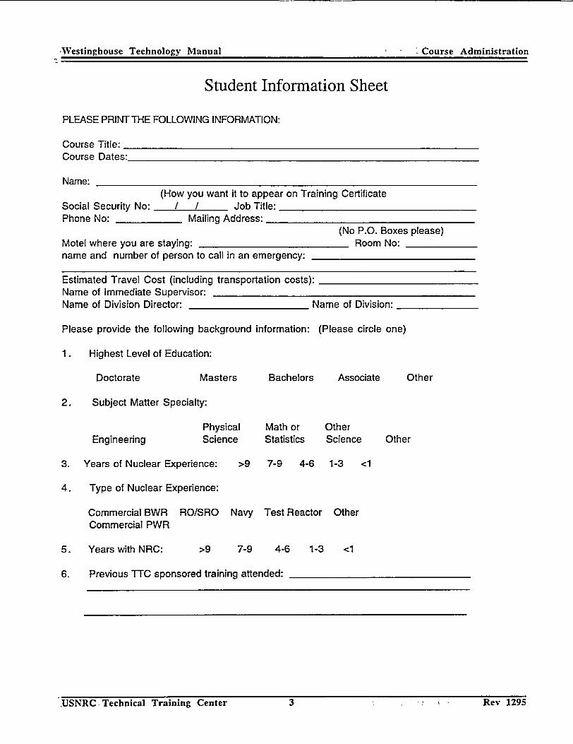
Student Information Sheet
PLEASE PRINT THE FOLLOWING INFORMATION:
Course Title: Course Dates:
Name: (How you want it to appear on Training Certificate
Social Security No: / - Job Title: Phone No: Mailing Address:
(No P.O. Boxes please) Motel where you are staying: Room No: name and number of person to call in an emergency:
Estimated Travel Cost (including transportation costs): Name of Immediate Supervisor: Name of Division Director: Name of Division:
Please provide the following background information: (Please circle one)
1. Highest Level of Education:
Doctorate Masters Bachelors Associate Other
2. Subject Matter Specialty:
3.
4.
5.
6.
Physical Math Engineering Science Statist
Years of Nuclear Experience: >9 7-9
Type of Nuclear Experience:
Commercial BWR RO/SRO Navy Test F Commercial PWR
Years with NRC: >9 7-9 4-6
Previous TTC sponsored training attended: -
or
tics
4-6
leactor
Other Science
1-3 <1
Other
Other
1-3 <1
USNRC Technical Training Center 3 Rev 1295
-Westinghouse Technology Manual S Course Administration
3 Rev 1295,USNRC- Technical Training Center
Westinghouse Technology Manual Course Administration
USNRC Technical Training Center 4 Rev 1295
Westinghouse Technology Manual Course Administration
USNRC, Technical Training Center 4 Rev 1295

COURSE OBJECTIVES S(R-104P)
The Westinghouse technology course is designed to provide the student with a general familiarity with the mechanical, instrumentation and control, and protective systems of the Westinghouse design. At the end of this course each student should have achieved a basic understanding of the following:
"* Reactivity coefficients, "* Functions and flow paths of major mechanical systems, and * Process instrumentation systems, including inputs and control and protection functions.
USNRC Technical Training Center 5
Westinghouse Technology Manual Course Administration
Rev 1295

COURSE OBJECTIVES (R-200P)
The Westinghouse technology course is designed to provide the student, with a general understanding of the Westinghouse 'design with' emphasis in system design, function, instrumentation; interlocks, and interrelationships. A full scope control room simulator will be used to reinforce the information taught in the classroom. At the end of this course each student should have achieved a basic understanding of the following:
* Nuclear theory and reactivity coefficients, * Process mechanical systems, including purposes, theory of operation, normal system
configuration, and safety related flow paths, * Plant electrical system design and distribution, * Process instrumentation systems, including purposes, input signals, selected interlocks, and
control and protection functions.
USNRC Technical Training Center Rev 1295
Westinghouse Technology Manual Course Administration
6
Westinghouse Technology Systems Manual Course Administration
Course Outline for R-104P
Day Title Chapter
USNRC Technical Training Center 7 Rev 0196
TTC Introduction I Introduction to PWR Systems 1.2
Core Characteristics 2 Reactor Core and Vessel Construction 3.1
Daily Review 2 Reactor Coolant System - Piping and Components 3.2
Reactor Coolant System Instrumentation 10.1 Pressurizer Pressure Control 10.2 Chemical and Volume Control System 4 Pressurizer Level Control 10.3 Main and Auxiliary Steam 7.1 Condensate and Feedwater Systems 7.2
Daily Review 3 Steam Generator Water Level Control 11.1
Steam Dump Control 11.2 Excore Nuclear Instruments 9 Rod Control System 8 Containment Systems 5.2
Daily Review 4 Auxiliary Feedwater System 5.3
Electrical System 6 Cooling Water Systems 5.4 Emergency Core Cooling System 5.1 Reactor Protection System 12
Daily Review 5 Plant Heatup 17
Examination
Rev 0196
Westinghouse Technology Systems Manual Course Administration
USNRC Technical Training Center 7
Westnghose Tchnoogy ystesMaual- Course Administi~ation
USNRC Technical Training Center Rev 0196
Westinghouse Technology Systems Manual
8
Westinghouse -Technology Systems Manual Course Administration
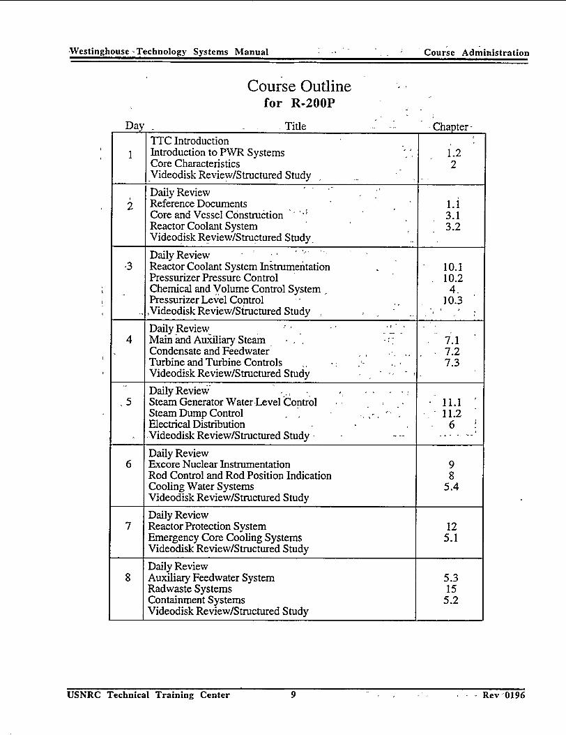
Course Outline for R-200P
Day Title Chapter-TTC Introduction Introduction to PWR Systems 1.2 Core Characteristics 2 Videodisk Review/Structured Study
Daily Review SReference Documents 1.1
Core and Vessel C6nstruction 3.1 Reactor Coolant System 3.2 Videodisk Review/Structured Study ..
Daily Review -3 Reactor Coolant System Instrumentation 10.1
Pressurizer Pressure Control 10.2 Chemical and Volume Control System 4Pressurizer Level Control - 10.3
oVideodisk Review/Siructured Study Daily Review .
4 Main and Auxiliary Steamr 7.1 Condensate and Feedwater 7.2 Turbine and Turbine Controls 7.3 Videodisk Review/Structured Study _ _ _
Daily Review .f 5 Steam Generator Water-Level Control , 11.1
Steam Dump Control 11.2 Electrical Distribution 6 -Videodisk Review/Structured Study .
Daily Review 6 Excore Nuclear Instrumentation 9
Rod Control and Rod Position Indication 8 Cooling Water Systems 5.4 Videodisk Review/Structured Study
Daily Review 7 Reactor Protection System 12
Emergency Core Cooling Systems 5.1 Videodisk Review/Structured Study
Daily Review 8 Auxiliary Feedwater System 5.3
Radwaste Systems 15 Containment Systems 5.2 Videodisk Review/Structured Study
USNRC Technical Training Center 9 - - - - - Rev 0196
,Westinghouse -Technology Systems Manual Course Administration
USNRC Technical Training Center 9 I_ - • • I - Rev -0196

Westinghouse Technology Systems Manual
USNRC Technical Training Center 10 Rev 019610 Rev 0196
Daily Review 9 Refueling Systems 14
Radiation Monitoring 16 Plant Operations 17
Comprehensive Review 10 Question and Answer
Self Study Final Exam
Simulator Panel Indoctrination 11 General Startup Procedure Simulator
Rod Control and Nuclear Instrumentation Review, Reactor Startup Demonstration Review
Condensate and Feedwater Systems Review 12 Steam Generator Level Control Operations Simulator
CVCS and Makeup System Operations Auxiliary Feedwater
Main Steam and Steam Dump Discussions/Demos 13 Turbine Generator Operations Simulator
Plant Operations - Power Changes
Residual Heat Removal Systems Discussions 14 Plant Shutdown/Cooldown Simulator
Shutdown/Cooldown from 50% Power Solid Plant Operations
Cooling Water Systems Discussions 15 Demonstrations of effects of Loss of Cooling Simulator
Electrical Distribution Discussions Abnormal and Accident Scenarios
I
USNRC Technical Training Center
W'ctmnhohusce Technolo y Svstems ManualCoreAmntain
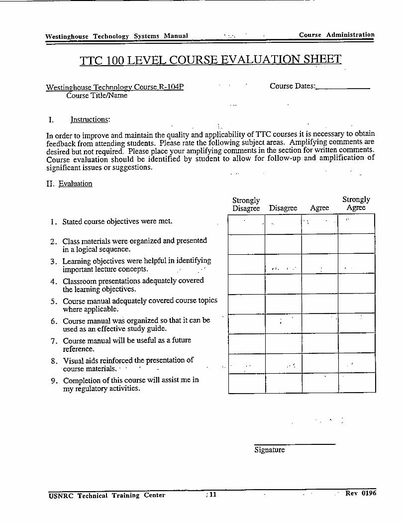
TTC 100 LEVEL COURSE EVALUATION SHEET
Westinghouse Technology Course R-104P Course Dates:_ Course Title/Name
I. Instructions:
In order to improve and maintain the quality and applicability of TTC courses it is necessary to obtain feedback from attending students. Please rate the following subject areas. Amplifying comments are desired but not required. Please place your amplifying comments in the section for written comments. Course evaluation should be identified by student to allow for follow-up and amplification of significant issues or suggestions.
II. Evaluation
Strongly Strongly Disagree Disagree Agree Agree
1. Stated course objectives were met. .
2. Class materials were organized and presented in a logical sequence.
3. Learning objectives were helpful in identifying important lecture concepts. __.... :,____
4. Classroom presentations adequately covered the learning objectives.
5. Course manual adequately covered course topics where applicable.
6. Course manual was organized so that it can be used as an effective study guide.
7. Course manual will be useful as a future reference.
8. Visual aids reinforced the presentation of -course materials. - "
9. Completion of this course will assist me in my regulatory activities.
Signature
ii�ev uj'o USNRC Technical Training Center ; 11USNRC Technical Training Center
Course Administration
"I JKV UIYDA11

Westinghouse Technology Systems Mnnual
10. Overall course rating (considering merits of this course only):
Unsatisfactory Marginal Satisfactory
11. What did you like best or find most helpful about the course?
12. What did you like least about the course?
13. What subjects might be added or expanded?
14. What subjects might be deleted or discussed in less detail?
15. How will this course aid you in your ability to do your job as a regulator?
16. What could be done to make this course more useful in aiding you in your ability to effectively carry out your regulatory activities?
17. Additional comments.
U�iNKL iecflnicai [raining Center 12 Rev 0196
-- n ;•: t
Good Excellent
12 Rev 0196
|
uSIRCK -Technical TIraining Center
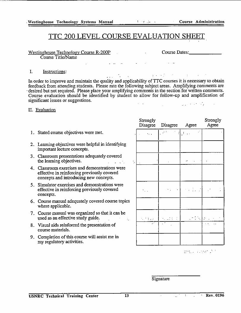
TTC 200 LEVEL COURSE EVALUATION SHEET
Westinghouse Technology Course R-200P Course Title/Name
Course Dates:
I. Instructions:
In order to improve and maintain the quality and applicability of TTC courses it is necessary to obtain feedback from attending students. Please rate the following subject areas. Amplifying comments are desired but not required. Please place your amplifying comments in the section for written comments. Course evaluation should be identified by student to allow for follow-up and amplification of significant issues or suggestions.
II. Evaluation
Strongly Disagree
1. Stated course objectives were met.
2. Learning objectives were helpful in identifying important lecture concepts.
3. Classroom presentations adequately covered the learning objectives.
4. Classroom exercises and demonstrations were effective in reinforcing previously covered concepts and introducing new concepts.
5. Simulator exercises and demonstrations were effective in reinforcing previously covered concepts.
6. Course manual adequately covered course topics where applicable.
7. Course manual was organized so that it can be used as an effective study guide.
8. Visual aids reinforced the presentation of course materials.
9. Completion of this course will assist me in my regulatory activities.
Disagree AgreeStrongly
Agree
Signature
USNRC Technical Training Center 13 Rev 0196
, Westinghouse Technology Systems Manual ICourse Administration
- Rev. 0196USNRC Technical Training Center 13
- Westinghouse Technolocy Systems MVanual
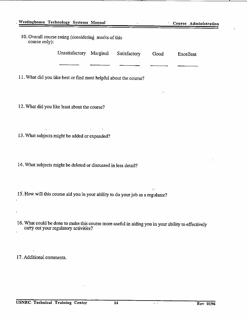
10. Overall course rating (6onsidering, merits of this course only):
Unsatisfactory Marginal Satisfactory
11. What did you like best or find most helpful about the course?
12. What did you like least about the course?
13. What subjects might be added or expanded?
14. What subjects might be deleted or discussed in less detail?
15. How will this course aid you in your ability to do your job as a regulator?
16. What could be done to make this course more useful in aiding you in your ability to effectively carry out your regulatory activities?
17. Additional comments.
USINI(C Technical Training Center 14 Rev 0196
Good Excellent
14 Rev 0196
Westinghouse Technology Systems Manual -&aý m n SLraLion
USNRCS, Technical Training Center
Westinghouse Technology Manual 100 Level Objectives
5.2 CONTAINMENT AND AUXILIARY SYSTEMS
Learning Objectives:
1. State the purpose of the containment building.
3. State the purpose of the containment hydrogen recombiners.
4. State the purpose of the containment fan coolers during accident and non-accident conditions.
5. State the purpose of the containment spray system.
6. Explain why sodium hydroxide is added to the containment spray.
Westinghouse Technology Manual 100 Level Objectives
5.3 AUXILIARY FEEDWATER SYSTEM
Learning Objectives:
1. State the purposes of the auxiliary feedwater system.
2. Describe the decay heat removal flowpath following a reactor trip under the following conditions:
a. With off-site power available and b. Without off-site power available.
3. List the suction sources for the auxiliary feedwater pumps and under what conditions each suction source is used.
Westinghouse Technology Manual 100 Level Objectives
5.4 COOLING WATER SYSTEMS
Learning Objectives:
1. Sate the purpose of the component cooling water system.
2. List two component cooling water system loads.
3. Explain how the component cooling water system is designed to prevent the release of radioactivity to the environment.
4. State the purpose of the service water system.
5. List two service water system loads.
6.0 ELECTRICAL SYSTEMS
Learning Objectives:
1. List the purposes of the plant electrical systems.
2. Explain how the plant electrical system is designed to ensure reliable operation of equipment important to safety with emphasis on the following:
a. Redundancy, b. Separation (physical and electrical), c. Reliable control power, d. Reliable instrumentation power, and e. Reliable AC power.
3. List the normal and emergency power sources to the vital (Class 1E) AC electrical distribution system.
4. State the purpose of the diesel generators.
6. Describe the automatic actions that occur in the electrical system following a plant trip and loss of off-site power.
100 Level ObjectivesWestinghouse Technology Manual
7.2 CONDENSATE AND FEEDWATER SYSTEM
Learning Objectives:
1. List the purposes of the condensate and feedwater system.
2. State the purpose of the components and penetrations in the Seismic Category I portion of the main feedwater system:
a. Main feedwater isolation valves, b. Auxiliary feedwater system penetrations, and c. Main feedwater check valves.
3. State the purpose of the following condensate and feedwater system components:
a. Main condenser, b. Hotwell, c. Condensate (or hotwell) pumps, d. Condensate demineralizers (polishers), e. Low pressure feedwater heaters, f. Main feedwater pumps, g. High pressure feedwater heaters, h. Feedwater control and bypass valves, and i. Steam generators.
Westinghouse Technology Manual 100 Level Objectives
Westinghouse Technology Manual 100 Level Objectives
8.0 ROD CONTROL SYSTEM
Learning Objectives:
1. State the purpose of the rod control system.
2. Briefly explain how each purpose is accomplished.
3. List the inputs into the automatic rod control system and the reason each input is necessary.
6. Describe both the individual (analog) and the group demand rod position indication.
Westinghouse Technology Manual 100 Level Objectives
9.0 EXCORE NUCLEAR INSTRUMENTATION
Learning Objectives:
1. List and state the purposes of the three ranges of excore nuclear instrumentation.
2. Concerning the excore nuclear instrumentation inputs into the reactor protection system:
a. List the reactor protection system inputs from the excore nuclear instrumentation and b. State the purpose of each input.
3. Explain how the excore nuclear instrumentation is capable of detecting both axial and radial power distribution.

Westinghouse Technology Manual 100 Level Objectives
11.1 STEAM GENERATOR WATER LEVEL CONTROL SYSTEM
Learning Objectives:
1. List the purpose of the steam generator water level control system.
2. Briefly explain how the purpose is accomplished.
3. List the reactor protection system inputs and turbine trip signals provided by the steam generator water level control instruments and the purpose of each.
4. List the inputs to the steam generator water level control system and the reason each input is necessary.
Westinghouse Technology Manual 100 Level Objectives
11.2 STEAM DUMP CONTROL SYSTEM
Learning Objectives:
1. List the purposes of the steam dump control system.
3. Describe how the system functions in:
a. Steam pressure mode and b. Tavg mode.
4. List the input signals to the steam dump control system.

12.0 REACTOR PROTECTION SYSTEM
Learning Objectives:
1. State the purpose of the reactor protection system.
2. Describe how the purpose of the reactor protection system is accomplished.
3. Explain and give an example of how each of the following is incorporated into the design of the reactor protection system:
a. Redundancy, b. Independence, c. Diversity, d. Fail safe, and f. Single failure criteria.
4. Given a list of reactor trips, explain the purpose of each.
5. State the purpose of the engineered safety features actuation system.
7. List each of the five engineered safety features actuation signals and the specific accident each is designed to handle.
Westinghouse Technology Manual 100 Level Objectives
Westinghouse Technology Manual 100 Level Objectives
17.0 PLANT OPERATIONS
Learning Objectives:
1. Arrange the following evolutions in the proper order for a plant startup from cold shutdown:
a. Start all reactor coolant pumps, b. Place all engineered safety systems in an operable mode, c. Establish no-load Tavg, d. Take the reactor critical, e. Start a main feedwater pump, f. Load main generator to the grid, and g. Place steam generator level control system in automatic.
1.1 REFERENCE DOCUMENTS
Learning Objectives
1. Identify the following reference documents giving a statement of their contents and/or functions:
a. Code of Federal Regulations (CFR), b. Final Safety Analysis Report (FSAR) c. Regulatory Guides (Reg. Guides), and d. Technical Specifications (Tech. Specs.).
2. Define the following terms as stated in the reference documents:
a. Design basis, b. Reactor coolant pressure boundary, c. Loss of coolant accident (LOCA), d. Single failure, and e. Seismic Category I.
200 Level Objectives
1.2 INTRODUCTION TO PRESSURIZED WATER REACTOR GENERATING
SYSTEMS
Learning Objectives:
1. Define the following terms:
a. Average reactor coolant system temperature (Tag),
b. Differential reactor coolant system temperature (AT), c. Departure from nucleate boiling (DNB), d. Departure from nucleate boiling ratio (DNBR), e. Power density (Kw/ft), and f. Seismic Category I.
2. Explain why Tavg is programmed to increase with an increasing plant load.
3. List two plant safety limits and explain the basis of each.
4. List, in flow path order, the major components in the:
a. Primary cycle and b. Secondary cycle.
200 Level Objectives
Westinahnoiqe Technoloqv Manual 20LvlOjcie
2.0 REACTOR PHYSICS
Learning Objectives:
1. Define the following terms:
a. Keff, b. Reactivity, c. Critical, d. Supercritical, e. Subcritical, f. Moderator temperature coefficient, g. Fuel temperature coefficient (Doppler), h. Void coefficient, i. Power coefficient, j. Power defect, and k. Neutron poison.
2. List two controllable and one uncontrollable neutron poison.
200 Level Objectives

Westinghouse Technology Manual 200 Level Objectives
3.1 REACTOR CORE AND VESSEL CONSTRUCTION
Learning Objectives:
1. State the purpose of the following major reactor vessel and core components:
a. Internals support ledge, b. Thermal shield, c. Secondary support assembly, d. Fuel assembly, e. Control rod, f. Upper and lower core support structures, g. Primary and secondary source assemblies, h. Burnable poison rod assemblies, and i. Thimble plug assemblies.
2. Describe the flow path of reactor coolant from the inlet nozzles to the outlet nozzles of the
reactor vessel.
3. List the basic structural components of a fuel assembly.

3.2 REACTOR COOLANT SYSTEM
Learning Objectives:
1. State the purpose of the reactor coolant system.
2. List in flow path order and state the purpose of the following major components of the reactor coolant system:
a. Reactor vessel, b. Steam generator, and c. Reactor coolant pump.
3. List and state the purpose of the following reactor coolant system penetrations:
a. Hot leg 1. Pressurizer surge line, 2. Resistance temperature detector, and 3. Residual heat removal system suction.
b. Intermediate (crossover) leg 1. Chemical and volume control system letdown connection and 2. Elbow flow taps.
c. Cold leg 1. Pressurizer spray line, 2. Resistance temperature detector, 3. Common emergency core cooling system connections for residual heat removal, safety
injection, and cold leg accumulators, 4. High head injection, and 5. Chemical and volume control system charging.
4. Describe the flow path through the steam generator for both the reactor coolant system and
steam side.
5. State the purpose of the following components of the reactor coolant pump:
a. Thermal barrier heat exchanger, b. Shaft seal package, c. Flywheel, and d. Anti-reverse rotation device.
6. State the purpose of the pressurizer and the following associated components:
a. Code safety valves, b. Power operated relief valves, c. Power operated relief valves block valves, d. Pressurizer relief tank, e. Pressurizer spray valves, and f. Pressurizer heaters.
200 Level Objectives
5.1 EMERGENCY CORE COOLING SYSTEMS
Learning Objectives:
1. Explain why emergency core cooling systems are incorporated into plant design.
2. Describe the operation of the emergency core cooling systems during the following conditions:
a. Injection phase and b. Recirculation phase.
3. State the purposes of the residual heat removal system.
4. Describe the residual heat removal system flow path, including suction supplies, discharge points, and major components during the following operations:
a. Decay heat removal, b. Injection phase, and c. Recirculation phase.
5. State the purposes of the following systems:
a. Accumulator injection system, b. Safety injection pump system, and c. High head injection system.
6. State the purpose of the following components:
a. Refueling water storage tank and b. Containment recirculation sump.
7. List the order of emergency core cooling systems injection during the following abnormal conditions:
a. Inadvertent actuation (at normal operating temperature and pressure), b. A small (slow depressurization of the reactor coolant system) break loss of coolant
accident, and c. A large loss of coolant accident.
8. List all engineered safety features actuation signals and the accident(s) for which each signal provides protection.
200 Level ObjectivesWestinghouse Technology Manual
5.2 CONTAINMENT AND AUXILIARY SYSTEMS
Learning Objectives:
1. State the purpose of the containment building.
2. State the purpose of containment isolation during an accident, including:
a. When isolation occurs, b. The types of systems isolated, and c. How redundancy of isolation is provided.
3. State the purpose of the containment hydrogen recombiners.
4. State the purpose of the containment fan coolers during accident and non-accident conditions.
5. State the purpose of the containment spray system.
6. Explain why sodium hydroxide is added to the containment spray.
7. List the containment spray system actuation signals.
200 Level Objectives

Westinghouse Technology Manual 200 Level Objectives
5.3 AUXILIARY FEEDWATER SYSTEM
Learning Objectives:
1. State the purposes of the auxiliary feedwater system.
2. Describe the decay heat removal flowpath following a reactor trip under the following conditions:
a. With off-site power available and b. Without off-site power available.
3. List the suction sources for the auxiliary feedwater pumps and under what conditions each suction source is used.
4. List three plant conditions that will result in an automatic start of the auxiliary feedwater system.
Westinghouse Technology Manual 200 Level Objectives
5.4 COOLING WATER SYSTEMS
Learning Objectives:
1. Sate the purpose of the component cooling water system.
2. List two component cooling water system loads.
3. Explain how the component cooling water system is designed to prevent the release of radioactivity to the environment.
4. State the purpose of the service water system.
5. List two service water system loads.
Westinghouse Technology Manual 200 Level Objectives
6.0 ELECTRICAL SYSTEMS
Learning Objectives:
1. List the purposes of the plant electrical systems.
2. Explain how the plant electrical system is designed to ensure reliable operation of equipment important to safety with emphasis on the following:
a. Redundancy, b. Separation (physical and electrical), c. Reliable control power, d. Reliable instrumentation power, and e. Reliable AC power.
3. List the normal and emergency power sources to the vital (Class 1E) AC electrical distribution system.
4. State the purpose of the diesel generators.
5. List the automatic start signals for the diesel generators and the condition that causes the closure of the diesel generator output breaker.
6. Describe the automatic actions that occur in the electrical system following a plant trip and loss of off-site power.
7. List four (4) typical loads powered by the vital 4160 volt buses.

Westinghouse Technology Manual
7.1 MAIN AND AUXILIARY STEAM SYSTEMS
Learning Objectives:
1. State the purposes of the main steam system.
2. Identify the portion of the main steam system that is Seismic Category I.
3. List in the proper flow path order and state the purpose of the components and connections located in the Seismic Category I portion of the main steam system:
a. Steam generator, b. Flow restrictor, c. Power operated relief valve, d. Code safety valves, e. Steam supply to auxiliary feedwater pump turbine, f. Main steam isolation valves, and g. Main steam check valves.
4. List in the proper flow path order and state the purpose of the following components associated with the main steam system:
a. Turbine throttle/governor valves, b. High pressure turbine, c. Moisture separator reheater, d. Turbine intercept/reheat stop valves, e. Low pressure turbine, and f. Condenser.
200 Level Objectives
200 Level Objectives
7.2 CONDENSATE AND FEEDWATER SYSTEM
Learning Objectives:
1. List the purposes of the condensate and feedwater system.
2. State the purpose of the components and penetrations in the Seismic Category I portion of the main feedwater system:
a. Main feedwater isolation valves, b. Auxiliary feedwater system penetrations, and c. Main feedwater check valves.
3. List in the proper flow path order and state the purpose of the following condensate and feedwater system components:
a. Main condenser, b. Hotwell, c. Condensate (or hotwell) pumps, d. Condensate demineralizers (polishers), e. Low pressure feedwater heaters, f. Main feedwater pumps, g. High pressure feedwater heaters, h. Feedwater control and bypass valves, and i. Steam generators.
4. State the sources of heat for the low pressure and high pressure feedwater heaters.

7.3 MAIN TURBINE, MOISTURE SEPARATOR REHEATERS, AND
ELETROHYDRAULIC CONTROL SYSTEM
Learning Objectives:
1. State the purposes of the main turbine.
2. State the purpose of the moisture separator reheaters.
3. State the purpose and function of extraction steam.
4. State the purposes of the electrohydraulic control system.
5. List the control signals used for the following turbine operational modes:
a. Speed control and b. Load control.
6. List the turbine trip inputs to the reactor protection system.
Westinghouse Technology Manual 200 Level Objectives
Westinghouse Technology Manual 200 Level Objectives
8.0 ROD CONTROL SYSTEM
Learning Objectives:
1. State the purpose of the rod control system.
2. Briefly explain how each purpose is accomplished.
3. List the inputs into the automatic rod control system and the reason each input is necessary.
4. Explain how failures in the system are prevented from affecting reactor trip capability.
5. State the purpose of the control rod drive mechanism and explain how it is designed to ensure reliable reactor trip capability.
6. Describe both the individual (analog and digital) and the group demand rod position indication.

Westinghouse Technology Manual 200 Level Objectives
9.0 EXCORE NUCLEAR INSTRUMENTATION
Learning Objectives:
1. List and state the purposes of the three ranges of excore nuclear instrumentation.
2. Concerning the excore nuclear instrumentation inputs into the reactor protection system:
a. List the reactor protection system inputs from the excore nuclear instrumentation, b. State the purpose of each input, and c. State whether each input can be blocked or bypassed.
3. Explain how the excore nuclear instrumentation is capable of detecting both axial and radial
power distribution.
4. Explain how the power range is calibrated to indicate percent of full power.
Westinghouse Technology Manual 200 Level Objectives
10.1 REACTOR COOLANT SYSTEM INSTRUMENTATION
Learning Objectives:
1. List three protection signals described in this chapter.
2. List two systems which respond to the auctioneered Tavg signal.
3. State the basis for the low flow reactor trip.
4. State the basis for the OTAT and OPAT trips.
Westinghouse Technology Manual 200 Level Objectives
10.2 PRESSURIZER PRESSURE CONTROL SYSTEM
Learning Objectives:
1. State the purpose of the pressurizer pressure control system.
2. List all pressurizer pressure inputs to the reactor protection system and state the purpose of each input.
3. List in order the devices or trips that would actuate to limit or control pressure as reactor coolant system pressure increases from normal system pressure to design system pressure of 2485 psig.
4. List in order the devices or trips that would actuate to limit or control pressure as reactor coolant system pressure is decreased from its normal pressure of 2235 psig.

Westinghouse Technology Manual 200 Level Objectives
10.3 PRESSURIZER LEVEL CONTROL SYSTEM
Learning Objectives:
1. State the purpose of the pressurizer level control system.
2. State the purpose of the pressurizer level input to the reactor protection system.
3. Identify the signal that is used to generate the "reference level" and explainr why level is programmed.
4. Describe the components used to change charging flow in response to level error signals.
5. State the purpose and describe the function of the pressurizer low level interlock.

Westinghouse Technology Manual 200 Level Objectives
11.1 STEAM GENERATOR WATER LEVEL CONTROL SYSTEM
Learning Objectives:
1. List the purpose of the steam generator water level control system.
2. Briefly explain how the purpose is accomplished.
3. List the reactor protection system inputs and turbine trip signals provided by the steam generator water level control instruments and the purpose of each.
4. List the inputs to the steam generator water level control system and the reason each input is necessary.
5. Describe why feed pump speed is programmed.
Westinghouse Technology Manual 200 Level Objectives
11.2 STEAM DUMP CONTROL SYSTEM
Learning Objectives:
1. List the purposes of the steam dump system.
2. Briefly explain how each purpose is accomplished.
3. Describe how the system functions in:
a. Steam pressure mode and b. Tavg mode.
4. List the input signals to the steam dump control system.
5. List the "arming" and "interlocking" signals.
12.0 REACTOR PROTECTION SYSTEM
Learning Objectives:
1. State the purpose of the reactor protection system.
2. Describe how the purpose of the reactor protection system is accomplished.
3. Explain and give an example of how each of the following is incorporated into the design of the reactor protection system:
a. Redundancy, b. Independence, c. Diversity, d. Fail safe, e. Testability, and f. Single failure criteria.
4. Given a list of reactor trips, explain the purpose of each.
5. State the purpose of the engineered safety features actuation system.
6. Describe how the purpose of the engineered safety features actuation system is accomplished.
7. List each of the five engineered safety features actuation signals and the specific accident each is designed to handle.
8. List the systems or equipment which are actuated or tripped upon the receipt of an engineered safety features actuation signal.
Westinghouse Technology Manual 200 Level Objectives
14.0 REFUELING SYSTEMS
Learning Objectives:
1. State the functions of each of the following fuel handling system equipment:
a. Spent fuel pool bridge crane, b. New fuel elevator, c. Fuel transfer canal, d. Manipulator crane, e. Rod cluster control assembly change fixture, f. Reactor vessel stud tensioner, g. Conveyor car, and h. Upenders.
2. State the reasons for handling spent fuel under water.
3. State the purpose of the spent fuel pit cooling system.
Westinghouse Technology Manual 200 Level Objectives
Westinghouse Technology Manual 200 Level Objectives
15.0 RADIOACTIVE WASTE DISPOSAL SYSTEMS
Learning Objectives:
1. State the purpose of each of the following radioactive waste processing systems:
a. Liquid radioactive waste processing system, b. Solid radioactive waste processing system, and c. Gaseous radioactive waste processing system.
2. Concerning the liquid radioactive waste processing system:
a. Explain why liquid radioactive waste is separated into reactor grade and non-reactor grade waste,
b. List two inputs into the reactor grade waste subsystem, and c. Describe four methods of processing liquid radioactive wastes.
3. Concerning the solid radioactive waste processing system:
a. List the two categories of solid radioactive waste and b. List two contributors to solid radioactive waste.
4. Concerning the gaseous radioactive waste processing system:
a. List the principle volume contributors to the gaseous radioactive waste system and b. List two major radioisotope contributors to the gaseous radioactive waste system.
16.0 RADIATION MONITORING SYSTEM
Learning Objectives:
1. List three functions of the radiation monitoring system.
2. List the two subsystems of the radiation monitoring system.
3. State the purpose of the area radiation monitoring system.
4. State the functions of the following components used in the area radiation monitoring system:
a. Detectors, b. Electronics channel, and c. Remote indicator.
5. State the function of the liquid process monitoring system.
6. State the function of the liquid effluent monitoring system.
7. State the function of the airborne process monitoring system.
8. State the function of the airborne effluent monitoring system.
200 Level Objectives

Westinghouse Technology Manual 200 Level Objectives
17.0 PLANT OPERATIONS
Learning Objectives:
1. Arrange the following evolutions in the proper order for a plant startup from cold shutdown:
a. Start all reactor coolant pumps, b. Place all engineered safety systems in an operable mode, c. Establish no-load Tavg, d. Take the reactor critical, e. Start a main feedwater pump, f. Load main generator to the grid, and g. Place steam generator level control system in automatic.
Westinghouse Technology Manual Contents
CHAPTER
1.1 REFERENCE DOCUMENTS 1.1.1 Introduction ..................................... 1.1.2 Code of Federal Regulations ......................... 1.1.3 Final Safety Analysis Report ......................... 1.1.4 Technical Specifications ............................ 1.1.5 Codes and Standards.............................. 1.1.6 Regulatory Guides ............................... 1.1.7 Summary .....................................
1.2 INTRODUCTION TO PWR SYSTEMS 1.2.1 General Description ............................... 1.2.2 Plant Layout ................................... 1.2.3 Reactor Coolant System Pressure and Pressurizer Level Control 1.2.4 ReactorControl ...... ...................... : .... 1.2.5 Plant Safety Limits ............................... 1.2.6 Summ ary .....................................
1.3 INSTRUMENTATION AND CONTROL 1.3.1 Introduction ......................... ........... 1.3.2 Pressure Sensing Instruments......................... 1.3.3 Flow Sensing Instruments .......................... . 1.3.4 Level Sensing Instruments........................... 1.3.5 Temperature Sensing Instruments ...................... 1.3.6 Mechanical to Electrical Signal Conversion ....... ....... 1.3.7 Controllers and Signal Conditioning ................... 1.3.8 Logic Diagrams ................................. 1.3.9 Electrical Relay .................................
2.0 REACTOR PHYSICS n V1 : n_/. I ss~ldl on ce,!• s ............................. ........
2.2 Neutron Multiplication................................. 2.3 Reactivity and Reactivity Coefficients ....................... 2.4 Neutron Poisons ........ ........................... 2.5 Shutdown M argin ...................................
'3.1 REACTOR CORE AND VESSEL CONSTRUCTION 3.1.1 Introduction ...... ...................... I........... 3.1.2 Reactor .......................................... . 3.1.3 Summary ..........................................
3.2 REACTOR COOLANT SYSTEM 3.2.1 Introduction ...................................... 3.2.2 General Description ........................ ...... ... 3.2.3 Component Description ................................ 3.2.4 Reactor Coolant Pump Seals ............................
2-1 2-1 2-2 2-4 2-4
3.1-1 ... 3.1-1 ... 3.1-6
... 3.2-1
... 3.2-2
... 3.2-2
... 3.2-5
USNRC Technical Training Center C-i 0698
Page
1.1-1 1.1-3 1.1-3 1.1-3 1.1-4
•1.1-7
1.2-1 1.2-3 1.2-3
"1.2-4 1.2-5 1.2-8
1.3-1 1.3-1 1.3-2 1.3-3 1.3-4 1.3-5 1.3-6
1.3-10 1.3-11
0698
ýWestinghouse Technology Manual •- I Contents
USNRC Technical Training Center C-1

4.0 CHEMICAL AND VOLUME CONTROL SYSTEM 4.1 Introduction . ............................................ 4-1 4.2 Functional Description ..................................... 4-2 4.3 Detailed Description . ...................................... 4-2 4.4 Reactor Coolant Pump Seals . ................................ 4-6 4.5 Reactor Makeup System . ................................... 4-6 4.6 Engineered Safety Features . ................................. 4-8 4.7 Boron Recycle System . .................................... 4-8
5.1 EMERGENCY CORE COOLING SYSTEMS 5.1.1 Introduction . .......................................... 5.1-1 5.1.2 System Description . ..................................... 5.1-2 5.1.3 Operations ............................................ 5.1-6 5.1.4 Summ ary ........ : ................................... 5.1-8
5.2 CONTAINMENT AND AUXILIARY SYSTEMS 5.2.1 Introduction . .......................................... 5.2-1 5.2.2 Containment .......................................... . 5.2-1 5.2.3 Containment Heat Removal Systems ........................... 5.2-3 5.2.4 Containment Cooling System ................................ 5.2-4 5.2.5 Containment Spray System . ................................ 5.2-7 5.2.6 Containment Isolation ..................................... 5.2-9 5.2.7 Containment Combustible Gas Control System'................... 5.2-10 5.2.8 Fission Product Removal and Control Systems .................. 5.2-12 5.2.9 Containment Hydrogen Control System ........................ 5.2-13 5.2.10 Containment Atmosphere Control System ....................... 5.2-13 5.2.11 Containment Purge System . ............................... 5.2-14 5.2.12 Summ ary . ........................................... 5.2-14
5.3 AUXILIARY FEEDWATER SYSTEM 5.3.1 Introduction ........................................... 5.3-1 5.3.2 System Description . ..................................... 5.3-1 5.3.3 Component Description ................................... 5.3-2 5.3.4 Operations . ........................................... 5.3-3 5.3.5 Summ ary . ............................................ 5.3-3
5.4 COOLING WATER SYSTEMS 5.4.1 Component C6oling Water System ........................... 5.4-1 5.4.2 Service Water System ..................................... 5.4-2 5.4.3 Circulating Water System . ................................. 5.4-2
6.0 ELECTRICAL SYSTEMS 6.1 Introduction ............................................ 6-1 6.2 System Description ...................................... 6-1 6.3 Component Description . .................................... 6-2 6.4 Summ ary . ............................................. 6-4
7.1 MAIN AND AUXILIARY STEAM SYSTEMS 7.1.1 Introduction . .......................................... 7.1-1 7.1.2 M ain Steam . ........................................... 7.1-1 7.1.3 Auxiliary Steam ......................................... 7.1-4
Westinghouse Technology Manual Contents
USNRC Technical Training Center C-2 0698

Westinghouse Technology Manual Contents
7.2 CONDENSATE AND FEEDWATER SYSTEM'7.2.1 Introduction .. .......................................... 7.2-1 7.2.2 Condensate System ........................................ 7.2-1 7.2.3 Feedwater System ....................................... 7.2-3
7.3 MAIN TURBINE, MSR, AND EHC 7.3.1 Introduction..............7.3-1 7.3.2 Main Turbine .......................................... 7.3-1 7.3.3 Electrohydraulic Control System .............................. 7.3-3 7.3.4 Moisture Separator Reheaters ................................ 7.3-4 7.3.5 Summary . ............................................ 7.3-5
8.0 ROD CONTROL SYSTEM 8.1 Introduction . ............................... ........... 8-1 8.2 System Description...................................8-1 8.3 System Operation ...................... : ................... 8-3 8.4 Mechanism Description ....................................... 8-6 8.5 Rod Position Indication ...................................... 8-6
8.6 Summary .................. ............................ 8-8
9.0 EXCORE NUCLEAR INSTRUMENTATION 9.1 Introduction .. .......................................... 9-1 9.2 Source Range..........................9-2 9.3 Intermediate Range .......................................... 9-3 9.4 Power Range ..... ....................................... 9-4
9.5 Summary ............................................... 9-6
10.1 REACTOR COOLANT SYSTEM INSTRUMENTATION 10.1.1 Overview . ........................................... 10.1-1 10.1.2 Resistance Temperature Detector Operation ....... :..... ... :........10.1-1 10.1.3 RCS Flow Instrument........ .......................... 10.1-2 10.1.4 Inputs to the Reactor Protection System .......................... 10.1-3 10.1.5 Inputs to Reactor Control Systems ........................... 10.1-4 10.1.6 Temperature Alarmsuts tRetro . ............................ .10.1-4
10.1.7 Summary .............................................. 10.1-5
10.2 PRESSURIZER PRESSURE CONTROL 10.2.1 Introduction ..................................... ........ 10.2-1 10.2.2 System Design and Operation .............. :............. •.....10.2-1 10.2.3 Summary .. ............................... ............ 10.2-3
10.3 PRESSURIZER LEVEL CONTROL-';, 10.3.1 Introduction ............................ .............. 10.3-1
.10.3.2 System Design and Operation.....................10.3-1
10.3.3 Summary ..............-................. 10.3-2
11.1 STEAM GENERATOR WATER LEVEL CONTROL SYSTEM 11.1.1 Introduction ..... ..................................... 11.1-1 11.1.2 System Description :.................. .................. 11'.1-1 11.1.3 Feed Pump Speed Control ........................... ...... 11.1-3 11.1.4 Summary .. ........................................... 11.1-3
USNRC Technical Training Center ' , C-3 .' 0698
Westinghouse Technology Manual Contents
11.2 STEAM DUMP CONTROL SYSTEM, 11.2.1 Introduction .......................... 11.2.2 System Description ..................... 11.2.3 Steam Dump Operations .................. 11.2.4 Summ ary ............................
12.0 REACTOR PROTECTION SYSTEM 12.1 Introduction ..................... 12.2 Reactor Protection System Design ..... 12.3 System Description ............... 12.4 Summary ......................
13.0 PLANT AIR SYSTEMS 13.1 Introduction ...................................... 13.2 System Description ................................ 13.3 Component Description .............................. 13.4 System Interrelationships ............................ 13.5 Summ ary .......................................
14.0 REFUELING SYSTEMS 14.1 Introduction ....................................... 14.2 Fuel Handling Facilities ............................. 14.3 Refueling Equipment ............................... 14.4 Refueling Operation ................................ 14.5 New Fuel Handling ................................. 14.6 Common Refueling Equipment Modifications ............... 14.7 Reactor Cavity Filtration System ........................ 14.8 Spent Fuel Pit Cooling System .........................
15.0 RADIOACTIVE WASTE DISPOSAL SYSTEMS 15.1 Introduction............................ 15.2 Liquid W aste Processing ............................. 15.3 Solid Waste Processing ............................... 15.4 Gaseous Waste Processing ........................... 15.5 Summ ary .......................................
16.0 RADIATION MONITORING SYSTEM 16.1 Introduction .... :. .- ................................ 16.2 Area Monitoring System.............................. 16.3 Process Monitoring System ........................... 16.4 Summ ary .......................................
17.0 PLANT OPERATIONS 17.1 Introduction ...................... 17.2 Plant Heatup ...................... 17.3 Reactor Startup to Minimum Load ....... 17.4 Power Operations .................. 17.5 Plant Shutdown...................
.... oo.......o°......
................... o..
............ ~oo.....
.. °..........o°°....
18.0 OVERVIEW AND COMPARISON OF U. S. COMMERCIAL NUCLEAR POWER PLANTS
Westinghouse Technology Manual •.. Contents
11.2-1 11.2-1 11.2-3 11.2-4
12-1 12-1 12-3 12-9
13-1 13-1 13-2 13-3 13-4
14-1 14-1 14-3 14-7
14-11 14-12 14-13 14-13
15-1 15-1 15-4 15-4 15-6
16-1 16-1 16-3 16-4
17-1 17-1 17-3 17-4
-17-5...................
...................
USN•RC Technical Training Center C-°4 0698
Wes~tina'hnnse Technolopv Manual Cnet
19.0 COMBUSTION ENGINEERING PLANT 19.1 Introduction ........................ 19.2 Mechanical Systems ................... 19.3 Plant Protection and Monitoring Systems ..... 19.4 Summary ..........................
20.0 BABCOCK & WILCOX PLANT 20.1 Introduction ................ 20.2 Mechanical Systems ........... 20.3 Control Systems ............. 20.4 Summary ..................
DESCRIPTION ................
............ °...
S. . . . . . .. . . . . .° . °..
.... °.°.........
DESCRIPTION .°..............
.. °.,...........
............ o...
...............
1'. d nO �Jo y 0USNRC Technical Training Center
19-1 19-1 19-2 19-3
20-1 20-1 20-3 20-4
C-°5
Contents
U 13 Dp 0
Westinghouse 'Technology Manual List of Figures
CHAPTER .Pa-p_.
1.1 REFERENCE DOCUMENTS 1.1-1 Reference Documents .......... .......................... 1.1-9 1.1-2 Code of Federal Regulations ................. ............... 1.1-11 1.1-3 Title, Chapter, Part .............. ............... . ....... 1.1-13 1.1-4 Title 10, Table of Contents . ................................ 1.1-15 1.1-4a Title 10, Table of Contents (continued) ... ..................... 1.1-17 1.1-5 10CFR50 Definitions . ................................... 1.1-19 1.1-6 10CFR50 Requirements . ................................. 1.1-21 1.1-7 Final Safety Analysis Report ...................... I ........ 1.1-23 1.1-8 Technical Specifications . ................................. 1.1-25 1.1-9 Codes and Standards .......... . .................. ...... 1.1-27 1.1-10 Regulatory Guides ........................ ...... ... 1.1-29 1.1-11 1OCFR100 ............................................ 1.1-31
1.2- INTRODUCTION TO PWR SYSTEMS,-, 1.2-1 Plant Systems Composite .................................. 1.2-9 1.2-2 Plant Layout ............................. ................ 1.2-11 1.2-3 Basic PWR Arrangement ......... ...... ....... ......... 1.2-13 1.2-4 Characteristics of a Constant Average TemperatureProgram .......... 1.2-15 1.2-5 Characteristics of a Constant Steam Pressure Program ............. 1.2-17 1.2-6 Characteristics of a Sliding Average Temperature Program ... ,...... 1.2-19 1.2-7 Departure from Nucleate Boiling ............................. 1.2-21 1.2-8 List of Symbols ... ...................................... 1.2-23
1.3 INSTRUMENTATION AND CONTROL 1.3-1 -Simple Bourdon Tube ............................ ....... 1.3-13 1.3-2 Wound Pressure Detectors .............................. . 1.3-15
"1.3-3 Sealed Pressure Detectors .................................. 1.3-17 1.3-4 Primary Devices .. ...................................... 1.3-19 1.3-5 Bellows Flow Sensor ............. ................... 1.3-21 1.3-6 Diaphragm Flow Sensor ..................................... 13-23 1.3-7 Magnetic Flow Sensor ..................................... 1.3-25 1.3-8 Direct Level Measurement Devices _............... 1.3-27
1.3-9 Differential Pressure Level Detector ........... ................. 1.3-29 1.3-10 Reference Leg Differential Pressure System ...................... 1.3-31 1.3-11 Variable Capacitance Differential Pressure Sensor .................. 1.3-33 1.3-12 Fluid-Filled Temperature Sensor .............................. 1.3-35 1.3-13 Thermocouple ...... ........ •........................1.3-37 1.3-14 Resistance Temperature Detector ............................ 1.3-39 1.3-15 Force Balance Transmitters ................................... 1.3-41 1.3-16 Movable Core Transmitters . .' .-. ..-.... . 1.3-43 1.3-17 Variable Capacitance Transmitters .... ...... ............. 1.3-45 1.3-18 Basic Control Diagram ................................... 1.3-47 1.3-19 Proportional Controller .... .................. 1.3-49
1.3-20 Proportional Plus Integral Controller ..... '......... ..... 1.3-51
1.3-21 Time Constant .............................. ..... 1.3-53 1.3-22 Proportional Plus Integral Plus Derivative Controller . .-. :. '....... 1.3-55 1.3-23 PID Controller Responses . ................................ 1.3-57 1.3-24 Manual/Auto Control Stations . ............................. 1.3-59 1.3-25 Signal Conditioning Output with Varying Time Constants ........... 1.3-61
U070USNRC Technical Training Center ý F-1
1.3 INSTRUMENTATION AND CONTROL (cont) 1.3-26 Logic Functions . ....................................... 1.3-63 1.3-27 Relay . .............................................. 1.3-65
2.0 REACTOR PHYSICS 2-1 Moderator Temperature Coefficient ............................. 2-7 2-2 Doppler Temperature Coefficient . ............................. 2-9 2-3 Power Coefficient .. ...................................... 2-11 2-4 Power Defect .. ......................................... 2-13 2-5 Differential and Integral Rod Worth ............................ 2-15 2-6 Xenon Transients . ....................................... 2-17
3.1 REACTOR CORE AND VESSEL CONSTRUCTION 3.1-1 Reactor Vessel Supports . .................................. 3.1-7 3.1-2 Reactor Vessel Cross Section ................................ 3.1-9 3.1-3 Core and Vessel Outline ................................. 3.1-11 3.1-4 Reactor Vessel Internals .................................. 3.1-13 3.1-5 Lower Core Support Structure . ............................. 3.1-15 3.1-6 Core Flow Paths . ...................................... 3.1-17 3.1-7 Upper Core Support Structure .............................. 3.1-19 3.1-8 Fuel Loading Pattern . ................................... 3.1-21 3.1-9 Cutaway of Typical Fuel Assembly with Control Rod ............. 3.1-23 3.1 - 10 Fuel Assembly with Control Rod Inserted . ..................... 3.1-25 3.1-11 Spring Clip Grid Assembly . ............................... 3.1-27 3.1-12 Full Length Control Rod . ................................. 3.1-29 3.1-13 Thimble Plug Assembly . ................................. 3.1-31 3.1-14 Burnable Poison Assembly ................................ 3.1-33 3.1-15 Primary Source Assembly ................................ 3.1-35 3.1-16 Secondary Source Assembly . .............................. 3.1-37 3.1-17 Magnetic Jack Assembly . ................................. 3.1-39
3.2 REACTOR COOLANT SYSTEM 3.2-1 Reactor Coolant System (Elevation View) . ...................... 3.2-7 3.2-2 Reactor Coolant System . .................................. 3.2-9 3.2-3 Pressurizer . .......................................... 3.2-11 3.2-4 Steam Generator Flow Paths . .............................. 3.2-13 3.2-5 Reactor Coolant Pump . .................................. 3.2-15 3.2-6 Reactor Coolant Pump Seal . ............................... 3.2-17 3.2-7 Reactor Coolant Loop Penetrations .......................... 3.2-19 3.2-8 Reactor Coolant Pump Flywheel and Anti-Reverse Rotation Device .... 3.2-21
4.0. CHEMICAL AND VOLUME CONTROL SYSTEM 4-1 Chemical and Volume Control System Functional Diagram ............ 4-9 4-2 Chemical and Volume Control System .......................... 4-11 4-3 Chemical and Volume Control System Flow Balance ............... 4-13 4-4 Reactor Coolant Pump'Seal . ................................ 4-15 4-5 Reactor Makeup System . .................................. 4-17 4-6 Boron Recycle System . ................................... 4-19
USNRC Technical Training Center F-2 0698
Westinghouse Technology Manual List of Figures
F-2USNRC Technical Training Center 0698

5.1 EMERGENCY CORE COOLING SYSTEMS 5.1-1 Emergency Core Cooling Systems (Simplified Composite) ........... 5.1-9 5.1-2 Residual Heat Removal System ............................. 5.1-11 5.1-3 Containment Recirculation Sump ............................ 5.1-13 5.1-4 Cold Leg Accumulator System .............................. 5.1-15 5.1-5 Safety Injection System ............ I ................. ........ 5.1-17 5.1-6 High Head Injection System ................... 5.1-19 5.1-7 ESF Actuation Logic ................................... 5.1-21 5.1-8 Slow RCS Depressurization (SBLOCA) ....................... 5.1-23
5.2 CONTAINMENT AND AUXILIARY SYSTEMS 5.2-1 Typical Site Layout .................................... 5.2-17 5.2-2 Containment Building Outline ............................... 5.2-19 5.2-3 Personnel Access Hatch . ................................. 5.2-21 5.2-4 Fuel Transfer Tube ........................ ................ 5.2-23 5.2-5 Containment Cooling ...................................... 5.2-25 5.2-6 Containment Spray ...................................... 5.2-27 5.2-7 Spray Header Arrangement ................................ 5.2-29 5.2-8 Containment Recirculation Sump ........................... 5.2-31 5.2-9 Electric Hydrogen Recombiner .............................. 5.2-33 5.2-10 Containment Atmosphere Control System ...... 5.2-35
5.3 AUXILIARY FEEDWATER SYSTEM 5.3-1- -Auxiliary Feedwater System .- ................... .. 5.3-5
5.4 COOLING WATER SYSTEMS 5.4-1 Component Cooling Water System .................. ......... 5.4-5 5.4-2 Service Water System .................................... ... 5.4-7 5.4-3 Condenser Circulating Water System ............................ 5.4-9
6.0 ELECTRICAL SYSTEMS 6-1 Typical Power Station Electrical Diagram ............ ............... 6-5
7.1 MAIN AND AUXILIARYSTEAM SYSTEMS 7.1-1 Main Steam System - High Pressure ............................ 7.1-5 7.1-2 Main Steam System - Low Pressure ......... ,.............. 7.1-7 7.1-3 Flow Restrictor (Two Types).................................. 7.1-9
7.2 CONDENSATE AND FEEDWATER SYSTEM 7.2-1 Feed and Condensate System .. .2. ;. .. .......... 7.2-5 7.2-2 Condensate System ................... .. 2-7 7.2-3 Condenser . ........................................... 7.2-9 7.2-4 Feedwater Heater "............... ...... 7.2-11 7.2-5 Feedwater System ................ ....................... 7.2-13
'7.3 MAIN TURBINE, MSR, AND EHC 7.3-1. Turbine-Generator ....................................... 7.3-7 7.3-2 Electrohydraulic Control System ............................. 7.3-9 7.3-3 Speed Control Functional Diagram ........................... 7.3-11 7.3-4 Load Control Functional Diagram ........................... 7.3-13
USNRC Technical Training Center F-3 ]369S--0698
Westinghouse Technology Manual List of Figures
I USNRC Technical Training CenterJ
SF-3
7.3 MAIN TURBINE, MSR, AND EHC (cont) 7.3-5 Moisture Separator Reheater . .............................. 7.3-15 7.3-6 Reheat Steam and Moisture Separators ......................... 7.3-17 7.3-7 Electrohydraulic and Auto Stop Oil Systems .................... 7.3-19
8.0 ROD CONTROL SYSTEM 8.1 Rod Control System Block Diagram . ......................... 5.1-11 8.2 Programmed Tavg - Resulting Parameters ..................... 5.1-13 8.3 Rod Speed Program . .................................... 5.1-15 8.4 Magnetic Jack Assembly .................................. 5.1-17 8.5 Rod Position Indication System . ............................ 5.1-19 8.6 Digital Rod Position Indication ............................. 5.1-21 8.7 DRPI Control Board Indication ............................ 5.1-23
9.0 EXCORE NUCLEAR INSTRUMENTATION 9-1 Neutron Detectors Range of Operation .......................... 9-7 9-2 Detector Locations . ....................................... 9-9 9-3 Source Range Detector ..................................... 9-11 9-4 Intermediate Range Detector ................................. 9-13 9-5 Power Range Detector ................................... 9-15 9-6 Source and Intermediate Range Block Diagrams .................. 9-17 9-7 Power Range Channel ........................................ 9-19
10.1 REACTOR COOLANT SYSTEM INSTRUMENTATION 10.1-1 Resistance Temperature Detector ............................ 10.1-7 10.1-2 Reactor Coolant Loop Instrumentation ......................... 10.1-9 10.1-3 Reactor Coolant System Average Temperature Instrumentation ...... 10.1-11 10.1-4 Reactor Coolant System AT Instrumentation .................... 10.1-13 10.1-5 Reactor Coolant System Auctioneered High Tavg ................. 10.1-15
10.2 PRESSURIZER PRESSURE CONTROL 10.2-1 Pressurizer Pressure Control . .............................. 10.2-5 10.2-2 Reactor Coolant System Pressure Setpoint Diagram ................. 10.2-7
10.3 PRESSURIZER LEVEL CONTROL 10.3-1 Pressurizer Level Control . ................................ 10.3-5 10.3-2 Pressurizer Level Program ................................ 10.3-7
11.1 STEAM GENERATOR. WATER -LEVEL CONTROL SYSTEM 11.1 -1 Steam Generator Water Level Control System .................... 11.1-5 11.1-2 Feed Pump Speed Control . ................................ 11.1-5
11.2 STEAM DUMP CONTROL SYSTEM 11.2-1 Steam Dump Control (Simplified) ............................ 11.2-7 11.2-2 Steam Dump Control System ............................... 11.2-9 11.2-3 Steam Pressure Control Mode . ............................ 11.2-11 11.2-4 Tavg Control Mode ...................................... 11.2-13
USNRC Technical Training Center F-4 0698
Westinghouse Technology Manual List of' Figures
USNRC Technical Training Center F-4 0698

12.0 -REACTOR PROTECTION SYSTEM -12-1 Reactor Protection System ........ ....................... 12-21 12-2 Reactor Protection System Block Diagram.. ........... ....... 12-23 12-3 Overtemperature T Channel Block Diagram ..................... 12-25 12-4 Overpower T Channel Block Diagram ......................... 12-27 12-5 At Power Reactor Trip Logic .............................. 12-29 12-6 Engineered Safety Features Actuation Logic ...................... 12-31 12-7 Low Pressurizer Pressure ESF Actuation Logic .................. 12-33 12-8 High Steamline Flow ESF Actuation Logic ..................... 12-35 12-9 Steamline High Differential Pressure ESF Actuation Logic ............ 12-37 12-10 High Containment Pressure ESF Actuation Logic ................ 12-39
13.0 PLANT AIR SYSTEMS 13-1 Typical Air System ........................................ 13-7 13-2 Nitrogen Accumulator Backup Supply-.............................. 13-9
14.0 REFUELING SYSTEMS 14-1 Containment Building . ................................... 14-15 14-2 Fuel Transfer System .. ................................... 14-17 14-3 Permanent Cavity Seal Ring ............................... 14-19 14-4 Dual Basket Fuel Transfer Car . ............................. 14-21 14-5 Fuel Handling Tools . .................................... 14-23 14-6 Spent Fuel Pit Cooling and Purification System .................. 14-25
15.0 RADIOACTIVE WASTE DISPOSAL SYSTEMS 15-1 Liquid Waste Processing System . ............................ 15-7 15-2 Radwaste Volume Reduction System .......................... 15-9 15-3 Cement Solidification System .............................. 15-11 15-4 W aste Gas System .. ..................................... 15-13
16.0 RADIATION MONITORING SYSTEM 16-1 Geiger-Mueller Tube .. .................................... 16-9 16-2 Scintillation Detector . .................................... 16-11 16-3 Area Radiation Monitor Meter .. ............................. 16-13 16-4 Radiation Monitor Locations .. .............................. 16-15
17.0 PLANT OPERATIONS 17-1 Solid Plant Operations .. .................................. 17-11 17-2 Control Bank Insertion Limits for 4-Loop Operation .............. 17-13
18.0 OVERVIEW AND COMPARISON OF U. S. COMMERCIAL NUCLEAR POWER PLANTS
19.0 COMBUSTION ENGINEERING PLANT DESCRIPTION 19-1 Reactor Coolant System - Elevation View ....................... 19-5 19-2 Reactor Coolant System - Plan View ........................... 19-7 19-3 Steam Generator Secondary Side .. ............................ 19-9 19-4 Emergency Core Cooling Systems .. .......................... 19-11 19-5 Full Length CEA .. ...................................... 19-13 19-6 Control Element Drive Mechanism .. .......................... 19-15 19-7 Simplified Reactor Protection System . ........................ 19-17
0698
Westinghouse Technology Manual IIList of Figures
USNRC Technical Training Center F-5
19.0 COMBUSTION ENGINEERING PLANT DESCRIPTION (cont) 19-8 Coincidence Logic Matrix AB .. ............................. 19-19 19-9 CPC Software Block Diagram . ............................. 19-21 19-10 Core Operating Limits Supervisory System Block Diagram .......... 19-23
20.0 BABCOCK & WILCOX PLANT DESCRIPTION 20-1 Babcock & Wilcox Reactor Coolant System . ....................... 20-5 20-2 Cutaway View of B&W Once Through Steam Generator ............ 20-7 20-3 Once Through Steam Generator Heat Transfer Regime. .............. 20-9 20-4 High Pressure Emergency Core Cooling System ................. 20-11 20-5 Decay Heat Removal System ............................... 20-13 20-6 Core Flood Tanks ....................................... 20-15 20-7 Control Rod Drive Mechanism .............................. 20-17 20-8 Integrated Control System (Simplified) . ....................... 20-19 20-9 integrated Control System (Detailed) ......................... 20-21 20-10 Reactor Protection System Channel Logic ...................... 20-23
USNRC Technical Training Center F-6 0698
Westinghouse_ Technology Manual List of Fi•nre•
USNRC Technical Training Center F-6 0698

Westinghouse Technology Manual
Section 1.1
Reference Documents

Westinghouse Technology Manual Reference Documents
TABLE: OF CONTENTS
1.1 REFERENCE DOCUMENTS ........................................
1.1.1 Introduction ...............................................
1.1.2 Code of Federal Regulations ............................. ........
1.1.3 Final Safety Analysis Report (FSAR) ................................
1.1.4 Technical Specifications ........................................
1.1.5 Codes and Standards ......................................... 1.1.5.1 American National Standards Institute (ANSI) Standards .......... 1.1.5.2 American Society of Mechanical Engineers (ASME) Code ......... 1.1.5.3 Institute of Electrical and Electronic Engineers (IEEE) Standards .....
1.1.6 Regulatory Guides ...........................................
1.1.7 Sum m ary .................................................
LIST OF FIGURES
1.1-1 Reference Documents ............................................1.1-2 Code of Federal Regulations .............................. 1.1-3 Title, Chapter, Part .................................... 1.1-4 Title 10, Table of Contents ............................... 1.1-4a Title 10, Table of Contents (continued) .......................
1.1-5 10CFR50 Definitions ................................... 1.1-6 10CFR50 Requirements ................................. 1.1-7 Final Safety Analysis Report .............................. 1.1-8 Technical Specifications ................................. 1.1-9 Codes and Standards ................................... 1.1-10 Regulatory Guides ..................................... 1.1-11 10CFR100 ..........................................
ATTACHMENT A
10 CFR part 50.34 Contents of application; technical information ......... 10 CFR part 50.35 Technical specifications ....................... Facility Operating License ..................................... Technical specification 3/4.4.3 ..................................
USNRC Technical Training Center 1.1-i Key U1Y�
1.1-1
1.1-1
1.1-1
1.1-3
1.1-3
1.1-4 1.1-4 1.1-5 1.1-6
1.1-6
1.1-7
1.1-9 1.1-11 1.1-13 1.1-15 1.1-17 1.1-19 1.1-21 1.1-23 1.1-25 1.1-27 1.1-29 1.1-31
A-1 A-5 A-8
A-10
Westinghouse Technology Manual Reference Documents
I , ev 01518USNRC Technical Training Center -1.1-i
Westinghouse Technology Manual 1� oforomra flnn..mnfr
ATTACHMENT A (continued)
Bases of Technical specification 3/4.4.3 . .................................... A-11 Accident Analysis ...................................................... A- 12 Regulatory Guide 1.29 . ................................................ A-16 10 CFR part 50 Appendix A .............................................. A-18 10 CFR part 100 Appendix A .............................................. A-20 Classifications of Structures, Systems, and Components ........................... A-22 Technical Specifications Seismic Instrumentation ................................ A-23 Technical Specifications Bases for Seismic Instrumentation ......................... A-24
u�IN1� Lecunical Irainang Center 1.1-u Rev 01981.1-ii Rev 0198
-11 WýUAAMAA
uSINKC lechnical Tlraining Center
Westinghouse -Technology Manual Reference Documents
1.1, REFERENCE DOCUMENTS
Learning Objectives:
1. Identify the following reference documents giving a statement of their contents and/or functions:
a. Code of Federal Regulations (CFR), -, b. Final Safety Analysis Report (FSAR),
c. Regulatory Guides (Reg. Guides), and d. Technical Specifications (Tech. Specs.).
2. Define the following terms as stated in the reference documents:
a.- Design Basis, b. Reactor Coolant Pressure Boundary,
. c. Loss of Coolant Accident (LOCA), d. Single Failure, and e. Seismic Category 1.
11.1.1 Introduction
- Many data sources were used in the preparation of this manual that provided specific information on the systems and operation of the typical Westinghouse facility. Included in these sources are the Final Safety Analysis -Report (FSAR), Westinghouse topical reports (WCAP), Westinghouse system descriptions and training
,,manuals from various Westinghouse facilities. Although these documents provide specific system information; there are -also documents
,which provide information -related to the minimum requirements for design,, operation and testing of the systems and structures involved at a commercial nuclear facility. Documents included in this group are the Code of Federal Regulations -(CFR), Technical -Specifications, Regulatory Guides, and various industry standards (Figure 1.1-1). 1The following sections provide a brief
description of each of the major documents. Appendix A contains selected copies of sections of the reference documents described in this chapter for illustrative purposes.
1.1.2 Code 'of Federal Regulations
The Code of Federal Regulations (Figure 1.1-2) is a compilation of rules published in the
-Federal Register by the executive departments and agencies of the Federal Government. The Code of Federal Regulations is kept up to date by
-the-individual issues of the Fede'ial Register. These two publications are used together to determine the latest version of any given rule. Each year a new publication of the code is issued -with changes incorporated.
The code is divided into 50 titles which represent broad areas subject to federal regulations. Each title'is divided into chapters which
Susually bear the name of the issuing agency. Each chapter is divided into parts covering the specific regulatory areas.
Regulations associated with the Nuclear Regulatory Commission are contained in Title 10 -Energy, Chapter 1-: Nuclear Regulatory Commission, Parts 0-199. The regulations are cited using the title, part, section and paragraph
"designations (Figure 1.1-3).' For example, IOCFR50.34(b) refers to Title 10 of the Code of Federal Regulations, Part 50, Section 34, paragraph (b).
The following is a list and brief description of -the parts of IOCFR that primaiily apply to NRC licensed commercial nuclear reactors (Figures 1.1-4 and 4a):
• Part 2 Policy and procedures related to issuing, amending, or revoking an operating
-USNRC Technical Training Center 1.1-1 Rev 0198Rev' 0198
Reference Docume'ntsWestinghouse -Technology Manual
.USNRC Technical Training Center 1.1-1
Westnghuse echolog MaualReference Documents
license; enforcement actions; and public rule making.,
" Part 19 Requirements for, disseminating information to nuclear plant workers concerning radiological working conditions, enforcement actions, etc. Rules of conduct for NRC inspections.
" Part 20 Standards for protection against radiation.
" Part 21 Reporting of defects and noncompliance
" Part 50 Rules for license application, content of applications, facility design requirements, and reporting of events to the NRC.
Appendix A -, General Design Criteria Appendix B - Quality Assurance Criteria
"* Part 55 Rules and procedures for the licensing of reactor operators.
"* Part 71, Requirements for packaging, shipping and transportation of radioactive material.
* Part 73 Requirements related to physical protection of the facility to protect against radiological sabotage and theft of special nuclear material.
Part 100 Reactor site criteria including population density, seismic and geologic evaluations.
Appendix A - Seismic and Geologic Siting Criteria for Nuclear Power Plants
Included in all these parts are definitions of terms important to understanding the regulations. For example, the following terms are defined in 1OCFR50 (Figure 1.1-5):
"Design basis" means that information which identifies the specific functions to be performed by a structure, system, or component of a facility, and the specific values or ranges of values chosen for controlling parameters as reference bounds for design.
" "Reactor coolant system pressure boundary" means all those pressure containing components of water-cooled nuclear power reactors, such as pressure vessels, piping, pumps, and valves which are: (1) part of the reactor coolant system, or (2) connected to the reactor coolant system, up to and including (a) the outermost containment isolation valve in system piping which penetrates primary reactor containment, (b) the second of two valves normally closed during normal reactor operation in system piping which does not penetrate primary reactor containment, (c) the reactor coolant system safety and relief valves.
" "Loss of coolant accident" means those postulated accidents that result from the loss of reactor coolant at a rate in excess of the capability of the reactor coolant makeup system from breaks in the reactor coolant pressure boundary, up to and including a break equivalent in size to the double-ended rupture of. the largest pipe of the reactor coolant system.
" "Single failure" means an occurrence which results in the loss of capability of a component to perform its intended safety functions. Systems .are considered to be designed
U�INKC technical '[raining Center 1.1-2 Rev 0198Rev 0198
Westinghouse Technology Manual
US•NRC Technical Training Center 1.1-2
Westinghouse Technology Manual Reference 'Documents
against-an assumed single failure if neither (1) a single failure of any active component nor (2) a single failure of any passive component, results'in a loss of the capability of the system to perform its safety functions.
"Safe shutdown earthquake" is defined in 10CFRIOO as that earthquake which is based upon an evaluation of the maximum earthquake potential considering the regional and local geology and seismology. The "safe shutdown earthquake" defines that earthquake which has commonly been'referred to as the "design basis earthquake." It is that earthquake for-which certain structures, systems, and components are designed to -rmain functional.
1.1.3 Final -Safety 'Analysis Report (FSAR)
A Final'Safety Analysis Report (FSAR) is submitted with each application for an operating license and includes a description of the facility, the design bases and limits on its operation, ahd a safety analysis of the structures, systems, and components of the facility. The'function of the FSAR is to demonstrate the applicant's qualifications, capability, and planned controls to assure
"safe plant operation within the constraints of 'plant design , operating limitations and regulatory requirements. (Figure 1.1-6 and 7)
'The requirement for having an FSAR and the minimum information required to-be included is, established in 1OCFR50.34(b) (Attachment A, pages 'A-:I through A-3). For exkniple, this regulation, in part, requires 'an evaluation and analysis of the emergency core cooling system (ECCS) cooling performance following postulat- ed loss-of-coolant accidents to ensure that-the requirements of 10CFR50.46 "ECCS 'Design,
Acceptance Criteria" are met.' This analysis is included in FSAR Chapter 15 "Accident Analysis" Along with evaluations to show safe plant response for other postulated normal and abnormal plant conditions. Other examples of information contained in the FSAR include the methods in which the licensee plans to meet the 10CFR50 Appendix B, Quality Assurance Criteria-and the results of environmental and meteorology monitoring programs as they pertain to IOCFR100 requirements. The plant is re
-quired to maintain 'the FSAR current and submit the most up-to-date version to the NRC on a yearly basis (commonly referred to as the Updated 'FSAR or UFSAR).
1.1.4 Technical Specifications
The requirement for including Technical Specifications (Figure 1.1-8) as part of the license application is set forth in 10CFR50.36 (Attachment A, pages A-4and A-5). The NRC
'approved Technical Specifications are issued to * the facility as part of the operating license (Attachment A, pages A-6 and A-7). The Technical Specifications establish minimum operating limits for the facility. .. Failure to comply with these limits may require the reduction of the allowable operating power level or in some cases even a
".complete shutdown and cooldown of the unit (Attachment A, page A-8).
J The basis for the operating limits established in Technical Specifications is the analyses and
,'evaluations included in the FSAR. Operating
wýrithin' the established limits ensures that the S'assumlitions made in the safety analyses are true for all operating conditions., Technical Specifications are organized into six sections. Each
-- section is defined as follows: '
1. The definition section contains defined
USNRC Technical Training Center 1.1-3 Rev 01981.1-3
Westinghouse Technology Manual SReference -Documents
Rev 0198USNRC Technical Training Center

Westinghouse Technology Manual Reference Documents
terms used in the Technical Specifications including definitions of surveillance frequency notation and plant operational modes. The defined terms from the definitions section appear in capitalized type throughout the Technical Specifications.
2. Safety limits and limiting safety system settings are contained in the second section of Technical Specifications. Safety limits are limits upon important process variables, which are found to be necessary to protect the integrity of the physical barriers which guard against the uncontrolled release of radioactivity to the environment. If any safety limit is exceeded the reactor shall be shutdown.
Limiting safety system settings are settings for automatic protective devices related to those variables having significant safety functions. Where a limiting safety system setting is specified for a variable on which a safety limit has been placed, the setting will assure that automatic protective action will correct the abnormal situation before a safety limit is exceeded. Appropriate action for exceeding a limiting safety system setting may include shutting down the reactor.
3. Limiting conditions for operation (LCOs) are the lowest functional capability or performance levels of equipment required for safe operation of the facility. When an LCO is exceeded remedial action is required within a specified time frame.
4. Surveillance requirements, are requirements relating to test, calibration, or inspection to assure that the necessary
system or component quality is maintained.
5. Design features are those features of the facility such as materials of construction and structure arrangements which, if altered or modified, would have a significant effect on safety and are not covered in Sections 1-4.
6. Administrative controls are provisions related to organization and management, procedures, record keeping, review and audit, and reporting necessary to assure operation of the facility in a safe manner.
A bases section is included with the Technical Specifications as required by 1OCFR50.36, and provides the reason(s) for each individual specification (Attachment A, page A-9). The bases section is included with the Technical Specifications for information, but is not part of the Technical Specifications.
1.1.5 Codes and Standards
Due to the fact that the CFR is written in general terms, supplementary documentation is necessary to further define the requirements stated in the CFR (Figure 1.1-9). Each FSAR contains a list of the specific codes and standards to which that particular licensee has committed to implement to fulfill regulatory obligations. The following sections describe three of the most used documents and include examples of each.
1.1.5.1 American National Standards Institute (ANSI) Standards
ANSI Standards cover a wide range of subjects. Certain ANSI standards were written to amplify the general design criteria of 1OCFR 50
,USNRC Technical Training Center
Westinghouse Technology Manual Reference Documents
1.1-4 Rev 0198

Westinghouse- Technology Manual - Reference Documents
Appendix A. For example, ANSI Standard 18.2 defines the following design condition categories:
"• Condition I - Normal Operation "* Condition II - Incidents of Moderate Fre
quency "* Condition III - Infrequent Incidents "• Condition IV - Limiting Faults
ANSI 18.2 defines each condition by the expected frequency of occurrence and its probability of deteriorating to a worse case condition. Design requirements for each condition are based on the amount of resulting core damage and radioactive release permitted. These design conditions .and requirements are analyzed for each plant and the results are documented in the facility's FSAR (Attachment A, pages A-10 through A-13).
ANSI Standard 18.2a defines safety classes used to designate safety systems and components in accordance with their importance to nuclear safety. -ANSI 18.2a defines a safety system as any system that is necessary to shut
" down the reactor, cool the core, 'cool another safety system, or cool the reactor containment
* after an accident. In addition, any system that contains, controls, -or reduces radioactivity released in an accident is a safety system. Safety Class 1 applies to components whose failure could cause a Condition III or Condition IV loss of.reactor coolant accident. Safety Class 2 generally applies to reactor containment and RCS pressure boundary components -not in Safety Class 1. Also included in Safety Class 2 are safety systems that remove heat from the reactor or reactor containment, circulate reactor coolant, or control radioactivity or hydrogen in containment.. The last two safety classes, Safety Class 3 and Non-nuclear Safety Class, apply to other plant components related to safe plant operation
* or the potential uncontrolled release of radioactivity.
1.1.5.2 American Society of Mechanical Engineers (ASME) Code
ASME boiler and pressure vessel code is used to provide design criteria for fabrication, inspection, and construction' of systems and vessels. The two most referred to sections with regard to nuclear plant systems are sections III and XI.
Section III. Rules for Construction of Nuclear Power Plant Components. ; The rules of this Section constitute requirements for the design, construction, stamping, and overpres-sure protec'tion of nuclear power plant items such as vessels, concrete reactor vessels and concrete containments, storage tanks, piping systems; pumps, valves, core support structures, and comlionents supports for use in, or containment of, portions of the nuclear power system of any power plant.
Section XI. Riules for Inservice Inspection of Nuclear Power Plant Components. The rules of this section constitute requirements for inservice inspection; non-destructive examination(NDE); and testing of pumps and valves in nuclear power
Splants. This section defines such things as ,required NDE of components or welds; allowable valve stroke times; and tolerances on pump flow, discharge -pressure, and vibration. Requirements for the use of this section are contained in the plant technical specifications.
The ASME code also classifies components according to their use and importance to nuclear safety. Code Classes 1 - 3 correspond to ANSI 18.2a safety classes, -with the exception of
- reactor containment components which are designated Code Class MC. These classifica-
USNRC Technical Training Center
Westinghouse- Technology Manual S- 1. Reference Documents
Rev _-0198A .1-5

sn ue h.MuReferenc• Dcuments
tions specify design and quality assurance requirements.
The ASME code is constantly in a state of revision. To know which editions and addenda are required for a particular facility, 1OCFR50.55a defines applicability according to issue date of the facility's construction permit. In addition, the FSAR contains information on the codes and standards that are followed during plant systems design and construction.
1.1.5.3 Institute of Electrical and Electronic Engineers (IEEE) Standards
IEEE standards are used in the design, operation, and testing- of nuclear power plant electrical, and instrumentation components and systems. Some of the standards developed by IEEE are listed below.
(1) Criteria for Protection Systems for Nuclear Power Generating Stations
(2) Guide to the Application of the Single Failure Criterion to Nuclear Power Plant Protection Systems.
(3) Guide for Qualification Testing of Nuclear Power Plant Protection Systems
(4) Guide for Qualification- of Engineered Safety Feature Motors for Nuclear Fueled Generating Stations
(5) Guide for Qualification Testing of Electrical Cables Used in Nuclear Power Plants.
(6) Guide for Qualification Testing of Electrical Penetrations in Nuclear Plant Containments.
IEEE standards define as Class 1E, electrical equipment and systems that are essential to emergency reactor shutdown;: containment isolation, reactor core cooling, and containment
and reactor heat removal, or are otherwise essential in preventing significant release of radioactive material to the environment.
1.1.6 Regulatory Guides
NRC Regulatory Guides (Figure 1.1-10) were formerly called Safety Guides. They are not legal documents or requirements. However, they make available to the public methods acceptable to the NRC staff for complying with specific portions of 10CFR. In some cases a Regulatory Guide will endorse an industry standard in whole or part.
Applications for the use of Regulatory Guides are as follows:
(1) Amplification of the Code of Federal Regulations
(2) Endorse and/or supplement Industry Standards
(3) Provide guidance in ensuring specific regulatory requirements are met.
Each Regulatory Guide consists of four parts;
Introduction - References to applicable codes, standards, and Code of Federal Regulations associated with that particular subject.
Discussion - Information on the development of standards a.sociated with the subject, and may address areas of disagreement, if any exists, concerning those standards.
Regulatory Position - Definitions acceptable to the NRC. Criteria, the basis for the criteria,- and any additional information required to establish NRC's position on the particular subject,
USNRC Technical Training Center 1.1.6 Rev 0198Rev 0198
J_
Westinghouse Technology Manual
USNRC Technical Training Center 1.1-6
Reference DocumentsTV � =
Implementation - Defines the NRC staff use of
the Regulatory Guide and any alternative meth
ods acceptable for fulfilling the requirements discussed in the Regulatory Guide.
Regulatory Guide 1.29 "Seismic Design
Classification" (Attachment A, pages A-14
through A-16) amplifies 10CFR50 and
1OCFR100 requirements and provides the
definition of Seismic Category 1. Seismic
Category 1 refers to those plant structures,
systems and components which are important to
safety and are designed to remain functional in
the event of a " Safe Shutdown Earthquake".
Seismic Category 1 structures, systems, and
components are necessary to assure: (1) the
integrity of the reactor coolant pressure bound
ary, (2) the capability to shut down the reactor
and maintain it in a safe shutdown condition, or
(3) the capability to prevent or mitigate the
consequences of accidents which could result in
potential offsite exposures comparable to the
guideline exposures of 1OCFR100.
1.1.7 Summary
The interrelationships between the various
reference documents can be illustrated using
seismic design considerations as an example
(Figure 1.1-11). General Design Criterion 2 of
1OCFR50, Appendix A (Attachment A, page A
17) requires that certain systems be designed for
protection against natural phenomena such as
earthquakes. 1OCFR100, Appendix A (Attach
ment A, page A-18) provides more specific
requirements regarding the evaluations and
analyses that must be done to ensure adequate
seismic suitability of the site and design of the
plant. These required evaluations and analyses
are documented in the plant's FSAR. (Attach
ment A, page A-19) Individual Technical Speci
fications set forth the associated operating re-
quirements to ensure that plant parameters are monitored and plant systems function as assumed
in the FSAR, with the Bases section tying the
particular specification back to the FSAR analy
ses (Attachment A, pages A-20 and A-21). Any
Regulatory Guides or industry standards that
were used in the evaluation process may be
referenced in the FSAR discussion and/or the
Tech. Spec. Bases.
Y),- All oQ
USNRC Technical Training Center 1.1-7
11? : U qr h 1ý Manual eSL ng ouae - - - - VOv/If •l•l |I|•||UU•I• • •.•.aJlaJtvJtv•j •vA•i.u•.
evt UJ•¢

REFERENCE DOCUMENTS
CODE OF FEDERAL REGULATIONS
FINAL SAFETY ANALYSIS REPORT
TECHNICAL SPECIHCATIONS
OPERATING LICENSE
REGULATORY GUIDES
AMERICAN SOCIETY OF MECHANICAL ENGINEERS (ASME) BOILER AND PRESSURE VESSEL CODE
INSTITUTE OF ELECTRICAL AND ELECTRONICS ENGINEERS (IEEE) STANDARDS
AMERICAN NATIONAL STANDARDS INSTITUTE (ANSI) STANDARDS
Figure 1.1-1 Reference Documents 1.1-9

Energy
10 PARTS 0 TO 50 Revised as of January 1, XXXX
Figure 1.1-2 Code of Federal Regulations 1.1-11
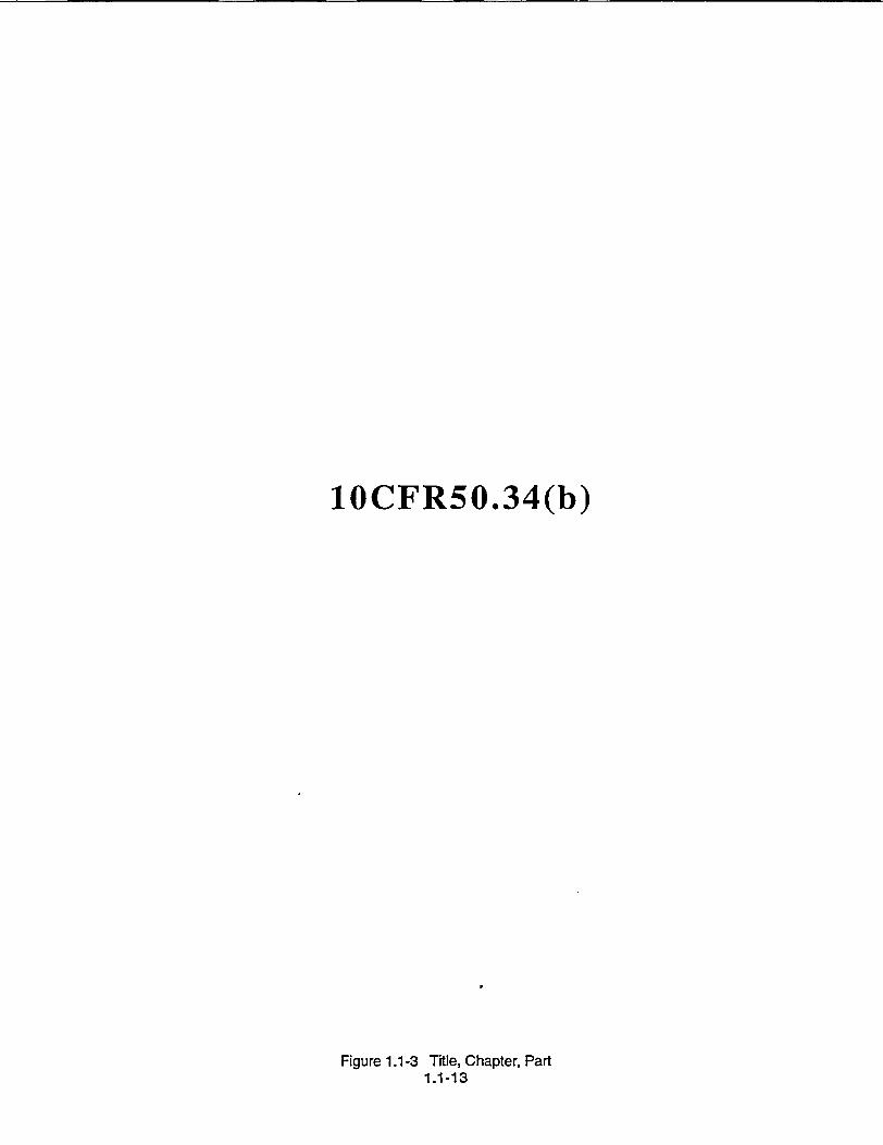
10CFR50.34(b)
Figure 1.1-3 Title, Chapter, Part 1.1-13

TITLE 10 CODE OF FEDERAL REGULATIONS
TABLE OF CONTENTS
Part 2. Policy and procedures related to issuing, amending or revoking an operating license; enforcement actions; and public rule making.
Part 19. Requirements for disseminating information to nuclear plant workers concerning radiological working conditions, enforcement actions, etc. Rules of conduct for NRC inspections.
Part 20. Standards for protection against radiation.
Part 21. Reporting of defects and noncompliances.
Part' 50. Rules for license application, content of applications, facility design requirements, and reporting of events to the NRC.
* Appendix A.
Appendix B.
General Design Criteria for Nuclear Power Plants
Quality Assurance Criteria for Nuclear Power Plants
Figure 1.1-4 Title 10, Table of Contents 1.1-15
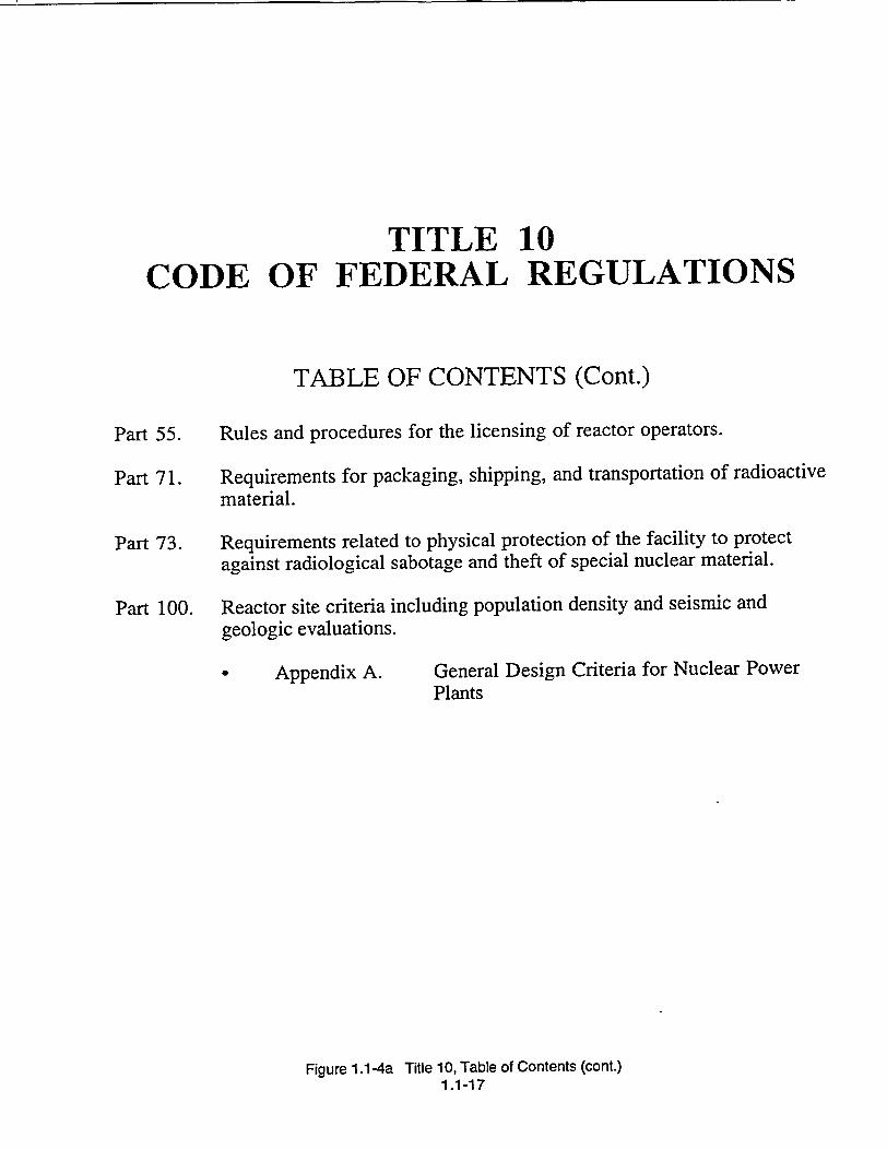
TITLE 10 CODE OF FEDERAL REGULATIONS
TABLE OF CONTENTS (Cont.)
Part 55. Rules and procedures for the licensing of reactor operators.
Part 71. Requirements for packaging, shipping, and transportation of radioactive material.
Part 73. Requirements related to physical protection of the facility to protect against radiological sabotage and theft of special nuclear material.
Part 100. Reactor site criteria including population density and seismic and geologic evaluations.
Appendix A. General Design Criteria for Nuclear Power Plants
Figure 1.1-4a Title 10, Table of Contents (cont.) 1.1-17
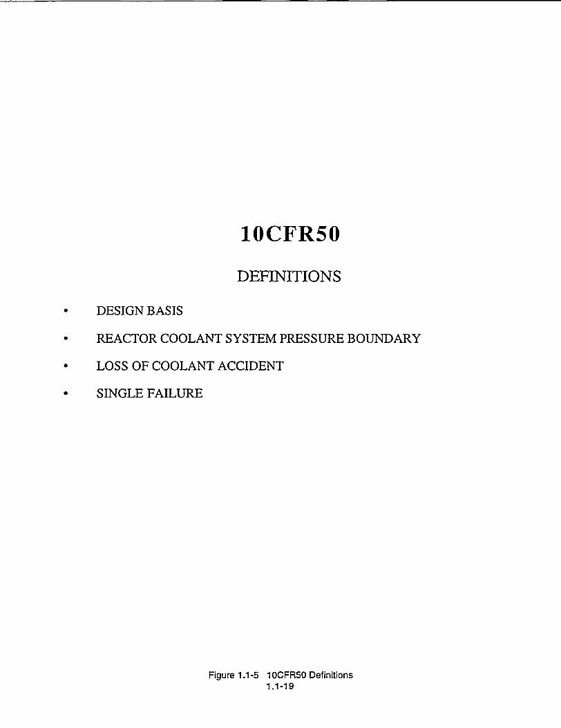
1OCFR50
DEFINITIONS
DESIGN BASIS
REACTOR COOLANT SYSTEM PRESSURE BOUNDARY
LOSS OF COOLANT ACCIDENT
SINGLE FAILURE
Figure 1.1-5 10CFR50 Definitions 1.1-19
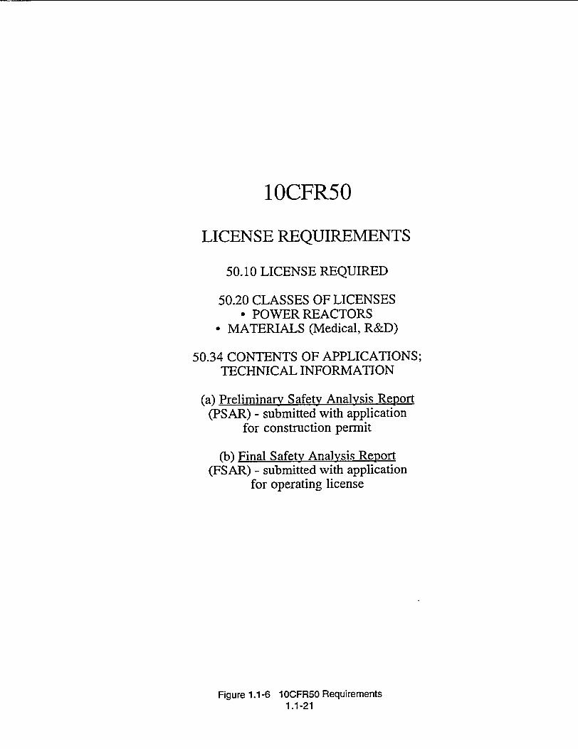
10CFR50
LICENSE REQUIREMENTS
50.10 LICENSE REQUIRED
50.20 CLASSES OF LICENSES - POWER REACTORS
• MATERIALS (Medical, R&D)
50.34 CONTENTS OF APPLICATIONS; TECHNICAL INFORMATION
(a) Preliminary Safety Analysis Report (PSAR) - submitted with application
for construction permit
(b) Final Safety Analysis Report (FSAR) - submitted with application
for operating license
Figure 1.1-6 1OCFR50 Requirements 1.1-21
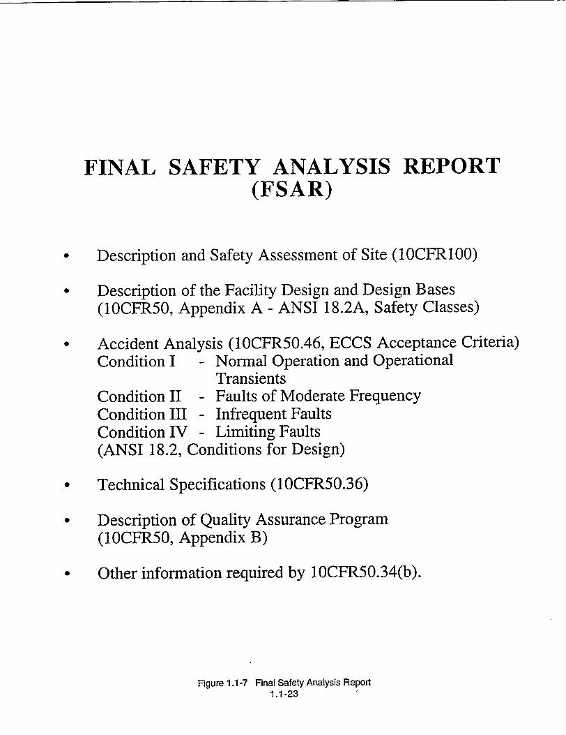
FINAL SAFETY ANALYSIS REPORT (FSAR)
* Description and Safety Assessment of Site (10CFR100)
Description of the Facility Design and Design Bases (10CFR50, Appendix A - ANSI 18.2A, Safety Classes)
Accident Analysis (1OCFR50.46, ECCS Acceptance Criteria) Condition I - Normal Operation and Operational
Transients Condition II - Faults of Moderate Frequency Condition III - Infrequent Faults Condition IV - Limiting Faults (ANSI 18.2, Conditions for Design)
* Technical Specifications (1OCFR50.36)
* Description of Quality Assurance Program (10CFR50, Appendix B)
* Other information required by 10CFR50.34(b).
Figure 1.1-7 Final Safety Analysis Report 1.1-23

10CFR50.36 TECHNICAL SPECIFICATIONS
* Chapter 16 of FSAR
* Validate assumptions made in FSAR
* Issued to facility as Appendix A to the Operating License
1OCFR50.36(c) REQUIRES THE FOLLOWING TO BE INCLUDED IN
THE TECHNICAL SPECIFICATIONS:
* SAFETY LIMITS
0 LIMITING SAFETY SYSTEM SETTINGS
* LIMITING CONDITIONS FOR OPERATION
* SURVEILLANCE REQUIREMENTS
* DESIGN FEATURES
0 ADMINISTRATIVE CONTROLS
Figure 1.1-8 Technical Specifications 1.1-25
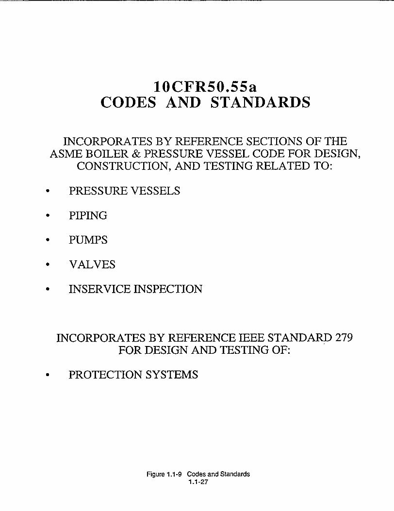
10CFR50.55a CODES AND STANDARDS
INCORPORATES BY REFERENCE SECTIONS OF THE ASME BOILER & PRESSURE VESSEL CODE FOR DESIGN,
CONSTRUCTION, AND TESTING RELATED TO:
* PRESSURE VESSELS
* PIPING
• PUMPS
* VALVES
* INSERVICE INSPECTION
INCORPORATES BY REFERENCE IEEE STANDARD 279 FOR DESIGN AND TESTING OF:
• PROTECTION SYSTEMS
Figure 1.1-9 Codes and Standards 1.1-27

U. S. Nuclear Regulatory Commission Regulatory Guides
• AMPLIFY CODE OF FEDERAL REGULATIONS
* ENDORSE/SUPPLEMENT INDUSTRY STANDARDS
PROVIDE GUIDANCE AND/OR ADDITIONAL INFORMATION
REGULATORY GUIDE PARTS:
A. INTRODUCTION
B. DISCUSSION
C. REGULATORY POSITION
D. IMPLEMENTATION
Figure 1.1-10 Regulatory Guides 1.1-29

10CFR100 REACTOR SITE CRITERIA
APPENDIX A, SEISMIC AND GEOLOGIC SITING CRITERIA
* 1OCFR50, APPENDIX A, GENERAL DESIGN
CRITERION 2
- Design bases for protection against natural phenomena
• SAFE SHUTDOWN EARTHQUAKE
0 OPERATING BASIS EARTHQUAKE
* REGULATORY GUIDE 1.29 - SEISMIC DESIGN CLASSIFICATION
- Seismic Category I
Figure 1.1-11 1OCFRIO 1.1-31

ATTACHMENT A
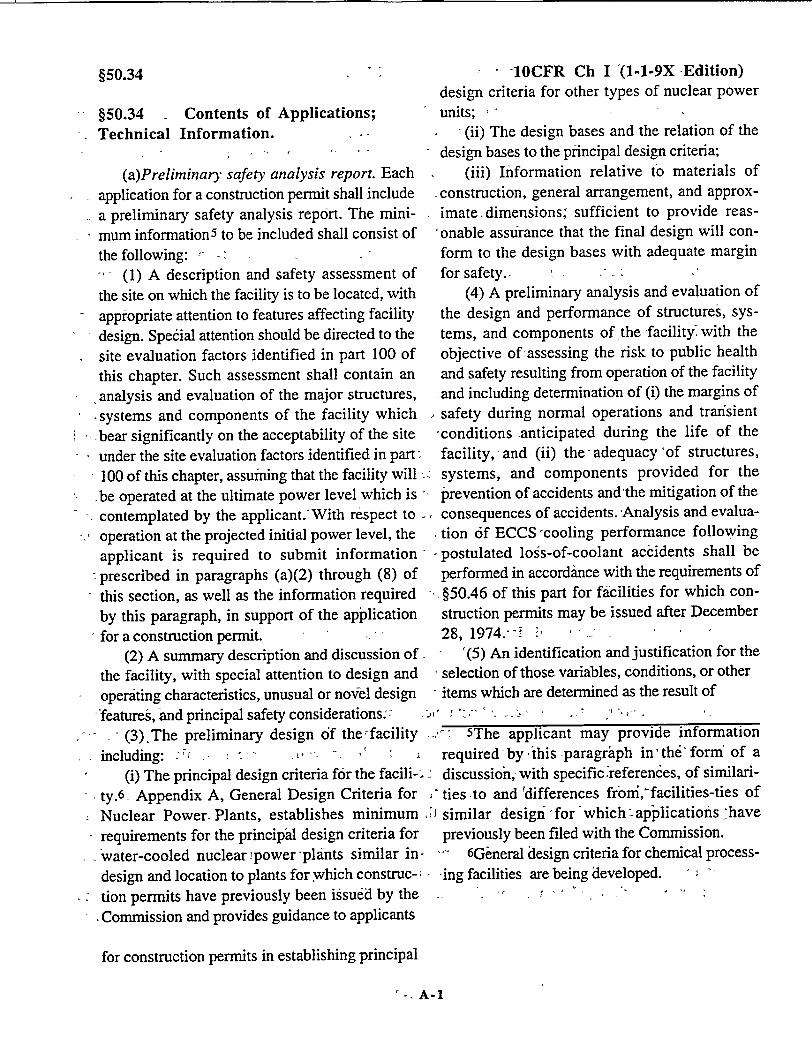
§50.34
§50.34 Contents of Applications; Technical Information.
(a)Preliminary safety analysis report. Each application for a construction permit shall include a preliminary safety analysis report. The minimum information 5 to be included shall consist of the following: " (1) A description and safety assessment of
the site on which the facility is to be located, with appropriate attention to features affecting facility
S design. Special attention should be directed to the
site evaluation factors identified in part 100 of this chapter. Such assessment shall contain an
analysis and evaluation of the major structures, * systems and components' of the facility which -bear significantly on the acceptability of the site under the site evaluation factors identified in partr
100 of this chapter, assuming that the facility will -be operated at the ultimate power level which is
- contemplated by the applicant. With respect to
operation at the projected initial power level, the applicant is required to submit information prescribed in paragraphs (a)(2) through (8) of
this section, as well as the information required by this paragraph, in support of the application
-,for a construction permit. . (2) A summary description and discussion of
the facility, with special attention to design and
operiting characteristics, unusual or noVel design "features, and principal safety considerations.:
(3). The preliminary design of the facility - including: : r - -:,
(i) The principal design criteria for the facili-; ty.6 . Appendix A, General Design Criteria for
. Nuclear Power- Plants, establishes minimum requirements for the principal design criteria for
- water-cooled nuclear power-plants similar in
design and location to plants for which construc
* tion permits have previously been issued by the
SCommission and provides guidance to applicants
for construction permits in establishing principal
I -1OCFR Ch I -(1-1-9X -Edition) design criteria for other types of nuclear power units;
(ii) The design bases and the relation of the
design bases to the principal design criteria; (iii) Information relative to materials of
construction, general arrangement, and approximate.dimensions; sufficient to provide reas
"onable assurance that the final design will conform to the design bases with adequate margin for safety. -
(4) A preliminary analysis and evaluation of
the design and performance of structures, systems, and components of the facility with the
objective of assessing the risk to public health and safety resulting from operation of the facility and including determination of (i) the margins of safety during normal operations and transient "conditions -anticipated during the life of the
facility,' and (ii) the-adequacy of structures, systems, and components provided for the "prevention of accidents and 'the mitigation of the consequences of accidents. Analysis and evalua
tion 6f ECCS -cooling performance following postulated logs-of-coolant accidents shall be
performed in accordance with the requirements of
, §50.46 of this part for facilities for which construction permits may be issued after December 28, 1974.-- i:
'(5) An identification and justification for the - selection of those variables, conditions, or other
"items which are determined as the result of
5The applicant may provide information
required -by 'this paragraph in' the" form of a
discussion, with specific referen6es, of similari,'ties -to and "differences froni,"facilities-ties of
similar design" for which applications -have previously been filed with the Commission.
"I- 6General design criteria for chemical process
-ing facilities are being developed. '
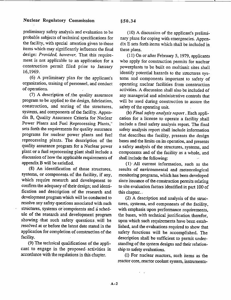
Nuclear Regulatory Commission
preliminary safety analysis and evaluation to be probable subjects of technical specifications for the facility, with special attention given to those items which may significantly influence the final design: Provided, however, That this requirement is not applicable to an application for a construction permit filed prior to January 16,1969.
(6) A preliminary plan for the applicant's organization, training of personnel, and conduct of operations.
(7) A description of the quality assurance program to be applied to the design, fabrication, construction, and testing of the structures, systems, and components of the facility. Appendix-B, Quality Assurance Criteria for Nuclear Power Plants and Fuel Reprocessing Plants," sets forth the requirements, for quality assurance programs for nuclear power plants and fuel reprocessing plants. The description of the quality assurance program for a Nuclear power plant or a fuel reprocessing plant shall include a discussion of how the applicable requirements of appendix B will be satisfied.
(8) An identification of those structures, systems, or components, of the, facility, if any, which require research and development to confirm the adequacy of their design; and identification and description of the -research and development program which will be conducted to resolve any safety questions associated with such structures, systems or compdnents and i schedule of the research and development program showing, that such safety questions& will be resolved at or before the latest date stated in the application for completion of construction of the facility.
(9) The technical qualifications of the applicant to engage in the proposed, activities in accordance with the regulations in this chapter.
(10) A discussion of the applicant's preliminary plans for coping with emergenciesý. Appendix E sets forth items which shall be included in these plans.
(11) On or after February 5, 1979, applicants who apply for construction permits for nuclear powerplants to be built on multiunit sites shall identify potential hazards to the structures systems and components important to safety of operating nuclear facilities from construction activities. A discussion shall also be included of any managerial and administrative controls that will be used during construction to assure the safety of the operating unit.
(b) Final safety analysis report. Each application for a license to operate a facility, shall include a final safety analysis report. The final safety analysis report shall include information that describes the facility, presents the design bases and the limits on its operation, and presents a safety analysis of the structures, systems, and components and of the facility as a whole, and shall include the following: .
(1), All current information, such as the results of environmental and meteorological monitoring programs, which has been developed since issuance of the construction permits relating to site evaluation factors identified in part 100 of this chapter..
(2) A description and analysis of the structures, systems, and components of the facility, with emphasis upon performance requirements, the bases, with technical justification. therefor, upon which such requirements have been established, and the evaluations required to show that safety functions will be accomplished. The description shall be sufficient to permit understanding of the system designs and their relationship to safety evaluations.
(i) For nuclear reactors, such items as the reactor core, reactor coolant system, instrumenta-
A-2
-1
§50.34
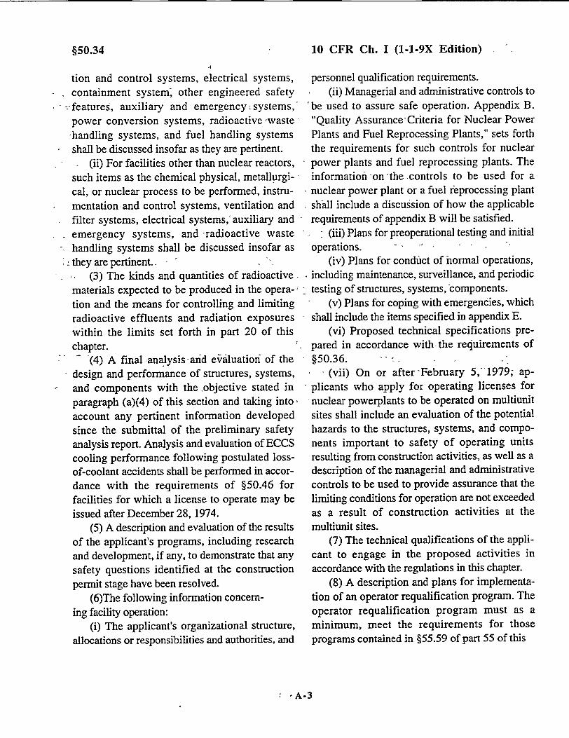
10 CFR Ch. I (1-1-9X Edition)
tion and control systems, electrical systems, containment system, other engineered safety
" :-features, auxiliary and emergency . systems,' power conversion systems, radioactive waste -handling systems, and fuel handling systems shall be discussed insofar as they are pertinent.
(ii) For facilities other than nuclear reactors, such items as the chemical physical, metallurgical, or nuclear process to be performed, instrumentation and control systems, ventilation and filter systems, electrical systems,' auxiliary and Semergency systems, and -radioactive waste
-. handling systems shall be discussed insofar as they are pertinent..
(3) The kinds and quantities of radioactivematerials expected to be produced in the opera-' tion and the means for controlling and limiting radioactive effluents and radiation exposures within the limits set forth in part 20 of this chapter.
.(4) A final analysis aand e,•iluation- of the design and performance of structures, systems, and components with the objective stated in paragraph (a)(4) of this section and taking into, account any pertinent information developed since the submittal of the preliminary safety analysis report. Analysis and evaluation of ECCS cooling performance following postulated lossof-coolant accidents shall be performed in accordance with the requirements of §50.46 for facilities for which a license to operate may be issued after December 28, 1974.
(5) A description and evaluation of the results of the applicant's programs, including research and development, if any, to demonstrate that any safety questions identified at the construction permit stage have been resolved.
(6)The following information concerning facility operation:
(i) The applicant's organizational structure, allocations or responsibilities and authorities, and
personnel qualification requirements. (ii) Managerial and administrative controls to
"be used to assure safe operation. Appendix B. "Quality Assurance Criteria for Nuclear Power Plants and Fuel Reprocessing Plants," sets forth the requirements for such controls for nuclear power plants and fuel reprocessing plants. The information on the -controls to be used for a nuclear power plant or a fuel reprocessing plant shall include a discussion of how the applicable requirements of appendix B will be satisfied.
(iii) Plans for preoperational testing and initial operations.
(iv) Plans for conduct of normal operations, including maintenance, surveillance, and periodic
"testing of structures, systems, components: (v) Plans for coping with emergencies, which
shall include the items specified in appendix E. (vi) Proposed technical specifications pre
pared in accordance with, the requirements of §50.36.
- (vii) On or after-February 5, 1979; ap
plicants who apply for operating licenses for -nuclear powerplants to be operated on multiunit sites shall include an evaluation of the potential hazards to the structures, systems, and components important to safety of operating units resulting from construction activities, as well as a description of the managerial and administrative controls to be used to provide assurance that the limiting conditions for operation are not exceeded as a result of construction activities at the multiunit sites.
(7) The technical qualifications of the applicant to engage in the proposed activities in accordance with the regulations in this chapter.
(8) A description and plans for implementation of an operator requalification program. The operator requalification program must as a minimum, meet the requirements for those programs contained in §55.59 of part 55 of this
- A-3
§50.34

Nuclear Regulatory Commission
chapter. (9) A descriptior of protection provided
against pressurized thermal shock events, including projected values of the reference temperature for reactor vessel beltline materials as defined in §50.61 (b)(1) and (b)(2).
(c) Physical security plan. Each application for a license to operate a production or utilization facility shall include a physical security plan. The plan shall consist of two parts. Part I shall address vital equipment, vital areas, and isolation zones, and shall demonstrate how the applicant plans to comply with the requirements of part 73 (and part 11 of this chapter, if applicable, including the identification and description of jobs as required by § 11.1 (a), at the proposed facility). Part II shall list tests, inspections, and other means to be used to demonstrate compliance with such requirements, if applicable.
(d) Safeguards contingency plan. Each application for a license to operate a production or utilization facility that will be subject to §§73.50, 73.55, or §73.60 of this. chapter must include a licensee safeguards contingency plan in
accordance with the criteria set forth in appendix C to 10 CFR part 73. The safeguards contingency plan shall include plans for dealing with threats, thefts, and radiological sabotage, as defined in part 73 of this chapter, relating to the special nuclear material and nuclear facilities licensed under this chapter and in the applicant's possession and control. Each application for such a license shall include the first four categories of information contained in the applicant's safeguards, contingency plan. (The first four categories of information as set forth in appendix C to 10 CFR part 73 are Background, Generic Planning, Base, and Responsibility Matrix. The fifth category of information, Procedures, does not have to be submitted for approval.) 7
7A physical secunty plan that contains all the information required in both §73.55 and appendix C to part 73 satisfies the requirement for a contingency plan.
A-4
§50.34

10 CFR Ch.iI (1-1-9X Edition) -
§50.36 Technical specifications.
(a) Each applicant for a license authorizin operation of a production or utilization facilit' shall include in his application proposed technicz specifications in accordance with the require ments of this section. A summary statement o the bases -orreasons for such specifications
-other than those covering administrative controls ,shall also be included in the application, but shal
not become part of the technical specifications. (b) Each license authorizing operation of
production or utilization.facility of a type de scribed in §50.21 or §50.22 will include techni cal specifications. The technical specification will be derived fromthe analyses and evaluatioi included in the safety analysis report, and amend ments thereto, submitted pursuant to §50.34.*Th, ...Commission may include such additional techni cal specifications as the Commission find
-appropriate. .,(c) Technical specifications will include
.items in the following categories: . (1) Safety. limits, limiting safety syster,
- settings, and limiting control settings. (i)(A Safety limits for nuclear reactors are limits upoi -important process variables that are found to bi
Snecessary to reasonably protect the integrity o . certain of the physical barriers that guard agains
the uncontrolled release of radioactivity. If an, safety limit is exceeded, the reactor must be shu down. The licensee shall notify the Commissio: review the matter, and record the results of th review, including the cause of the condition an( the basis for corrective action taken to preclud recurrence. Operation must not be resumed unti authorized by the Commission. The licensee sha] retain the record of the results of each revieN until the Commission terminates the license fo the reactor, except for nuclear power reactors licensed under §50.21(b) or §50.22 of this part.
For these reactors,- the licensee shall ,notify the Commission as required by §50.72 and submit a
go :LicenseeEvent Report to the Commission as y required by §50.73. Licensees in these cases dl shall retain the records of the review for a period - of three years following issuance of a Licensee f. Event Report._
-(B) Safety limits for fuel reprocessing plants are, those bounds within which the process
I1- variables must be maintained for adequate control ,-.of the operation and that must not be exceeded in a- order to protect the integrity of the physical - system that is designed *to guard against the - uncontrolled release or radioactivity. If any safety s *limit for a fuel reprocessing plant is exceeded, ri corrective action must be taken as stated in the - technical specification or the affected part of the e process, or the entire process if required, must be - shut down, unless this action would further s reduce,the margin of safety. The licensee shall
-notify the Commission, review the matter, and record the results of the review, including the
- cause of the condition and the basis for corrective I action taken to preclude recurrence. If a portion
) of the:process or the entire process has been 1 shutdown, operation must not be resumed until e authorized by the Commission. The licensee shall f-. retain the record of-the results of each review
;t until-the Commission terminates the license for y,:the plant.- * ••
it -, ,(ii)(A) Limiting safety system settings for n . nuclear reactors are settings for automatic protece -otive devices-related to those variables having I , significant safety functions. Where a limiting e safety, system setting is-specified for a variable on I which a safety limit has been placed, the setting 11[ must be so chosen that automatic protective v -action will correct the abnormal situation before a T, safety limit is exceeded. If, during operation, it is
determined that the automatic safety system does not function as required, the licensee shall take
§50.36
-.•A-5
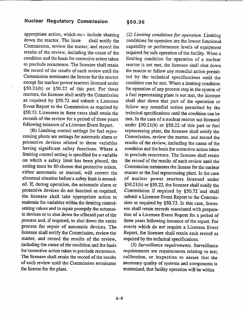
Nuclear Regulatory Commission
approp Iriate action, which mov include shutting down the reactor. The liceno shall notify the Commission, review the matter, and record the results of the review, including the cause of the condition and the basis for corrective action taken to preclude recurrence. The licensee shall retain the record of the results of each review until the Commission terminates the license for the reactor except for nuclear power reactors licensed under §50.21(b) or §50.22 of this part. For these reactors, the licensee shall notify the Conumission as required by §50.72 'and submit a Licensee Event Report to the Commission as required by §50.73. Licensees in these cases shall retain the records of the review for a period of three years following issuance of a Licensee Event Report.
(B) Limiting control settings for fuel reprocessing plants are settings for automatic alarm or protective devices related' to those variables having significant safety functions. Where a limiting control setting is specified for a variable on which a safety limit has been placed, the setting must be 80 chosen that protective action, either automatic or manual, will correct the abnormal situation before a safety limit is exceeded. If, during operation, the automatic alarm or protectie devices do not function as required, the licensee shall take -appropriate action to maintain the variables within the limiting controlsetting values and to repair promptly the automatic devices or to shut down the affected part of the process and, if required, to shut down the entire process for repair of automatic devices. The licensee shall notify the Commission, review the matter, and record the results of the review, including the cause of the` condition and the basis
* for'corrective action taken to preclude recurrence., The licensee shall retain the record of the results of each review until the Commission terminates the license for the plant.
§50.36
(2) Limiting conditions for operation. Limiting conditions for operation are the lowest functional capability or performance levels of equipment required for safe operation of the facility. When a limiting condition for operation of a nuclear reactor is not met, the licensee shall- shut down the reactor or follow any remedial action permitted by the technical specifications until the condition can be met. When a limiting condition for operation of any process step in the system of a fuel reprocessing plant is not met, the licensee shall shut down that part of the operation or follow any remedial action permitted by the technical specifications until the condition can be met. In the case of a nuclear reactor not licensed under §50.21(b) or §50.22 of this part or fuel reprocessing plant, the licensee shall notify the Commission, review the matter, and record the results of the review, including the cause of the condition and the basis for corrective action taken to preclude recurrence. The licensee shall retain the record of the results of each review until the Commission terminates the license for the nuclear reactor or the fuel reprocessing plant. In the case of nuclear power reactors licensed under §50.21(b) or §50.22, the licensee shall notify the Commission if required by §50.72 and shall submit a Licensee Event Report to the Commission as required by §50.73. In this case, licensees shall retain records associated with preparation of a Licensee Event Report for a period of three years following issuance of the report. For events which do not require a Licensee Event Report, the licensee shall retain each record as required by the technical specifications.'
(3) Surveillance requirements. Surveillance requirements are requirements relating to test, calibration, or inspection to assure that the necessary quality of systems and components is maintained, that facility operation will be within
A-6

§50.36
the safety limits, and that the limiting conditions of operation will be met.
(4) Design features. Design features to be included are those features of the facility such as
Smaterials of construction and geometric arrangements, which, if altered or modified, would have a significant effect on safety and are not covered in categories described in paragraphs (c) (1), (2), and (3) of this section.
(5) Administrative controls. Administrative controls are the provisions relating to organization and management, procedures, record keeping, review and audit, and reporting necessary to assure operation of the facility in a safe manner. Each licensee shall submit any reports to the Commission pursuant to approved -technical specifications as specified in §50.4.
10 CFR Ch. I (1-1-9X Edition)
(6) Initial notification._ Reports made to the Commission by licensees in response to the requirements of this section must be made as follows:
(i) Licensees that-have an installed Emergency Notification System shall make the initial notification to the NRC Operations Center in accordance with §50.72 of this part.
(ii) All other licensees shall make the initial notification by telephone to the Administrator of the appropriate NRC Regional Office listed in appendix D, part 20; of this chapter.
(7) Written Reports. Licensees for nuclear power reactors licensed under §50.21(b) and § 50.22 of this part shall submit written reports to the Commission in accordance with §50.73 of this part for events described in paragraphs (c)(1) and (c)(2) of this section. - 1
* -*s
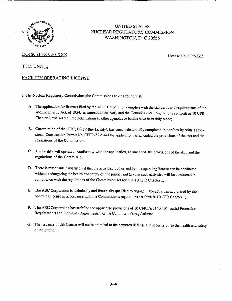
UNITED STATES 47 NUCLEAR REGULATORY COMMISSION
WASHINGTON, D. C 20555
DOCKET NO. 50-XXX License No. DPR-ZZZ
TTC, UNIT 2
FACILITY OPERATING LICENSE
1. The Nuclear Regulatory Commission (the Commission) having found that:
A. The application for licenses filed by the ABC Corporation complies with the standards and requirements of the Atomic Energy Act, of 1954, as amended (the Act), and the Commission's Regulations set forth in 10 CFR Chapter I, and all required notifications to other agencies or bodies have been duly made;
B. Construction of the TTC, Ufnit 2 (the facility), has been substantially completed in conformity with Provisional Construction Permit No. CPPR-ZZZ and the application, as amended the provisions of the Act and the regulations of the Commission;
C. The facility will operate in conformity with the application, as amended, the provisions of the Act, and the regulations of the Commission;
D. There is reasonable assurance: (i) that the activities authorized by this operating license can be conducted without endangering the health and safety of the public, and (ii) that such activities will be conducted in compliance with the regulations of the Commission set forth in 10 CFR Chapter I;
E. The ABC Corporation is technically and financially qualified to engage in the activities authorized by this operating license in accordance with the Commission's regulations set forth in 10 CFR Chapter I;
F. The ABC Corporation has satisfied the applicable provisions of 10 CFR Part 140, "Financial Protection Requirements and Indemnity Agreements", of the Commission's regulations;
G. The issuance of this license will not be inimical to the common defense and security or to the health and safety of the public;
A-8
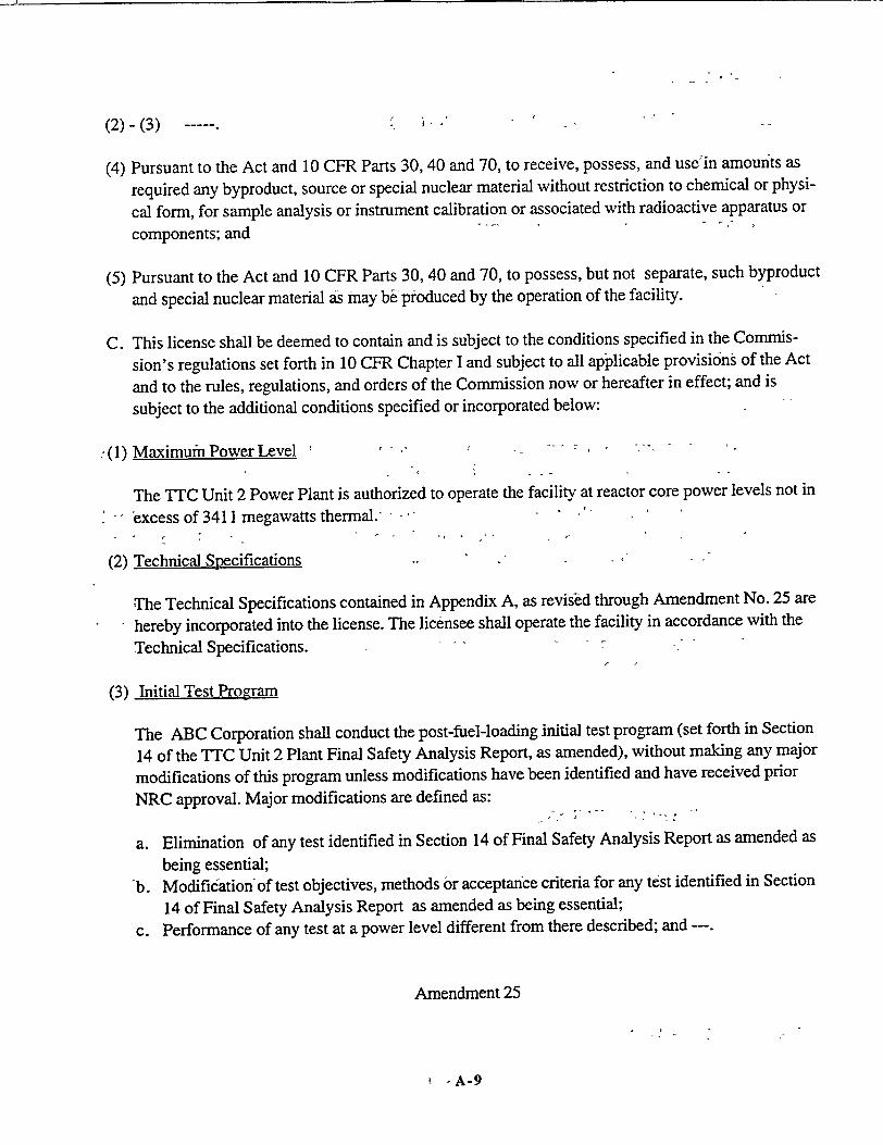
(2)-(3) -
(4) Pursuant to the Act and 10 CFR Parts 30, 40 and 70, to receive, possess, and usein amounts as
required any byproduct, source or special nuclear material without restriction to chemical or physi
cal form, for sample analysis or instrument calibration or associated with radioactive apparatus or
components; and
(5) Pursuant to the Act and 10 CFR Parts 30, 40 and 70, to possess, but not separate, such byproduct
and special nuclear material as may b& produced by the operation of the facility.
C. This license shall be deemed to contain and is subject to the conditions specified in the Commis
sion's regulations set forth in 10 CFR Chapter I and subject to all applicable provisions of the Act
and to the rules, regulations, and orders of the Commission now or hereafter in effect; and is
subject to the additional conditions specified or incorporated below:
(1) Maximumn Power Level
The TTC Unit 2 Power Plant is authorized to operate the facility at reactor core power levels not in
'excess of 3411 megawatts thermal.
(2) Technical Specifications
The Technical Specifications contained in Appendix A, as revis-ed through Amendment No. 25 are hereby incorporated into the license. The licensee shall operate the facility in accordance with the
Technical Specifications.
(3) Initial Test Program
The ABC Corporation shall conduct the post-fuel-loading initial test program (set forth in Section
14 of the TTC Unit 2 Plant Final Safety Analysis Report, as amended), without making any major
modifications of this program unless modifications have been identified and have received prior
NRC approval. Major modifications are defined as:
a. Elimination of any test identified in Section 14 of Final Safety Analysis Report as amended as
being essential; b. Modification of test objectives, methods or acceptance criteria for any test identified in Section
14 of Final Safety Analysis Report as amended as being essential;
c. Performance of any test at a power level different from there described; and
Amendment 25
-A-9

REACTOR COOLANT SYSTEM
3/4.4 3 SAFETY AND RELIEF VALVES - OPERATING
SAFETY VALVES
LIMITING CONDITION FOR OPERATION
3.4.3.1 All pressurizer code safety valves shall be OPERABLE with a lift setting of 2485 psig (_ 2%).
APPLICABILITY: MODES 1, 2, and 3.
ACTION:
a. With a pressurizer code safety valve inoperable, either restore the inoperable valve to OPERABLE status within 15 minutes or be in HOT SHUTDOWN within 12 hours.
b. In the event a safety valve fails or is found inoperable, a Special Report shall be prepared and submitted to the Commission pursuant to Specification 6.9.2 within 30 days. The report shall describe the circumstances surrounding the failure, including the cause, if known.
c. The provisions of Specification 3.0.4 may be suspended for one valve at a time for up to 18 hours for entry into and during operation in MODE 3 for the purpose of setting the pressurizer code safety valves under ambient (hot) conditions provided a preliminary cold setting was made prior to heatup.
SURVEILLANCE REQUIREMENTS
4.4.3 L No additional Surveillance Requirements other than those required by Specification 4.0.5.
TTC - UNIT 2 3/4 4-8
A-10
I
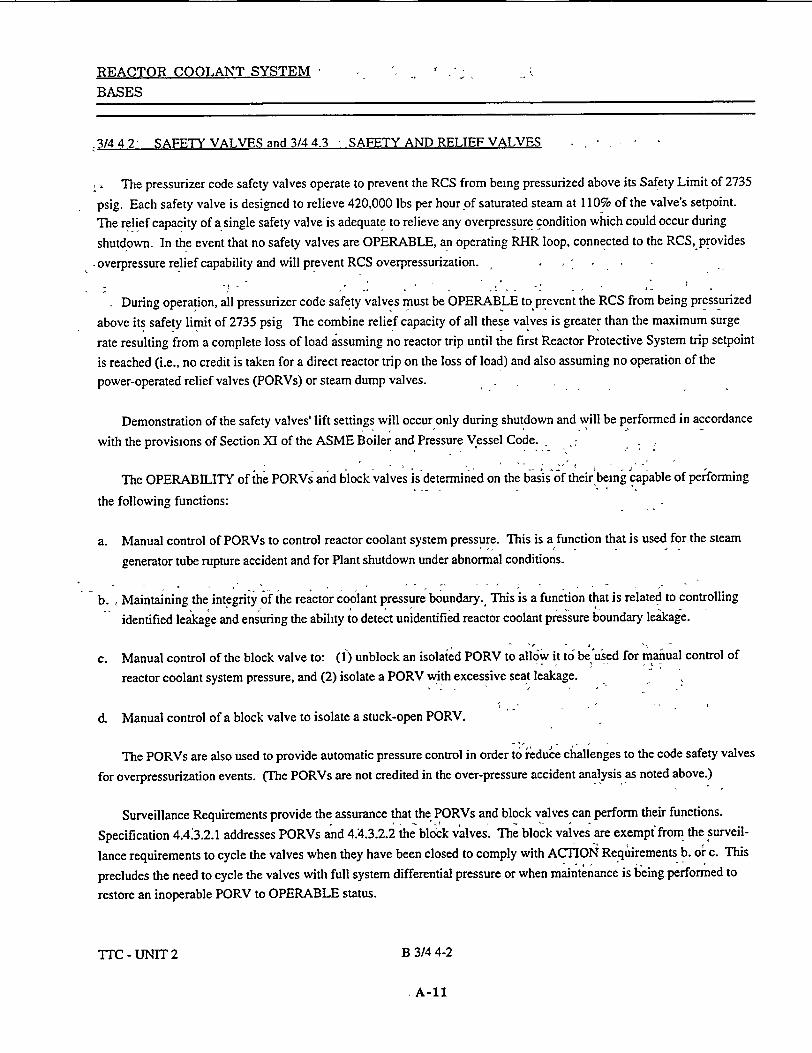
REACTOR COOLANT SYSTEM 7
BASES
.3144 2ý SAFETY VALVES and 3/4 4.3 - SAFETY AND RELIEF VALVES
The pressurizer code safety valves operate to prevent the RCS from being pressurized above its Safety Limit of 2735
psig. Each safety valve is designed to relieve 420,000 lbs per hour of saturated steam at 110% of the valve's setpoint.
The relief capacity of a single safety valve is adequate to relieve any overpressure condition which could occur during
shutdown. In the event that no safety valves are OPERABLE, an operating RHR loop, connected to the RCS, provides
-overpressure relief capability and will prevent RCS overpressurization.
During operation, all pressurizer code safety valves must be OPERABLE to prevent the RCS from being pressurized
above its safety limit of 2735 psig The combine relief capacity of all these valves is greater than the maximum surge
rate resulting from a complete loss of load assuming no reactor trip until the first Reactor Protective System trip setpoint
is reached (i.e., no credit is taken for a direct reactor trip on the loss of load) and also assuming no operation of the
power-operated relief valves (PORVs) or steam dump valves.
Demonstration of the safety valves' lift settings will occur only during shutdown and will be performed in accordance
with the provisions of Section XI of the ASME Boiler and Pressure Vessel Code.
The OPERABILITY of the PORVs and block valves is determined on the basis of their being capable of performing
the following functions:
a. Manual control of PORVs to control reactor coolant system pressure. This is a function that is used for the steam
generator tube rupture accident and for Plant shutdown under abnormal conditions.
b. , Maintaining the integrity of the reactor coolant pressure boundary. This is a function that is related to controlling
identified leakage and ensuring the ability to detect unidentified reactor coolant pressure boundary leakage.
c. Manual control of the block valve to: (1) unblock an isolated PORV to allow it to be used for mafiual control of
reactor coolant system pressure, and (2) isolate a PORV with excessive seat leakage.
d. Manual control of a block valve to isolate a stuck-open PORV.
The PORVs are also used to provide automatic pressure control in order to ieduce challenges to the code safety valves
for overpressurization events. (The PORVs are not credited in the over-pressure accident analysis as noted above.)
Surveillance Requirements provide the assurance that the PORVs and block valves can perform their functions.
Specification 4.4.3.2.1 addresses PORVs and 4.4.3.2.2 the block valves. The block valves are exempt from the surveil
lance requirements to cycle the valves when they have been closed to comply with ACTION Requirements b. oi" c. This
precludes the need to cycle the valves with full system differential pressure or when maintenance is being performed to
restore an inoperable PORV to OPERABLE status.
TITC - UNIT 2 B 3/4 4-2
A-11
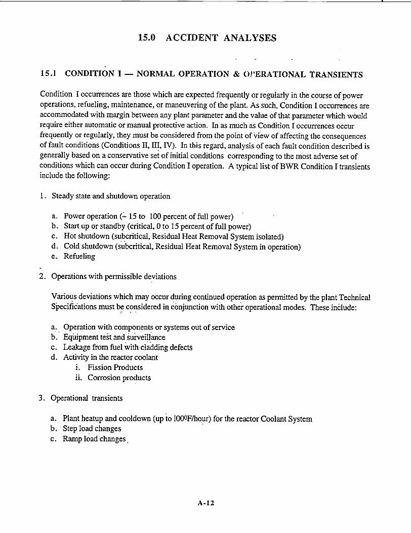
15.0 ACCIDENT ANALYSES
15.1 CONDITION I - NORMAL OPERATION & OPERATIONAL TRANSIENTS
Condition I occurrences are those which are expected frequently or regularly in the course of power operations, refueling, maintenance, or maneuvering of the plant. As such, Condition I occurrences are accommodated with margin between any plant parameter and the value of that parameter which would require either automatic or manual protective action. In as much as Condition I occurrences occur frequently or regularly, they must be considered from the point of View of affecting the consequences of fault conditions (Conditions II, III, IV). In this regard, analysis of each fault condition described is generally based on a conservative set of initial conditions corresponding to the most adverse set of conditions which can occur during Condition I operation. A typical list of BWR Condition I transients include the following:
1. Steady state and shutdown operation
a. Power operation (' 15 to 100 percent of full power) b. Start up or standby (critical, 0 to 15 percent of full power) c. Hot shutdown (subcritical, Residual Heat Removal System isolated) d. Cold shutdown (subcritical, Residual Heat Removal System in operation) e. Refueling
2. Operations with permissible deviations
Various deviations which may occur during continued operation as permitted by the plant Technical Specifications must be considered in conjunction with other operational modes. These include:
a. Operation with components or systems out of service b. Equipment teit and sur-veillance c. Leakage from fuel with cladding defects d. Activity in the reactor coolant
i. Fission Products ii. Corrosion products
3. Operational transients
a. Plant heatup and cooidown (up to 1000F/hour) for the reactor Coolant System b. Step load changes c. Ramp load changes,
A-12
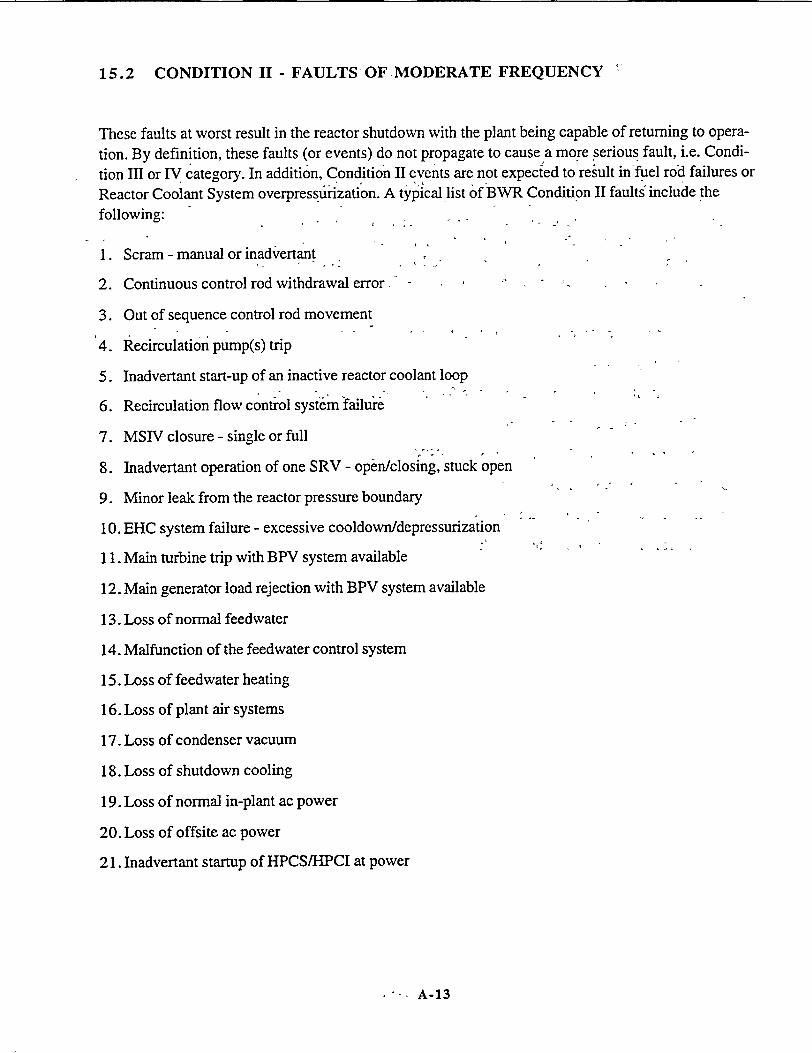
15.2 CONDITION II - FAULTS'OF MODERATE FREQUENCY
These faults at worst result in the reactor shutdown with the plant being capable of returning to opera
tion. By definition, these faults (or events) do not propagate to cause a more serious fault, i.e. Condi
tion Im or IV category. In addition, Condition II events are not expected to result in-fuel rod failures or
Reactor Coolant System overpressurization. A typical list of BWR Condition II faults include the following:..
1. Scram - manual or inadvertant
2. Continuous control rod withdrawal error
3. Out of sequence control rod movement
4. Recirculation pump(s) trip
5. Inadvertant start-up of an inactive reactor coolant loop
6. Recirculation flow control system failurei
7. MSIV closure - single or full
8. Inadvertant operation of one SRV - open/closing, stuck open
9. Minor leak from the reactor pressure boundary
10. EHC system failure - excessive cooldown/depressurization
11. Main turbine trip with BPV system available
12. Main generator load rejection with BPV system available
13. Loss of normal feedwater
14. Malfunction of the feedwater control system
15. Loss of feedwater heating
16. Loss of plant air systems
17. Loss of condenser vacuum
18. Loss of shutdown cooling
19. Loss of normal in-plant ac power
20. Loss of offsite ac power
21. Inadvertant startup of HPCS/HPCI at power
"- A-13
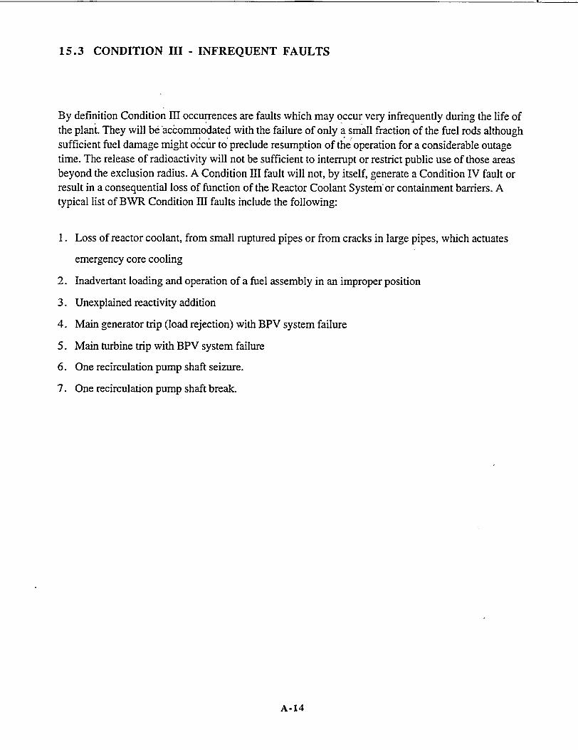
15.3 CONDITION III - INFREQUENT FAULTS
By definition Condition III occurrences are faults which may occur very infrequently during the life of the plant. They will be accommodated with the failure of only a small fraction of the fuel rods although sufficient fuel damage might occur to' preclude resumption of the operation for a considerable outage time. The release of radioactivity will not be sufficient to interrupt or restrict public use of those areas beyond the exclusion radius. A Condition III fault will not, by itself, generate a Condition IV fault or result in a consequential loss of function of the Reactor Coolant System'or containment barriers. A typical list of BWR Condition III faults include the following:
1. Loss of reactor coolant, from small ruptured pipes or from cracks in large pipes, which actuates
emergency core cooling
2. Inadvertant loading and operation of a fuel assembly in an improper position
3. Unexplained reactivity addition
4. Main generator trip (load rejection) with BPV system failure
5. Main turbine trip with BPV system failure
6. One recirculation pump shaft seizure.
7. One recirculation pump shaft break.
A-14

15.4' CONDITION IV - LIMITING FAULTS
Condition IV occurrences are faults which are not expected to take place, but are postulated because their consequences would include the potential or,the release of significant amounts of radioactive
material. These are the most drastic which must be designed against and thus represent limiting design
cases. Condition IV faults are not to cause a fission product release to the environment resulting in an
undue risk to the public health and safety in excess of guideline values of 1OCFR Part 100. A single
Condition IV fault is not to cause a consequential loss of required functions of systems needed to
cope with the fault including those of the Emergency Core Cooling System (ECCS), and the contain
ment. A typical list of BWR Condition IV faults include the following:
L. Major rupture of piping containing reactor coolant up to and including double-ended rupture of the largest pipe in the reactor coolant pressure boundary located inside the primary containment (loss
of coolant accident). 2: Small to large steam and liquid piping breaks outside the priniary containment. 4. Control iod drop accident. 5. Control rod drive housing rupture.' 6. Fuel handling accident.
The analysis of thyroid and whole body doses, resulting from Safety Analysis Report. The fission:
product inventories which form a basis for these calculations are presented in Chapter 11 and Section
15.1. The Safety Analysis Report also includes the discussion of systems interdependency contribut
ing to limiting fission product leakages from the containment following a Condition IV occurrence.
..: A-15

U.S. NUCLEAR REGULATORY COMMISSION Revision 3 September 1978
.REGULATORY GUIDE OFFICE OF STANDARDS DEVELOPMENT
REGULATORY GUIDE 1.29 SEISMIC DESIGN CLASSIFICATION
A. INTRODUCTION
General Design Criterion 2, "Design Basis for Protection Against Natural Phenomena," of Appendix A, "General Design Criteria for Nuclear Power Plants," to 10 CFR Part 50, "Domestic Licensing of Production and Utilization Facilities," requires that nuclear power plant structures, systems, and components important to safety be designed to withstand the effects of earthquakes without loss of capability to perform their safety functions.
Appendix B, "Quality Assurance Criteria for Nuclear Power Plants and Fuel Reprocessing Plants," to 10 CFR Part 50 establishes quality assurance requirements for the design, construction, and operation of nuclear power plant structures, systems, and components that prevent or mitigate the consequences of postulated accidents that could cause undue risk to the health and safety of the public. The pertinent requirements of Appendix B apply to all activities affecting the safetyrelated functions of those structures, systems, and components.
Appendix A, "Seismic and Geologic Siting Criteria for Nuclear Power Plants," to 10 CFR Part 100, 'Reactor Site Criteria," requires that all nuclear power plants be designed so that, if the Safe Shutdown Earthquake (SSE) occurs, certain structures, systems, and components remain functional. These plant features are those necessary to ensure (1) the integrity of the reactor coolant pressure boundary, (2) the capability to shut down the reactor and maintain it in a safe shutdown condition, or (3) the capability to prevent or mitigate the consequences of accidents that could result in potential offsite exposures comparable to the guideline exposures of 10 CFR Part 100.
USNRC REGULATORY GUIDES Regulatory Guides are issued to describe and make available to thk pu ic me hods acceptable to the NRC staff .f implementing specifi c parts of the Commission's regulations, to delineate techniques used by the staff in evaluating specific problems or stulated accidents, or provide guidance to app icants. Regulatory Guides are not substitutes for regufations and compliance wit them is not required Methods and solutions different from those let out in the guides will be acceptable i t hey provide a basis •or the findings requisite to the issuance or continuance of a permit or license by the Commission. Comments and suggestions for improvements in these guides are encouraged at all times, and guides will be rmvised, as appropriate, to accommodate comments and to reflect new information or experience. This Vide was revised as a result of substantive comments received from e and additional staff review.
This guide describes a method acceptable to the NRC for identifying and classifying those features of light--water-
cooled nuclear power plants that should be designed to withstand the effects of the SSE. The Advisory staff Committee on Reactor Safeguards has been consulted regarding this guide and has concurred in the regulatory position.
B. DISCUSSION
After reviewing a number of applications for construction permits and operating licenses for boiling and pressurized water nuclear power plants, the NRC staff has developed a seismic design classification system for identifying those ]plant feature that should be designed to withstand the effects of the SSE. Those structures, systems, and components that should be designed to remain functional if the SSE occurs have been designated as Seismic Category I.
C. REGULATORY POSITION
1. The following'structures, systems, and components of a nuclear power plant, including their foundations and supports, are designated as Seismic Category I and should be designed to withstand the effects of the SSE and remain functional. The pertinent quality assurance requirements of Appendix B to 10 CFR Part 50 should be applied to all activities affecting the safety-related functions of these structures, systems, and components.
a. The reactor coolant pressure boundary.
b. The reactor core and reactor vessel internals.
Comments should be sent to the Secretary of the Commission. U.S. Nuclear Regulatory Commission, Washington, D C. 20555, Attention: Docketing and Service Branch.
The guides are issued in the following ten broad divisions:
I. Power Reactors 7 Transportation " Research and Test Reaqtors 8. Occupational Health 3 Fuels and Materials Facilities 9. Antitrust and Financial 4 EnvirQnmental and Siting Review 5 Materials and Plant Protection 10. General 6 Products
Requests for single copies of issued guides (which may be reproduced) ?r or placement on at) automatic distribution list for single copies of tuture guides kin specific divisions should be made in writing to the U S. Nuclear Regulatory Commission. Washington, D.C. 20555, Attention: Direcror, Division of Technical lnformaiion and Document Control.
c. Systems) or portions of systems that are required for (1) emergency core cooling, (2) postaccident containment heat removal, or (3) postaccident containment atmosphere cleanup (e.g., hydrogen removal system).
A-16
Q•
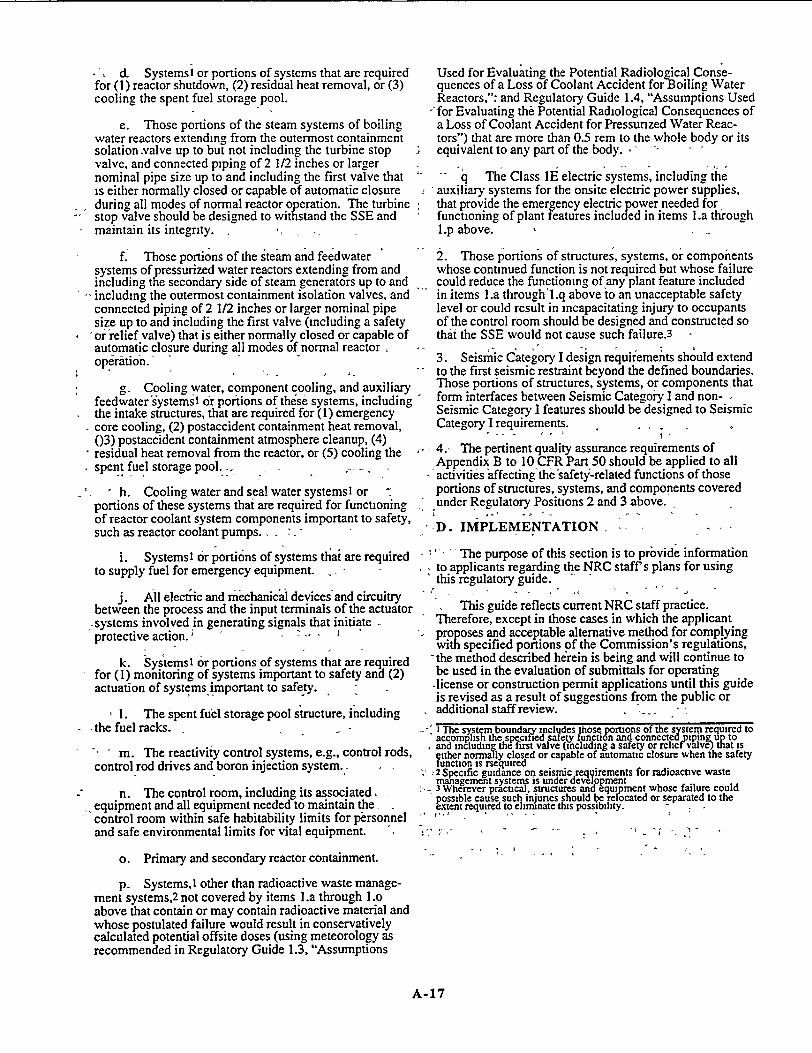
d. Systemsi or portions of systems that are required for (1) reactor shutdown, (2) residual heat removal, or (3) cooling the spent fuel storage pool.
e. Those portions of the steam systems of boiling water reactors extending from the outermost containment solation -valve up to but not including the turbine stop valve, and connected piping of 2 1/2 inches or larger nominal pipe size up to and including the first valve that is either normally closed or capable of automatic closure during all modes of normal reactor operation. The turbine stop valve should be designed to withstand the SSE and maintain its integrity. -
f. Those portions of the steam and feedwater systems of pressurized water reactors extending from and including the secondary side of steam generators up to and including the outermost containment isolation valves,,and connected piping of 2 1/2 inches or larger nominal pipe size up to and including the first valve (including a safety
'or relief valve) that is either normally closed or capable of automatic closure during all modes of normal reactor operation.
g. -Cooling water, component cooling, and auxiliary feedwater systemsl or portions of these systems, including the intake structures, that are required for (1) emergency
- core cooling, (2) postaccident containment heat removal, (03) postaccident containment atmosphere cleanup, (4) residual heat removal from the reactor, or (5) cooling the spent fuel storage pool.
h. Cooling water and seal water systemsl or " portions of these systems thai are required for functioning of reactor coolant system components important to safety, such as reactor coolant pumps. . .
Used for Evaluating the Potential Radiological Consequences of a Loss of Coolant Accident for Boiling Water Reactors,": and Regulatory Guide 1.4, "Assumptions Used
--for Evaluating the Potential Radiological Consequences of a Loss of Coolant Accident for Pressurized Water Reactors") that are more than 0.5 rem to the whole body or its equivalent to any part of the body.
- q The Class IE electric systems, including the auxiliary systems for the onsite electric power supplies, that provide the emergency electric power needed for functoning of plant features included in items l.a thiough L.p above.
2. Those portions of structures, systems, or components whose continued function is not required but whose failure could reduce the functioning of any plant feature included in items l.a through'l.q above to an unacceptable safety level or could result in incapacitating injury to occupants of the control room should be designed and constructed so that the SSE would not cause such failure.3
"3. Seismic Category I design requiiements should extend to the first seismic restraint beyond the defined boundaries. Those portions of structures, systems, or components that form interfaces between Seismic Category I and nonSeismic Category I features should be designed to Seismic Category I requirements.
4.- The pertinent quality assurance requirements of Appendix B to 10 CFR Part 50 should be applied to all
- activities affecting the-safetyi-related functions of those portions of structures, systems, and components covered "under Regulatory Positions 2 and 3 above.
"-D. IMPLEMENTATION - -
i. Systems1 or portions of systems that are required -' - The purpose of this section is to prbvide information to supply fuel for emergency equipment. , to applicants regarding the NRC staff's plans for using
- this regulatory guide. - "
j. All electric and mechanical devices'and circuitry between the process and the input terminals of the actuator
,systems involved in generating signals that initiate protective action. - - .
k. Systems 1 or portions of systems that are required for (1) monitoring of systems important to safety and (2) actuation of systems important to safety.,
I. The spent fuel storage pool structure, including -the fuel racks.
- m. The reactivity control systems, e.g., control rods, control rod drives and boron injection system.
n. The control room, including its associated, ,-equipment and all equipment needed to maintain the
control room within safe habitability limits for personnel and safe environmental limits for vital equipment.
o. Primary and secondary reactor containment.
p. Systems,I other than radioactive waste management systems,2 not covered by items l.a through 1.o above that contain or may contain radioactive material and whose postulated failure would result in conservatively calculated potential offsite doses (using meteorology as recommended in Regulatory Guide 1.3, "Assumptions
This guide reflects current NRC staff practice. Therefore, except in those cases in which the applicant proposes and acceptable alternative method for complying with specified portions of the Commission's regulations,
"-the method described herein is being and will continue to be used in the evaluation of submittals for operating -license or construction permit applications until this guide is revised as a result of suggestions from the public or additional staff review.
i The sy4tm boundary incltdes hose portions of the system required to "accomplis the spesitied satety tunction and connectedgpiprnup to and including the nrst valve (including a safety or relie vave) tat is gither normally closed or capable of automatic closure when the safety function is rsequired 2 Specific guidance or; seismic requirements for radioactive waste management systems is under development 3 Wherever practical, structures and equipment whose failure could possible cause such injunes should be relocated or separated to the extent required to eliminate this possibility. -
A-17

Nuclear Regulatory Commission
DEFINITIONS AND EXPLANATIONS
Nuclear power unit. A nuclear power unit means a nuclear power reactor and associated equipment necessary for electric power generation and includes those structures, systems, and components required to provide reasonable assurance the facility can be operated without undue risk to the health and safety of the public.
Loss of coolant accidents. Loss of coolant accidents mean those postulated accidents that result from the loss of reactor coolant at a rate in excess of the capability of the reactor coolant makeup system from breaks in the reactor coolant plressure boundary up to and including a break equivalent in size to the double-ended rupture of the largest pipe of the reactor coolant system.I
Single failure . A single, failure. means an occurrence which results in the loss of capability of a component to perform its intended safety functions. Multiple failures resulting from a single occurrence are considered to be a sihgle failure. Fluid and electric systems are considered to be designed against an assumed single failure if neither (1) a single failure of any'active component (assuming passive components function properly) nor (2) a single failure of a passive component (assuming active compoonents function properly), results in a loss of the capability of the system to perform its safety, functions. 2
Anticipated operational occurrences. Anticipated-operati6nal occurrences mean those conditions of normal operation which are expected to occur one or more times during the life of the nuclear power unit and include but are not limited to loss of power to all recirculation pumps, tripping of the turbine generator set, isolation of the main condenser, and loss of all offsite power.
CRITERIA
I. Overall Requirements
Criterion l-Quality standards and records. Structures, systems, and components important to safety shall be designed, fabricated, erected, and tested to quality standards commensurate with the importance of the safety functions to be performed. Where generally recognized codes and standards are used, they shall be identified and evaluated to determine their applicability, adequacy, and sufficiency and shall be supplemented or modified as necessary to assure a quality product in keeping with the required safety function. A quality assurance program shall be established and implemented in order to provide adequate assurance that these structures, systems, and components will satisfactorily perform their safety functions. Appropriate records of the design, fabrication, erection, and testing of structures, systems. and components important to safety shall be maintained by or under the control of the nuclear power unit licensee throughout the life of the unit;
'Further details relating to the type, size, aind orientation of postulated breaks in specific components- of the reactor coolant -pressure boundary are under development.
2 Single failures of passive components in electric systems should be assumed in designing against a single failure. The conditions under which a single failure of a passive component in a fluid system should be considered in designing the system against a single failure are under development.
A-18
Part 50, App. A
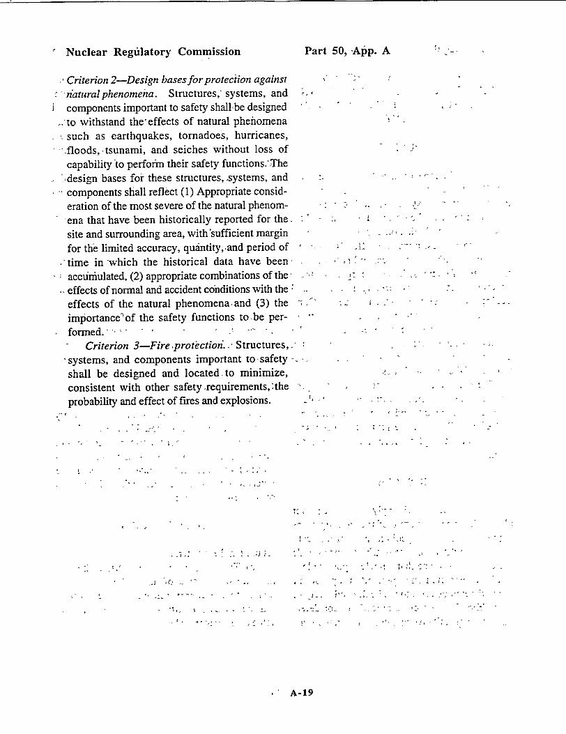
Nuclear Regfilatory Commission P.
Criterion 2-Design bases for proteciion against "--ntaturalphenomena. Structures, systems, and
components important to safety shallbe designed --to withstand the-effects of natural phenomena
such as earthquakes, tornadoes, hurricanes, --floods,, tsunami, and seiches without loss of capability to perform their safety functions.'The
'-design bases for these structures, systems, and components shall reflect (1) Appropriate consideration of the most severe of the natural phenom
-ena that have been historically reported for the, site and surrounding area, with sufficient margin for the limited accuracy, quantity,,and period of
.-time in:which the historical data have been, accuiimulated, (2) appropriate combinations of the, effects of normal and accident conditions with the,* effects of the natural phenomena and (3) the importance-of the safety functions to be perf o r m e d . ' -,' ' - .... .
Criterion 3-Fire 4protectioni., Structures, "systems, and components important to safety -
shall be designed and located-to minimize, consistent with other safety requirements, the probability and effect of fires and explosions.
art 50, ýAtp. A
4�4
- 4.
I, -
C A
- ' 4'
4' - 4
-4 � . .- -
I-.
4 4�.
3.
S .- A
C-,:
A-19
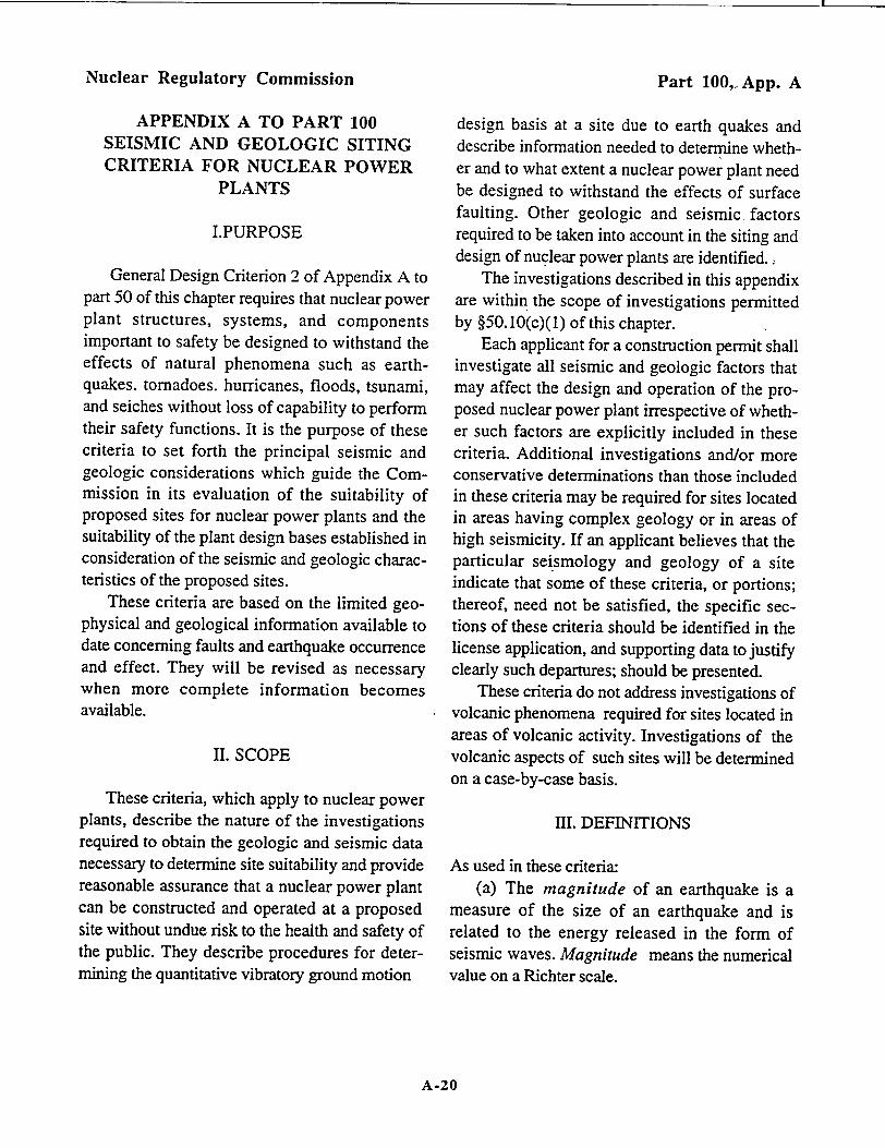
Nuclear Regulatory Commission
APPENDIX A TO PART 100 SEISMIC AND GEOLOGIC SITING CRITERIA FOR NUCLEAR POWER
PLANTS
I.PURPOSE
General Design Criterion 2 of Appendix A to part 50 of this chapter requires that nuclear power plant structures, systems, and components important to safety be designed to withstand the effects of natural phenomena such as earthquakes. tornadoes. hurricanes, floods, tsunami, and seiches without loss of capability to perform their safety functions. It is the purpose of these criteria to set forth the principal seismic and geologic considerations which guide the Commission in its evaluation of the suitability of proposed sites for nuclear power plants and the suitability of the plant design bases established in consideration of the seismic and geologic characteristics of the proposed sites.
These criteria are based on the limited geophysical and geological information available to date concerning faults and earthquake occurrence and effect. They will be revised as necessary when more complete information becomes available.
II. SCOPE
These criteria, which apply to nuclear power plants, describe the nature of the investigations required to obtain the geologic and seismic data necessary to determine site suitability and provide reasonable assurance that a nuclear power plant can be constructed and operated at a proposed site without undue risk to the health and safety of the public. They describe procedures for determining the quantitative vibratory ground motion
Part 100, App. A
design basis at a site due to earth quakes and describe information needed to determine whether and to what extent a nuclear power plant need be designed to withstand the effects of surface faulting. Other geologic and seismic- factors required to be taken into account in the siting and design of nuclear power plants are identified.
The investigations described in this appendix are within the scope of investigations permitted by §50.10(c)(1) of this chapter.
Each applicant for a construction permit shall investigate all seismic and geologic factors that may affect the design and operation of the proposed nuclear power plant irrespective of whether such factors are explicitly included in these criteria. Additional investigations and/or more conservative determinations than those included in these criteria may be required for sites located in areas having complex geology or in areas of high seismicity. If an applicant believes that the particular seismology and geology of a site indicate that some of these criteria, or portions; thereof, need not be satisfied, the specific sections of these criteria should be identified in the license application, and supporting data to justify clearly such departures; should be presented.
These criteria do not address investigations of volcanic phenomena required for sites located in areas of volcanic activity. Investigations of the volcanic aspects of such sites will be determined on a case-by-case basis.
III. DEFINITIONS
As used in these criteria: (a) The magnitude of an earthquake is a
measure of the size of an earthquake and is related to the energy released in the form of seismic waves. Magnitude means the numerical value on a Richter scale.
A-20
- I
Nuclear Regulatory Commission
(b) The intensity of an earthquake is a measure of its effects on man, on man-built structures, and on the earth's surface at a particular location. Intensity means the numerical value on the Modified Mercalli scale.
(c) The Safe shutdown Earthquake I is that earthquake which based upon an evaluation of the maximum earthquake potential considering the regional and local geology and seismology
and specific characteristics of local subsurface material. It is that earthquake which produces the maximum" vibratory ground motion for which certain structures, systems, and components are designed to remain functional.
SIThe Safe Shutdown Earthquake defines that earthquake which has commonly been referred to as the Design Basis Earthquake.
A-21
Part 100, App. A

3.2 CLASSIFICATION OF STRUCTURES, SYSTEMS, AND COMPONENTS
3.2.1 Seismic Qualifications
The TTC Unit 2 Nuclear Plant structures, systems, and components important to safety have been designed to remain functional in the event of a Safe Shutdown Earthquake (SSE). These structures, systems, and components, designated as Category I, are those necessary to assure:
1. The integrity of the reactor coolant pressure boundary.
2. The capability to shut down the reactor and maintain it in a safe shutdown condition.
3. The capability to prevent or mitigate the consequences of accidents which could result in potential offsite exposures comparable to the guideline exposures of 10 CFR Part 100.
Moreover, those safety-related structures, systems, and components necessary to assure the above requirements, have been designed to stress limits that are well within the material yield limits to withstand the loading effects of vibratory motion of at least 50 percent of the SSE.
Those components which are important to reactor operation but not essential to the safe shutdown and isolation of the reactor and whose failure could not result in a release of substantial amounts of radioactivity, but are in close proximity to Category I components, have been seismically qualified to retain limited structural integrity during a SSE, if they have to mitigate the affects of a design basis accident such as a LOCA or steam/feedwater line break.
Category II classification for structures, systems and components is not applicable since the TTC Unit 1 Nuclear Plant was not designed
for an Operating Basis Earthquake(OBE) as defined in the Guide for Safety Analysis Report Preparation, Revision 1, October 1972. There are no structures which are partially Category I and partially in a lesser category. Where portions of mechanical systems are'Category I and then remaining portions are not seismically classified, the systems have been seismically qualified through the first seismic restraint beyond the defined boundary such as a valve.
All Category I safety-related structures, portions of mechanical systems, and electrical systems and components are listed in, Tables 3.2.1-1, 3.2.1-2, and 3.2.1-3, respectively. Category I mechanical fluid components are indicated by the applicable "Seismic Qualification Methods in the coluimn so designated (Table 3.2.1-2). These structures, systems, and components are classified in accordance with Regulatory Guide 1.29 and are designed to remain functional as required to safely shutdown and maintain the reactor in a safe condition after a SSE event.
A-22

INSTRUMENTATION
SEISMIC INSTRUMENTATION
LIMITING CONDITION FOR OPERATION
3.3.3.3 The seismic monitoring instrumentation shown in Table 3.3-7 shall be OPERABLE.
APPLICABILITY: At all times.
ACTION:
a. With one or more of the above required seismic monitoring instruments inoperable for
more than 30 days, prepare and submit a Special Report to the Commission pursuant to
Specification 6.9.2 within the next 10 days outlining the cause of the malfunction and the
plans for restoring the instrument(s) to OPERABLE status.
b. The provisions of Specifications 3.0.3 and 3.0.4 are not applicable.
SURVEILLANCE REQUIREMENTS
4 3.3.3. Each of the above required seismic monitoring instruments shall be demonstrated OPERA
BLE by the performance of the CHANNEL CHECK, CHANNEL CALIBRATION and
ANALOG CHANNEL OPERATIONAL TEST at the frequencies shown in Table 4.3-4.
'4.3.3.3.2
TITC
Each of the above required seismic monitoring instruments actuated during a seismic event
greater than'or equal to 0.01g shall be restored to OPERABLE status within 24 hours and
a CHANNEL CALIBRATION performed within 10 days following the seismic event. Data
shall be retrieved from actuated instruments and analyzed to determine the magnitude of the
vibratory ground motion A Special Report shall be prepared and submitted to the Commis
sion pursuant to Specification 6.9'2 withiri 14 ddys describing the- magnitude, frequency
spectrum and resultant effect upon facility features important to safety.
3/4 3-43
A-23
INSTRUMENTATION BASES
3/4.3.3.3 SEISMIC INSTRUMENTATION
The Operability of the seismic instrumentation ensures that sufficient capability is available to promptly determine the magnitude of a seismic event and evaluate the response of those features important to safety This capability is required to permit comparison of the measured response to that used in the design basis for the facility to determine if plant shutdown is required pursuant to Appendix A of 10 CFR Part 100. The instrumentation is consistent with the recommendations of Regulatory Guide 1.12, "Instrumentation for Earthquakes," April 1974.
3/4.3.3.4 METEOROLOGICAL INSTRUMENTATION
The OPERABILITY of the meteorological instrumentation ensures that sufficient meteorological data are available for estimating potential radiation doses to the public as a result of routine or accidental release of radioactive materials to the atmosphere. This' capability is required to evaluate the need for initiating protective measures to protect the health and safety of the public and is consistent with the recommendations of Regulatory Guide 1.23, "Onsite Meteorological Programs," February 1972.
3/4.3.3.5 REMOTE SHUTDOWN INSTRUMENTATION
The OPERABILITY of the Remote Shutdown System ensures that sufficient capability is available to permit shutdown and maintenance of HOT SHUTDOWN of the- facility from locations outside of the control room and that a fire will not preclude achieving safe shutdown. The Remote Shutdown System transfer switches, power circuits, and control circuits are independent of areas where a fire could damage systems normally used to shutdown the reactor. This capability is required in the event control room habitability is lost and is consistent with General Design Criteria 3 and 19 and Appendix R of 10 CFR Part 50.
3/4 3.3.6 ACCIDENT MONITORING INSTRUMENTATION
The OPERABILITY of the accident monitoring instrumentation ensures that sufficient information is available on selected plant parameters to monitor and assess these variables following an accident. This capability is consistent with the recommendations of Regulatory Guide 1.97, Revision 2, "Instrumentation For light-Water-Cooled Nuclear Power Plants to Assess Plant Conditions During and following an Accident," December 1980, and NUREG-0737, "Clarification of TMI Action Plan Requirements," November 1980.
TIC B 3/4 3-4
A-24
I-
Westinghouse Technology Manual 100 Level Objectives
1.2 INTRODUCTION TO PRESSURIZED WATER REACTOR GENERATING
SYSTEMS
Learning Objectives:
1. Define the following terms:
a. Average reactor coolant system temperature (Tavg), b. Differential reactor coolant system temperature (AT), c. Departure from nucleate boiling (DNB), d. Departure from nucleate boiling ratio (DNBR), e. Power density (Kw/ft), and f. Seismic Category I.
2. Explain why Tavg is programmed to increase with an increasing plant load.
3. List two plant safety limits and explain the basis of each.

Westinghouse Technology Manual
Section 1.2
Introduction to Pressurized Water Reactor Generating Systems
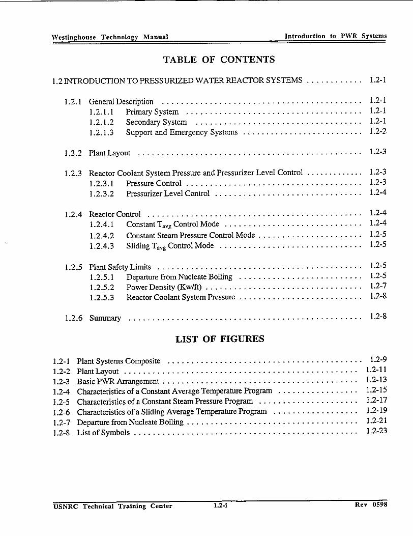
Westinghouse TechnoIo�y Manual Introduction to PWR Systems
TABLE OF CONTENTS
1.2 INTRODUCTION TO PRESSURIZED WATER REACTOR SYSTEMS ............
1.2.1 General Description .......................................... 1.2.1.1 Prim ary System ..................................... 1.2.1.2 Secondary System ................................... 1.2.1.3 Support and Emergency Systems ..........................
1.2.2 Plant Layout ...............................................
1.2.3 Reactor Coolant System Pressure and Pressurizer Level Control 1.2.3.1 Pressure Control .......................... 1.2.3.2 Pressurizer Level Control ....................
1.2.4 Reactor Control .................................. 1.2.4.1 Constant Tavg Control Mode ..................
1.2.4.2 Constant Steam Pressure Control Mode ........... 1.2.4.3 Sliding Tavg Control Mode ...................
1.2.5 Plant Safety Limits ................................ 1.2.5.1 Departure from Nucleate Boiling ............... 1.2.5.2 Power Density (Kw/ft) ...................... 1.2.5.3 Reactor Coolant System Pressure ...............
1.2.6 Summ ary ......................................
1.2-1
1.2-1 1.2-1 1.2-1 1.2-2
1.2-3
1.2-3 1.2-3 1.2-4
......... 1.2-4
......... 1.2-4
......... 1.2-5
......... 1.2-5
......... 1.2-5 ......... 1.2-5 ......... 1.2-7 ......... 1.2-8
......... 1.2-8
LIST OF FIGURES
Plant Systems Composite ...................... Plant Layout ...............................
1.2-3 Basic PWR Arrangement ..........................Characteristics of a Constant Average Temperature Program Characteristics of a Constant Steam Pressure Program .... Characteristics of a Sliding Average Temperature Program . Departure from Nucleate Boiling ................... List of Symbols ..............................
.... 1.2-9
. .. 1.2-11
... 1.2-13
... 1.2-15
... 1.2-17 ... 1.2-19 ... 1.2-21 ... 1.2-23
USNRC Technical Training Center 1.2-i Key U�Y�
1.2-1 1.2-2
1.2-4 1.2-5 1.2-6 1.2-7 1.2-8
Westinghouse Technology Manual Introduction to PWR Systems
............ Q
...........
...........
...............
...............
Rev 05518USNRC Technical Training Center 1.2-i

Westinghouse Technolo!y Manual Introduction to PWR Systems
1.2 INTRODUCTION TO PRESSURIZED WATER REACTOR SYSTEMS
Learning Objectives:
1. Define the following terms:
a. Average reactor coolant system temperature (Tavg),
b. Differential reactor coolant system tem
perature (AT),
c.' Departure from nu~leate boiling (DNB), d.' Departure from nucleate boiling ratio
(DNBR), e. Power density (Kw/ft), and f. Seismic Category I.
2. Explain why Tayg is programmed to increase
with an increasing plant load.
"3."'List two plant safety limits and explain the 'basis of each.
-4.' List, in flow path order, the major components in the:
a. Primary cycle and b. Secondary cycle.
1.2.1 General Description
1.2.1.1 Primary System
The composite flow diagram shown in Figure 1.2-1 illustrates the dual cycle nature of a PWR. The primary, cycle, or reactor coolant system
,(RCS), consists of: the reactor; where the heat from fission is transferred to the light water coolant; the steam generators, where hot reactor coolant is circulated through tubes to produce
,steam; and the reactor coolant pumps, which circulate the coolant through the heat transfer loops. The rated thermal output of a PWR is determined by the size of the reactor and the number of heat transfer loops in the primary system.
1.2.1.2 Secondary System
The secondary, or steam cycle, begins in the shell side of the steam generators, where the
incoming feedwaterdis boiled as it picks up heat -from contacting the 'U-tubes. containing -hot reactor coolant. These U-tubes provide the barrier between the primary -and secondary cycles.
Steam leaving the steam 'generators passes through steamline isolation valves and is directed to the high pressure section of the main turbine. After leaving the high pressure turbine, ,the low ,energy, moisture laden steam is routed -to a
moisture separator/reheater, where the excess
A pressurizer w r ( ) g g moisture is removeUanu a slal AalllULIL V Apressurizer water reactor (PWR) generating ,-superheat is applied by reheating the steam with
system is a dual 'cycle plant conisisting of a. 'osste isadult coo tsysteg o high energy steam from the main steam system. clos~d,' pressurized, rea•ctor coolant system• . . . ,
(primary) 'and 'a selfarate power conversion The dry, "-' . . . _ - Th dy reheated steam then enters the low
system (secondary) for the generation of electrici- pressure turbines, , where most of its remaining
ty. The use of a dual cycle keeps the potenitially ''energy is removed, and exits to the main con
radioactive reactor coolant separate from the main denser. Provisions are made to bypass the
turbine, condenser, and other secondary plant turbine and dump steam directly to the main
components. condenser under certain plant conditions.
- - - - - � nrnO
USNRC Technical Training Center 12-1 z�ev u�yo
Introduction to PWR Systems. Westinehouse ,Technology Manual
Rev u0598USNRC Technical Training Center . 1.2-1

Westnghuse echolog MaualIntroduction to PW. - 43.it
In the condenser, the, steam is condensed by passing over tubes containing condenser circulating water and is collected in the condenser hotwell. Condensate pumps take a suction on the hotwell and pump the water through the tube side of feedwater heaters to the suction of the main feedwater pumps.
The feedwater heaters are provided to increase plant efficiency. The main feedwater pumps discharge, through level control valves, into the steam generators, where the feedwater is boiled to produce steam, and the cycle begins again.
1.2.1.3 Support and Emergency Systems
Attached to each reactor coolant loop's cold leg is a nitrogen loaded accumulator, which will inject borated water into the RCS if, the RCS pressure boundary ruptures (loss of coolant accident or LOCA). When the pressure in the RCS drops below the pressure in the accumulators, the nitrogen will force the borated water into the RCS to provide water to cover and cool the core and boron (a neutron absorber) to keep the core shutdown.
The residual heat removal (RHR) system, located in the auxiliary building, serves two functions. The normal function is to remove the decay heat from the core after shutdown. This is accomplished by pumping the hot RCS water from the hot leg through a heat exchanger and back into the RCS via the cold leg. The accident function is to pump cool, borated water from the refueling water storage tank (RWST) into the RCS following a LOCA. It is a low pressure, high capacity system.
The safety injection system is an emergency system located in the auxiliary building that also provides for injection of borated water from the RWST into the RCS in the event of a LOCA. It has a smaller capacity but a higher discharge pressure than the RHR system.
The chemical and volume control system (CVCS) maintains the purity of the RCS by means of demineralizer beds that continuously purify a small letdown stream from the RCS. This purified water is returned to the RCS at a rate which is controlled to maintain the proper pressurizer level. A portion of the CVCS serves as a high pressure supply of borated water to the RCS in emergency situations.
In the event a LOCA does occur, the hot water from the RCS will spill out into the containment and flash to steam, raising the pressure in the containment building. The containment spray pumps will transfer water from the RWST to spray rings'iocated high inside containment. The cool water sprayed out into containment will quench the steam and return pressure inside containment within design limits. This prevents rupture of the containment building 'and the subsequent release of the contaminated water which had spilled from the RCS.
The component cooling water (CCW) system provides a cooling medium to various potentially radioactive components, such as heat exchangers, pump oil and seal coolers,'and fan units. It is a closed loop system and is cool~d by the service water sy~stem, which receives water from the river or lake, on which the plafit is located.
iecnnicai iraining Lenter Rev 0598
Westinghouse Technology Manual
USNRCI. lechnncal Iraining C~enter 1.2-2 Rev 0598
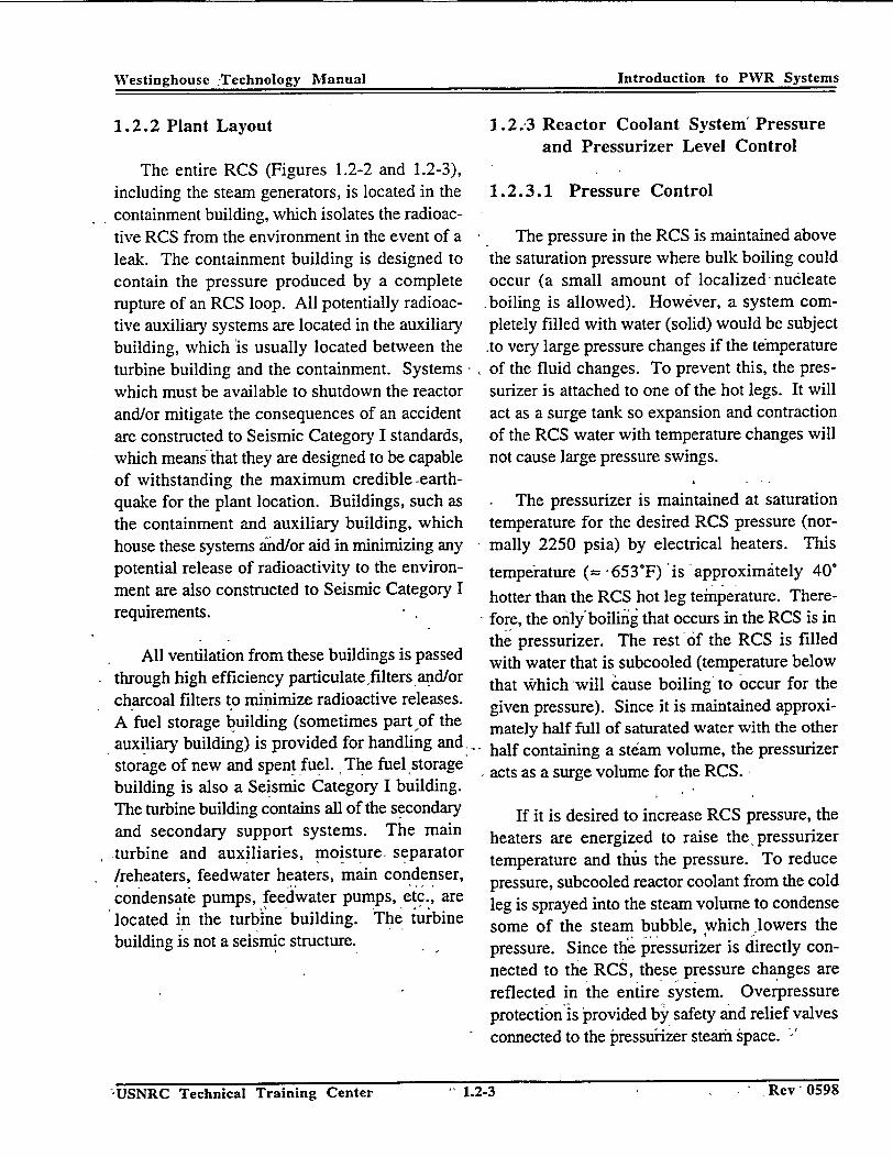
Westinghouse Technology Manual Introduction to PWR Systems
1.2.2 Plant Layout
The entire RCS (Figures 1.2-2 and 1.2-3), including the steam generators, is located in the containment building, which isolates the radioactive RCS from the environment in the event of a leak. The containment building is designed to contain the pressure produced by a complete rupture of an RCS loop. All potentially radioactive auxiliary systems are located in the auxiliary building, which is usually located between the turbine building and the containment. Systems which must be available to shutdown the reactor and/or mitigate the consequences of an accident are constructed to Seismic Category I standards, which means that they are designed to be capable of withstanding the maximum credible -earthquake for the plant location. Buildings, such as the containment and auxiliary building, which house these systems and/or aid in minimizing any potential release of radioactivity to the environment are also constructed to Seismic Category I requirements.
All ventilation from these buildings is passed through high efficiency particulate filters and/or charcoal filters to minimize radioactive releases. A fuel storage building (sometimes part of the auxiliary building) is provided for handling and storage of new and spent fuel. The fuel storage building is also a Seismic Category I building. The turbine building contains all of the secondary and secondary support systems. The main turbine and auxiliaries, moisture separator /reheaters, feedwater heaters, main condenser, condensate pumps, feedwater pumps, etc., are located in the turbine building. The turbine building is not a seismic structure.
1.2.'3 Reactor Coolant System' Pressure and Pressurizer Level Control
1.2.3.1 Pressure Control
The pressure in the RCS is maintained above the saturation pressure where bulk boiling could occur (a small amount of localized nucleate boiling is allowed). However, a system completely filled with water (solid) would be subject
.to very large pressure changes if the temperature of the fluid changes. To prevent this, the pressurizer is attached to one of the hot legs. It will act as a surge tank so expansion and contraction of the RCS water with temperature changes will not cause large pressure swings.
The pressurizer is maintained at saturation temperature for the desired RCS pressure (normally 2250 psia) by electrical heaters. This
temperature (- '653"F) is approximately 40°
hotter than the RCS hot leg temperature. Therefore, the only'boiling that occurs in the RCS is in the pressurizer. The rest of the RCS is filled with water that is subcooled (temperature below that Which will cause boiling- to occur for the given pressure). Since it is maintained approximately half full of saturated water with the other half containing a steam volume, the pressurizer acts as a surge volume for the RCS.
If it is desired to increase RCS pressure, the heaters are energized to raise the pressurizer temperature and thus the pressure. To reduce pressure, subcooled reactor coolant from the cold leg is sprayed into the steam volume to condense some of the steam bubble, which lowers the pressure. Since thle pressurizer is directly connected to the RCS, these pressure changes are reflected in the entire system. Overpressure protection is provided by safety and relief valves connected to the pressurizer steam space. -
-UNR ecnia Tanig ete..... rey u •- y IN--USNRC Technical Training Center -" 1.2-3
Westinghouse :Technology Manual Introduction to PWR Systems
- R~ev 0U518
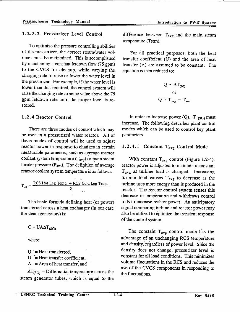
Westinghouse~~ TehooIMna ntrodluction to PWR' stepm
1.2.3.2 Pressurizer Level Control
To optimize the pressure controlling abilities of the pressurizer, the correct steam/water volumes must be maintained. This is accomplished by maintaining a constant letdown flow (75 gpm) to the CVCS for cleanup, while varying the charging rate to raise or lower the water level in the pressurizer. For example, if the water level is lower than that required, the control system will raise the charging rate to some value above the 75 gpm- letdown rate until the proper level is restored.
1.2.4 Reactor Control
There are three modes of control which may be used in a pressurized water reactor. All of these modes of control will be used to adjust reactor power in response to changes in certain measurable parameters, such as average reactor coolant system temperature (Tavg) or main steam header pressure (Pstm). The definition of average reactor coolant system temperature is as follows:
Tavg =RCS Hot Leg Temp. + RCS Cold Leg Temp. 2
The basic formula defining heat (or power) transferred across a heat exchanger (in our case the steam generators) is:
Q = UAAT(sG)
where:
Q Heat transferred, U '- Heat transfer coefficient, A Area of heatftransfer, and
AT(SG) = Differential temperature across the steam generator tubes, which is equal to the
difference between Tavg and the main steam temperature (Tstm).
For all practical purposes, both the heat transfer coefficient (U) and the area of heat transfer (A) are'assumed to be constant. The equation is then reduced to:
Q - AT(sG)
or Q -• Týg - T•t.
In order to increase power (Q), T (SG) must increase. The following describes plant control modes which can be used to control key plant parameters.
1.2.4.1 Constant Tavg Control Mode
With constant Tavg control (Figure 1.2-4), reactor power is adjusted to maintain a constant Tavg as turbine load is changed. Increasing turbine load causes Tavg to decrease as the turbine uses more energy than is produced in the reactor. The reactor control system senses'this decrease in temperature and withdraws control rods to increase reactor power. An anticipatory signal comparing tuirbine and reactor power may also be utilized to optimize the transient response of the control system.
The constant Tavg control mode has the advantage of an unchanging RCS temperature and density, regardless of power level. Since the density does not change, pressurizer level is constant for all load'conditions. This minimizes volume fluctuations in the RCS and reduces the use of the CVCS components in responding to the fluctuations.
USNRC Technical Training Center 1.2-4 Rev 0598
Westinghouse Technology Manual
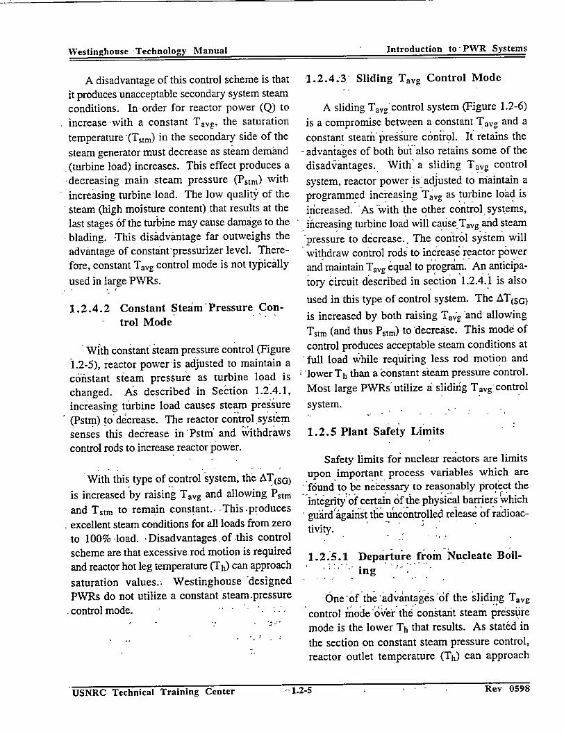
*Tphnla MV, __ 12 Introduction to- PWR -Systems
A disadvantage of this control scheme is that it produces unacceptable secondary system steam conditions. Inorder for reactor power (Q) to
increase with a constant Tavg, the saturation
temperature,'(Tstm) in the secondary side of the
steam generator must decrease as steam demand -(turbine load) increases. This effect produces a
,decreasing main steam pressure (Pstm) with
increasing turbine'load. The low quality of the
steam (high moisture content) that results at the
last stages 6f the turbine may cause damage to the blading. This disadvantage far outweighs the
advantage of constant -pressurizer level. There
fore, constant Tayg control mode is not typically
used in large PWRs.
1.2.4.2 Constant Steam'Pressure Control Mode
With constant steam pressure control (Figure 1.2-5), reactor power -is adjusted to maintain a
constant steam pressure as turbine load is changed. As described in Section 1.2.4.1, increasing turbine load causes steam pressure (Pstm) toI dcrease. The reactor control sy~stem
senses this dec'rease in 'Pstm and withdraws control rods to increase reactor power.
With this type of control system, the AT(sG)
is increased by raising Tayg and allowing Pstm
and Tstm to remain constant., This.produces
-excellent steam conditions for all loads from zero
to 100% -load. ,Disadvantages, of this control scheme are that excessive rod motion is required and reactor hot leg temperature (Th) can approach
saturation values.. Westinghouse designed PWRs do not utilize a constant steam .pressure
-control mode. ' - -
1.2.4.3 Sliding Tayg Control Mode
A sliding Tavg control system (Figure 1.2-6)
is a compromise between a constant Tavg and a
constant stearmipressure conirol. It retains the
- advantages of both but also retains some of the
disad'vantages. With' a sliding Tavg control
system, reactor power is-adjusted to maintain a
programmed increasing Tavg as turbine load is
increased. As -with the other control systems,
iicreasing turbine load will cause Tavg and steam
pressure to dgcrease. The control system will withdraw control rods to increase reactor power
and maintain Tavg equal to program. An anticipa
tory circuit described in section 1.2.4.1 is also
used in this type of control system. The AT(sG)
is increased by both raising Tavg -and allowing
Tstmn (and thus Pstm) to decrease. This mode of
control produces acceptable steam conditions at full load while requiring less rod motion and
lower Th than a constant steam pressure control.
Most large PWRs utilize a slidinig Tavg, control
system.
1.2.5 Plant Safety Limits
Safety limits for nuclear reactors are limits upon important process variables which are
'f6und to be necessary to reasonably protect the
"integrity of certain of the physical barriers 'which guard'against the uncontrolled release of radioactivity.
1.2.5.1 Departure from-Nucleate Boiling
One-of the advantages of the sliding Tavg
control mode ocVer the constant steam pressu-e
mode is the lower Th that results. As stated in
the section on constant steam pressure control, reactor outlet temperature (Th) can approach
z'�ev u�yo USNRC Technical Training Center 1.2-5
-"1.2-5USNRC Technical Training Center imev VZYO
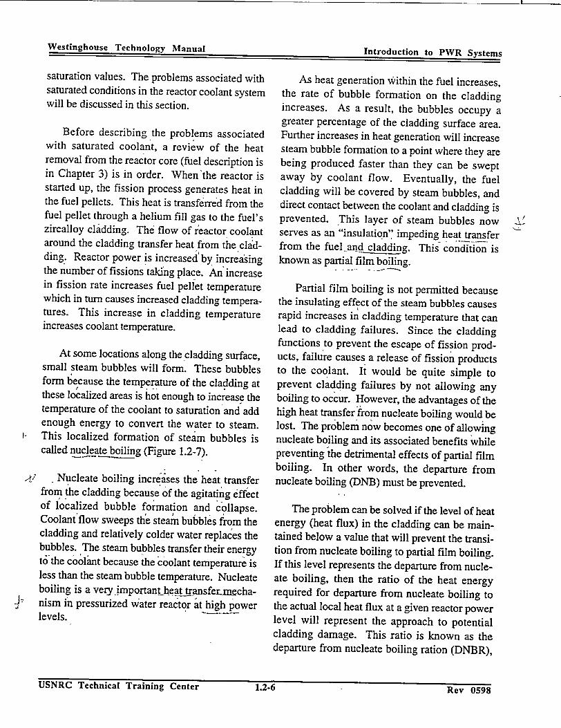
Westinghouse Technology Manual ction to PWR Systems
saturation values. The problems associated with saturated conditions in the reactor coolant system will be discussed in this section.
Before describing the problems associated with saturated coolant, a review of the heat removal from the reactor core (fuel description is in Chapter 3) is in order. When the reactor is started up, the fission process generates heat in the fuel pellets. This heat is transferred from the fuel pellet through a helium fill gas to the fuel's zircalloy cladding. The flow of reactor coolant around the cladding transfer heat from the cladding. Reactor power is increased by increasing the number of fissions taking place. An increase in fission rate increases fuel pellet temperature which in turn causes increased cladding temperatures. This increase in cladding temperature increases coolant temperature.
At some locations along the cladding surface, small steam bubbles will form. These bubbles form because the temperature of the cladding at these localized areas is hot enough to increase the temperature of the coolant to saturation and add enough energy to convert the water to steam. This localized formation of steam bubbles is called nucleate boiling (Figure 1.2-7).
,/ .Nucleate boiling increases the heat transfer from the cladding becauseI of the agitating effect of localized bubble formation and collapse. Coolantiflow sweeps the steam bubbles from the cladding and relatively colder water replaces the bubbles. The steam bubbles transfer their energy t6 the cooloant because the coolant temperature is less than the steam bubble temperature. Nucleate boiling is a very.important heat_transferjn=chanism in pressurized water reactor at high power levels.
As heat generation Within the fuel increases, the rate of bubble formation on the cladding increases. As a result, the bubbles occupy a greater percentage of the cladding surface area. Further increases in heat generation will increase steam bubble formation to a point where they are being produced faster than they can be swept away by coolant flow. Eventually, the fuel cladding will be covered by steam bubbles, and direct contact between the coolant and cladding is prevented. This layer of steam bubbles now serves as an "insulation" impeding heat transfer from the fuel-and cladding. This condition is known as partial film boiling.
Partial film boiling is not permitted because the insulating effect of the steam bubbles causes rapid increases in cladding temperature that can lead to cladding failures. Since the cladding functions to prevent the escape of fission products, failure causes a release of fission products to the coolant. It would be quite simple to prevent cladding failures by not allowing any boiling to occur. However, the advantages of the high heat transfer from nucleate boiling would be lost. The problem now becomes one of allowing nucleate boiling and its associated benefits while preventing the detrimental effects of partial film boiling. In other words, the departure from nucleate boiling (DNB) must be prevented.
The problem can be solved if the level of heat energy (heat flux) in the cladding can be maintained below a value that will prevent the transition from nucleate boiling to partial film boiling. If this level represents the departure from nucleate boiling, then the ratio of the heat energy required for departure from nucleate boiling to the actual local heat flux at a given reactor power level will represent the approach to potential cladding damage. This ratio is known as the departure from nucleate boiling ration (DNBR),
J1IN7DI`' rr 1. :Rev 0598
I
•-~~ #~a AL• UT.'t'..^,.i.,.
TT•I'•Dt nT• . : • ca -^ -- -- rining Uent.- ..2•-D

Westinghouse Technology Manual Introduction to PWR Systems
and for the puirposes of this discussion will be defined as:
"heat flux required for DNB to occur DNBR actual local heat flux
The reactor is assumed to be operating in or below the nucleaie boiling heat transfer region if DNBR is greater than one. At DNBR values less than one, partial film boiling is assumed to occur. At DNBR equal to one, great difficulty exists in determining exactly what will happen. Therefore, a value greater than one has been conservatively chosen as the DNBR limit. For Westinghouse designed PWRs, the minimum DNBR allowed is 1.3. Since maintaining DNBR within acceptable'limits is necessary for cladding integrity, it is designated as one of the plant's safety limits.
Thus fair in this discussion, the effect of "power level'(heat flux) and its influence on DNBR has been described. However, RCS pressure, temperature', flow, and the distribution of power also affect DNBR. If RCS pressure is decreased, the DNBR will decrease because less heat flux (lower power) is required to cause film boiling. Conversely, an increase in pressure will 'increase DNBR, and a higher heat energy is allowed. In summary,-DNBR is directly rportional to pressure.
The effect on DNBR of operating at a higher RCS temperature can be explained if one considers that the higher temperature represents a higher' heat energy in the coolant. Therefore, less heat energy is required to cause film boiling to occur. DNBR is inversely proportional to RCS temperature.
RCS flow facilitates heat removal from the cladding. A decrease in RCS flow results in a decrease in heat removal capability. A-decrease in heat removal reduces DNBR.
Modem PWR cores are about 12 feet high, and the distribution of power (heat flux) in the core has an important effect on DNBR. For example, if a greater portion of the total power is being produced in the bottom half of the core, the "cold" inlet coolant provides sufficient heat "removal to prevent DNBR problems. However, if a greater portion of the total power is being produced in the top half of the core, the DNBR will decrease due to the decrease in heat removal from the higher temperature coolant. In general, top peaked pow'er'distributions are worse from a DNBR standpoint.
To ensure that the DNBR'will remain at acceptable values, the combined'effects of total power, RCS pressure, RCS temperature, -RCS flow, and power distribution are monitored by the reactor protection systein (Chapter 12) to automatically shutdown (trip) the reactor if the limiting value of DNBR is approached. RCS differential temperature (T) is used by the reactor protection system as a diverse indication of power level for the DNBR-and Kw/ft reactor trips. RCS differential temperature is defined as follows:
'-AT = RCS hot leg temp. - RCS cold leg temp.
(NOTE: RCS AT- is not the same as AT(SG)
discussed in section 1.2.4)
1.2.5.2 Power Density (Kw/ft)
The second plant safety limit also deals with ,',heat energy production, and like DNBR, ensures
that the cladding barrier remains intact. This limit
USNRC Technical Training Center 1.2-7 Rev 05981.2-7
Westinihouse Technology Manual • - Introduction to PWR Systems
Rev 0598USNRC Technical Training Center
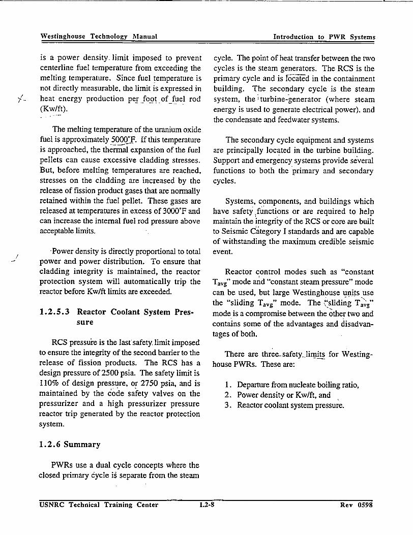
Westinghouse Technology Manual Introduction to PWR Systems
is a power density- limit imposed to prevent centerline fuel temperature from exceeding the melting temperature. Since fuel temperature is not directly measurable, the limit is expressed in
,_ heat energy production per foot of fuel rod (Kw/ft).
The melting temperature of the uranium oxide fuel is approximately 500*_F. If this temperature is approached, the thermal expansion of the fuel pellets can cause excessive cladding stresses. But, before melting temperatures are reached, stresses on the cladding are increased by the release of fission product gases that are normally retained within the fuel pellet. These gases are released at temperatures in excess of 3000*F and can increase the internal fuel rod pressure above acceptable limits.
Power density is directly proportional to total -• power and power distribution. To ensure that
cladding integrity is maintained, the reactor protection system will automatically trip the reactor before Kw/ft limits are exceeded.
1.2.5.3 Reactor Coolant System Pressure
RCS pressure is the last'safety, limit imposed to ensure the integrity of the second barrier to the release of fission products. The RCS has a design pressure of 2500 psia. The safety limit is 110% of design pressure, or 2750 psia, and is maintained by the code safety valves on the pressurizer and a high pressurizer pressure reactor trip generated by the reactor protection system.
1.2.6 Summary
PWRs use a dual cycle concepts where the closed primary cycle ig separate from the steam
cycle. The point of heat transfer between the two cycles is the steam generators. The RCS is the primary cycle and is loc•-ed in the containment building. The-secondary cycle is the steam system, the turbine-generator (where steam energy is used to generate electrical power). and the condensate and feedwater systems.
The secondary cycle equipment and systems are principally located in the turbine building. Support and emergency systems provide several functions to both the primary and secondary cycles.
Systems, components, and buildings which have safety functions or are required to help maintain the integrity of the RCS or core are built to Seismic Category I standards and are capable of withstanding the maximum credible seismic event.
Reactor control modes such as "constant Tavg" mode and "constant steam pressure" mode can be used, but large Westinghouse units use the "sliding Tavg" mode. The "'sliding Tavg"
mode is a compromise between the other two and contains some of the advantages and disadvantages of both.
There are three- safety_ limits for Westinghouse PWRs. These are:
1. Departure from nucleate boiling ratio, 2. Power density or Kw/ft, and 3. Reactor coolant system pressure.
USNRC Technical Training Center 1.2.8 Rev 0598Rev 0598
Westinghouse Technology Manual Introduction to PWR Systems
USNRC Technical Training Center 1.2-8
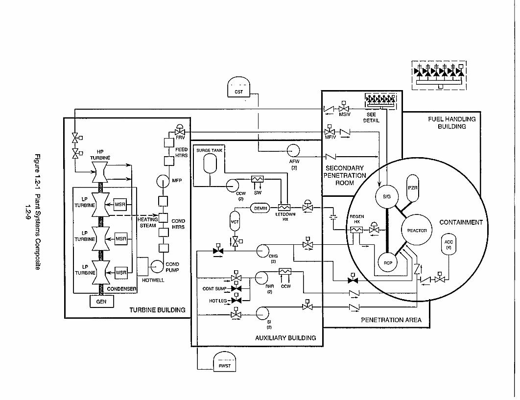
-I
CST
21
U) CA
0
3 0 Un.
CD
I', CD

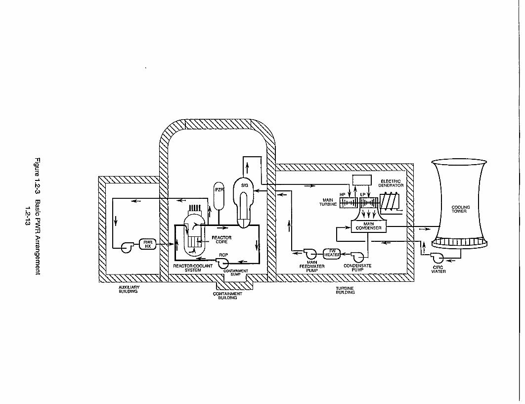
ca 0
-U.
CA)

PRESSURIZER
POWER OUTPUT
Figure 1.2-4 Characteristics of a Constant Average Temperature Program 1.2-15
w
U) (n w a
w (w I-
HOT ZERC POWER

1095-3
PRESSURIZER
5 60 OTc
POWER OUTPUT
Figure 1.2-5 Characteristics of a Constant Steam Pressure Program 1.2-17
D.
U)
ILL
HOT ZERO POWER
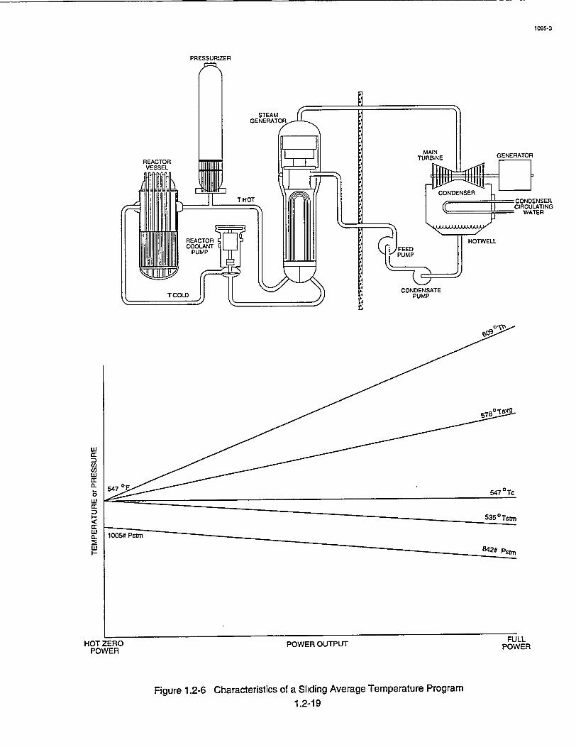
1095-3
PRESSURIZER
STEAM GENERATOR
MAIN
REACTOR TURBINE GENERATOR
VESSEL .
CCONDENSER T. THOT CO D NS RCONDENSER
S~CIRCULATING "WATER
CONDENSATE T COLD PUMP
rA
w q: S~535 o Tstm
HOT ZERO POWER OUTPUT POWER POWER
Figure 1.2-6 Characteristics of a Sliding Average Temperature Program 1.2-19
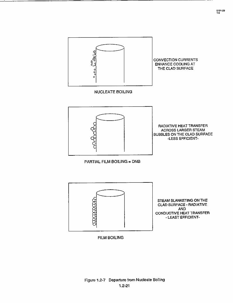
90
0
0 C 0
NUCLEATE BOILING
10
PARTIAL FILM BOILING = DNB
CONVECTION CURRENTS ENHANCE COOLING AT
THE CLAD SURFACE
RADIATIVE HEAT TRANSFER ACROSS LARGER STEAM
BUBBLES ON THE CLAD SURFACE -LESS EFFICIENT
STEAM BLANKETING ON THE CLAD SURFACE - RADIATIVE
AND CONDUCTIVE HEAT TRANSFER
- LEAST EFFICIENT-
FILM BOILING
Figure 1.2-7 Departure from Nucleate Boiling 1.2-21
0191-29 1-8

-I>K - Manually Operated Valve
-t1- Air Operated Valve
41-Motor Operated Valve
4F Solenoid Operated Valve
-N Check Valve
T'1- Relief Valve
SThree-Way Valve (Lower port shown closed)
-] An- Butterfly (Damper) Valve
41-Needle (Throttle)Valve
- 1 Diaphragm Valve
4-Valve Normally Closed
- Valve Normally Open
_2i.
c
0
Cr,
0 0) o,
-AI
9t~t -t1::::3
Centrifugal Pump
Positive Displacement Pump
Pressure Breakdown Orifice
Venturi Nozzle
Cooler or Heat Exchanger
Temperature Transmitter
Pressure Transmitter
Level Transmitter
Flow Transmitter
Meter or Gage
Logic Symbol (AND box) 2 or 4 available inputs must be present to produce an output
Logic Symbol (OR box) Any one of several available inputs will produce an output
Logic Symbol (NOT box) Input present produces no output, no input produces an output
rI:
NO
NC
Bistable (Trips on increasing input signal)
Bistable (Trips on decreasing input signal)
Summing Unit (Algebraically adds all inputs)
Isolation Amplifier (1/I amplifier)
Contact Pick-up Relay
Contacts (normally open)
Contacts (normally closed)
Transformer
Disconnect Switch
Circuit Breaker (normally open)
Circuit Breaker (normally closed)
Transfer Switch
Battery
Diode

Westinghouse Technology Manual
Chapter 2.0
Reactor Physics Review

Westinghouse Technology Manual Reactor Physics
TABLE OF CONTENTS
2.0 REACTOR PHYSICS .........................
2.1 Fission Process ...........................
2.2 Neutron Multiplication .......................
2.3 Reactivity and Reactivity Coefficients .............
2.4 Neutron Poisons ...........................
2.5 Shutdown Margin ..........................
LIST OF FIGURES
2-1 Moderator Temperature Coefficient ........ 2-2 Doppler Temperature Coefficient .......... 2-3 Power Coefficient .................... 2-4 Power Defect ....................... 2-5 Differential and Integral Rod Worth ........ 2-6 Xenon Transients ....................
USNRC Technical Training Center 2-i Key tJOY�
2-1
2-1
2-1
2-2
2-4
2-4
.... 2-7 .... 2-9 ... 2-11 ... 2-13 ... 2-15 ... 2-17
Rev U0698
Westinghouse Technology Manual Reactor Physics
................. o......
.......................
.......................
.......................
... o...................
.......................
USNRC Technical Training Center 2-i
WetnhueTcnlg aul10LvlOjcie
2.0 REACTOR PHYSICS
Learning Objectives:
1. Define the following terms:
a. Keff, b. Reactivity, c. Critical, d. Supercritical, e. Subcritical, f. Moderator temperature coefficient, g. Fuel temperature coefficient (Doppler), h. Void coefficient, i. Power coefficient, j. Power defect, and k. Neutron poison.
2. List two controllable and one uncontrollable neutron poison.
Westinghouse Technology Manual 100 Level Objectives
Westinghouse Technology Manual Reactor Physics
2.0 REACTOR PHYSICS
Learning Objectives:
1. Define the following terms:
a. b. C. d. e. f.
g. h. i. j.
"* k.
Keff, ,
Reactivity, Critical, Supercritical, Subcritical, Moderator temperature coefficient, "Fuel temperature coefficient (Doppler), Void coefficient, Power coefficient, Power defect, and
"Neutron poison.
"2'. List two controllable and one unc6ntrollable neutron poison.
2.1 Fission Process
Nuclear fission is the splitting of a large nucleus into two or more small nuclei and the release of a large amount of energy. The fission is triggered by absorption of a slow neutron by the nucleus, and among the fission products are several fast neutrons. If one of the fast neutrons is slowed down and absorbed by another fissile nucleus, a chain :reaction can be maintained. Neutrons from fission are fast, and the probability that they can cause a fission is.low. The probability can be increased by slowing down the neutrons. Thisis done with a moderator. In a pressurized water reactor, the moderator is water. The nuclei, which are the products of the fission process, are usually radioactive, decaying by beta decay. There is energy released by these decays which will continue after fission has ceased. This energy release is called decay heat and is a very important concept, because decay heat will
continue for- an indefinite period of time after reactor shutdown. For this reason, there must be "not only systems to shut the reactor down, but also systems to remove decay heat.
-2.2 Neutron Multiplication
Neutrons are produced from fission,'and the absorption of a neutron-:causes fission. The average time between fissions that produce "neutrons is called a generation. During a generation, neutrons are being slowed down by the moderator. There are several possible 'events that can happen to aneutron in addition' to causing fission. It is possible for the neutron to leak out of the reactor or be absorbed by material other than fuel. Any material which will absorb a neutron and will not fission is a neutron poison. Since the average numberof neutrons produced by a fission is about 2.5, and only one has to be absorbed and cause fission to sustain a chain reaction, the reactor is controlled by controlling the number of neutrons out of the 2.5 that will cause fission.
If the number of- neutrons produced by fission in one generation is divided by the number, produced in the previous generation, the
-,quotient is called the effective neutron multiplication factor (Kerr). Expressed in equation form, Keff would be: .
Number of neutrons in present generation Number of neutrons in previous generation
If Keff -is equal to -one, - then the neutron population is constant, and tlhe reactor is said to be critical. If Keff is larger than one, the reactor is iupeicritical: -With Keff less than'one, the
- reactor is subcritical. Sifnce power is proportion, al to neutron population, when the reactor*is
.critical, power is constant.-
USNRC Technical Training Center 2-1 Rev 0698'USNRC Technical Training Center
Westinghouse Technology Manual Reactor Physics
2-1 Rev 0698

Westnghuse echolog MaualReactor -Phvsics
To control Keff and therefore control the reactor, several design and operating parameters are used. There will always be some leakage out of the core, which is primarily a function of size and shape of the core. There will be non-fission absorption in the moderator, structural material, and even in the fuel. Control rods made of neutron poison material are inserted into or withdrawn from the core to change power.
There is a special situation that exists when the reactor is operating at the lowest power levels, which might appear to contradict some of the previous statements about -Keff and the neutron population. It is called subcritical multiplication and is caused by the presence of source neutrons. Source neutrons do not come from fission, but can cause fission. They usually come from materials put into the core to give the nuclear instruments a reliable background signal during startups. If the reactor is subcritical (Kff < 1.0) and there are no source.neutrons, the neutron population would always be decreasing, but never get to zero. There are enough losses in the neutron life cycle that there is less than one of the 2.5 neutrons produced that survive to cause another fission. But, if neutrons are introduced into the cycle from another source, the neutron population will reach an equilibrium when the source makes up for the losses., If Kcff is then increased, the neutron level will increase, because the losses decreased and there was an excess of source neutrons. A new-equilibrium neutron level will be reached.
2.3 Reactivity and Reactivity Coefficients
Keff is seldom used in commercial nuclear
power. The term used is reactivity (p). Reactivity can be defined as the measure of the deviation from criticality. Reactivity is related to Keff by
the equation:
Keff- 1 P Ke-l
Reactivity is a unitless number. Westinghouse has attached a unit of convenience (pcm) to the number. PCM is an abbreviation for percent millirho. The values of reactivity range in the order of 10-5. Rather than use exponents, Westinghouse chose to use pcm as the basic unit of reactivity. All other commercial vendors use K/K as the basic unit of reactivity. A reactivity of 0.001 would be expressed as 100 pcm. When a reactor is exactly critical (Keff = 1), reactivity is zero. A supercritical reactor has a positive reactivity, and a subcritical reactor has a negative reactivity. When a reactor is supercritical or subcritical and the reactivity is constant, the power change is exponential. The rate is described by the term startup rate (SUR). Power is given by the equation:
p = po 1 0(SUR)(t)
where Po is power at t = 0 and SUR is in decades per minute (DPM). A decade is a factor of 10. Time is in minutes.'
When parameters such as temperature, pressure, and boron concentration change, there is a corresponding change in core reactivity. The reactivity coefficient for a parameter is the change in reactivity caused by a unit change in the parameter. In equation form:
Ap ax= AX
where X is a parameter, and ax is its reactivity
coefficient.
USNRC Technical Training Center 2-2 Rev 0698Rev 0698
Westinghouse Technology Manual Reactor -Physics
USNRC Technical Training Center 2-2
Westinahouse Technoloev ManualRecoPhss
There are many reactivity coefficients, but this discussion will be limited to the few large, important ones. The first is the moderator
-temperature coefficient (MTC). MTC is defined as the change in reactivity per 'F change in
moderator temperature and is expressed iniunits
of pcm/°F., -There are several factors which
determine the magnitude and sign of the MTC.
The water flowing through the core is the moderator, but it also acts as a poison. It has boric acid
'dissolved in it for reactivity control., With no
boric acid, MTC would always be negative. -This
means that as moderator temperature increases, it: 'expands and there is less moderator in the core, which adds' negative reactivity to the core.
Figure 2-1 shows that for no boron (0 ppm), the
MTC is more negative at high temperature: This
"is because water expands more per degree at high
temperatures than at low 'temperatures. When there is boron in the water, there is an opposite effect added. When temperature rises and the water expands, there is less moderator in the core
(negative reactivity), but there is also less boron -(positive reactivity).
'Therefore' the addition of boron causes MTC
to be less negative. Too much boron could cause
stable for other reasons, but a positive MTC is generally not allowed at high power levels.
Another important coefficient is the fuel
temperature coefficient, or doppler coefficient.
This effect is due to absorption of neutrons in the fuel, primarily U-238, with'no~fission.- The absorption rate depends on the nucleus and neutron energy, which is a function of the fuel temperature. As fuel temperature increases, more
neutrons are captured nonproductively (no
fission) by the fuel. As seen in Figure -2-2, the doppler coefficientvis always negative, but less
negative at higher fuel temperature. This effect is related to the fuel pellet size:. The doppler coefficient is larger in magnitude than MTC,-so it is more responsible for inherent stability., Doppler is also faster acting because fuel temperature
changes before moderator temperature on a
power rise. This is important in accident analysis. ' '
The void coefficient is relatively small and is due to a small amount of boiling that occurs on the fuel clad. More boiling means less moderator
-,'in the core.. The effect could be positive or negative, but it is generally slightly negative.
MTC to be positive.- It is desirable to have a' negative MTC for reactor stability. If we ignore ' The ,power' coefficient is a combination of
other effects, a decrease in secondary power, MTC, doppler, and void'coefficients. As seen in
(load) would cause an increase in coolant (mod-, 'Figure' 2-3, it is always negative; -but more
erator) temperature. With a negative MTC,- ,,,negative at end of life (EOL) due to less boron
reactivity would decrease (become negative), and and more negative MTC. There isless boron at
reactor power would decrease, following load. EOL, because it is taken out as fuel bums out and
When reactor power follows load, the reactor is 1. less.negative reactivity is needed. Instead of
said to be inherently stable. ',using fuel or moderator temperature as the
parameter, power level -is used,--because it is
"-With a positive MTC, the moderator tempera- 'easier for operations.
ture increase would cause reactivity to increase, ' ,
"reactor power would increase, and the reactor .' More important to an operator than power
would be unstable. If we take into account other coefficient is power defect. It is the integrated
effects, we would find that the reactor is really, power coefficient using zero power as the refer-
KeV UOY� USNRC Technical Training Center 2-3
2-3USNRC Technical Training Center
I Reactor Physics
-Rtev 0698•
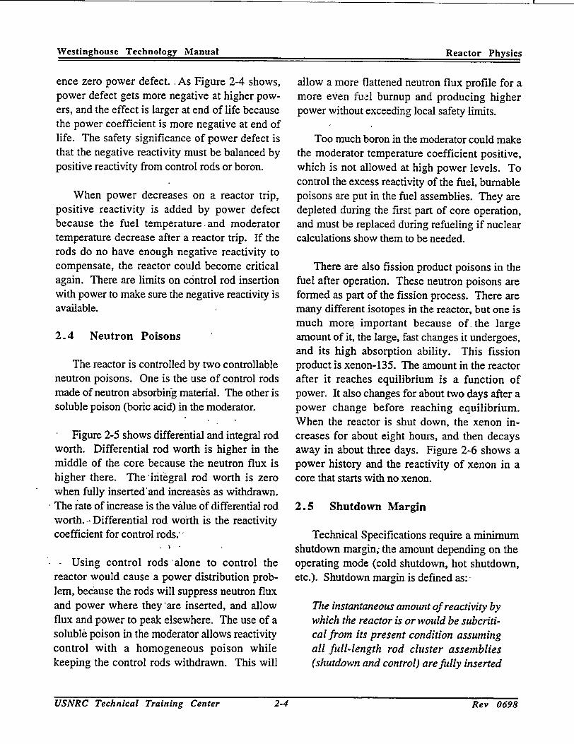
Westinghouse Technology Manual Reactor Physics
ence zero power defect. As Figure 2-4 shows, power defect gets more negative at higher powers, and the effect is larger at end of life because the power coefficient is more negative at end of life. The safety significance of power defect is that the negative reactivity must be balanced by positive reactivity from control rods or boron.
When power decreases on a reactor trip, positive reactivity is added by power defect because the fuel temperature and moderator temperature decrease after a reactor trip. If the rods do no have enough negative reactivity to compensate, the reactor could become critical again. There are limits on control rod insertion with power to make sure the negative reactivity is available.
2.4 Neutron Poisons
The reactor is controlled by two controllable neutron poisons. One is the use of control rods made of neutron absorbing material. The other is soluble poison (boric acid) in the moderator.
Figure 2-5 shows differential and integral rod worth. Differential rod worth is higher in the middle of the core because the neutron flux is higher there. The initegral rod worth is zero when fully inserted'and increases as withdrawn. The rate of increase is the vfdue of differential rod worth. Differential rod woith is the reactivity coefficient for control rods.''
- Using control rods-alone to control the reactor would cause a power distribution problem, because the rods will suppress neutron flux and power where they-are inserted, and allow flux and power to peak elsewhere. The use of a soluble poison in the moderator allows reactivity control with a homogeneous poison while keeping the control rods withdrawn. This will
allow a more flattened neutron flux profile for a more even fuel burnup and producing higher power without exceeding local safety limits.
Too much boron in the moderator could make the moderator temperature coefficient positive, which is not allowed at high power levels. To control the excess reactivity of the fuel, burnable poisons are put in the fuel assemblies. They are depleted during the first part of core operation, and must be replaced during refueling if nuclear calculations show them to be needed.
There are also fission product poisons in the fuel after operation. These neutron poisons are formed as part of the fission process. There are many different isotopes in the reactor, but one is much more important because of the large amount of it, the large, fast changes it undergoes, and its high absorption ability. This fission product is xenon-135. The amount in the reactor after it reaches equilibrium is a function of power. It also changes for about two days after a power change before reaching equilibrium. When the reactor is shut down, the xenon increases for about eight hours, and then decays away in about three days. Figure 2-6 shows a power history and the reactivity of xenon in a core that starts with no xenon.
2.5 Shutdown Margin
Technical Specifications require a minimum shutdown margin; the amount depending on the operating mode (cold shutdown, hot shutdown, etc.). Shutdown margin is defined as:
The instantaneous amount of reactivity by which the reactor is or would be subcritical from its present condition assuming all full-length rod cluster assemblies (shutdown and control) are fully inserted
VSNRC Technical Training Center 2-4 Rev 0698
Westinghouse Technology Manual Reactor Physics
USNRC Technical Training Center 2-4 Rev 0698
Westinghouse Technology Manual Reactor Physics
except for the single rod cluster assembly of highest reactivity worth which is assumed to be fully withdrawn.
The shutdown margin requirement is based on the ability to make the reactor subcritical from all operating conditions and to prevent inadvertent criticality from a shutdown condition.
During shutdown conditions, the actual shutdown margin can be calculated by performing a reactivity balance. During power operations, the available shutdown margin can be calculated by determining how much reactivity would be added by inserting all but the most reactive rod and by the temperature changes of the fuel and moderator. Consider that the plant is operating at full power with reactivity equal to zero (critical). A reactor trip will drive the power to no load and fuel temperature and moderator temperature both decrease, adding positive reactivity. The rods dropping will add negative reactivity.
If the rods do not have enough negative reactivity to exceed the positive reactivity from the temperature decrease, the reactor will not remain shutdown. In order to be sure the rods have enough negative reactivity, they are operated above the rod insertion limit, which is a function of power. As power increases, the rod insertion limit increases, so that rods must be further withdrawn to maintain a minimum available shutdown margin.
USNRC Technical Training Center 2-5 Rev U69�Rev 0698
Westinghouse Technology Manual Reactor Physics
USNRC Technical Training Center 2-5
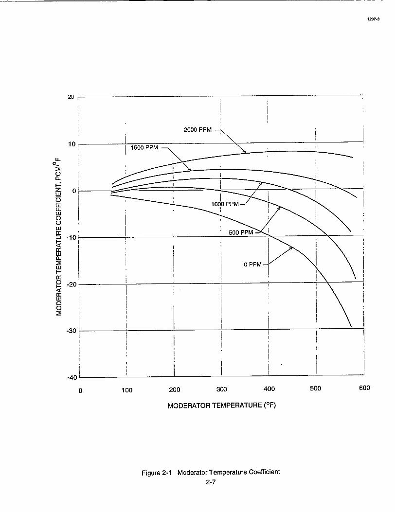
200 300 400
MODERATOR TEMPERATURE (OF)
Figure 2-1 Moderator Temperature Coefficient 2-7
1297-3
20
10
L
01
0~
z
LL L.U
0 0 u.I a: D -10Iw L.
0 -20 I-u
0
-30
-40
0 100 500 600

1095-3
-.0012 (-1.2pcm/F)I
600 800 1000 1200 1400 1600
EFFECTIVE FUEL TEMPERATURE ('F)
Figure 2-2 Doppler Temperature Coefficient, BOL and EOL 2-9
-0
z LL
0
LL
w
0 0
.<] or
D I
0~
0
LU
I.I
LU
aa-,0 rr
-.0013
-.0014
-.0015
-.0016
-.0017
-.0018
-.0019400 1800

-. 012 (-12 pcmf% power)
-.014
I.z
LL ILL IU
LU
0
0_ 0~ a..
II--
0 0- -.016
CD
-.018
I: 'O
-0EOL
-.022
0 20 40 60POWER LEVEL (PERCENT FULL POWER)
Figure 2-3 Power Coefficient 2-11
1095-3
80 100
- n•N

-0.5
S-2.0I
I-2. o o Il
I.
0
-2.0L
-2.5L (-2500 pcm)0
20 40 60 POWER LEVEL (PERCENT FULL POWER)
Figure 2-4 Power Defect
2-13
1095-3
80 100
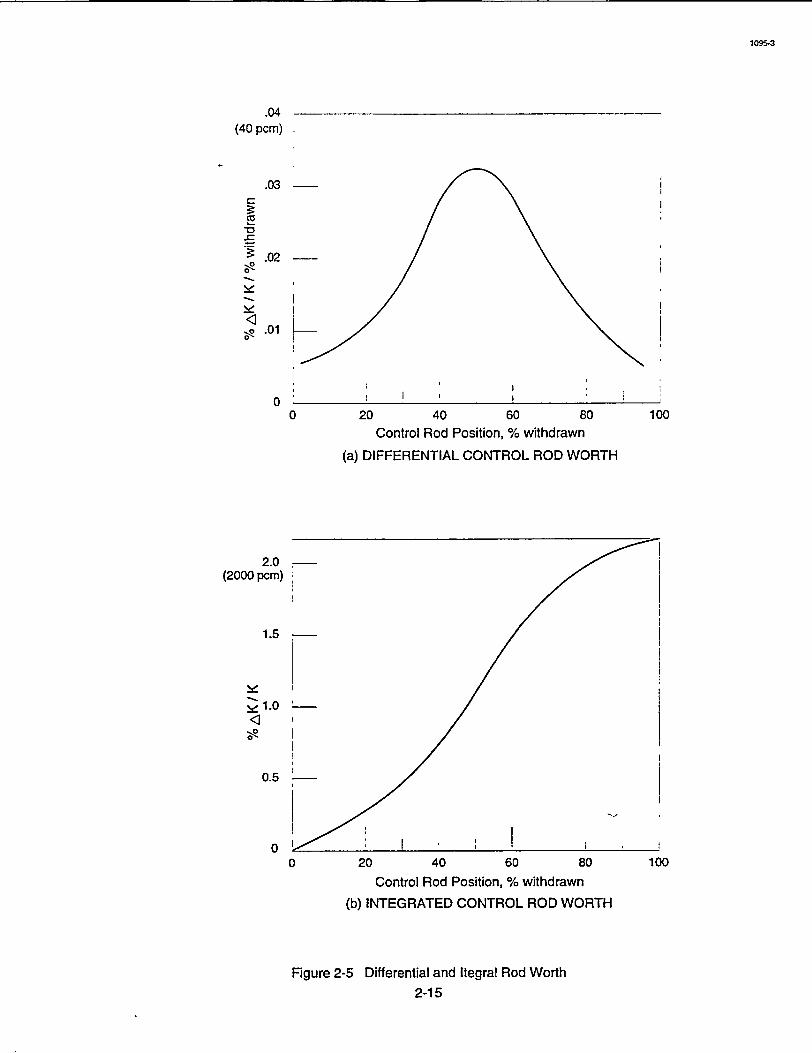
1095-3
.04 (40 pcm)
.03
-0
.02
.01
00 20 40 60 80 1
Control Rod Position, % withdrawn
(a) DIFFERENTIAL CONTROL ROD WORTH
00
2.0 (2000 pcm)
1.0
0.5
00 20 40 60 80 1
Control Rod Position, % withdrawn
(b) INTEGRATED CONTROL ROD WORTH
00
Figure 2-5 Differential and Itegral Rod Worth 2-15
d
<3
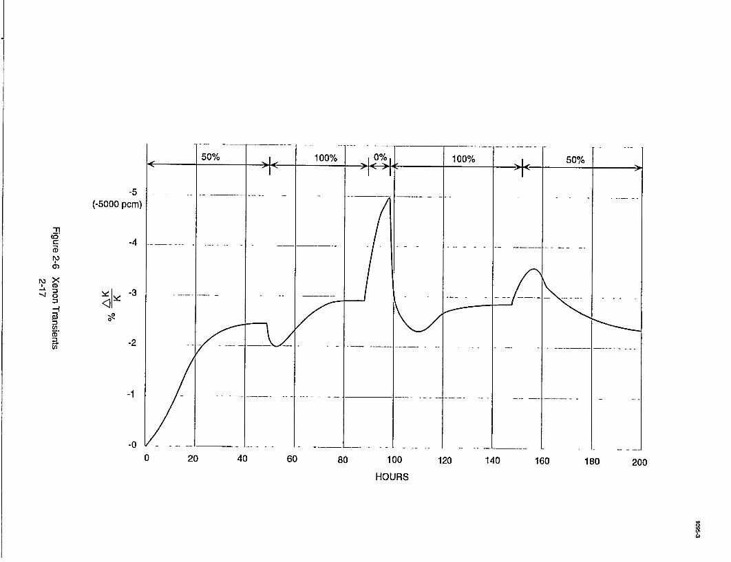
-5 (-5000 pcm)
to
4 Y_ _3
00)
en
,4 o <• • -3 . . ... . ..-*
.0
S20
"-0 ---. . - _ _ .. ..- -
0 20 40 60 80 100 120 140 160 180 200
HOURS
Westinghouse Technology Manual 100 Level Objectives
3.1 REACTOR CORE AND VESSEL CONSTRUCTION
Learning Objectives:
1. State the purpose of the following major reactor vessel and core components:
a. Internals support ledge, b. Thermal shield, c. Secondary support assembly, d. Fuel assembly, e. Control rod, f. Upper and lower core support structures, g. Primary and secondary source assemblies, h. Burnable poison rod assemblies, and i. Thimble plug assemblies.
2. Describe the flow path of reactor coolant from the inlet nozzles to the outlet nozzles of the reactor vessel.

-hti~ouse Technology Manual RatrCr n eslCntuto
'3.1 REACTORCORE AND VESSEL CONSTRUCTION
'Learning Objectives:
1. State the purpose of the following major
"* reactor vessel and core components:
a. Internals support ledge, b. Thermal shield, 'c. Secondary support assembly, d ' Fuel assembly, e. Controlirod,, f. Upper and lower core support structures, g. Primary anid' secondary source'assem
blies; h. Burnable poison rod assemblies,'and i. Thimble plug assemblies.
2; Describe the flow path of reactor 'coolant from the inlet nozzles to the outlet nozzles of 'the reactor vessel.
3. List the basic structural components of a fuel assembly.
3.1.1 Introduction
The purpose of the reactor core is to generate heat which is transferred to the steam geneiators where steam is produced for the turbine genera
tor. The core is located in the reactor vessel and is composed of'193 fuel assemblies. 'The fuel
pellets and any fission product material is contained within the fuel assembly cladding. The cladding provides the first barrier to the acciden
- tal release of radioactive material to the envirohment. Any breach of the'fuel cladding will
•be contained within the boundary of the sur.rounding reactor coolant system, ,which is -the
Ssecond barrier to a radioactive release (with the containment building being the third barrier). ,
3.1.2 Reactor
-3.1.2.1 Reactor Vessel
The reactor core and all associated support and alignment devices are contained in the reactor vessel (Figure 3.1-1). The reactor vessel is comprised of a cylindrical shell with a hemispherical bottom head and a removable, flanged
Shemispherical top head. Nozzles are also provid'ed for reactor coolant flow into and out of the ivessel. The reactor vessel and head are con
structed of manganese-molybdenum steel \vith all
surfaces in contact with -reactor coolant clad in 'stainless steel. When set into the containment building, the weight of the reactor vessel, head, and all internal components is supported bypads welded to the vessel nozzles.' The pads then bear
on reactor support assemblies attached to the concrete primary (biological) shield wall surrounding the-reactor.
3.1.2.2 Reactor Core and Vessel Internals
-The -reactor core" and vessel internals 'are
shown in crbss-section 'in Figure 3.1-2 and in elevation in Figures 3.1-3 and 3.1-4.- The core,
-consisting of fuel assemblies, control- r6ds, source rods, 'burnable 'poison rods,''and "guide thimble plugging devices,- provides the heat
Ssource and the means to control it.
"The internals, consisting of theupper and lower core support structures, are designed to
"-,support, align, andguide the 'coie components, direct the coolant flow to and from the core components, and to support and guide the incore instrumentatidii. 'The' fuel assemblies consist of a •inumber of zircalloy-4 cladding tubes; filled with slightly enriched uranium dioxide pellets,.pres"surized with heliurn, and seal welded to'encapsu-
USNRC Technical Training Center '-3.1-1 zi�ev u�yo
Reactor C6re a'nd Vessel Constru'ctionWestinfhueTcnooyMna
I RKev 0598USNRC Technical Training Center "ý 3.1-1
Westighoue, Tchno~g~ AnualReactor Core and Vessel Conncft ti~,
late the fuel. The construction of all fuel assemblies is identical except that different enrichment pellets are loaded into certain assemblies dependent upon the location of that assembly in the core.
3.1.2.3 Reactor Internals
The internals are designed to withstand the forces due to weight, pre-load of fuel assemblies, control rod dynamic loading, vibration, and loss of coolant accident (LOCA) blowdown coincident with earthquake accelerations. Under these loading conditions, including conservative effects of design earthquake loading, the structures satisfy stress values prescribed in the ASME Nuclear Vessel Code. In this discussion, the components of the reactor, internals will be divided into two parts:
a. The lower core support structure and
b., The upper core support structure.
The lower core support structure consists of the core barrel, the core support forgings, the diffuser plate, the lower core plate and support columns, the secondary support assembly, and the core baffle-former assembly. (Figure 3.1-5). All of the major material for this structure is type 304 stainless steel. The core barrel is constructed in several sections. The upper core barrel, consisting of the flange and outlet nozzle sections, is welded to the lower core barrel. The core support forging is then welded to the lower core barrel to complete construction of the core barrel.
- A one piece cylindrical thermal shield is attached to the core barrel. The purpose of this shield is to attenuate fast neutrons that would otherwise excessively irradiate and embrittle the
vessel walls.- Also, the thermal shields- will attenuate the gamma radiation from the reactor core to minimize the irradiation damage to the reactor vessel. The irradiation specimen guides are attached to the thermal shield and contain samples of reactor vessel metal which can be recovered at periodic intervals after irradiation to analyze the effects of radiation on the material properties of the specimen.
The lower core plate is bolted and welded to the inside circumference of the lower core barrel. This lower core plate is a two inch thick plate through which four flow distribution holes for each fuel assembly are drilled. Also provided are fuel assembly locating pins (two for each assembly) which are inserted into this plate.
Core support columns are placed between the lower core plate and the core support forging to provide stiffness and transmit the weight of the core to the core support forging. Positioned between the lower core plate and the core support forging is the diffuser plate, which is a perforated plate designed to uniformly diffuse the coolant flowing into the core.
Located inside the core barrel and above the lower core plate is the baffle-former plate assembly. It is this assembly which actually forms' the boundary for the reactor core. All fuel assemblies will be placed inside the baffle assemblies and rest on the lower core plate.
The lower core support package is lowered into the reactor vessel and is supported by the core barrel flange, resting on the internals support ledge of the reactor vessel (Figure 3.1-4). Radial alignment is provided at the bottom of the core barrel a by key and keyway arrangement, A key on the core barrel slides into a keyway fastened to the reactor vessel wall. This design
Ttc��1T� ,�. '7*� � �, - - * -' -� - - -u3r�r�x. iecnrncai iraining Lenter Rev 05983.1-2 Rev 0598
I
Westinghouse, Technology ana|
USINKC. lechnncal training Center
* Westinghouse Technology Manual Reactor .Core and Vessel Construction
allows radial and'axial expansion of the core barrel but limits transverse movement.
If the core barrel flange should fail, a secondary support assembly is provided. The secondary support assembly (or "drop shoe") consists of cylindrical energy absorbers which limit the
* distance the core will fall such that the withdrawn 'c6trol rods are still aligned with their respective "fuel assemblies. These energy absorbers simply contact the-bottom of the reactor vessel to limit the distance the core can drop.
The lower core support structure also serves to direct and control coolant flow. Inlet coolant flows from the reactor vessel inlet nozzles, down
,the annulus between the core barrel and Vessel wall (on both sides of the thermal shield), and into the plenum at the bottom of the reactor vessel (Figure 3.1-6). 'It then- flows -up through the lower core support-forging, the diffuser plate,
'and lower core plate. The flow holes in these platesare arranged to give a very even entrance flow distribution to the 'core. After passing through the core (fuel assemblies), the coolant enters the area of the upper support structure and flows radially to the core barrel outlet nozzles and out the reactor vessel outlet nozzles.
A small portion of the- flow 'also' flows -betweeri-the baffle-former- assembly and core barrel to provide additional cooling of the barrel.
:-Similarly, a small amount of the inlet 'flow is directed to the vessel head -plenum to provide cooling'and mixing in this area. Both of these flow paths bypass the core and exit from the reactor vessel outlet nozzles.
- The upper core 'support structure consists of the upper core plate, support columns, control -rod guide tubes, :and upper support -assembly
(Figure 3.1-7). The upper core support structure
is constructed primarily of type 304 stainless steel.
The upper core plate is a stainless steel plate with flow holes machined through it and fuel assembly locating pins 'attached to its bottom, similar to the ones on the lower cofe plate. When the upper core support structure is placed in the reactor vessel, the upper core plate bears on leaf springs located in the top of the fuel assemblies and, and the locating pins engage in holes in the fuel assembly outlet nozzle.
Upper 'support columns provide proper spacing and transmit loading to the upper support
Splate assembly. The u'pper core'support structure
is installed as a unit after the lower core support assembly has been inserted and fuel loading is "completed. The upper support plate rests on the core barrel flange (Figure 3.1-3)., A circum'ferential spring between the uppei support plate "and the core barrel flange allows even torque loading. This occurs when the'reactor vessel head studs are tightened. The head impinges on top' of the upper support plate, which in turn
-loads the circumferential spring: The load on the spring is'transmitted to the core barrel flange.
- The total compressive loading is then transmitted to the 'reactor vessel at the internals support
" ledge. * This arrangement lPcks the upper internals and the l6wer internals together and allows
J the vessel support ledge to receive both the preload weight of the core and core barrel and the compressive load of the head and head closure "studs. ' '
-A double O-ring seal is provided to maintain a'positive seal between the reactor vessel and
-head. 'The rings are stainless steel coated with -silver and are deformed when the head studs are 'tightenied. Both rings must be replaced each time
"- the head is removed. Leakage detectors (temper-
USNRC Technical Training Center 3.1-3 Rev 059813.1-3
Reactor.-Core and Vess-el 'ConstructionWestinghouse Technology Manual
-Rev -0598USNRC Technical Training Center
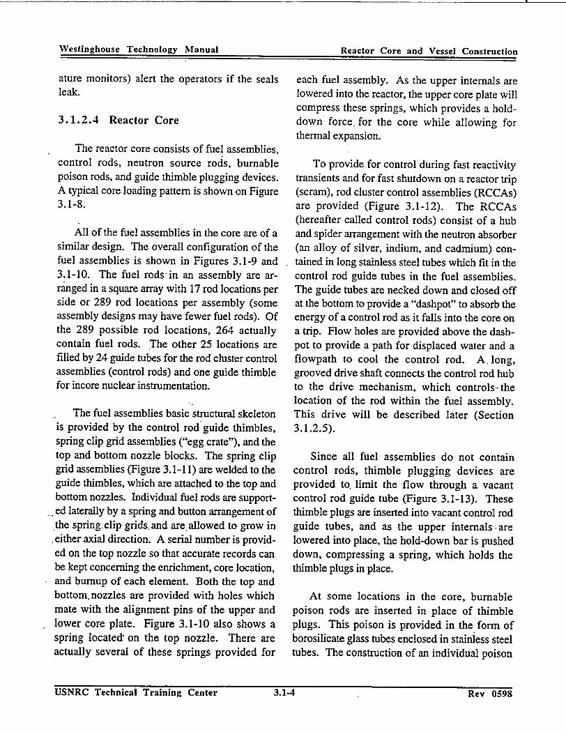
Westinghouse Technology Manual Reactor Core and Vessel Construction
ature monitors) alert the operators if the seals leak.
3.1.2.4 Reactor Core
The reactor core consists of fuel assemblies, control rods, neutron source rods, burnable poison rods, and guide thimble plugging devices. A typical core loading pattern is shown on Figure 3.1-8.
All of the fuel assemblies in the core are of a similar design. The overall configuration of the fuel assemblies is shown in Figures 3.1-9 and 3.1-10. The fuel rods in an assembly are arranged in a square array with 17 rod locations per side or 289 rod locations per assembly (some assembly designs may have fewer fuel rods). Of the 289 possible rod locations, 264 actually contain fuel rods. The other 25 locations are filled by 24 guide tubes for the rod cluster control assemblies (control rods) and one guide thimble for incore nuclear instrumentation.
The fuel assemblies basic structural skeleton is provided by the control rod guide thimbles, spring clip grid assemblies ("egg crate"), and the top and bottom nozzle blocks. The spring clip grid assemblies (Figure 3.1-11) are welded to the guide thimbles, which are attached to the top and bottom nozzles. Individual fuel rods are supported laterally by a spring and button arrangement of the spring, clip grids, and are allowed to grow in either axial direction. A serial number is provided on the top nozzle so that accurate records can be kept concerning the enrichment, core location, and burnup of each element. Both the top and bottom, nozzles are provided with holes which mate with the alignment pins of the upper and lower core plate. Figure 3.1-10 also shows a spring located, on the top nozzle. There are actually several of these springs provided for
each fuel assembly. As the upper internals are lowered into the reactor, the upper core plate will compress these springs, which provides a holddown force' for the core while allowing for thermal expansion.
To provide for control during fast reactivity transients and for fast shutdown on a reactor trip (scram), rod cluster control assemblies (RCCAs) are provided (Figure 3.1-12). The RCCAs (hereafter called control rods) consist of a hub and spider arrangement with the neutron absorber (an alloy of silver, indium, and cadmium) conmined in long stainless steel tubes which fit in the control rod guide tubes in the fuel assemblies. The guide tubes are necked down and closed off at the bottom to provide a "dashpot" to absorb the energy of a control rod as it falls into the core on a trip. Flow holes are provided above the dashpot to provide a path for displaced water and a flowpath to cool the control rod. A long, grooved drive shaft connects the control rod hub to the drive mechanism, which controls-the location of the rod within the fuel assembly. This drive will be described later (Section 3.1.2.5).
Since all fuel assemblies do not contain control rods, thimble plugging devices are provided to limit the flow through a vacant control rod guide tube (Figure 3.1-13). These thimble plugs are inserted into vacant control rod guide tubes, and as the upper internals are lowered into place, the hold-down bar is pushed down, compressing a spring, which holds the thimble plugs in place.
At some locations in the core, burnable poison rods are inserted in place of thimble plugs. This poison is provided in the form of borosilicate glass tubes enclosed in stainless steel tubes. The construction of an individual poison
U�NKC Technical Training Center 3.1-4 Rev 0598Rev 0598
Westinghouse Technology Manual Reactor Core and Vessel Construction
USNRC Technical Training Center 3.1-4

Westinghouse Technology Manual Reactor Core and Vessel Construction
rod and assembly is shown on Figure 3.1-14. These burnable poison rods are provided for additional negative reactivity instead of using soluble poison (boric acid). If boric acid were used, the moderator temperature coefficient could be more positive than allowed by Technical Specifications and accident analysis at high power. Dependent upon its location in the core, a burnable poison assembly may have different numbers of poison rods, with the empty positions filled with thimble plugs.
In order to provide on-scale indication of nuclear instrumentation during startup, neutron sources are provided. These sources are provid-. ed by replacing some of the burnable poison rods with source rods.
The primary source (Figure 3.1-15) may be any of several isotopes, including californium, plutonium-beryllium, polonium-beryllium, and americium-beryllium. This source provides neutrons for indication on the initial startup and for subsequent startups until the secondary source becomes activated.
The secondary source (Figure 3.1-16) is usually antimony-beryllium and is a regenerating source. That is, it is made active by being in the core at power.
3.1.2.5 Control Rod Drive Mechanisms
The control rod drive mechanisms are used to withdraw and insert the control rods and provide sufficient holding power for stationary support. The drive mechanism (Figure 3.1-17) is a magnetic jack device consisting of the latch assembly, the drive shaft assembly, the pressure vessel and rod drive shaft housing, and the operating coil stack.
The latch assembly consists of a -stationary gripper latch and a movable gripper latch. These latches engage the grooved control'rod drive shaft when their respective operating coils are energized. -The latches and drive shaft are inside thepressure housing, which is attached to the reactor vessel head, and are completely covered by reactor coolant. The movable gripper latch has the capability of being :moved 5/8 inch upward when the lift coil is energized.
All of, the operating coils (stationary gripper, ,movable gripper, and lift coils) are- located outside the pressure boundary and have no mechanical connection to the mechanism: When the stationary gripper coil is energized, the stationary gripper latch engages the drive' rod. Upon energizing the movable gripper coil, the movable gripper latch engages the drive shaft. Energizing the lift coil raises the movable gripper latch 5/8 inch.
With proper sequencing of these operating coils (one set for each control rod), a control rod may be raised or lowered. This sequencing is accomplished by an electronic switching control system.
During plant operation, the drive mechanisms normally hold the rods in a static position with only the stationary gripper coil energized. Tripping (scramming) is accomplished by deenergizing all operating coils for all control rods, which disengages the latches and allows the control rods to fall into the core by gravity. Two trip breakers, arranged in series, supply power to the control rod drive system. Opening either trip breaker de-energizes all latch power simultaneously. The trip breakers are operated by the reactor protection system.
USNRC Technical Training Center .KeV tJ�Y�•-3.1-5
Reactor Core and Vessel Constr~uctionWestinghouse 'Technology Manual
..Key 0598USNRC Technical Training Center

Westnghuse echolog MaualReactor Core and Vessel Construc~tion
3.1.3 Summary
The reactor core generates heat to transfer to the steam generators for steam production. The reactor vessel and components support and align the fuel assemblies that make up the reactor core and provide a flowpath to ensure adequate heat removal capability from the fuel assemblies. The structural strength for the fuel assemblies is provided by the control rod guide thimbles, grid straps, and the top and bottom nozzle blocks. The control rod guide thimbles contain either control rods, burnable poison rods, source assemblies, or thimble plug assemblies. Control rods provide control during fast reactivity transients and rapid shutdown capability for a reactor trip.
U�NKC lechnical Training Center 3.1-6 Rev 05983.1-6 Rev 0598
Westinghouse Technology -,Manual
USNRC Technical Training Center

Westinghouse Technology Manual
Section 3.1
Reactor Vessel and Internals
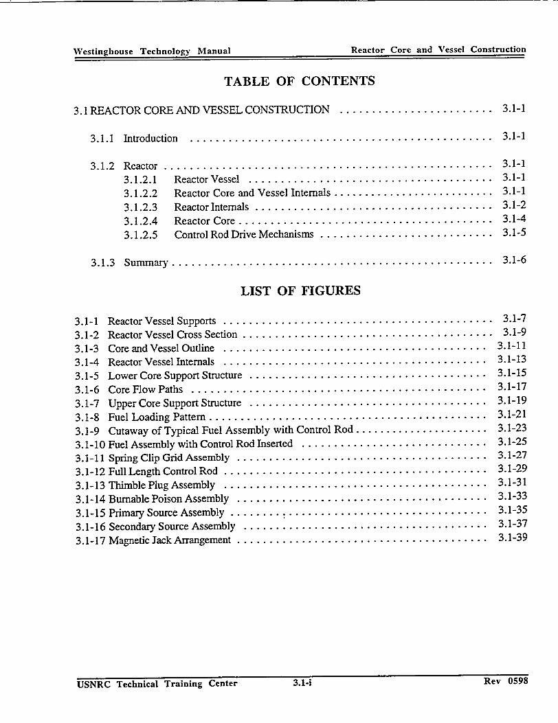
Westinghouse Technology Manual Reactor Core and Vessel Construction
TABLE OF CONTENTS
3.1 REACTOR CORE AND VESSEL CONSTRUCTION ........................ 3.1-1
3.1.1 Introduction .. ............................................... 3.1-1
3.1.2 Reactor ..................................................... 3.1-1
3.1.2.1 Reactor Vessel . ...................................... 3.1-1
3.1.2.2 Reactor Core and Vessel Internals .......................... 3.1-1
3.1.2.3 Reactor Internals ....................................... 3.1-2
3.1.2.4 Reactor Core ......................................... 3.1-4
3.1.2.5 Control Rod Drive Mechanisms ............................ 3.1-5
3.1.3 Summary ................................................... 3.1-6
LIST OF FIGURES
3.1-1 Reactor Vessel Supports . .......................................... 3.1-7
3.1-2 Reactor Vessel Cross Section ........................................ 3.1-9
3.1-3 Core and Vessel Outline . ......................................... 3.1-11
3.1-4 Reactor Vessel Internals . ......................................... 3.1-13
3.1-5 Lower Core Support Structure . ..................................... 3.1-15
3.1-6 Core Flow Paths . .............................................. 3.1-17
3.1-7 Upper Core Support Structure . ..................................... 3.1-19
3.1-8 Fuel Loading Pattern ............................................ 3.1-21
3.1-9 Cutaway of Typical Fuel Assembly with Control Rod ...................... 3.1-23
3.1 - 10 Fuel Assembly with Control Rod Inserted .............................. 3.1-25
3.1-11 Spring Clip Grid Assembly ........................................ 3.1-27
3.1-12 Full Length Control Rod ........................................... 3.1-29
3.1-13 Thimble Plug Assembly . ......................................... 3.1-31
3.1-14 Burnable Poison Assembly . ....................................... 3.1-33
3.1-15 Primary Source Assembly ......... ............................... 3.1-35
3.1-16 Secondary Source Assembly . ...................................... 3.1-37
3.1-17 Magnetic Jack Arrangement ......................................... 3.1-39
USNRC Technical Training Center 3.1-i 1(CV U�Y�Rtev 0.5983.1-iUSNRC Technical Training Center
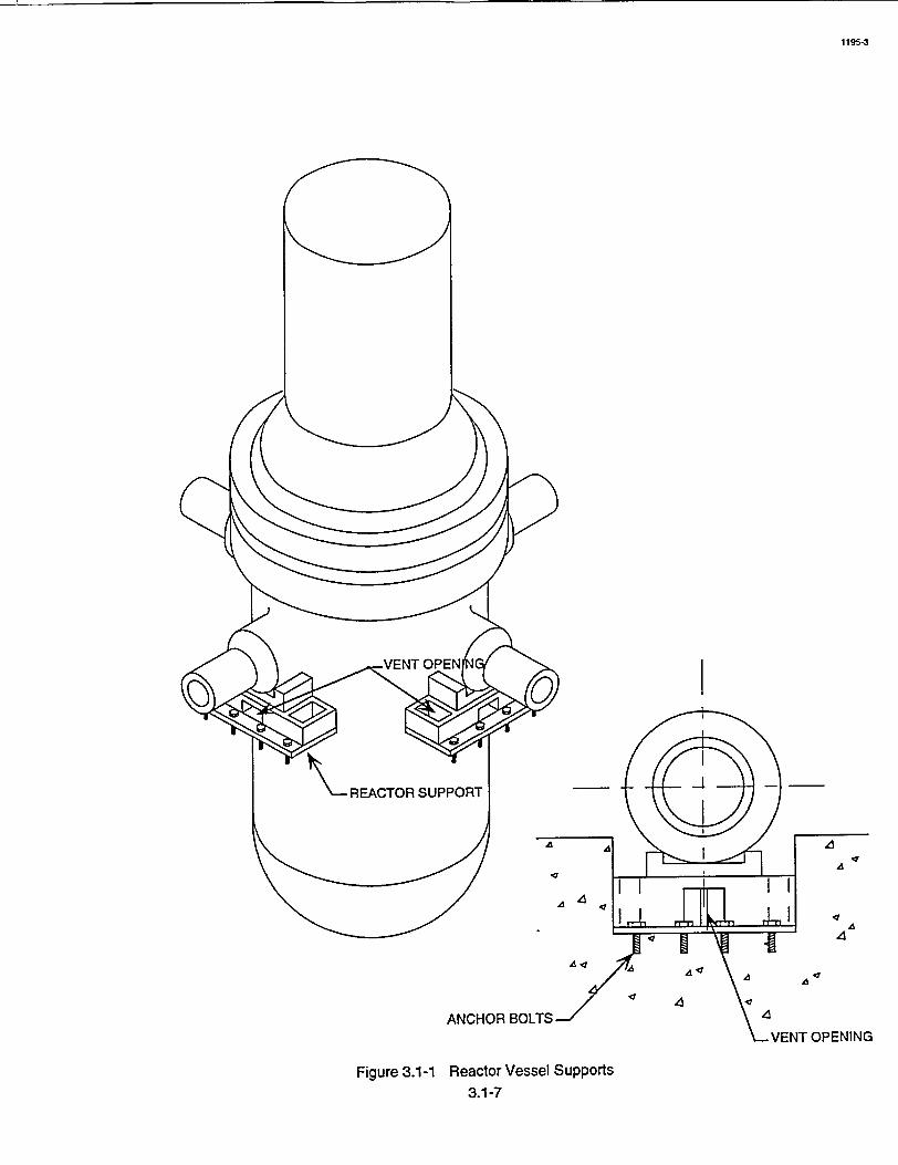
A
ANCHOR BOLTS
Figure 3.1-1 Reactor Vessel Supports
3.1-7
1195-3
A
4
4,
T OPENING
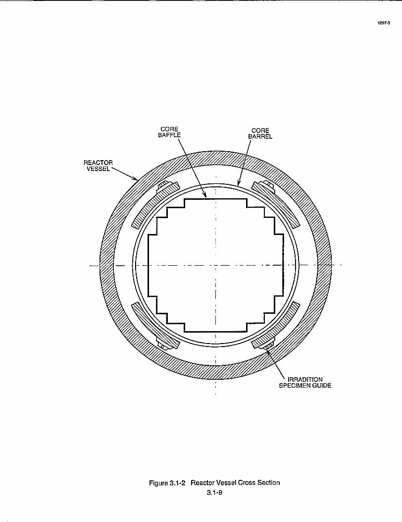
CORE CORE BAFFLE BARREL
Figure 3.1-2 Reactor Vessel Cross Section
" IRRADITION SPECIMEN GUIDE
3.1-9
1297-3
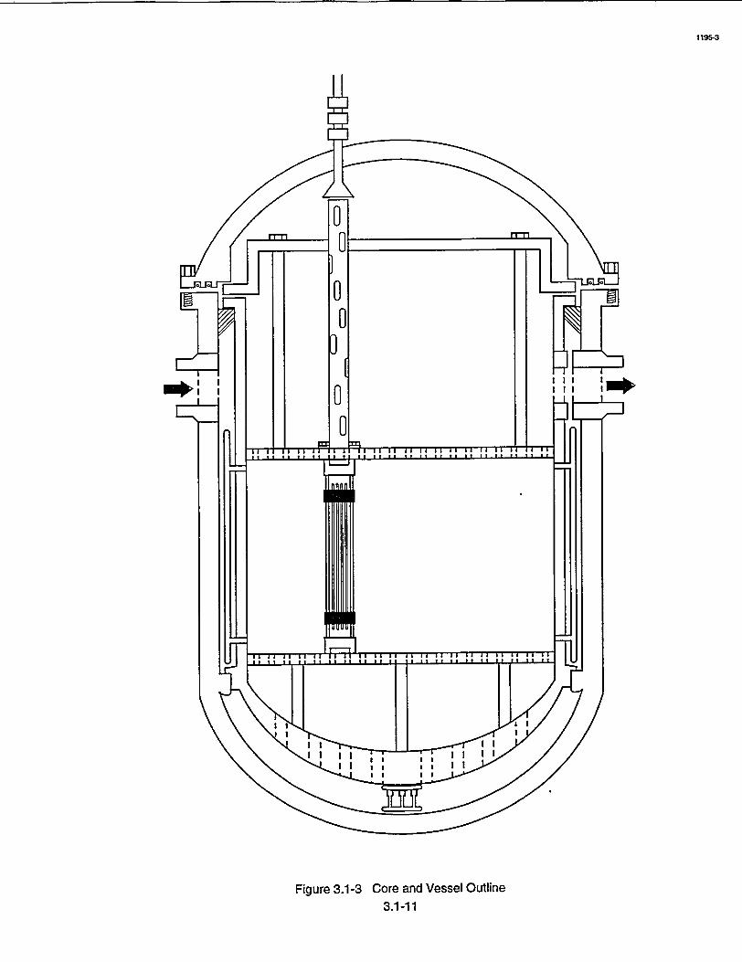
1195-3
Figure 3.1-3 Core and Vessel Outline 3.1-11

CONTROL ROD DRIVE MECHANISM
UPPER SUPPORT PLATE
INTERNALS SUPPORT
LEDGE
CORE BARREL
SUPPORT COLUMN
UPPER CORE PLATE
OUTLET NOZZLE
BAFFLE RADIAL SUPPORT
BAFFLE
CORE SUPPORT COLUMNS
INSTRUMENTATION THIMBLE GUIDES
RADIAL SUPORT
CORE SUPPORT
- ROD TRAVEL HOUSING
- INSTRUMENTATION PORTS
-THERMAL SLEEVE
LIFTING LUG
CLOSURE HEAD ASSEMBLY
HOLD-DOWN SPRING
CONTROL ROD GUIDE TUBE
CONTROL ROD DRIVE SHAFT
INLET NOZZLE
CONTROL ROD CLUSTER (WITHDRAWN)
ACCESS PORT
REACTOR VESSEL
LOWER CORE PLATE
Figure 3.1-4 Reactor Vessel Internals 3.1-13
1195-3
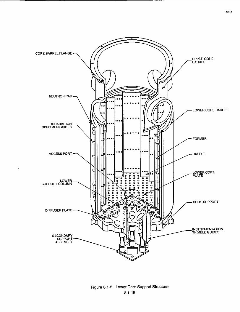
1195-3
CORE BARREL FLANGE.
NEUTRON PAD.
IRRADIATION, SPECIMEN GUIDES
ACCESS PORT
LOWER SUPPORT COLUMN
DIFFUSER PLATE
SECONDARY SUPPORT
ASSEMBLY
LOWER CORE BARREL
Figure 3.1-5 Lower Core Support Structure 3.1-15
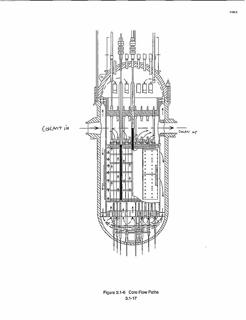
C~L~T IN
Figure 3.1-6 Core Flow Paths 3.1-17
1195-3
CvJCLAn wT

THERMOCOUPLE COLUMN
CONTROL ROD ,-GUIDE TUBE
EXTENSION
UPPER SUPPORT PLATE
SUPPORT COLUMN
UPPER CORE PLATE
Figure 3.1-7 Upper Core Support Structure 3.1-19
1297-32 31
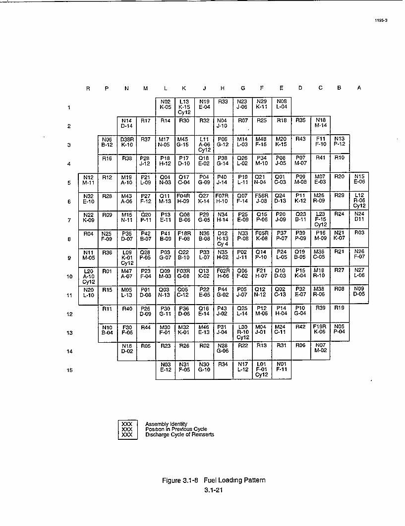
R P N M L K J H G F E D C B A
N02 K-05
L13 K-15 Cy12
R14 R30
P18 H-12
P30 G-1 1
P17 D-10
P36 D-06
N19 E-04
018 E-02
016 E-14
R02
R33
N04 J-10
P38 G-14
P43 J-02
N28 G-06
R25
P12 M-06
M1 M4 Ll70
1 M412
N-05G-1 A-6
G-2 L03K-i5
K-15
t 1R18R07R32
P34 M-10
P14 H-04
R31R22 R13R23 R26
5
6
7
8
9
10
11
12
13
14
15N30
G-10N03 N31 E-12 F-05
L01 F-01 Cy12
P08 J-05
N01 F-11
N23 J-06
026 L-02
025 L-14
N17 L-12
R35 N18 M-14
P07 M-07
PlO G-04
N07 M-02
[xx Assembly Identity lxxxi Position in Previous Cycle xx Discharge Cycle of Reinserts
Figure 3.1-8 Fuel Loading Pattern 3.1-21
R06
1195-3
1
2
3
4R41
N14 D-14
R38
R40
R17
P28 J-1 2
P26 D-09
N06 D38RtR37IM17 M45 I LIi PO6 M14 tM481 M20 RP43 F1l1 N13 B-12 K-1 0 I N-O5 G-15 IA-06 G -12 IL-03 IF-15 IKi F-1O 0 P-12
___ ___ ___ ___ JCy12j _ _1 __1 __ 1pl0R16
P19R111
N10 3 4 M30 M32 M4 31 L30 M4M4R2F9 O !B-0]4 F-06 F-01 K-01 M463 jJ04 R- 0 04ý -6 P0
N12 R12 M19 P21 004 017 P04 P40 P19 021 001 P09 M07 R20 N15 M-11 A-1 L-09 N-03 0-04 G-09 J-14 L-11 N-04 C-03 M-08 E-03 E-06
N32 R28 M43 P27 011 F04R 027 F07R 007 F56R 024 P11 M26 R29 L12 E-10 A-06 F-12 M-13 H-09 K-14 H-10 F-14 J-08 D-13 K-12 R-09 R-06
_____Cyi 2
N22 R09 M15 0120 P13 008 P29 N34 P25 015 P20 023 L23 R24 N24 K-09 N-1i P-1 E-11 B-06 G-05 H-14 E-09 P-06 J-09 B-il F-i5 D11
_____ ____ _____Cyl 2 __
R04 N25 P35 P42 P41 F18R N36 D12 N33 F05R P37 P39 P16 N21 R03 F-09 D-07 B-07 B-09 F-08 B-08 H-13 P-08 K-08 P-07 P-09 M-09 K-07
__________ _Cy 4 ___
Nil R36 L09 028 P03 022 P33 N35 P02 014 P24 019 M36 R21 N26 M-05 K-01 P-05 G-07 B-10 L-07 H-02 J-11 P-10 L-05 B-05 C-05 F-07
___ CyI12 I__ I__
L20 R01 M47 P23 009 F03R 013 F02R Q06 F21 010 P15 M18 R27 N27 A-1 0 A-07 F-04 M-03 G-08 K-02 H-06 F-02 H-07 D-03 K-04 R-10 L-06 Cyl 2 I__ I__ I I I
N20 R15 M05 P01 003 005 P22 P44 P05 012 002 P32M38 08 N09 L-0 L-13 N-13 C-12 E-05 G-02 J-07 N-12 C-13 E-07 R-06 D-05
R34
N16 D-02
R05
R39
N29 K-1 1
N08 L-04

TOP NOZZLE
CONTROL ROD
GRID
BULGE JOINTS
GRID SPRING •
BOTTOM NOZZLE
HOLD DOWN SPRING
_FUEL ROD
>THIMBLE TUBE
MIXING VANES
DASHPOT REGION
DIMPLE
"THIMBLE SCREW
Figure 3.1-9 Cutaway of Typical Fuel Assembly with Control Rod 3.1-23
129743

0.8 75 DIA REF -0.875 DIA REF
- 8.424 SQ 000000 •Bottom Nozzle 7.1 2 8.404 SQ REF 6.750-'
C
REFRE
02
"-n \-0.551 DIA REF "c BOTTOM VIEW TOP VIEW M
v Ad
., 159.8 REF ýZ <--6.2 REF--- -30.6 REF <<-56.8 REF *-83.0REF 4<-109.2REF <<-135.4REF ... ,-154.0REF (_ 2.7 REl Eni
Plenum
0. f
apter Plate
NOTE: ALL DIMENSIONS ARE IN INCHES.
30

1195-3
Figure 3.1-11 Spring Grid Clip Assembly 3.1-27
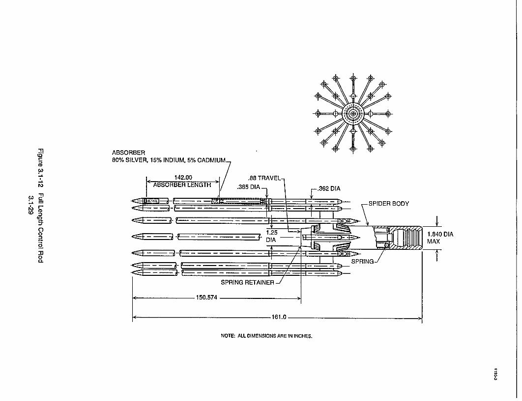
ABSORBER 80% SILVER, 15% INDIUM, 5% CADMIUM.
____ ___ ____ ___ ____ ___ 1.25
DIA
•-t- -•F •-1 t-- -- -
NOTE: ALL DIMENSIONS ARE IN INCHES.
'0
C4
p,
(0
(0 0
".1'
m, I-r
r
(0
CL 0
30
0
DIA
161.0

I _ _C
NOTE ALL DIMENSIONS ARE IN INCHES.
Figure 3.1-13 Thimble Plug Assembly 3.1-31
1195-3
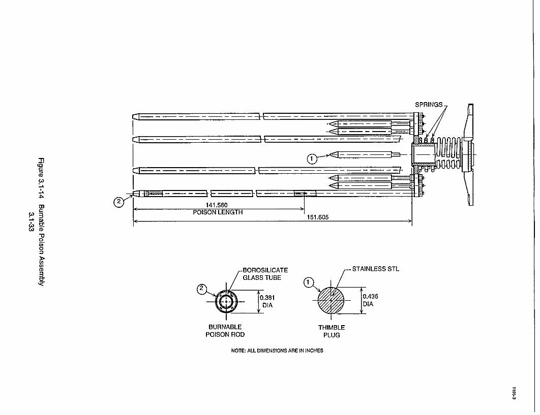
-1 - -
-J -I - - - - -__ - - ~- HE_-_ - - - -__ - -__ - __--
BOROSILICATE STAINLESS STL GLASS TUBE 1
0.381 0.436 +DIA I
BURNABLE THIMBLE
POISON ROD PLUG
NOTE: ALL DIMENSIONS ARE IN INCHES
21
WCD -u
C3
•cr "I<
-u 0
CD 3
cr
WA

kc - - --- - -t-r - - -. . .. --•-I-!4- - - - - --- - - - -. .
-C44,•,F -• - - -I-!!- - - -= --- - .- -.-- -- -- /--
I I 32.5 NOM. I 1.5 NOM. 001
UL:H --CALIF150.4-
NOTE ALL DIMENSIONS ARE IN INCHES
BOROSILICATE GLASS TUBE
1
PRIMARY SCOURCE
(i
-n
Ill
"42 CD
(D
3
c) -l
t
2
(/B
(n (B 2
Fl
CA) En
Ul
< > i
BURNABLE POISON
l
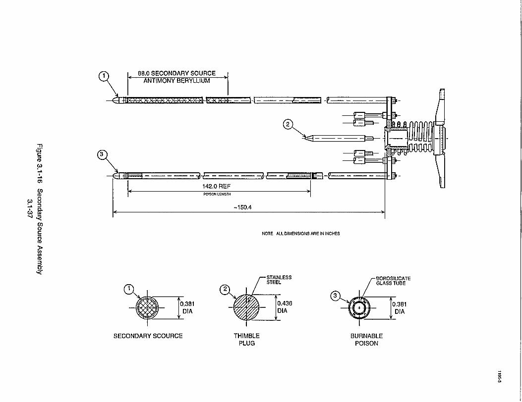
NOTE ALL DIMENSIONS ARE IN INCHES
S10381 DIA
SECONDARY SCOURCE
"BOROSILICATE GLASS TUBE
0.381 DIA
BURNABLE POISON
THIMBLE PLUG
1
-4
2i
CD
-n -"
(D 0 0
:3 w
0
CD
(D
3/ CJ)
142.0 REF
-150.4
CA)
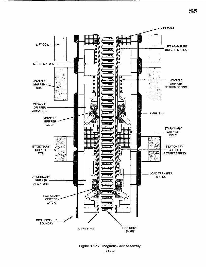
0990-329 8-4 2 2-4
LIFT POLE
LIFT ARMATURE RETURN SPRING
MOVABLE GRIPPER
RETURN SPRING
G
STATIONARY - GRIPPER
POLE
STATIONARY - GRIPPER
RETURN SPRING
RCS PRESSURE BOUNDRY
GUIDE TUBE ROD DRIVE SHAFT
Figure 3.1-17 Magnetic Jack Assembly
3.1-39
Westinghouse Technology Manual
Section 1.3
Instrumentation and Control

Westinsuhouse Technology ManualIntuettoadCnrl
'TABLE OFCONTENTS
1.3 INSTRUMENTATION AND CONTROL ........................... ..1.3-1
1.3.1 Introduction .. ............................................... 1.3-1
1.3.2 Pressure 1.3.2.1 1.3.2.2 1.2.2.3
Sensing Instruments .............................. Bourdon Tube ................................. Bellows Pressure Sensor .......................... Diaphragm Pressure Sensor ........................
..1.3-1
..1.3-1 ..... 1.3-2 ..... 1.3-2
1.3.3 Flow Sensing Instruments ............. 1.3.3.1 Primary Devices ............ 1.3.3.2 Bellows Flow Sensor ......... 1.3.3.3 Diaphragm Flow Sensor ....... 1.3.3.4 Magnetic Flow Sensor ........
1.3.4 Level Sensing Instruments .............................. 1.3-31.3.4.1 Variable Capacitance Differential Pressure Sensor .
1.3.5 Temperature Sensing Instruments ........ 1.3.5.1 Fluid-Filled System .......... 1.3.5.2 Thermocouples ............. 1.3.5.3 Resistance Temperature Detectors .
I 1.3.6 Mechanical to Electrical Signal Conversion .. 1.3.6.1 Force Balance Transmitter ...... 1.3.6.2 Movable Core Transmitter ...... 1.3.6.3 Variable Capacitance Transmitter .
1.3.7 Controllers and Signal Conditioning ...... .......... 1.3.7.1 Bistable Control ...................... 1.3.7.2 Proportional Control ................... 1.3.7.3 Proportional Plus Integral Control ........... 1.3.7.4- Proportional Plus Integral Plus Derivative Control 1.3.7.5 Manual/Auto Control Stations ........... 1.3.7.6 Signal Conditioning ...................
1.3.8 Logic Diagrams..................... 1.3.8.1 "OR"Logic ............... 1.3.8.2 "AND" Logic .............. 1.3.8.3 "NOT" Logic ..............
USNRC Technical Training Center 1.3-i Rev O59�
1.3-2 1.3-2 1.3-2
- 1.3-3 1.3-3
. 1.3-4
.1.3-4 1.3-4 1.3-4
.1.3-5
1.3-5 1.3-5 1.3-5 1.3-6
1.3-6 1.3-6 1.3-7 1.3-7 1.3-8 1.3-9 1.3-9
1.3-10 1.3-11 1.3-11 1.3-11
USNRC Technical Training Center
Instrumentation and Control
1.3-i Rev 0598

Westinghouse Technology Manual Instrumentation and Control
TABLE OF CONTENTS (continued)
1.3.8.4 Retentive Memory ..................
1.3.9 Electncal Relay ............................
S................ 1.3-11
................ 1.3-11
LIST OF TABLES
1.3-1 Gain and Proportional Band ......................
LIST OF FIGURES
1.3-1 1.3-2 1.3-3 1.3-4
.................. 1.3-7
Simple Bourdon Tube ......... Wound Pressure Detectors ...... Sealed Pressure Detectors ...... Primary Devices .............
1.3-5 Bellows Flow Sensor ................... 1.3-6 Diaphragm Flow Sensor ................. 1.3-7 Magnetic Flow Sensor .................. 1.3-8 Direct Level Measurement Devices .......... 1.3-9 Differential Pressure Level Detector .......... 1.3-10 Reference Leg Differential Pressure System .... 1.3-11 Variable Capacitance Differential Pressure Sensor 1.3-12 Fluid-Filled Temperature Sensor ............ 1.3-13 Thermocouple ........................ 1.3-14 Resistance Temperature Detector ............ 1.3-15 Force Balance Transmitters ............... 1.3-16 Movable Core Transmitters ............... 1.3-17 Variable Capacitance Transmitters ........... 1.3-18 Basic Control Diagram .................. 1.3-19 Proportional Controller .................. 1.3-20 Proportional Plus Integral Controller ......... 1.3-21 Time Constant ........................1.3-22 Proportional Plus Integral Plus Derivative Controller ............... 1.3-23 PID Controller Responses ................................. 1.3-24 Manual/Auto Control Stations ............................... 1.3-25 Signal Conditioning Output with Varying Time Constants ............ 1.3-26 Logic Functions ........................................ 1.3-27 Relay ...............................................
1.3-13 1.3-15 1.3-17 1.3-19 1.3-21 1.3-23 1.3-25
. . 1.3-27 1.3-29 1.3-31 1.3-33
• . 1.3-35 .. 1.3-37 •. 1.3-39
1.3-41 1.3-43 1.3-45
•. 1.3-47 1.3-49 1.3-51 1.3-53 1.3-55 1.3-57 1.3-59 1.3-61 1.3-63 1.3-65
USNRC Technical Training Center 1.3-u Rev 0598
I
Westinghouse Technology Manual Instrumentation and Control
.................
.... •............
..... o......o....
........ •........
USNRC Technical Training Center 1.3-ii Rev 0598
Westinghouse Technology Manual Instrumentation and Control
1.3 INSTRUMENTATION AND CONTROL
Learning Objectives:
1. Describe the type of sensing instruments used to sense pressure, temperature, and flow.
2. Explain how the properties in (1.) are con-, verted into electrical outputs.
3. Explain how the following controllers respond to a step change and ramp change in input:
a. Bistable, b.- Proportional, c. Proportional plus integral, and d. Proportional plus integral plus derivative.
4. Explain the input and output relationships of
the standard logic circuits.
in pounds per square inch'(psi) to the vacuum in the main condenser measured in inches of mercury (in.Hg). The devices listed in this section are used for the measurement of system pressure.
1.3.2.1 Bourdon Tube
The simple bourdon tube (Figure 1.3-1) consists of an oval tube rolled into an arc of a circle. One end is open to the process variable to be measured, and the other end is closed. The surface area on the outer portion of the arc is larger than the surface area of the inner portion, and when pressure (force per unit area) is applied, the tube, tends to straighten out very slightly. If the pressure is removed, the elasticity
..of the tube causes it to return to its original shape. The pressure of the fluid is converted to a mechanical imotion by the bourdon tube. -This motion can be converted into-an electrical or pneumatic signal, or can drive a pointer on a local indicating gage for measurement of the applied pressure.
1.3.1 Introduction
This-section -addresses the detection of "process .variables and the conversion of these measured values into electrical or pneumatic "signals. These signals will then be used for indication and control functions. The basic controllers used in power plant control systems will be discussed, including their response to various input signals. In addition, a brief discussion of simple logic circuits will concluide this section.
1.3.2 Pressure Sensing Instruments
Pressure, defined as force per unit area, is one of the measured and controlled properties. Pressure measurements range from the high pressure of the reactor coolant system measured
The spiral element (Figure 1.3-2(a)) is a variation of the simple bourdon tube. It is similar to the bourdon tube excepts that it is wound in the form of a spiral containing four or five turns. The spiral element amplifies the'movenient of the closed end of the bourdon tube.
The helical type of measuring element is a second modification (Figure 1.3-2(b)) of the bourdon element. It is a thin-walled tube that has bleen'flattened 'on opposite sides to produce an approximately elliptical'cross section: The tube is then formed into a spiral. -When pressure is applied to the open end, the tube tends to uncoil.
USNRC Technical Training Center 1.3-1 - Rev U59Z5"-USNRC Technical Training Center
-Westinghouse Technology Manual ,Instrumentation and Control
1.3-1 Rev 0598•S- A--A--.
Westinghouse - Technology Manual Instrumentation and Control
1.3.2.2 Bellows Pressure Sensor
The bellows pressure sensor (Figure 1.33(a)) is made up of a metallic bellows enclosed in a shell, with the shell connected to a pressure source. Pressure acting on the outside of the bellows compresses the bellows and moves its free end against the opposing force of the spring. A rod attached to the bellows transmits this motion to the pressure transmitter.
1.3.2.3 Diaphragm Pressure Sensor
The diaphragm pressure sensor (Figure 1.33(b)) consists of a metallic diaphragm which is rigidly supported at each end,, a spring, and a force bar that is connected to, the diaphragm. When pressure is applied, the diaphragm moves in opposition to the spring, which causes motion of the force bar. When pressure is removed, the elasticity of the diaphragm and action of the spring return the sensor to its zero pressure condition.
1.3.3 Flow Sensing Instruments
Selected pressure detection devices may be used to provide a reliable measurement of process flow. To measure flow in this manner, a
differential pressure (AP) is creited by some type of primary device such as an orifice plate, a flow nozzle, or a flow venturi. Flow rate measured in this manner is proportional to the square root of
the AP. The AP is sensed and converted from a mechanical movement to an electrical signal for flow measurement.
1.3.3.1 Primary Devices
1. Orifice Plate
The orifice plate (Figure 1.3-4(a)), in its most common form, is merely a circular hole'in a thin, flat plate that is clamped between the flanges at a joint in the system piping. The orifice plate is inexpensive and accurate, but has poor pressure recovery.
2. Flow Nozzle
The flow nozzle (Figure 1.3-4(b)) provides better pressure recovery (i.e., less pressure loss) than the orifice plate. It consists of a rounded inlet cone and an outlet nozzle.
3. Flow Venturi
The flow venturi (Figure 1.3-4(c)) has the best pressure recovery characteristics and is used in those systems where a high pressure drop across the primary element is undesirable. The venturi consists of rounded inlet and outlet cones connected by a constricted middle section. As the velocity increases in the constriction, the pressure decreases. A pressure tap is provided in this low pressure area.
1.3.3.2 Bellows Flow Sensor
The bellows flow sensor (Figure 1.3-5) consists of two bellows, one that senses the high pressure (inlet) side of the primary device and another that senses the low pressure (outlet) side of the primary device. The difference in force exerted by the two bellows is proportional to the differential pressure developed by the primary element. A mechanical connection is made to a force bar to convert the differential pressure
USNRC Technical Training Center 1.3-2 Rev 0598Rev 0598
L_
Westinghouse .Technology Manual Instrumentation and Control
USNRC Technical Training Center 1.3-2
Wes~tinahniise Technoloev Manual ntuetioadCnrl
signal to an electrical signal. Mechanical to electrical signal conversion is described in Section 1.4.5. Since the flow rate is proportional
to the square root of the AP, a square root
extractor circuit is required to convert the electri
cal output into flow indication.
1.3.3.3 Diaphragm Flow Sensor
Again, the principle of opposing forces created by the differential pressure across the
primary device is used to sense flow with the
diaphragm flow sensor (Figure 1.3-6). The displacement of the diaphragm causes motion of
a force bar, and the AP signal is converted into
an electrical signal. A square root extractor is
again required. The majority of the flow transmitters in the plant use diaphragm flow sensors.
1.3.3.4 Magnetic Flow Sensor
Unlike the previous flow sensors discussed in this section, the magnetic flow sensor (Figure 1.3-7) does not require a primary element., The
magnetic flow transmitter works on the principle that voltage can be generated if relative motion
exists between a conductor and a magnetic field.
The liquid is -used as the conductor. The flow transmitter generates the magnetic field, and the
,flow of the liquid provides the relative motion. Electrodes located in the piping detect the generated voltage.
1.3.4 Level Sensing Instruments
Most measurements of level are based on a pressure measurement of the liquid's hydrostatic head (Figure 1.3-8). This hydrostatic head is the weight of the liquid above a reference or datum
line. At any point, its force is exerted equally in
all directions and is independent of the volume of liquid involved or the shape of the vessel. The
measurement of pressure as a result of level head can be translated to level height above the datum line as follows:
H =P/D
where: H = height of liquid, P = pressure resulting from hydrostatic
head, and D = density of liquid.
The relationship of the height of -water above the gauge to the pressure is irue if neither the
atmospheric pressure above the water nor the water density (teiriperature) changes.- A change
in either of these'parameters would necessitate a calibration change.
Both bellows and diaphragm pressure sensors are used to sense level. On tanks that are vented, the low side of the differential pressure sensor is open to atmospheric pressure. Pressurized tanks (Figure 1.3-9) have reference legs that
tap into the gas space of the tank. Therefore, the level indication is not affected by changes in tank
,pressure. The pressure at the top of the tank is applied to the low pressure side of a differential pressure, transmitter . The high pressure is
subjected to both the vapor pressure on top of the liquid and the hydrostatic head of the liquid itself. The differential pressure transmitters output is the pressure difference between the high pressure
-,(hydrostatic-+ vapor pressure) and the low •,pressure (vaporpressure only) connections.
The pressurizer and steam generators use a filled.(wet) reference leg (Figure 1.3-10). The low pressure side of the differential pressure transmitter is now the tank connection (variable leg) while the high pressure side is the reference
leg side. Level (AP) is sensed in accordance
TJSNRC Technical Training Center 1.3-3 �ev U�Y�1.3-3"*USNRC Technical Training Center
Instrumentation and Control
Rev 0u595
Westnghuse echolog MaualInstrumentation and Control
with the following equation:
AP = HrDr - HvDv
where: Hr = height of the reference leg, Dr = density of the reference leg, Hv = height of the variable leg, and Dv = density of the variable leg.
The reference legs are kept full by condensate pots that tap into the steam space of both vessels. Two points should be noted from the above formula. First, a densityý change in either the
reference or variable leg will affect the AP that is seen by the sensor. Second, when the vessel is full, the AP is equal to zero. Both flow and level sensors are referred to as differential pressure cells or transmitters. The P is sensed and converted from a mechanical movement to an electrical signal for flow or level measurement.
1.3.4.1 Variable Capacitance Differential Pressure Sensor
A variable capacitance differential pressure sensor is one type of instrument used to measure the differential pressure caused by level or flow (Figure 1.3-11). Two isolating diaphragms (one diaphragm for the high pressure input and one diaphragm for the low pressure input) are used. The diffeiential pressure exerts a force through the'silicon fill oil to- change the'position of the sensing diaphragm. The change in sensing diaphragm position is detected by the capacitor plates.^ The change in capacitance is electionically converted to a 4 to 20 milliamp output.
1.3.5 Temperature Sensing Instruments
Temperature is one of the most measured and controlled variables in the nuclear plant. Uses of temperature measurements range from inputs into the reactor protection system to measurement and control of the chilled water temperature from the station air conditioning system. The three basic types of temperature detectors used are the fluidfilled system, the thermocouple, and the resistance temperature detector. Each of these temperature detectors is discussed in the following sections.
1.3.5.1 Fluid-Filled System
Fluid-filled temperature detectors are usually gas-filled "pressure" detectors (Figure 1.3-12). When the temperature of a gas changes, its pressure also changes. The pressure change of the gas is sensed by a bourdon tube type pressure sensor, in which the bourdon tube is connected to a pointer that travels across a scale calibrated in temperature units. The primary use of these systems is local temperature indication.
1.3.5.2 Thermocouples
When two dissimilar metals are welded together and this junction is heated, a voltage is developed at the free ends. The magnitude of the voltage is proportional to the temperature difference between the hot and cold junctions (Figure 1.3-13). and a function of the materials used in thermocouple cofistruction. Because connections must be made to the thermocouple at the cold junction and at the -measuring device, all thermoelectric systems consist of three separate thermocouples:- the thermocouple proper,' the external lead wire, and the reference junction. The voltage-devel'ped in the circuit is then a combination of the voltages generated by all three
U�NKC technical Training Center 1.3.4 Rev 0598Rev 0598
- I
Westinghouse Technology Manual
USNRC; Technical Training Center 1.3-4
Westinghouse Technoloirv ManualIntueaioadCnrl
junctions. If the temperature at the reference junction changes, the total voltage of the circuit changes, and the proportionality between the process temperature and measured voltage is destroyed. The temperature of the reference junction must be kept constant, or changes in this temperature may be compensated for by a temperature sensitive resistor. The temperature sensitive resistor will provide a voltage drop in the circuit to compensate for reference junction temperature changes. The incore system uses
ýthermocouples as temperature sensors.
1.3.5.3 Resistance Temperature Detectors
In Figure 1.3-14, a typical bridge circuit is shown. The bridge consists of three known. resistances'and the resistance temperature detector -(RTD). The RTD's resistance varies with temperature: as temperature increases, the resis-, tance of the RTD also increases. As the resistance of the RTD changes, the voltage difference
o between points "A" and "B" of the bridge circuit changes., This voltage difference is proportional to the temperature that is sensed by the RTD and is used as an input to the indication and control circuits. The RCS hot leg and cold leg temperature detectors are RTDs.
1.3.6 Mechanical to Electrical, Signal, Conversion
In the pressure, flow, and level sensors described above, the'application of pressure results in a mechanical signal. Two devices are available for the conversion of this mechanical "signal into an electrical signal that can be used in the plant control or protection systems. The use of one device,' the force balance transmitter, results in a current output. The use of the other device, the movable core transformer transmitter,
results in a voltage output.
1.3.6.1 Force Balance Transmitter
Force balance refers to the system whereby the free motion of the sensors is limits and actively opposed by some mechanical or electrical means. In Figure 1.3-15, a simplified force balance transmitter is shown. As pressure increases, the diaphragm is moved to the left. This motion, in turn, causes movement of the force bar (the force bar is pivoted at the sealed flexure). The force bar motion causes movement of the reference arm, which closes the gap between the error detector transformer coils and the ferrite disk attached to the reference arm. When the gap of the error detector becomes smaller, the coupling between the transformer coils increases, increasing the output of the error
Sdetector transformer. The output of the error detector is amplified and applied to the force feedback coil. The increased current in the force feedback coil exerts a greater pull on its armature moving the reference arm in the opposite direction, thus restoring the system balance. The mount of current required to maintain the system in balance is proportional- to pressure and, ,therefore, can be used in the indicating and control loops. -Two current ranges, 4 to 20 milliamp or 10 to 50 milliamp, are generally used for this transmitter's output circuitry.,
1.3.6.2 Movable Core Transmitter
In the movable core transmitter (Figure 1.316), the pressure sensor's mechanical linkage is connected to the core of a linear variable differential transformer (LVDT). The LVDT consists of a primary coil and two secondary coils. The movement of the core changes the magnetic flux coupling between the primary coil and the secondary coils which, in turn, causes a change in
USNRC Technical Training Center 1.3-5 Key U�Y6IUSNRC Technical Training Center ,1.3-5
Instrumentation and ControlS.......
Et ...... .......... • .........
Rtev 0.598
Westinghouse Technology Manual Instrumentation and Control
the voltage output of the secondary coils. The secondary coils are connected in series opposition so that the two voltages in the secondary circuit have opposite phases. With the core in the center position of the transformer, the voltage output is zero. This will give a normal voltage range of-10 to 0 to +10 volts.
1.3.6.3 Variable Capacitance Transmitter
A transmitter similar in construction to the variable capacitance differential pressure sensor (Section 1.3.4.1) gives an electrical output directly. The variable capacitance transmitter (Figure 1.3-17) consists of a set of parallel capacitor plates with a sensing diaphragm placed between the plates. The sensing diaphragm and one capacitor plate form one capacitor. The sensing diaphragm and the other capacitor plate from a second capacitor. The capacitors are filled with silicon oil. The need for a pressure-sensing element, such as a bellows or bourdon tube, and its mechanical linkage has been eliminated by connected the process fluid to a separate isolating diaphragm. One side of the isolation diaphragm is in contact with the process stream, while the other side is in contact with the silicon fill oil. When pressure is applied to the isolating diaphragm, force is transmitted through the silicon oil to the sensing diaphragm, causing it to deflect. The deflection of the sensing diaphragm changes the capacitance of each capacitor formed by the sensing diaphragm/capacitor plate arrangement. The change in capacitances, because of sensing diaphragm deflection, is converted to a 4 to 20 milliamp output that is transmitted to the plant protection and/or control systems.
1.3.7 Controllers and Signal Conditioning
In the operation of a nuclear power plant, the majority of electrical and mechanical systems are automatically controlled to maintain certain parameters within their prescribed limits. This can be accomplished by measuring the parameter to be controlled and making adjustments in the associated control system. During steady state conditions, this is relatively simple. However, when plant conditions are changing, the process is more difficult.
The difficulty arises due to dynamic affects such as:
"• time delays for measurement instruments, "* transit time for the parameter to reach the
measuring instrument (i.e., piping lags), and
"* the rate of change of parameters.
Because of these delays, it is important to be able to correct for them electrically and to anticipate parameters that are undergoing a change of state. Controllers provide outputs that are based on the input they receive. They may also respond to rates of change or to the time of deviation from a desired setpoint. The following sections discuss the various types of signal conditioning networks used in process protection and control systems and provides examples of each.
1.3.7.1 Bistable Control
A controller is a device that generates an output based on the input it receives. The input signal is actually an error signal, which is the difference between the measured variable and the desired value, or setpoint (Figure 1.3-18).
USNRC Technical Training Center 1.3-6 Rev 0598
I-
USNRC Technical Training Center 1.3-6 Rey 0598
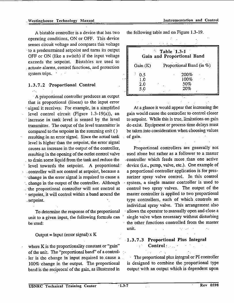
Westinghouse Technology Manual Instrumentation and Control
A bistable controller is a device that has two operating conditions, ON or OFF. This device senses circuit voltage and compares this voltage to a predetermined setpoint and turns its output OFF or ON (like a switch) if the input voltage exceeds the setpoint. Bistables are used to actuate alarms, control functions, and protection system trips.
1.3.7.2 -Proportional Control
A proportional controller produces an output that is proportional (linear) to the input error signal it receives. For example, in a simplified level control circuit (Figure 1.3-19(a)), an increase in tank level is sensed by the level transmitter. The output of the level transmitter is compared to the setpoint in the summing unit ( ) resulting in an error signal. Since the actual tank level is higher than the setpoint, the error signal causes an increase in the output of the controller, resulting in the opening of the outlet control valve
- to drain some liquid from the tank and reduce the level towards the setpoint. A proportional: controller will not control at setpoint, because a 'change in the error signal is required to cause a change in the output of the controller. Although
-,the proportional controller -will not control at - setpoint, it will control within a band around the
setpoint.
To determine the response of the proportional unit to a given input, the following formula can be used:
Output = Input (error signal) x K
where K is the proportionality constant or "gain"
of the unit. The "proportional band" of a controller is the change in input required tocause a 100% change in the output. The proportional band is the reciprocal of the gain, as illustrated in
the following table and on Figure 1.3-19.
Table 1.3-1 Gain and Proportional Band
Gain (K) Proportional Band (in %)
0.5 200% 1.0 100% 2.0 50% 5.0 20%
At a glance it would appear that increasing the gain would cause the controller to control closer to setpoint. While this is true, limitations on gain do exist. Equipment or process time delays must be taken into consideration when choosing values of gain.
Proportional controllers are generally not used alone but rather as a follower to a master
.controller which feeds more than one active
device (i.e., pump, valve, etc.). One example of a proportional controller application is for pressurizer spray valve control. In this control
system, a single master controller is used to control two spray valves. The output of the master controller is applied to two proportional type controllers, each of which. controls an individual spray valve. This arrangement also allows the operator to manually open and close a single valve when necessary without disturbing the other functions controlled from the master unit.
1.3.7.3 Proportional Plus Integral Control
The proportional plus integral or PI controller is designed to combine the :proportional type output with an output which is dependent upon
USNRC Technical Training Center i.i-7 1�ev u�yo
Instrumentation and ControlWestinghouse Technology Manual
Rev 0598USNRC Technical Training Center -1.3-7

Westinghouse Technology Manual Instrumentation and Control
the time the input is away from the setpoint. The integral action eliminates the offset from setpoint that results from the use of, a proportional controller alone. The PI controller function is accomplished by the summation of a proportional unit and an integral unit (Figure 1.3-20).
Prior to examining the operation of the integral action, two terms need to be defined. The first term is "reset rate" and is'defined as the number of times the magnitude of the change in controller output caused by the proportional band deviation will be added to the controller output per unit time. Reset rate is expressed in repeats per minute (RPM). The other term is "reset time" and is defined as the time required to repeat the magnitude of the changed caused by the proportional band action. Reset rate and reset time are reciprocal terms. To illustrate this, assume a controller has a proportional band of 200% (gain = 0.5) and a reset, rate of 2 RPM. If a step change of 20% occurs in the process variable, the magnitude of the change in the controller output due to the proportional band action is 10%. A reset rate of 2 RPM will cause a change of an additional 20% every minfite the error exists. A reset rate of 2 RPM corresponds to a reset time of 0.5 minutes. Therefore, the output of the controller will be changed an additional 10% every 30 seconds.
The addition of integral action to the controller will achieve the desired result of having the control system control at. setpoint, because controller output will continue to change as long as an offset between the actual value of the parameter and its setpoint exists. As the value of the controller changes, the controlled device will be modulated. This action will restore the parameter to setpoint.. The response of the PI controller to step and ramp functions is graphically displayed on Figure 1.3-23.
The steam generator water level control system uses a PI controller for positioning the main feed regulating valves. This allows small errors in level or flow to be compensated for by the integral action of the controller.
1.3.7.4 Proportional Plus Integral Plus Derivative Control
The installation of a derivative action into the control scheme gives the system the ability to start action based upon the rate of change of the control system's input. The proportional integral derivative (PID) controller gives a higher output for rapid rates of change in the input. This is sometimes referred to as an anticipatory circuit.
Once a step input occurs, the rate of change of deviation from setpoint is zero, and the output of the derivative portion of the circuit decays to zero (Figure 1.3-21). The time required for the output to decay by 63.2% of the signal due to the action of the derivative portion of the controller is called the "time constant." The output of the controller is an exponential function and will change by 63.2% of the controllers maximum value in one time constant. For a step input, the output of the derivative portion of the controller will equal zero after 5 time constants. For a ramp input, when the deviation between setpoint and the process parameter is increasing, the portion of the controller output due to derivative action will reach its steady state value in five time constants.
The PID controller is the most sophisticated controller used in the power plant and can be used to summarize the previous types of controllers (Figures 1.3-22 and 1.3-23). The proportional component of the PID provides an output that is proportional to its input. The input signal
to the controller is the error (7) that results from
USNRC Technical Training Center 1.3-8 Rev 0598
I-
Westinghouse Technology Manual Instrumentation. and Control
USNRC Technical Training Center 1.3-8 Rev 0598
Westinrihouse .Technolo2v Manual Instrumentation arid Control
the comparison of the actual value of the parame-, ter and its desired value (setpoint).
Since a change in the input is required to
cause a repositioning of the controlled device, an
inherent offset would exist. The addition of the integral portion of the PID controller eliminates
the offset of the proportional action. The integral portion of the -controller accomplishes this function by adding the integral of the proportional deviation to the output of the controller. This
increase in controller output changes the status of the controlled device and causes the process parameter to achieve the desired value.
Finally, the derivative action adds an anticipatory -feature to the controller. This anticipatory feature is performed by adding a signal to the controller output that is proportional to the rate of change (the derivative) of the proportional band 'deviation. PID controllers are widely used in automatic control systems for rapid response to
key plant parameters. One such application is the pressurizer pressure master controller, which provides an input to proportional controllers for
-the -spray valves,, as discussed in Section
1.3.6.2. The master controller also provides an input to various other pressurizer pressure control functions (heaters, relief valves, etc.).
This allows the controls to anticipate and minimize transient effects on pressure.
1.3.7.5 Manual/Auto Control Stations
There are many models of manual/auto (M/A) control stations for the controllers, discussed
previously., :Each can be used for P, PI, or PID
controllexs and will vary in features according to the desired function., A few.of the M/A stations are shown in Figure 1.3-24.
The M/A station in Figure 1.3-24(A) is a HAGAN unit, which gives an indication of the output signal in percent from 0 to 100%. There are pushbuttons to select AUTO or MANUAL
-control, and ,when in MANUAL-,-the -raise or
lower output buttons gives the operator the capability of directly varying the output signal.
Controllers (B) and (C) have the same features as (A), but a potentiometer is included for varying
the desired setpoint and the -actual measured parameter. MANUAL and AUTO pushbuttons determine the mode of operation, and when in
MANUAL, the slide control on the bottom varies the controller output.
1.3.7.6 Signal Conditioning
There are conditions for which it is desirable to electrically modify an input signal before it
reaches the controller., Three of these conditions will be discussed in this section.
1. Filter or Lag Unit
A filter or lag unit is used to reduce circuit noise affects such as pulses or spikes of very short duration. The filter unit delays (lags) the signal and provides a gradual change in
output so the noise spikes are gone before the output has time to increase and, therefore, little or no response is seen.,
The filter is a simple circuit consisting of a
resistive/capacitive series combination. The time for the capacitor to fully charge will be dependent upon the values of resistance and capacitance. If the time constant is reduced, the time for the capacitor to become fully charged is reduced, and the lag time is short. By increasing the time constant, the charge time is increased; and a longer lag time or delay.:results. Figure 1.3-25,,shows the
R�ev IJ�Yo-,USNRC Technical Training Center 1.3-9
,Instrumentation and Control• Westinphouse .Technology Manual
R- ev 0578
WestinghouseI Teholg M ul nstrumentatin, a A -
response of the lag unit to step and ramp inputs with varying time constants.
In the steam generator water level control system, a lag unit is used to delay the level input signal to the controller. This is necessary since the affects of shrink, and swell would cause the control system to react just the opposite to what is required to restore level to the programmed setpoint.
2. Rate/Lag Unit
Rate/lag units are designed to give an output for a rate of change of the input. This enables the control systems to iespond quicker to changes in the controlled parameter thereby compensating for the delays caused by piping and measurement systems. The unit incorporates both a rate of change circuit and a lag circuit. The lag circuit provides compensation for the noise generated in producing the rate signal. Figure 1.3-25 shows the response of the rate/lag unit to step and ramp inputs for varying time constants:
A rate/lag unit is used in the rod control system for a comparison between nuclear power and turbine power. If the magnitude of the difference between the two is changing, then the response of the controller is to increase or decrease the stepping rate of the rods to anticipate a temperature mismatch and return Tavg to the desired Tref.
3. Lead/Lag Units
Lead/lag units are, used to compensate for dynamic delays. For a step input, these units provide an output greater than the input for a rapid response and then decay to the input value. The output response can be varied by
changing the time constants of the lead and lag functions. The ratio of the lead to lag time constant determines the magnitude of the output pulse, and the lag constant will determine the decay rate. Figure 1.3-25 gives examples of varying time constants for both step and ramp inputs.
Lead/lag circuits are in many protection and control circuits for compensation of dynamic delays. A lead/lag unit may be used in pressurizer pressure control circuit for operation of a power operated relief valve (PORV). The PORV is set to open approximately 100 psi below the high pressure reactor trip setpoint. If a rapid transient is in progress,' the delays may cause the valve opening to be too late to prevent a reactor trip on high pressure. By anticipating the high pressure condition and opening the PORV sooner, a reactor trip may be .avoided. Another use of a lead/lag circuit is in the Tavg input to the rod control system. The Tavg sign'al is sent via a lead/lag network to initiate rod movement earlier due to a deviation between Tayg and Tref. In this- way, the control system can maintain Tavg within prescribed limits without getting large deviations on transients.
1.3.8 Logic Diagrams
The concept of lo'gic diagrams was introduced to provide system information to personnel in an easily interpreted format. Through the use of standard symbols, logic diagrams explain system or component control, and protection and operational capabilities without requiring detailed research of 'complex electrical or mechanical system diagrams. With the use of a few standard symbols and a basic knowledge of the system functions, a large quantity of useful information
u�riz�i.�. iecnnicai iraining Lenter 1.3-lU Rev 0598Rev 0598
Westinghouse Technology ManualK
US1RCL Iechnncal Irainlng t,ýenter 1.3-10
Westinghouse Technology Manual Instrumentation and Control
may be obtained. To illustrate the concept of logic diagrams and their component parts, the basic symbols will be briefly discussed.
The symbols to be discussed will not be all inclusive. However, those discussed are the most common. In every case of logic diagram usage by a vendor, architect, engineer, or utility, an explanation sheet of symbols is included.
1.3.8.1 "OR" Logic
The "OR" logic is represented in Figure 1.326(a). This logic symbolizes an input and an output function. In the "OR" logic flow, any input signal is considered to be passed through to produce an output. The loss of all inputs will cause a loss of the output.
1.3.8.2 "AND" Logic
The "AND" logic is represented in Figure 1.3-26(b). Multiple input functions are required to produce an output function. In the "AND" logic, all input functions or a specified number of the input functions must be present to produce an output.
1.3.8.3 "NOT" Logic
The "NOT" logic represented in Figure 1.326(c) illustrates a function that will produce an output with no input signal. Likewise, with an input signal present, no output is produced.
1.3.8.4 Retentive Memory
This logic function in Figure 1.3-26(d) will either produce an output or not produce an output depending on its last energized input. If the last input signal received is the input aligned with the output, an output signal is allowed to pass. If the
last input signal received is not aligned with the output, the output signal will be terminated.
1.3.9 Electrical Relay
Figure 1.3-27 illustrates the physical layout of a relay and the electrical circuit representations. There are two types of auxiliary contacts used in relays. The "A" contacts are shut when the main relay contacts are shut, and open when the main relay contacts are open. The "B" contacts are open when the main relays contacts are shut, and shut when the main relay contacts are open. These "A" and "B" contacts are used as part of the instrumentation and control circuits for the system controlled by the relay.
USNRC Technical Training Center 1.3-11 Rev O59�1.3-11
Westinghouse Technology Manual Instrumentation and Control
Rev 0598$USNRC Technical Training Center

0191-23 13-1
Figure 1.3-1 Simple Bourdon Tube
1.3-13

0191-23 1 3-2
PRESSURE CONNECTION
POINTER
(a) Spiral pressure detector
POINTER
PRESSURE CONNECTION
(b) Helical pressure detector
Figure 1.3-2 Wound Pressure Detectors
1.3-15
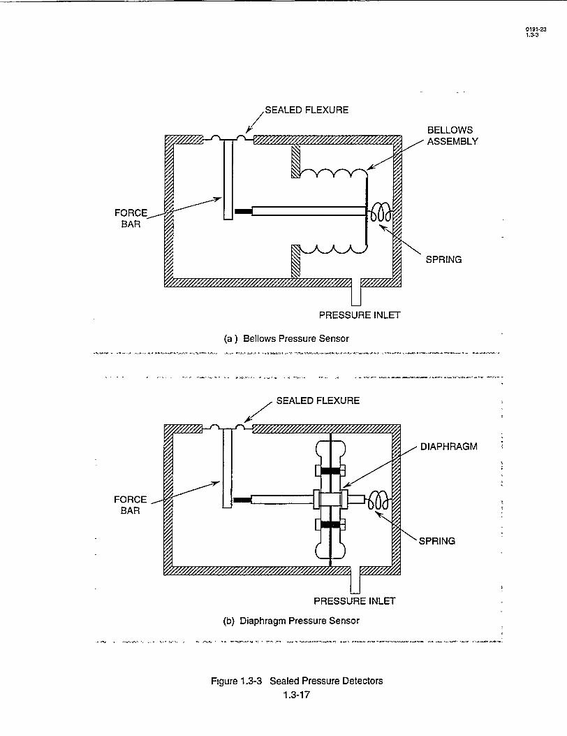
SEALED FLEXURE
BELLOWS
BELLOWS ASSEMBLY
SPRING
PRESSURE INLET
(a) Bellows Pressure Sensor
SEALED FLEXURE
DIAPHRAGM
FORCE BAR
S3 •SPRING
PRESSURE INLET
(b) Diaphragm Pressure Sensor
Figure 1.3-3 Sealed Pressure Detectors
1.3-17
0191-23 1.3-3
FORCE BAR
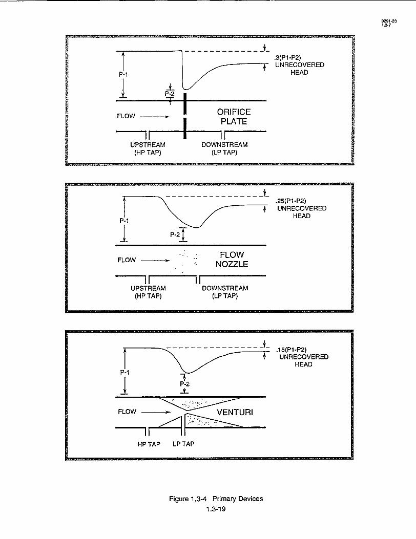
.25(P1-P2) UNRECOVERED
HEAD
FLOW-. FLOW FLOW , "
NOZZLE
II m IUPSTREAM
(HP TAP)DOWNSTREAM
(LP TAP)
Figure 1.3-4 Primary Devices
1.3-19
0291-23 1.3-7
- - .15(P1-P2) + UNRECOVERED
HEAD
P-1T
P-2
FLOW VENTURI
HP TAP LP TAP
P-21
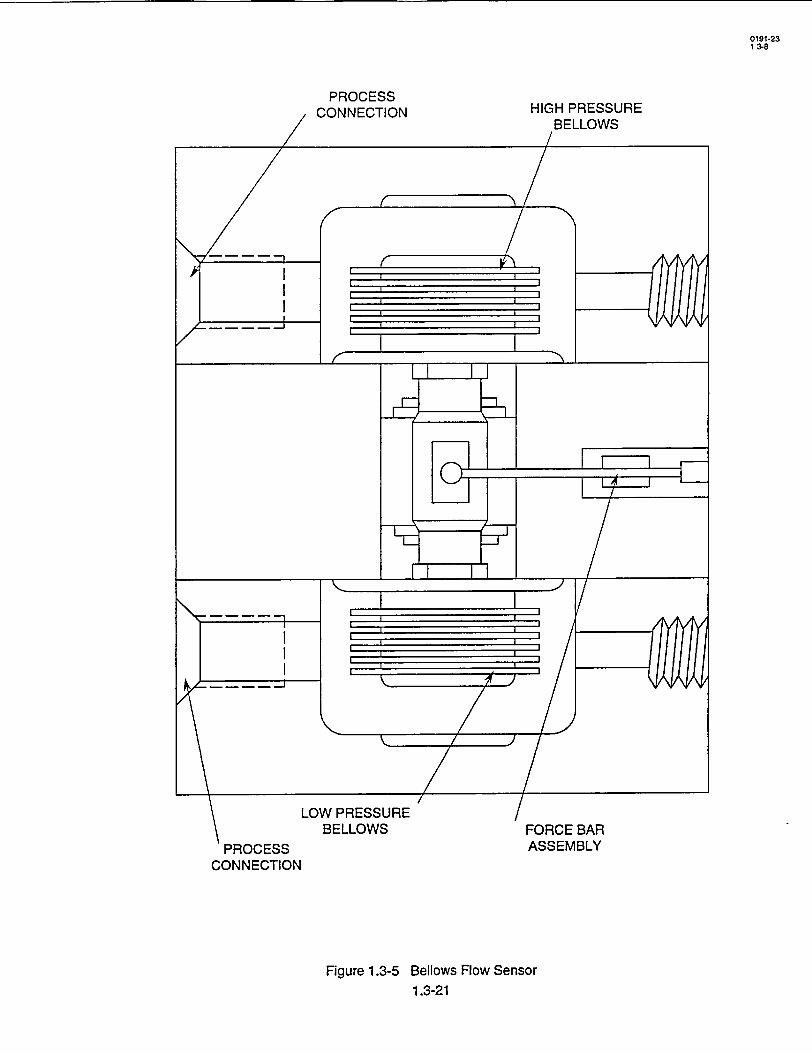
C
PROCESS CONNECTION
0191-23 1 3-8
PROCESS .ONNECTION HIGH PRESSURE
BELLOWS
N PRESSURE BELLOWS FORCE BAR
ASSEMBLY
Figure 1.3-5 Bellows Flow Sensor 1.3-21
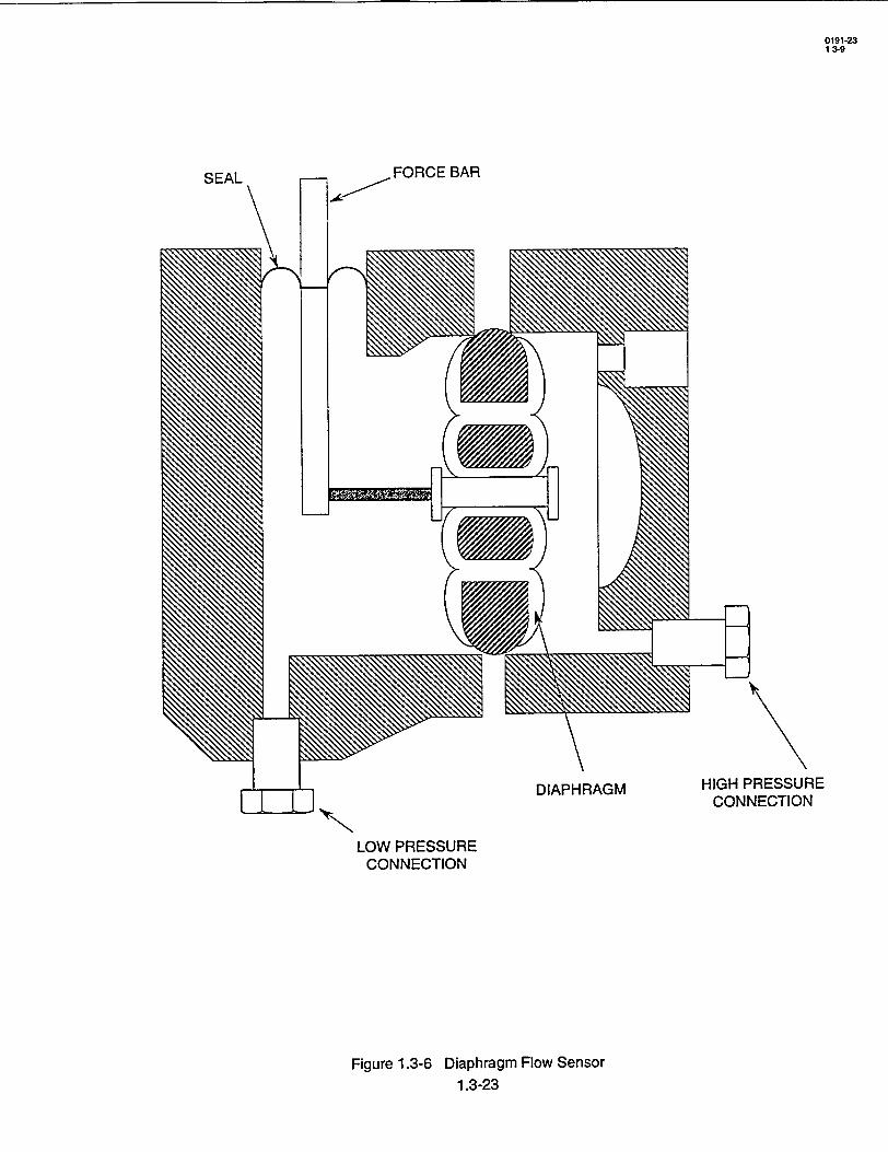
FORCE BAR
HIGH PRESSURE CONNECTION
LOW PRESSURE CONNECTION
Figure 1.3-6 Diaphragm Flow Sensor 1.3-23
SEAL
0191o23 1 39
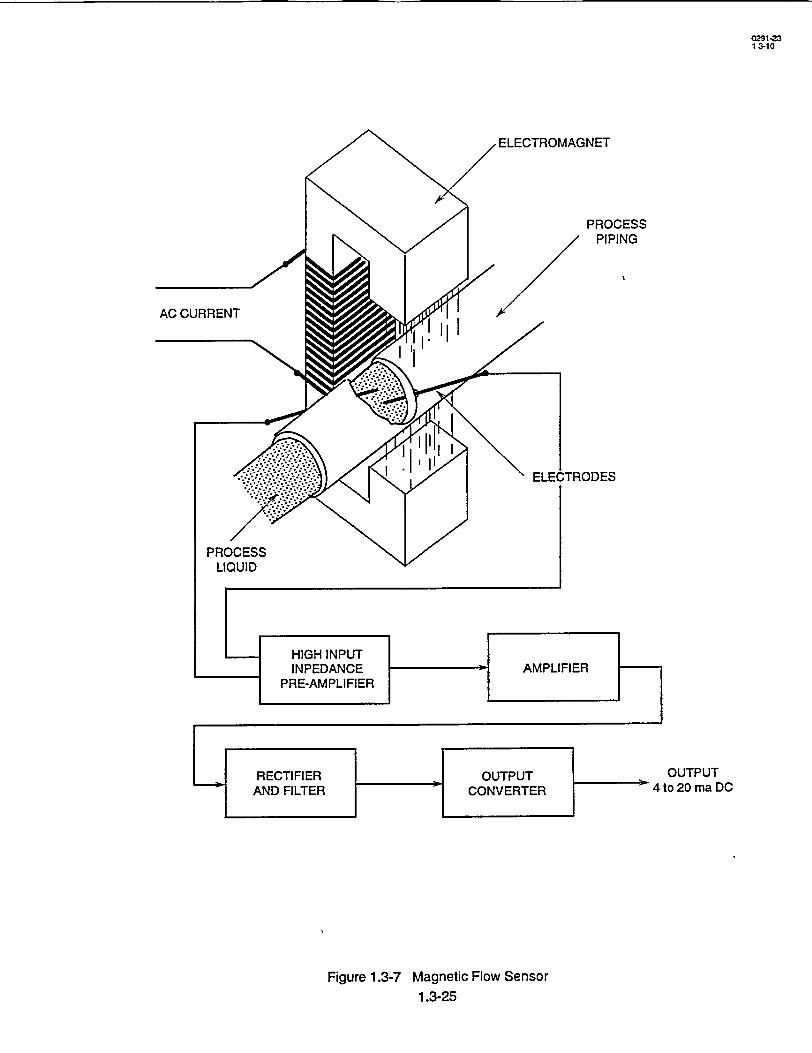
0291-23 1 3-10
OUTPUT 4 to 20 ma DC
Figure 1.3-7 Magnetic Flow Sensor 1.3-25
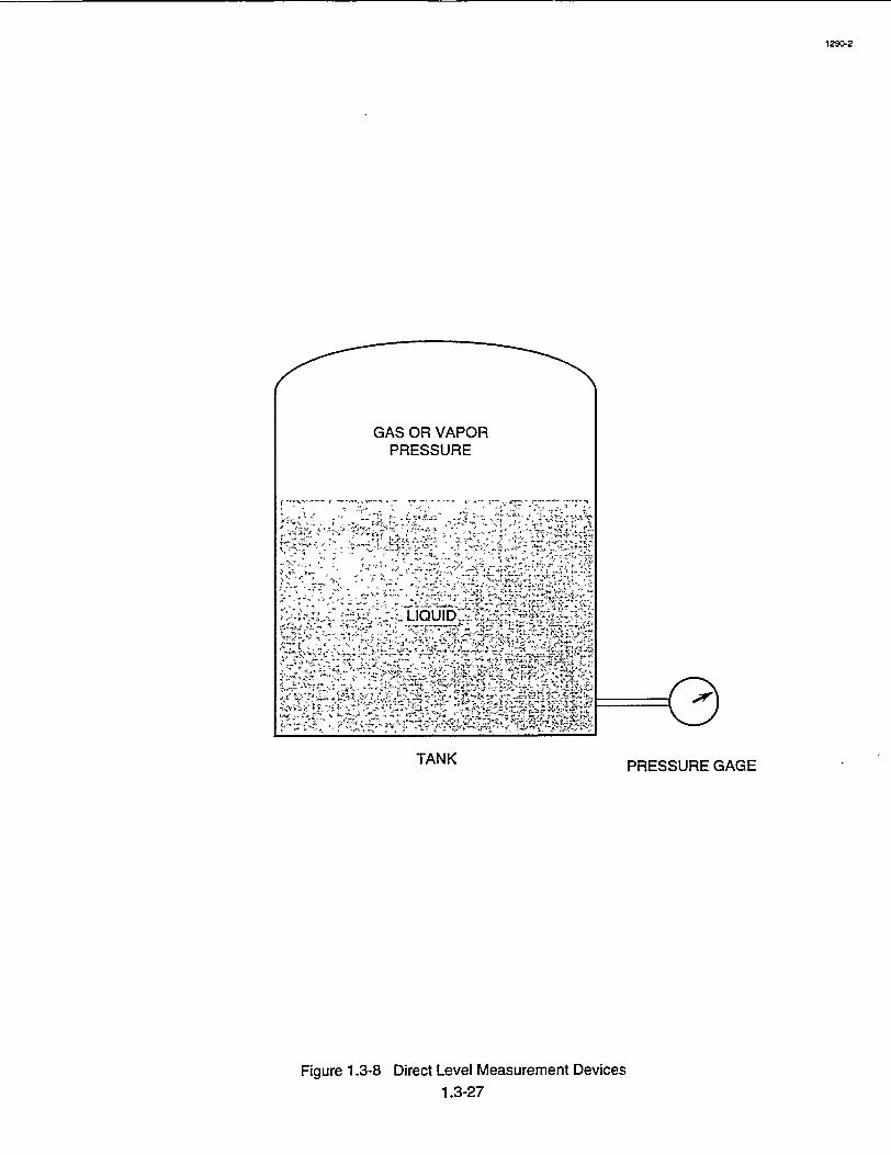
/4f
GAS O VAPO PRESSUR
TANK PRESSURE GAGE
Figure 1.3-8 Direct Level Measurement Devices
1.3-27
1290-2
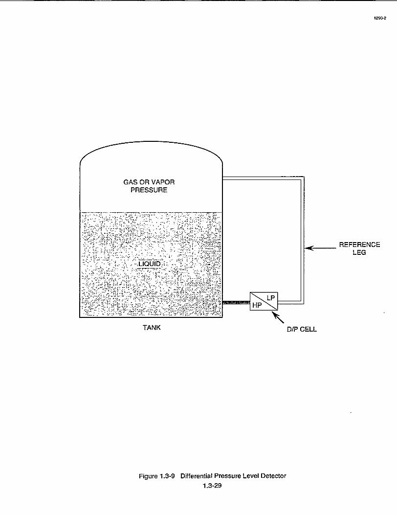
GAS OR VAPOR PRESSURE
-. .
J.2
TANK
REFERENCE LEG
D/P CELL
Figure 1.3-9 Differential Pressure Level Detector
1.3-29
1290-2
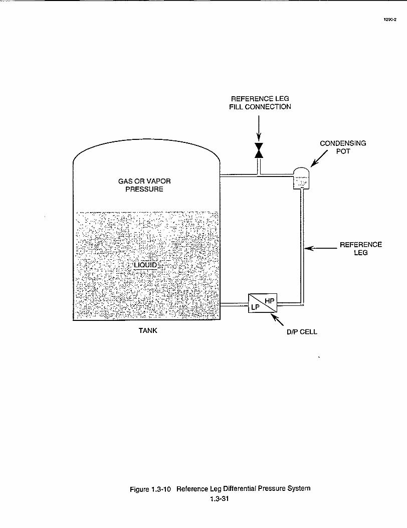
1290-2
REFERENCE LEG FILL CONNECTION
GAS OR VAPOR
PRESSURE
vt' ,-,
.7
TANK
CONDENSING I POT
REFERENCE LEG
D/P CELL
Figure 1.3-10 Reference Leg Differential Pressure System 1.3-31

mA METER TEST WIRING TERMINALS
EXTERNAL COVER
ISOLATING DIAPHRAGM O-RING
SENSING MODULE
PROCESS FLUID ISOLATING DIAPHRAGM
Figure 1.3-11 Variable Capacitance Dlifferential Pressure Sensor
1.3-33
105S-3
RETAINGIN' RING
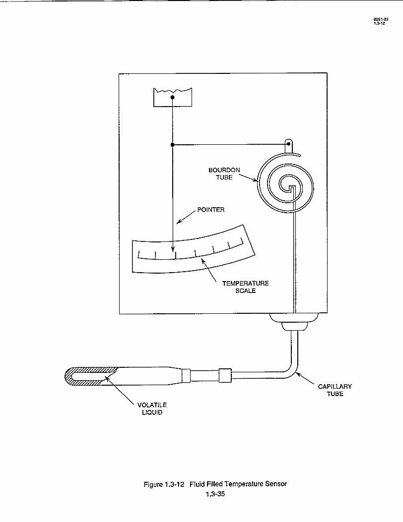
0291-23 1.3-12
CAPILLARY TUBE
VOLATILE LIQUID
Figure 1.3-12 Fluid Filled Temperature Sensor 1.3-35
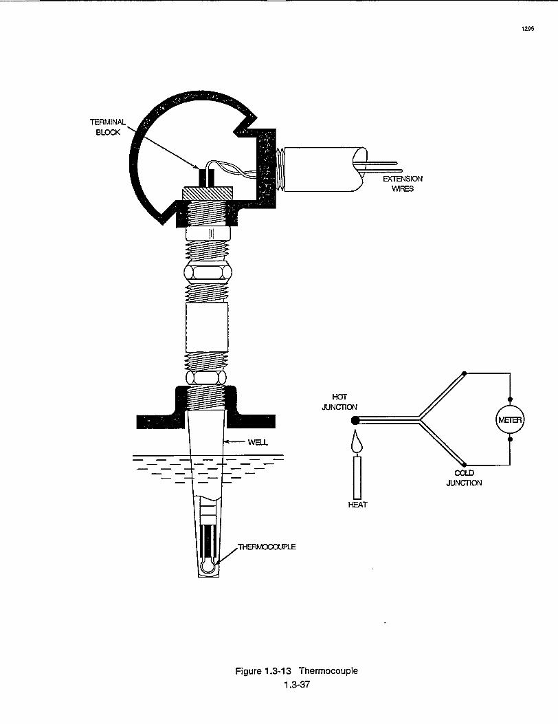
1295
TERMINAL BLOCK
EXTENSION WIRES
HOT JUNCTION
HEAT
Figure 1.3-13 Thermocouple
1.3-37
COLD JUNCTION
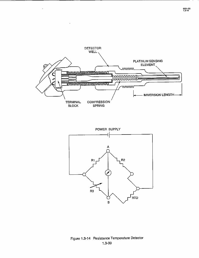
0291-23 1.3-14
DETECTOR WELL.
PLATINUM SENSING ELEMENT
-- • IMMERSION LENGTH
TERMINAL COMPRESSION BLOCK SPRING
POWER SUPPLY
Figure 1.3-14 Resistance Temperature Detector 1.3-39
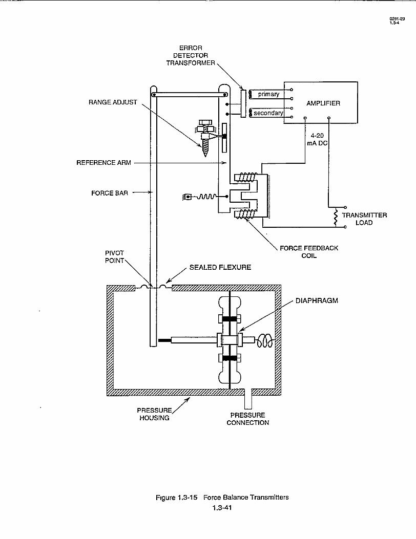
0291-23 1.3-4
ERROR DETECTOR
RANGE ADJUST
REFERENCE ARM
FORCE BAR -
PRESSURE HOUSING PRESSURE
CONNECTION
Figure 1.3-15 Force Balance Transmitters
1.3-41
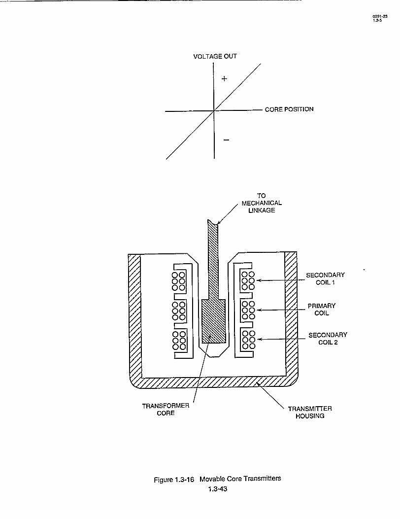
VOLTAGE OUT
CORE POSITION
TO MECHANICAL
LINKAGE
TRANSFORMER CORE
/ SECONDARY COIL 1
PRIMARY COIL
SECONDARY COIL 2
TRANSMITTER HOUSING
Figure 1.3-16 Movable Core Transmitters 1.3-43
1ý///11.1/1111
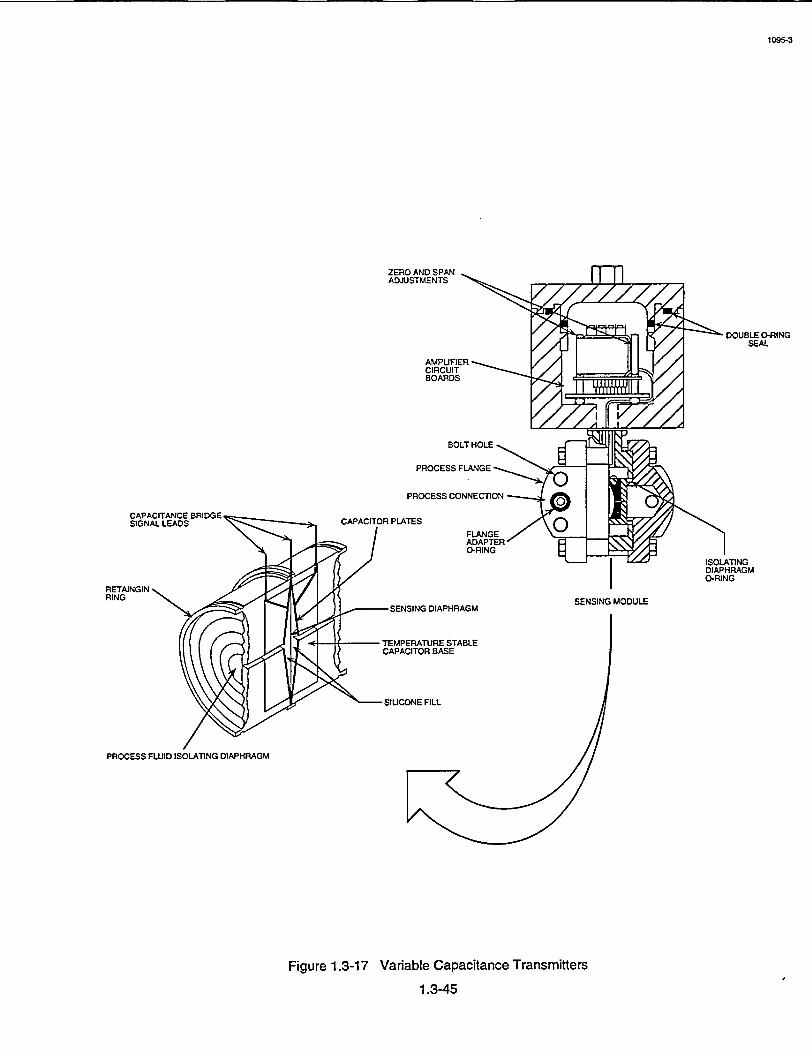
1095-3
ZERO AND SPAN ADJUSTMENTS
DOUBLE 0-RING SEAL
AMPLIFIER CIRCUIT BOARDS
SOLT HOLE
PROCESS FLANGE
PROCESS CONNECTION
CAPACITOR PLATES
ADAPTER O-RING
ISOLATING DIAPHRAGM
O-RING
SENSING MODULE SENSING DIAPHRAGM
TEMPERATURE STABLE CAPACITOR BASE
---- SIUCONE FILL
Figure 1.3-17 Variable Capacitance Transmitters
1.3-45

0391-23 1.3-15
DETECTOR
CONTROL ROOM
INDICATION
SETPOINT
CONTROLLER OUTPUT
or I CONTROLLER
DEVIATION INDICATION -1
SUMMING UNIT
TO CONTROLLED
DEVICE
Figure 1.3-18 Basic Control Diagram 1.3-47
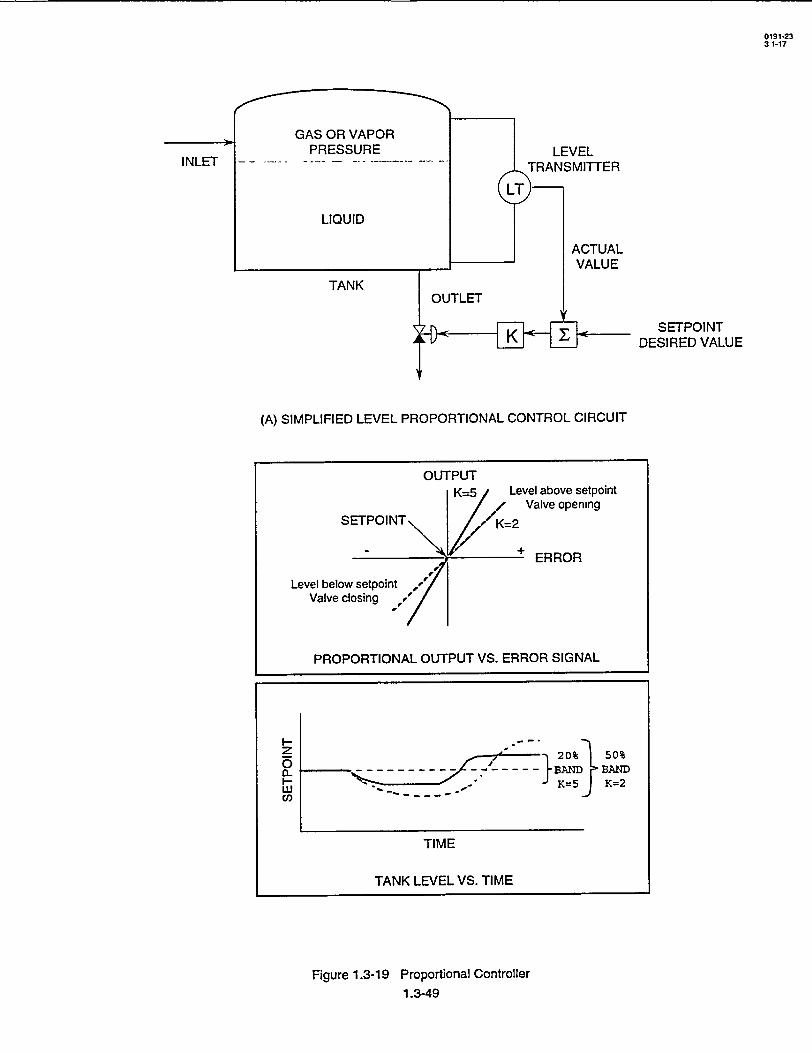
GAS OR VAPOR PRESSURE
LIQUID
TANK
LEVEL TRANSMITTER
ACTUAL VALUE
SETPOINT DESIRED VALUE
(A) SIMPLIFIED LEVEL PROPORTIONAL CONTROL CIRCUIT
Figure 1.3-19 Proportional Controller 1.3-49
INLET
0191-23 31-17
S-- - -- - -o -o
o B D I BA
w- J5J K=2 C/)
TIME
TANK LEVEL VS. TIME
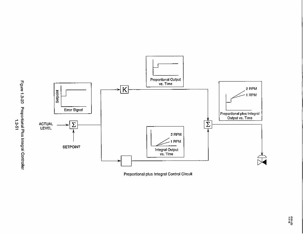
Prnnnrtinnal Ou tpniut(n ,-, vs. Time
S2 RPM
J I RPM
00
Error Signal Proportional plus Integral
:.. .Output vs. Time A CTUAL >_ I "22 LEVEL
"" 2 RPM
1 RPM CD SSETPOINT w Integral Output 0 vs. Time ,, 0
Proportional plus Integral Control Circuit
00

_______________________________ J
0 0
INPUT
63%
0 It t 0 t
OUTPUT
CD
CD -L
0 :.
(It
63%
INPUT
OUTPUT
0
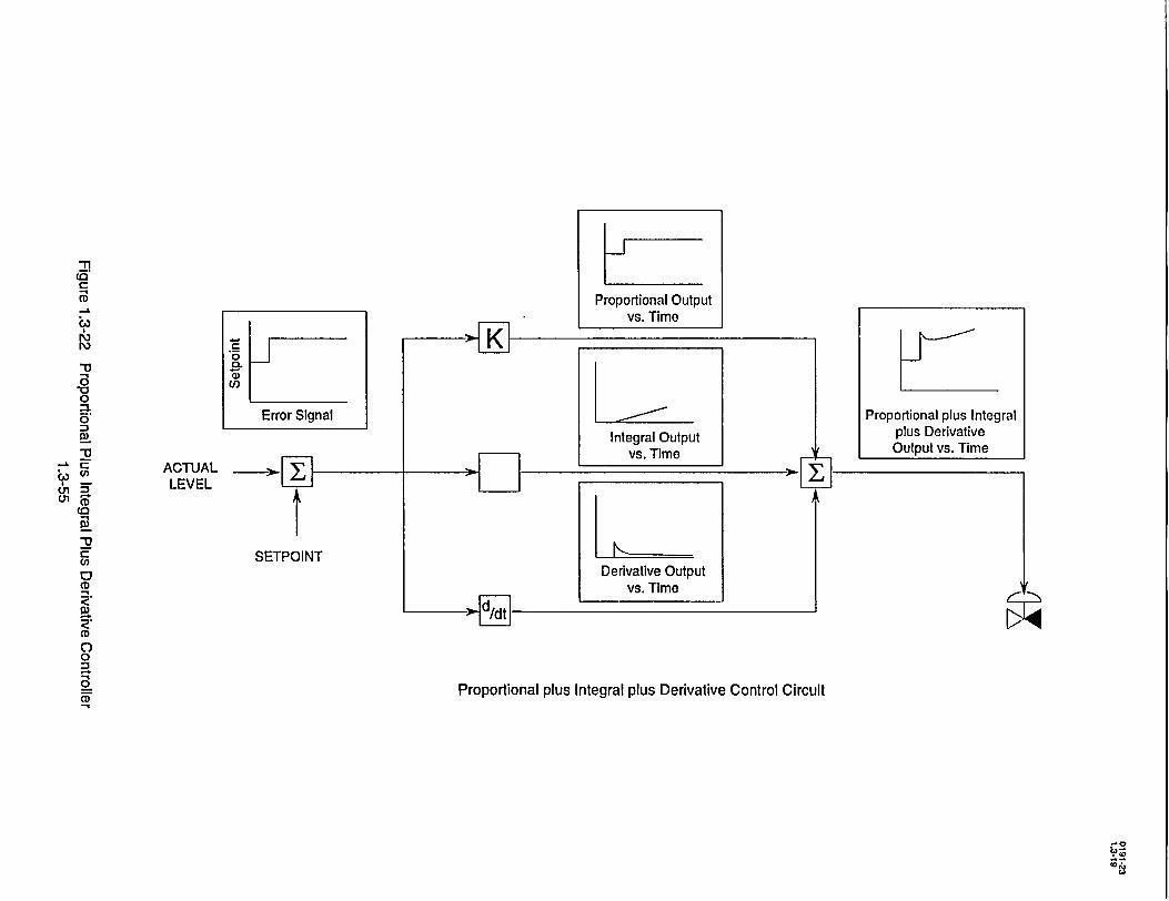
Error Signal
ACTUAL _._ LEVEL
SETPOINT
K 1-. 7.l
Proportional Output vs. Time
Integral Output vs. Time
Derivative Output vs. Time
41i-Proportional plus Integral
plus Derivative Output vs. Time
-L
10
roj ro
0
"-a
0
(a
i
0
R, CD (/)
0
0
CD
(,
L.,, 01 01
Proportional plus Integral plus Derivative Control Circuit
90

1290-23 1.3-21
INPUT t I t I -t I t
NEGATIVE NEGATIVE STEP STEP RAMP RAMP
PROPORTIONAL X t t t t
INTEGRAL t _,t • t 7
PI t~
DERIVATIVE t
PIDt
Figure 1.3-23 PID Controller Responses 1.3-57
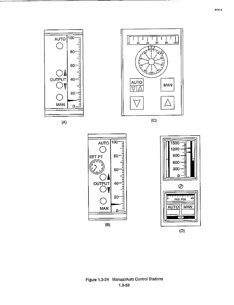
0191-2
60- ---s o
AUPU~o1 40 --- 1_ 111-1 80 90 0 10
80 20
60 - 70 30
05
OUTPUT 40 ATOL
O 20-
MAN 0-
(A) (C)
AUTO 100-- 1500-
O0 - 1200
SET PT 80-90
/,ý- 0 1600
60= 300
01 OUTPUT 40-
0! 20 .- 0RGPO 100
MAN AU [A
(B)
(D)
Figure 1.3-24 Manual/Auto Control Stations
1.3-59
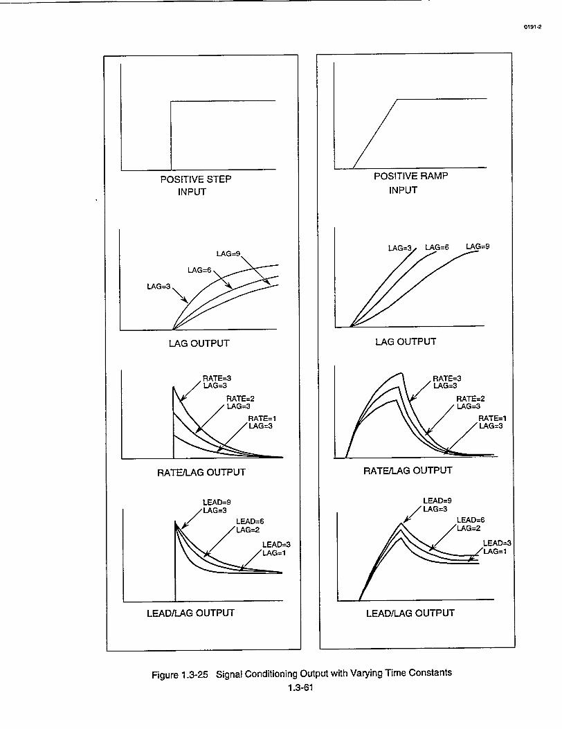
POSITIVE STEP INPUT
LAG OUTPUT
RATE/LAG OUTPUT
LEAD/LAG OUTPUT
Figure 1.3-25 Signal Conditioning Output with Varying Time Constants 1.3-61
0191-2
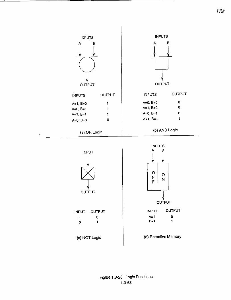
INPUTS A B
OUTPUT
INPUTS
A=l, B=O
A=O, B=1
A=l, B=1
A=O, B1=0
OUTPUT
1 1
1
0
(a) OR Logic
INPUT
OUTPUT
INPUT 1 0
OUTPUT 0 1
(c) NOT Logic
INPUTS
A B
OUTPUT
INPUTS
A=0, B=0
A=l, B=0
A=0, B=1
A=l, B=1
OUTPUT
0 0
0
1
(b) AND Logic
INPUTS A B
OUTPUT
INPUT OUTPUT
A=l 0 B=I 1
(d) Retentive Memory
Figure 1.3-26 Logic Functions 1.3-63
0191-23 13-22
- i
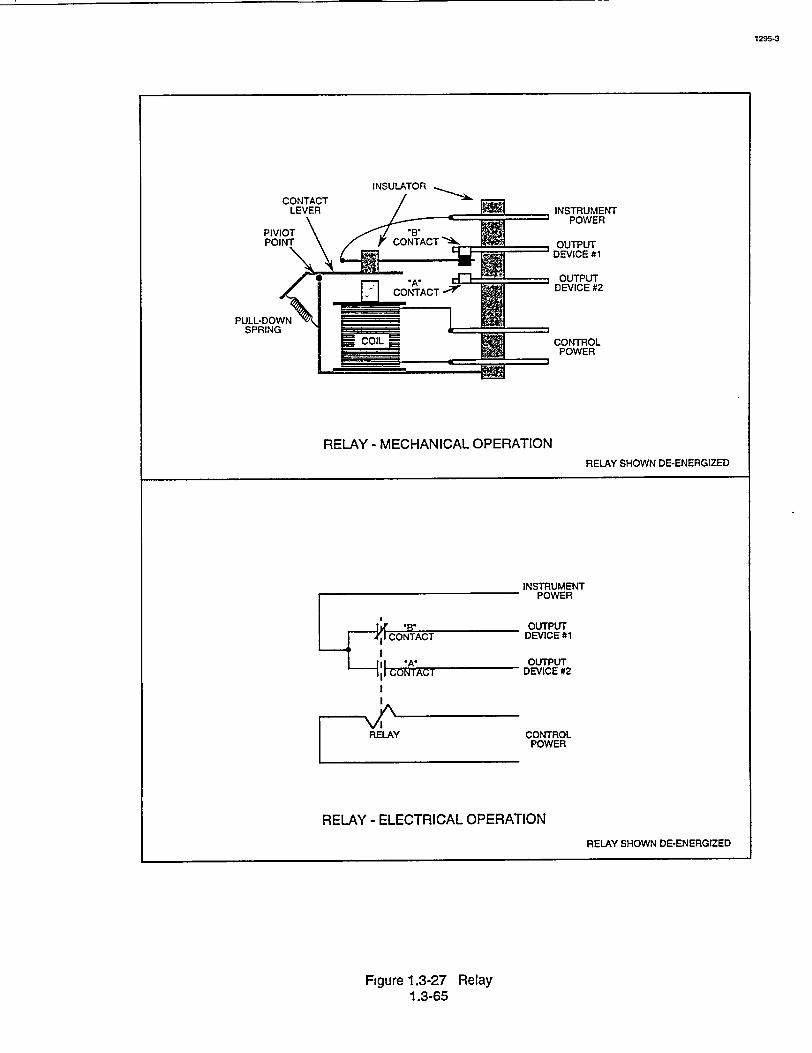
INSTRUMENT POWER
OUTPUT DEVICE #1
OUTPUT DEVICE #2
CONTROL POWER
RELAY - MECHANICAL OPERATION
RELAY SHOWN DE-ENERGIZED
INSTRUMENT POWER
OUTPUT CONTACT DEVICE #1
CON A"I OUTPUT
,I z-&(;IDEVICE #2
RKLAY CONTROL POWER
RELAY - ELECTRICAL OPERATION
RELAY SHOWN DE-ENERGIZED
Figure 1.3-27 Relay 1.3-65
1295-3
PULL-DOWN SPRING