Embed Size (px)
Citation preview
02610-1
Project Name Issue Date: ______________
SECTION 02610
PIPE & FITTINGS
PART 1 – GENERAL
1.1 SUMMARY
02610-2
Project Name Issue Date: ______________
A. CONTRACTOR shall provide all labor, materials, equipment, incidentals, and services as shown, specified, and required for furnishing, installing, and testing all buried piping, fittings, and specials specified herein. Piping herein specified includes force main & gravity sewer for sanitary and storm applications. Remove and replace all existing piping that interferes with installation of new pipe or structures or that is damaged by new installations in a manner approved by the ENGINEER.
B. The work includes, but is not limited to, the following:
1. Piping beneath structures.
02610-3
Project Name Issue Date: ______________
2. Supports and restraints.
3. Pipe encasements.
4. Work on or affecting existing piping.
5. Testing.
6. Cleaning and disinfecting.
02610-4
Project Name Issue Date: ______________
7. Installation of all jointing and gasketing materials, specials, flexible couplings,mechanical couplings, harnessed and flanged adapters, sleeves, tie rods, and all other work required to complete the buried piping installation.
8. Incorporation of valves, meters and special items shown or specified into the piping systems as required.
9. Unless otherwise specifically shown, specified, or included under other Sections, all buried piping work required, beginning at the outside face of structures or structure foundations and extending away from structure.
C. Review installation procedures under other Sections and other contracts and coordinate with the work that is related to this Section.
02610-5
Project Name Issue Date: ______________
1.2 RELATED WORK
1. Section 02110, Clearing and Grubbing
2. Section 02220, Excavation and Backfill
3. Section02606, Sanitary & Storm Structures
02610-6
Project Name Issue Date: ______________
4. Section 03300, Cast-In-Place Concrete
5. Section 09900, Painting
6. Division 15, Sections on Piping, Valves & Appurtenances
7. Section 15052, Exposed Piping Installation
8. Section 15100, Valves and Appurtenances
9. Section 15121, Wall Pipes, Floor Pipes and Pipe Sleeves
02610-7
Project Name Issue Date: ______________
10. Section 15122, Piping Specialties
11. Section 15140, Pipe Hangers and Supports
1.3 LIMITATIONS
A. All existing piping as shown on the Design Drawings is based on the best informationavailable, but SD1 and the ENGINEER makes no guarantees as to the accuracy of thelocations or type of piping depicted. All new piping which ties into existing lines must be made compatible with that piping. So that piping conflicts may be avoided, CONTRACTOR shall open up his trench well ahead of the pipe laying operation to confirm exact locations and sizes of existing piping before installing any new piping.
02610-8
Project Name Issue Date: ______________
CONTRACTOR shall provide all fittings and adapters necessary to complete all connections to existing piping as approved by SD1.
1.4 QUALITY ASSURANCE
Requirements of Regulatory Agencies:
A. Comply with requirements of UL, FM and other jurisdictional authorities, where applicable.
02610-9
Project Name Issue Date: ______________
B. Refer to the General and Supplementary Conditions regarding permit requirements for this Project.
1.5 REFERENCES
Comply with applicable provisions and recommendations of the following, except as otherwise shown or specified:
02610-10
Project Name Issue Date: ______________
A. AWWA C104, Standard for Cement-Mortar Lining for Ductile-Iron Pipe and Fittings for Water.
B. AWWA C105, Polyethylene Encasement for Ductile-Iron Piping for Water and OtherLiquids
C. AWWA C110, Standard for Ductile-Iron and Gray-Iron Fittings, 3 In.-48 In. (76 mm-1,219 mm), for Water.
02610-11
Project Name Issue Date: ______________
D. AWWA C111, Rubber‑Gasket Joints for Ductile‑Iron Pressure Pipe and Fittings
E. AWWA C115, Standard for Flanged Ductile-Iron Pipe with Ductile-Iron or Gray-IronThreaded Flanges.
F. AWWA C150, Standard for Thickness Design of Ductile-Iron Pipe.
02610-12
Project Name Issue Date: ______________
G. AWWA C151, Standard for Ductile-Iron Pipe, Centrifugally Cast, for Water.
H. AWWA C600, Installation of Ductile-Iron Water Mains and Their Appurtenances.
I. AWWA C606, Grooved and Shouldered Joints.
02610-13
Project Name Issue Date: ______________
J. AWWA C800, Underground Service Line Valves and Fittings.
K. AWWA C900, Polyvinyl Chloride (PVC) Pressure Pipe, and Fabricated Fittings, 4 In.-12 In. (100 mm-300 mm), for Water Dist.
L. AWWA M23, PVC—Design and Installation
02610-14
Project Name Issue Date: ______________
M. ASTM A 27, Standard Specification for Steel Castings, Carbon, for General Application.
N. ASTM A 82, Standard Specification for Steel Wire, Plain for Concrete Reinforcement.
O. ASTM A 185, Welded Steel Wire Fabric for Concrete Reinforcement.
P. ASTM A 496, Deformed Steel Wire for Concrete Reinforcement.
02610-15
Project Name Issue Date: ______________
Q. ASTM A 497, Steel Welded Wire Fabric, Deformed for Concrete Reinforcement.
R. ASTM A 1011, Steel, Sheet and Strip, Hot-Rolled, Carbon, Structural, High-Strength Low-Alloy, High-Strength Low-Alloy with Improved Formability, and Ultra-High Strength.
S. ASTM A 615, Standard Specification for Deformed and Plain Billet Steel Bars for Concrete Reinforcement.
02610-16
Project Name Issue Date: ______________
T. ASTM C 14, Standard Specification for Concrete Sewer, Storm Drain and Culvert Pipe.
U. ASTM C 76, Standard Specification for Reinforced Concrete Culvert, Storm Drain and Sewer Pipe.
V. ASTM C 118, Concrete Pipe for Irrigation or Drainage.
W. ASTM C 150, Standard Specification for Portland Cement
02610-17
Project Name Issue Date: ______________
X. ASTM C 361, Standard Specification for Reinforced Concrete Low‑Head Pressure Pipe.
Y. ASTM C 443, Standard Specification for Joints for Concrete Pipe and Manholes, Using Rubber Gaskets.
Z. ASTM C 478, Standard Specification for Precast Reinforced Concrete Manhole Sections.
02610-18
Project Name Issue Date: ______________
AA. ASTM D 1238, Measuring Flow Rates of Thermoplastics by Extrusion Plastometer.
BB. ASTM D 1598, Time-to-Failure of Plastic Pipe Under Constant Internal Pressure.
CC. ASTM D 1599, Short Time Hydraulic Failure Pressure of Plastic Pipe, Tubing, and Fittings.
02610-19
Project Name Issue Date: ______________
DD. ASTM D 1784, Rigid Poly (Vinyl Chloride) (PVC) Compounds and Chlorinated Poly(Vinyl Chloride) (CPVC) Compounds.
EE. ASTM D 1785, Standard Specification for Poly (Vinyl Chloride) (PVC) Plastic Pipe, Schedules 40, 80, and 120
FF. ASTM D 2122, Determining Dimensions of Thermoplastic Pipe and Fittings

02610-20
Project Name Issue Date: ______________
GG. ASTM D 2412, Standard Test Method for Determination of External Loading Characteristics of Plastic Pipe by Parallel-Plate Loading.
HH. ASTM D 2464, Threaded Poly (Vinyl Chloride) (PVC) Plastic Pipe Fittings, Schedule 80.
II. ASTM D 2467, Standard Specification for Poly (Vinyl Chloride) (PVC) Plastic Pipe Fittings, Schedule 80.

02610-21
Project Name Issue Date: ______________
JJ. ASTM D 2564, Standard Specification for Solvent Cements for Poly (Vinyl Chloride)(PVC) Plastic Piping Systems.
KK. ASTM D 2774, Practice for Underground Installation of Thermoplastic Pressure Piping.
LL. ASTM D 3034, Bell and Spigot‑Type Poly (Vinyl Chloride) (PVC) Plastic Pipe and Fittings.
02610-22
Project Name Issue Date: ______________
MM. ASTM D 3212, Standard Specification for Joints for Drain and Sewer Plastic Pipes Using Flexible Elastomeric Seals
NN. ASTM D 3261, Butt Heat Fusion Polyethylene (PE) Plastic Fittings for Polyethylene (PE) Plastic Pipe and Tubing.
OO. ASTM D 3262, Standard Specification for Fiberglass (Glass-Fiber-Reinforced Thermosetting-Resin) Sewer Pipe.
02610-23
Project Name Issue Date: ______________
PP. ASTM D 3350, Standard Specification for Polyethylene Plastics Pipe and Fittings Materials.
QQ. ASTM D 3754, “Fiberglass” (Glass-Fiber-Reinforced-Thermosetting-Resin) Sewer and Industrial Pressure Pipe.
RR. ASTM D 4161 Standard Specification for Fiberglass (Glass-Fiber-Reinforced Thermosetting-Resin) Pipe Joints Using Flexible Elastomeric Seals.
02610-24
Project Name Issue Date: ______________
SS. ASTM D 5685, “Fiberglass” (Glass-Fiber-Reinforced-Thermosetting-Resin) PressurePipe Fittings.
TT. ASTM F 437, Threaded Chlorinated Poly (Vinyl Chloride) (CPVC) Plastic Pipe Fittings, Schedule 80.
UU. ASTM F 439, Socket-Type Chlorinated Poly (Vinyl Chloride) (CPVC) Plastic Pipe Fittings, Schedule 80.
VV. ASTM F 441, Chlorinated Poly (Vinyl Chloride) (CPVC) Plastic Pipe and Fittings.
02610-25
Project Name Issue Date: ______________
WW. ASTM F 493, Solvent Cements for Chlorinated Poly (Vinyl Chloride) (CPVC) PlasticPipe and Fittings.
XX. ASTM F 714, Polyethylene (PE) Plastic Pipe (SDR-PR) Based on Outside Diameter.
YY. ASCE MOP No. 37, Design and Construction of Sanitary and Storm Sewers
02610-26
Project Name Issue Date: ______________
ZZ. ASTM C 507, Standard Specification for Reinforced Concrete Elliptical Culvert, Storm Drain and Sewer Pipe
AAA. ASTM F 679, Standard Specification for Polyvinyl Chloride (PVC) Large-Diameter Plastic Gravity Sewer Pipe and Fittings
BBB. ASTM F 794, Standard Specification for Polyvinyl Chloride (PVC) Profile Gravity Sewer Pipe and Fittings Based on Controlled Inside Diameter
02610-27
Project Name Issue Date: ______________
CCC. ASTM F 949, Standard Specification for Polyvinyl Chloride (PVC) Corrugated Sewer Pipe with Smooth Interior and Fittings
DDD. ASTM F 477, Standard Specification for Elastomeric Seals (Gaskets) for Joining Plastic Pipe
EEE. ASTM F 2306, Standard Specification for 12-60 inch Annular Corrugated Profile-Wall Polyethylene (PE) Pipe and Fittings for Gravity-Flow Storm Sewer and Subsurface Drainage Applications
02610-28
Project Name Issue Date: ______________
FFF. ASTM D 2321, Standard Practice for Underground Installation of Thermoplastic Pipefor Sewers and Other Gravity-Flow Applications
1.6 SUBMITTALS
A. In addition to the requirements of Section 01300, provide the following:
1. Size, class and other details of pipe to be used.
02610-29
Project Name Issue Date: ______________
2. Full details of piping, specials, joints, harnessing, and connections to existingpiping, structures, equipment and appurtenances.
B. Tests: Submit description of proposed testing methods, procedures and apparatus. Prepare and submit report for each test.
C. Certificates: Submit certificates of compliance with referenced standards.
02610-30
Project Name Issue Date: ______________
D. As requested by SD1, all pipe manufacturers that supply pipe for the project shall provide a detailed structural design taking in account the depth of burial, highway loads, bedding and backfill requirements, water elevation, soil conditions and installation procedures. All designs submitted shall have a Professional ENGINEER’s stamp from Kentucky. Such design shall be received, reviewed, and approved prior to manufacture.
E. As requested by SD1, pipe manufacturer for each pipe type used shall be present and instruct CONTRACTOR on proper installation technique per shop drawings and manufacturer’s recommended procedures. As requested by SD1, pipe manufacturer’srepresentative shall visit job site to monitor progress of pipe installation and shall notify in writing the CONTRACTOR and SD1 of any discrepancy, changes, or incorrect procedures that would prevent the pipe from performing as designed.
02610-31
Project Name Issue Date: ______________
F. Record Drawings: Submit record drawings in accordance with Section 01720 and Section 01721.
PART 2 – PIPING & FITTINGS
2.1 MATERIALS
02610-32
Project Name Issue Date: ______________
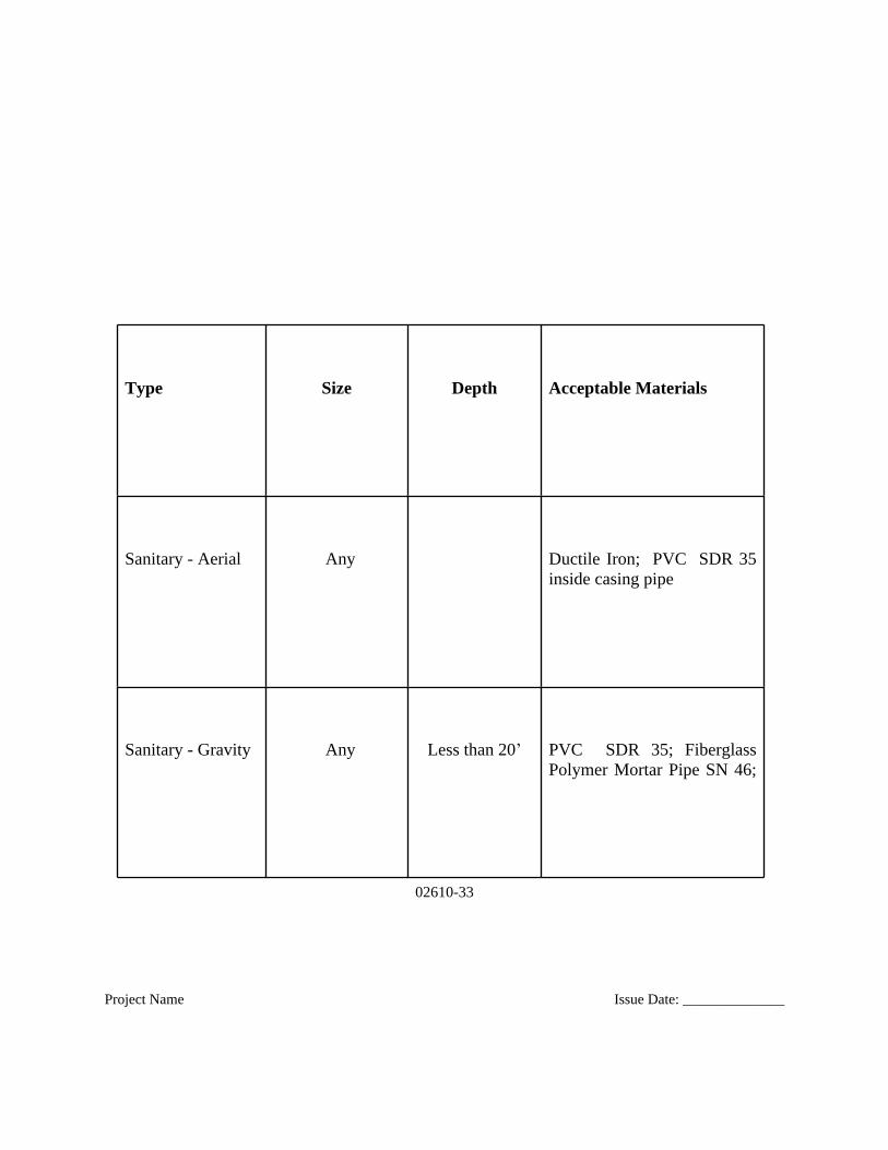
A. Piping herein specified includes force main & gravity sewer. Refer to the pipe material schedule shown below to determine which pipe materials are acceptable for each application.
02610-33
Project Name Issue Date: ______________
Type Size Depth Acceptable Materials
Sanitary - Aerial Any Ductile Iron; PVC SDR 35inside casing pipe
Sanitary - Gravity Any Less than 20’ PVC SDR 35; FiberglassPolymer Mortar Pipe SN 46;
02610-34
Project Name Issue Date: ______________
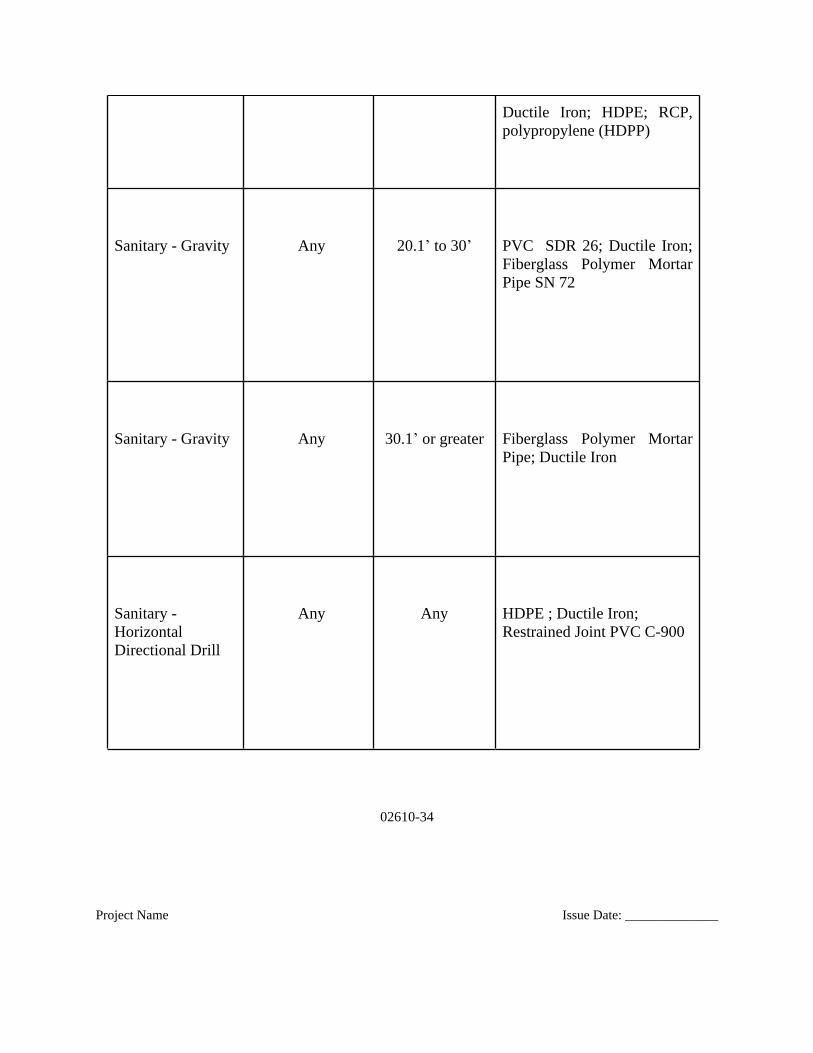
Ductile Iron; HDPE; RCP,polypropylene (HDPP)
Sanitary - Gravity Any 20.1’ to 30’ PVC SDR 26; Ductile Iron;Fiberglass Polymer MortarPipe SN 72
Sanitary - Gravity Any 30.1’ or greater Fiberglass Polymer MortarPipe; Ductile Iron
Sanitary - Horizontal Directional Drill
Any Any HDPE ; Ductile Iron; Restrained Joint PVC C-900
02610-35
Project Name Issue Date: ______________
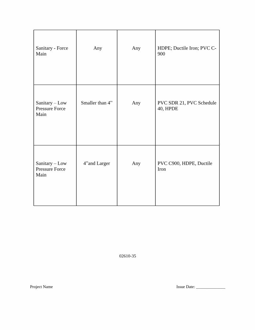
Sanitary - Force Main
Any Any HDPE; Ductile Iron; PVC C-900
Sanitary – Low Pressure Force Main
Smaller than 4” Any PVC SDR 21, PVC Schedule40, HPDE
Sanitary – Low Pressure Force Main
4”and Larger Any PVC C900, HDPE, Ductile Iron
02610-36
Project Name Issue Date: ______________
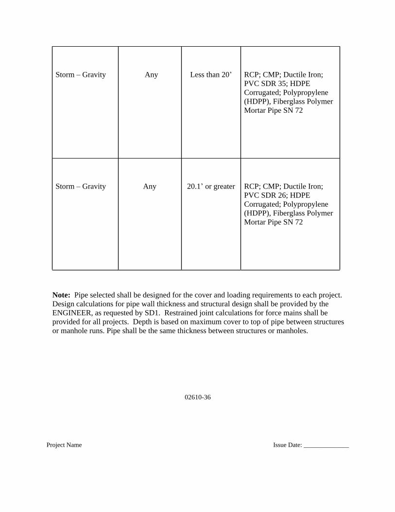
Storm – Gravity Any Less than 20’ RCP; CMP; Ductile Iron; PVC SDR 35; HDPE Corrugated; Polypropylene (HDPP), Fiberglass Polymer Mortar Pipe SN 72
Storm – Gravity Any 20.1’ or greater RCP; CMP; Ductile Iron; PVC SDR 26; HDPE Corrugated; Polypropylene (HDPP), Fiberglass Polymer Mortar Pipe SN 72
Note: Pipe selected shall be designed for the cover and loading requirements to each project. Design calculations for pipe wall thickness and structural design shall be provided by the ENGINEER, as requested by SD1. Restrained joint calculations for force mains shall be provided for all projects. Depth is based on maximum cover to top of pipe between structures or manhole runs. Pipe shall be the same thickness between structures or manholes.
02610-37
Project Name Issue Date: ______________
B. Refer to applicable Sections for material specifications.
C. General:
1. Marking Piping:
a. Cast or paint material, type and pressure designation on each piece ofpipe or fitting 4 inches in diameter and larger.
02610-38
Project Name Issue Date: ______________
b. Pipe and fittings smaller than 4 inches in diameter shall be clearlymarked by manufacturer as to material, type and rating.
2.2 DUCTILE IRON PIPE AND FITTINGS
A. Piping furnished hereunder shall be complete with all joint gaskets, bolts, and nutsrequired for installation of valves and equipment furnished by others for installationunder this contract.

02610-39
Project Name Issue Date: ______________
B. Pipe Manufacturer’s Experience and Field Services.
1. All ductile iron pipe, fittings, and specials shall be fabricated, lined and coatedby the pipe manufacturer. Minimum required experience shall includemanufacture of a similar pipeline in length to this contract, of equal or largerdiameter than the pipe to be provided with joints, lining, and coating suitablefor the same or greater pressure rating specified herein, which has performedsatisfactorily for the past 5 years.
2. An experienced, competent, and authorized field service representative shallbe provided by the pipe manufacturer to perform all pipe manufacturer’s fieldservices specified herein. The field service representative’s minimumrequired experience qualifications shall include 5 years of practical knowledgeand experience installing ductile iron pipe with joints, lining, and coating ofthe pipe to be provided.
02610-40
Project Name Issue Date: ______________
3. All ductile iron pipe shall be installed in accordance with the pipemanufacturer’s recommendations. The pipe manufacturer’s field servicerepresentative shall visit the site and inspect, check, instruct, guide, and directCONTRACTOR’s procedures for pipe handling and installation at the start ofthe pipe installation. The pipe manufacturer’s field service representativeshall coordinate his services with CONTRACTOR.
4. Each joint, including all restrained joints, shall be checked byCONTRACTOR as instructed by the pipe manufacturer’s field servicerepresentative to determine that the joint and the restraints are installedproperly.
5. As requested, the pipe manufacturer’s field service representative shall furnishto SD1, through ENGINEER, a written report certifying thatCONTRACTOR’s installation personnel have been properly instructed andhave demonstrated the proper pipe handling and installation procedures. Thepipe manufacturer’s field service representative shall also furnish to SD1,through ENGINEER, a written report of each site visit. The pipemanufacturer’s field service representative shall revisit the site as often asnecessary until all trouble is corrected and the pipeline installation andoperation are satisfactory in the opinion of the ENGINEER.
02610-41
Project Name Issue Date: ______________
6. All costs for these services shall be included in the Contract Price.
C. Materials
1. Where ductile iron pipe is required, it shall conform to ANSI/AWWA C151/A21.51, Table 1 or Table 3. Pressure class 350 shall be used for all piping, unless otherwise shown on the drawings or specified. Fittings shall conform to ANSI/AWWA C110/A21.10, or ANSI/AWWA C153/A21.53, witha minimum working pressure rating of 350 psi. All fittings shall be suitable fora test pressure as specified herein without leakage or damage.
2. All buried pressure piping shall be push-on joint or mechanical joint. Restrained joint pipe shall be installed at the station locations shown on the Contract Drawings. All above ground piping or piping in vaults shall be flanged.
02610-42
Project Name Issue Date: ______________
3. All gravity sewer piping shall be push-on joint or mechanical joint.
4. Push-on joints and mechanical joints shall be in accordance with ANSI/AWWA C111/A21.11.
5. As requested, restrained joint pipe shall be fabricated to the lengths required as determined by the laying schedule to be submitted as specified herein. If deviations from the approved laying schedule are required in the field as approved by SD1 and ENGINEER and field-cuts are required, CONTRACTOR shall provide restraint on the field-cut piping using, EBAA Iron “Megalug” restrained joints as specified below.
6. Field cuts shall be minimized and will be limited to only locations as necessaryto install pipe, when no other alternative to using factory provided joint restraint exists.

02610-43
Project Name Issue Date: ______________
D. Joints
1. Certification of joint design shall be provided in accordance with ANSI/AWWA C111/A21.11-90, Section 4.5, Performance Requirements, as modified herein.
2. The joint test pressure for each type of joint used on this project shall be 1-1/2 times the working pressure at the lowest elevation of the pipeline for a duration of two hours or as specified by the design engineer. The same certification and testing shall also be provided for restrained joints. For restrained joints, the piping shall not be blocked to prevent separation and the joint shall not leak or show evidence of failure.
3. It is not necessary that such tests be made on pipe manufactured specifically for this project. Certified reports covering tests made on other pipe of the same size and design as specified herein and on the drawings and manufactured from materials of equivalent type and quality may be accepted as adequate proof of design.
02610-44
Project Name Issue Date: ______________
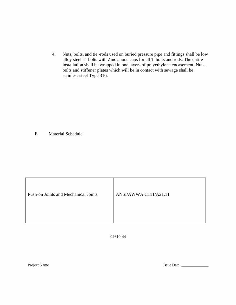
4. Nuts, bolts, and tie -rods used on buried pressure pipe and fittings shall be lowalloy steel T- bolts with Zinc anode caps for all T-bolts and rods. The entire installation shall be wrapped in one layers of polyethylene encasement. Nuts, bolts and stiffener plates which will be in contact with sewage shall be stainless steel Type 316.
E. Material Schedule
Push-on Joints and Mechanical Joints ANSI/AWWA C111/A21.11
02610-45
Project Name Issue Date: ______________
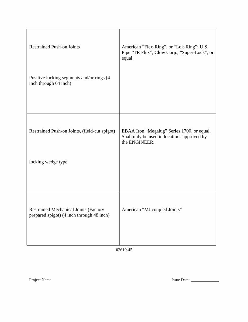
Restrained Push-on Joints
Positive locking segments and/or rings (4 inch through 64 inch)
American “Flex-Ring”, or “Lok-Ring”; U.S. Pipe “TR Flex”; Clow Corp., “Super-Lock”, orequal
Restrained Push-on Joints, (field-cut spigot)
locking wedge type
EBAA Iron “Megalug” Series 1700, or equal. Shall only be used in locations approved by the ENGINEER.
Restrained Mechanical Joints (Factory prepared spigot) (4 inch through 48 inch)
American “MJ coupled Joints”
02610-46
Project Name Issue Date: ______________
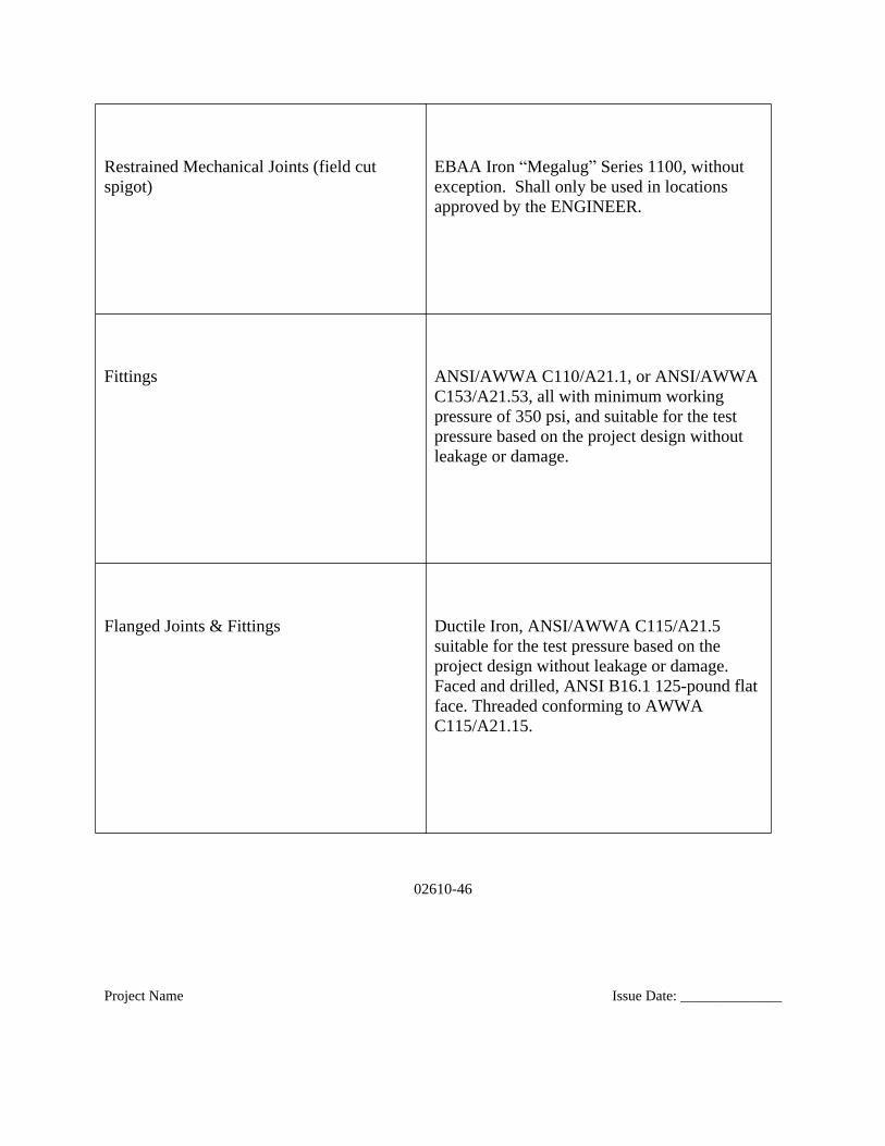
Restrained Mechanical Joints (field cut spigot)
EBAA Iron “Megalug” Series 1100, without exception. Shall only be used in locations approved by the ENGINEER.
Fittings ANSI/AWWA C110/A21.1, or ANSI/AWWAC153/A21.53, all with minimum working pressure of 350 psi, and suitable for the test pressure based on the project design without leakage or damage.
Flanged Joints & Fittings Ductile Iron, ANSI/AWWA C115/A21.5 suitable for the test pressure based on the project design without leakage or damage. Faced and drilled, ANSI B16.1 125-pound flat face. Threaded conforming to AWWA C115/A21.15.
02610-47
Project Name Issue Date: ______________
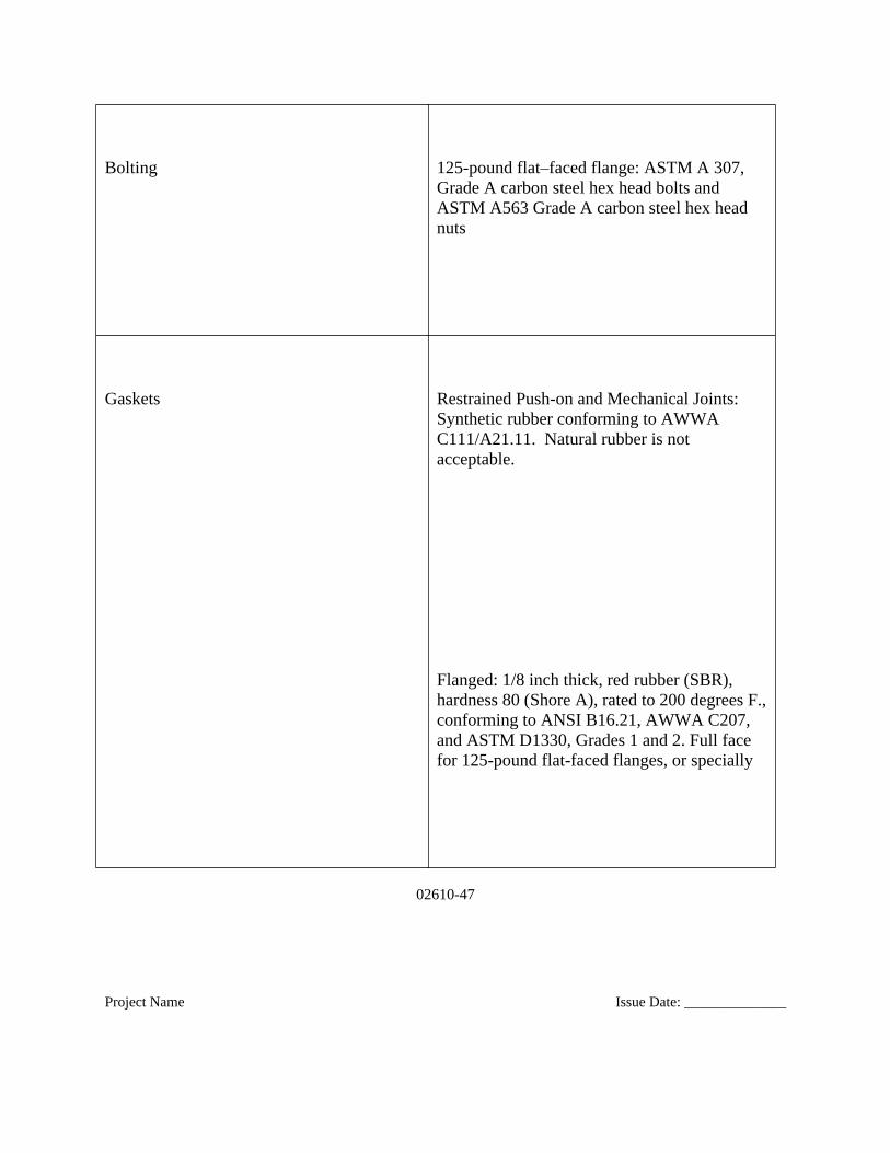
Bolting 125-pound flat–faced flange: ASTM A 307, Grade A carbon steel hex head bolts and ASTM A563 Grade A carbon steel hex head nuts
Gaskets Restrained Push-on and Mechanical Joints: Synthetic rubber conforming to AWWA C111/A21.11. Natural rubber is not acceptable.
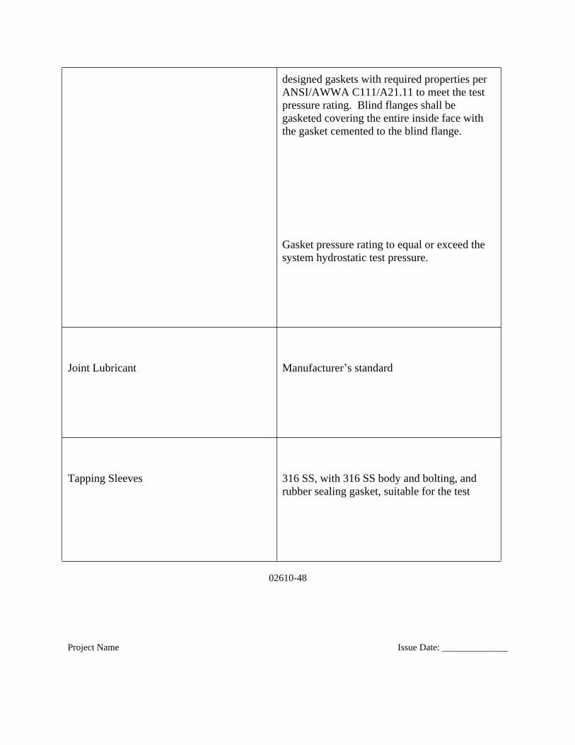
Flanged: 1/8 inch thick, red rubber (SBR), hardness 80 (Shore A), rated to 200 degrees F.,conforming to ANSI B16.21, AWWA C207, and ASTM D1330, Grades 1 and 2. Full face for 125-pound flat-faced flanges, or specially
02610-48
Project Name Issue Date: ______________
designed gaskets with required properties per ANSI/AWWA C111/A21.11 to meet the test pressure rating. Blind flanges shall be gasketed covering the entire inside face with the gasket cemented to the blind flange.
Gasket pressure rating to equal or exceed the system hydrostatic test pressure.
Joint Lubricant Manufacturer’s standard
Tapping Sleeves 316 SS, with 316 SS body and bolting, and rubber sealing gasket, suitable for the test
02610-49
Project Name Issue Date: ______________
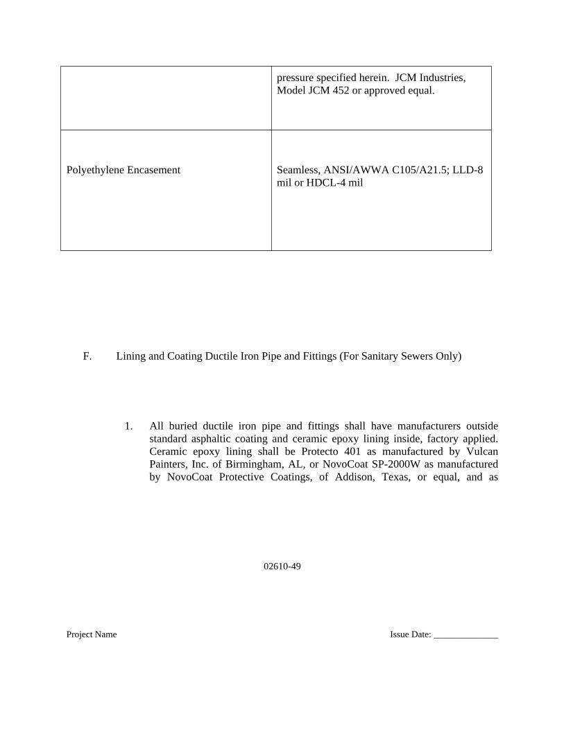
pressure specified herein. JCM Industries, Model JCM 452 or approved equal.
Polyethylene Encasement Seamless, ANSI/AWWA C105/A21.5; LLD-8mil or HDCL-4 mil
F. Lining and Coating Ductile Iron Pipe and Fittings (For Sanitary Sewers Only)
1. All buried ductile iron pipe and fittings shall have manufacturers outsidestandard asphaltic coating and ceramic epoxy lining inside, factory applied.Ceramic epoxy lining shall be Protecto 401 as manufactured by VulcanPainters, Inc. of Birmingham, AL, or NovoCoat SP-2000W as manufacturedby NovoCoat Protective Coatings, of Addison, Texas, or equal, and as
02610-50
Project Name Issue Date: ______________
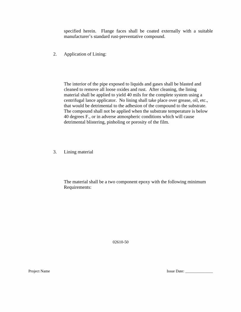
specified herein. Flange faces shall be coated externally with a suitablemanufacturer’s standard rust-preventative compound.
2. Application of Lining:
The interior of the pipe exposed to liquids and gases shall be blasted and cleaned to remove all loose oxides and rust. After cleaning, the lining material shall be applied to yield 40 mils for the complete system using a centrifugal lance applicator. No lining shall take place over grease, oil, etc., that would be detrimental to the adhesion of the compound to the substrate. The compound shall not be applied when the substrate temperature is below 40 degrees F., or in adverse atmospheric conditions which will cause detrimental blistering, pinholing or porosity of the film.
3. Lining material
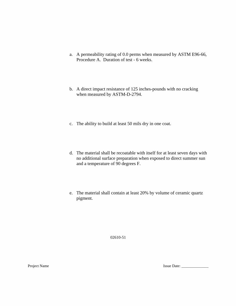
The material shall be a two component epoxy with the following minimum Requirements:
02610-51
Project Name Issue Date: ______________
a. A permeability rating of 0.0 perms when measured by ASTM E96-66, Procedure A. Duration of test - 6 weeks.
b. A direct impact resistance of 125 inches-pounds with no cracking when measured by ASTM-D-2794.
c. The ability to build at least 50 mils dry in one coat.
d. The material shall be recoatable with itself for at least seven days with no additional surface preparation when exposed to direct summer sun and a temperature of 90 degrees F.
e. The material shall contain at least 20% by volume of ceramic quartz pigment.
02610-52
Project Name Issue Date: ______________
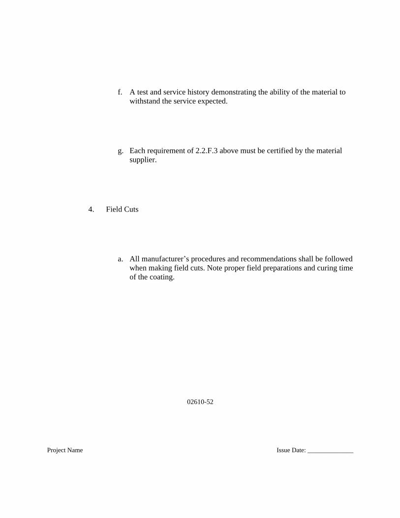
f. A test and service history demonstrating the ability of the material to withstand the service expected.
g. Each requirement of 2.2.F.3 above must be certified by the material supplier.
4. Field Cuts
a. All manufacturer’s procedures and recommendations shall be followedwhen making field cuts. Note proper field preparations and curing timeof the coating.
02610-53
Project Name Issue Date: ______________
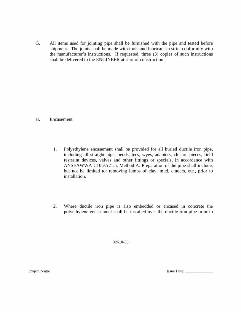
G. All items used for jointing pipe shall be furnished with the pipe and tested beforeshipment. The joints shall be made with tools and lubricant in strict conformity withthe manufacturer’s instructions. If requested, three (3) copies of such instructionsshall be delivered to the ENGINEER at start of construction.
H. Encasement
1. Polyethylene encasement shall be provided for all buried ductile iron pipe,including all straight pipe, bends, tees, wyes, adapters, closure pieces, fieldrestraint devices, valves and other fittings or specials, in accordance withANSI/AWWA C105/A21.5, Method A. Preparation of the pipe shall include,but not be limited to: removing lumps of clay, mud, cinders, etc., prior toinstallation.
2. Where ductile iron pipe is also embedded or encased in concrete thepolyethylene encasement shall be installed over the ductile iron pipe prior to
02610-54
Project Name Issue Date: ______________
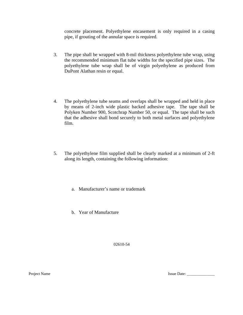
concrete placement. Polyethylene encasement is only required in a casingpipe, if grouting of the annular space is required.
3. The pipe shall be wrapped with 8-mil thickness polyethylene tube wrap, usingthe recommended minimum flat tube widths for the specified pipe sizes. Thepolyethylene tube wrap shall be of virgin polyethylene as produced fromDuPont Alathan resin or equal.
4. The polyethylene tube seams and overlaps shall be wrapped and held in placeby means of 2-inch wide plastic backed adhesive tape. The tape shall bePolyken Number 900, Scotchrap Number 50, or equal. The tape shall be suchthat the adhesive shall bond securely to both metal surfaces and polyethylenefilm.
5. The polyethylene film supplied shall be clearly marked at a minimum of 2-ftalong its length, containing the following information:
a. Manufacturer’s name or trademark
b. Year of Manufacture
02610-55
Project Name Issue Date: ______________
c. ANSI/AWWA C105/A21.5
d. Minimum film thickness and material type (LLDPE or HDCLPE)
e. Applicable range of nominal pipe diameter size(s)
f. Warning--Corrosion Protection--Repair any Damage
2.3 POLYVINYL CHLORIDE (PVC) PIPE AND FITTINGS (GRAVITY LINES)
02610-56
Project Name Issue Date: ______________
A. Polyvinyl Chloride (PVC) and Chlorinated Polyvinyl Chloride (CPVC) Piping –
Schedule Rated Pipe:
1. Pipe and Fitting Material:
a. Standard: ASTM D 1784.
b. Type: Type I, Grade 1, rigid (12454‑B).
2. Pipe:
02610-57
Project Name Issue Date: ______________
a. PVC:
1) Standard: ASTM D 1785.
2) Designation: PVC 1120.
b. CPVC:
1) Standard: ASTM F 441.
3. Joints:
02610-58
Project Name Issue Date: ______________
a. General: Connect pipe by solvent cementing except where flanged or threaded fittings are required at expansion joints, valves, flow meters, equipment connections or otherwise shown or directed.
b. Flanged Joints:
1) Use flanges joined to pipe by solvent cementing.
2) Flange Drilling and Dimensions: Comply with ANSI B16.1.
3) Flange Gaskets: Viton full face.
4) Bolts, Nuts and Washers: Type 316 stainless steel.
02610-59
Project Name Issue Date: ______________
5) Provide washers on each face of the bolted connection.
c. Threaded Joints:
1) Taper Pipe Threads: ANSI B2.1.
2) Joint Preparation: Teflon tape.
3) Use PVC dies for taper pipe threads.
d. Primer and Solvent Cement:
02610-60
Project Name Issue Date: ______________
1) Standard:
a) PVC: ASTM D 2564.
b) CPVC: ASTM F 493.
4. Fittings:
a. Socket‑Type:
1) PVC:

02610-61
Project Name Issue Date: ______________
a) Standard: ASTM D 2467.
b) Designation: PVC I.
2) CPVC:
a) Standard: ASTM F 439.
b) Threaded Type:
i. PVC:
02610-62
Project Name Issue Date: ______________
(a) Standard: ASTM D 2464.
(b) Designation: PVC I.
ii. CPVC:
(a) Standard: ASTM F 437.
B. Polyvinyl Chloride (PVC) Piping – Gravity Sewer Pipe and Fittings:

02610-63
Project Name Issue Date: ______________
1. Pipe and Fitting Material:
a. Standard: ASTM D 1784.
2. Pipe and Fittings:
a. Standard:
1) 4-inch through 15-inch diameter: ASTM D 3034.
2) 18-inch through 27-inch diameter: ASTM F 679.
02610-64
Project Name Issue Date: ______________
b. Thickness Class: As shown in item 1.1 this section.
3. Joints:
a. Push On Joints: Connect pipe with integral wall bell and spigot joints.The bell shall consist of an integral wall section with a solid crosssection rubber gasket, factory assembled, securely locked in place toprevent displacement during assembly. Joints shall be assembled inaccordance with the pipe manufacturer’s recommendations and ASTMD 3212.
b. Gaskets: Rubber gaskets shall be in compliance with ASTM F 477and shall be suitable for the service specified.
02610-65
Project Name Issue Date: ______________
C. Profile Wall Polyvinyl Chloride (PVC) Piping (For Storm Sewers Only)
1. PVC open or closed profile pipe meeting the requirements of ASTM F 794,Standard Specification for Polyvinyl Chloride (PVC) Profile Gravity SewerPipe and Fittings Based on Controlled Inside Diameter.
2. Joints for PVC pipe shall be gasket, bell and spigot, push-on types which meetthe requirements of ASTM D 3212, Standard Specification for Joints forDrain and Sewer Plastic Pipes Using Flexible Elastomeric Seals. Gaskets shallmeet the requirements of ASTM F 477, Standard Specification forElastomeric Seals (Gaskets) for Joining Plastic Pipe.
D. Corrugated Polyvinyl Chloride (PVC) Piping (For Storm Sewers Only)
02610-66
Project Name Issue Date: ______________
1. Corrugated PVC pipe meeting the requirements of ASTM F 949, LatestRevision, "Polyvinyl Chloride (PVC) Corrugated Sewer Pipe with a SmoothInterior and Fittings".
2. Joints for PVC pipe shall be gasket, bell and spigot, push-on types which meetthe requirements of ASTM D 3212, Standard Specification for Joints forDrain and Sewer Plastic Pipes Using Flexible Elastomeric Seals. Gaskets shallmeet the requirements of ASTM F 477, Standard Specification forElastomeric Seals (Gaskets) for Joining Plastic Pipe.
02610-67
Project Name Issue Date: ______________
2.4 POLYVINYL CHLORIDE (PVC) PIPE – C900 PIPING (FORCE MAINS)
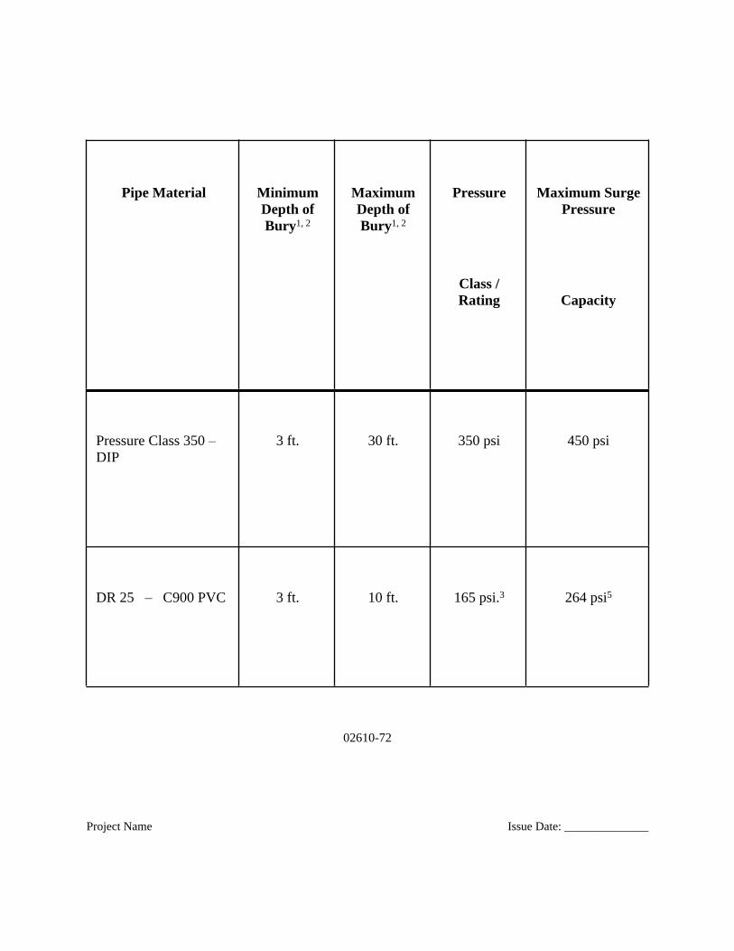
A. This pipe shall meet the requirements of AWWA C900-75 for Polyvinyl Chloride(PVC) Pressure Pipe. The pipe shall be PVC 1120 pipe with cast iron pipe equivalentODs. See Table 1 below for pipe material depth and pressure limitations.
02610-68
Project Name Issue Date: ______________
B. Provisions must be made for expansion and contraction at each joint with a rubberring. The bell shall consist of an integral wall section with a solid cross-sectionrubber ring which meets the laboratory performance of ASTM D3139. The bellsection shall be designed to be at least as strong as the pipe wall.
C. Standard laying lengths shall be 20 feet + for all sizes. At least 85 percent of the totalfootage of pipe of any class and size shall be furnished in standard lengths, theremaining 15% in random lengths. Random lengths shall not be less than 10 feetlong. Each standard and random length of pipe shall be tested to four times the classpressure. The integral bell shall be tested with the pipe.
D. Fittings for all lines 4 inches in diameter or larger shall be restrained ductile iron andin accordance with AWWA C153 and have a body thickness and radii of curvatureconforming to ANSI A21.10 or ANSI A21.53 for compact fittings.
02610-69
Project Name Issue Date: ______________
E. Fittings for all lines less than 4 inches in diameter shall be PVC gasketed push ontype or socket glue-type manufactured specifically for the pipe class being utilized.All socket-glue type connections shall be joined with PVC solvent cementconforming to ASTM D2564. Product and viscosity shall be as recommended by thepipe and fitting manufacturer to assure compatibility. Solvent cement joints shall bemade up in accordance with the requirements of ASTM D2855.
F. Appropriate restraint shall be provided for all fittings. Fittings shall be restrained withEBAA Iron Mega-Lugs, or equal. Pipe joints on either side of the fittings shall also berestrained to the distance required by the restrained joint calculations with theappropriate EBAA Iron Mega- Lug. The appropriate restraints are listed below:
1. Series 2000SV& 2000PV: MEGALUG Restraint for existing C900 PVC Pipe at DIP
2. Series 2800: MEGALUG Restraint Harness for C900
02610-70
Project Name Issue Date: ______________
3. Series 2200: MEGALUG Restraint for C900 at DIP Mechanical Joint fitting
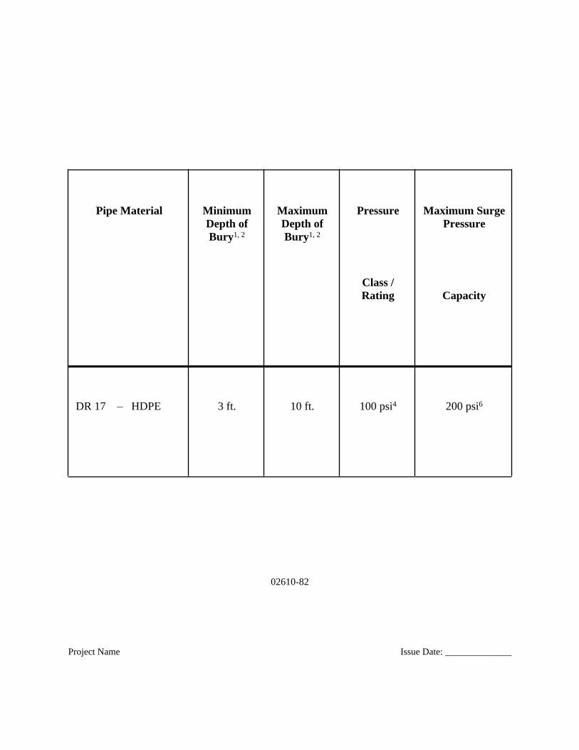
G. Pipe material depth and pressure limitations (Table 1)
02610-71
Project Name Issue Date: ______________
(THIS SPACE INTENTIONALLY LEFT BLANK)
TABLE -1 Pipe Material Depth and Pressure Limitations
02610-72
Project Name Issue Date: ______________
Pipe Material MinimumDepth ofBury1, 2
MaximumDepth ofBury1, 2
Pressure
Class /Rating
Maximum SurgePressure
Capacity
Pressure Class 350 – DIP
3 ft. 30 ft. 350 psi 450 psi
DR 25 – C900 PVC 3 ft. 10 ft. 165 psi.3 264 psi5

02610-73
Project Name Issue Date: ______________
DR 18 – C900 PVC 3 ft. 20 ft. 235 psi.3 376 psi5
DR 14 – C900 PVC 3 ft. 30 ft. 305 psi.3 488 psi5
Table Notes:
1. Depth of bury limitations are provided as a general rule. At the discretion of SD1, greater depths may be allowed provided special pipe bedding is provided. Under some combinations of pipe material, soil type and bedding conditions, maximum acceptable depths may be reduced. For all applications where depth of bury is greater than or equal to thirty (30) feet, DIP shall be used.
02610-74
Project Name Issue Date: ______________
2. Design ENGINEER shall consult appropriate references to ensure selected pipe material is suitable for each application. Such references may include the DIPRA Design of Ductile Iron Pipe brochure, Uni-Bell Handbook of PVC Pipe Design and Construction, PWEagle Technical Bulletins TB-D5 and TB-D8 (for PVC pipe), or Performance Pipe Bulletin PP 503 and PP 508 (for HDPE pipe) or other appropriate sources.
3. Total System Pressure (i.e. maximum working pressure plus any routine pressure surge) shall be less than the Pressure Class, as defined by AWWA C900-07 (values given in the above table are at 73.4˚F). “Maximum working pressure” is the maximum steady-state, sustained operating pressure applied to the pipe exclusive of transient pressures.
4. Maximum working pressure shall be less than the Pressure Class, and Total System Pressure (i.e. maximum working pressure plus any routine pressure surge) shall be less than 1.5 times the Pressure Class, as defined by AWWA C906-07 (values given in the above table are at 73.4˚F). “Maximum working pressure” is the maximum steady-state, sustained operating pressure applied to the pipe exclusive of transient pressures.
02610-75
Project Name Issue Date: ______________
5. For C900 PVC pipe, maximum working pressure plus occasional or “emergency” surges shall not be greater than the Maximum Surge Pressure Capacity (1.6 times thePressure Class of the pipe) as defined by AWWA C900(2007).
2.5 HIGH DENSITY POLYETHYLENE (HDPE) PIPE AND FITTINGS
A. Smooth Wall
1. Qualification of Manufacturers: Qualified manufacturers shall be firms
02610-76
Project Name Issue Date: ______________
regularly engaged in the manufacture of HDPE pipe and pipe fittings of the same size, type, and joint configuration specified, and whose products have been in satisfactory use for not less than five (5) years.
2. Heat Fusion Training/Certification: The CONTRACTOR shall ensure and certify that persons making heat fusion joints have received training in the manufacturer’s recommended procedure not more than 12 months prior to commencing construction.
a. An experienced, competent, and authorized field service representativeshall be provided by the pipe manufacturer to perform all pipemanufacturer’s field services specified herein. The field servicerepresentative’s minimum required experience qualifications shallinclude 5 years of practical knowledge and experience in making heatfusion joints and installing HDPE pipe.
b. All HDPE pipe shall be installed in accordance with the pipemanufacturer’s recommendations. The pipe manufacturer’s fieldservice representative shall visit the site and inspect, check, instruct,guide, and direct CONTRACTOR’s procedures for pipe handling andinstallation at the start of the pipe installation. The fusion pipemanufacturer’s field service representative shall coordinate hisservices with CONTRACTOR.
02610-77
Project Name Issue Date: ______________
c. Each joint shall be checked by CONTRACTOR as instructed by thepipe manufacturer’s field service representative to determine that thepipe is properly fused.
d. As requested, the pipe manufacturer’s field service representative shallfurnish to SD1, through ENGINEER, a written report certifying thatCONTRACTOR’s installation personnel have been properly instructedand have demonstrated the proper pipe handling, fusion, andinstallation procedures. The pipe manufacturer’s field servicerepresentative shall also furnish to SD1, through ENGINEER, awritten report of each site visit. The pipe manufacturer’s field servicerepresentative shall revisit the site as often as necessary until alltrouble is corrected and the pipeline installation and operation aresatisfactory in the opinion of the ENGINEER.
e. All costs for these services shall be included in the Contract Price.
3. Interchangeability of Pipe and Fittings: Within Contract limits, pipe and fittings from different approved manufacturers shall not be interchanged.
02610-78
Project Name Issue Date: ______________
4. HDPE shall be manufactured in accordance with ASTM F 714, Polyethylene (PE) Plastic Pipe (SDR-PR) Based on Outside Diameter, and shall be so marked. Each production lot of pipe shall be tested for (from material or pipe)melt index, density, percent carbon, (from pipe) dimensions and ring tensile strength.
5. Materials used for the manufacture of HDPE pipe and fittings shall be PE3408HDPE, meeting cell classification 345434C or 345434E per ASTM D 3350 and meeting Type III, Class B or Class C, Category 5, Grade P34 per ASTM D 1248; and shall be listed in the name of the pipe and fitting manufacturer in Plastics Pipe Institute (PPI) TR-4, Recommended Hydrostatic Strengths and Design Stresses for Thermoplastic Pipe and Fittings Compounds, with a standard grade rating of 1,600 psi at 73° F. The manufacturer shall certify
that the materials used to manufacture pipe and fittings meet those requirements.
6. Fabricated fittings shall be made by heat fusion joining specially machined shapes cut from pipe, polyethylene sheet stock, or molded fittings. Fabricatedfittings shall be rated for internal pressure service at least equal to the full service pressure rating of the mating pipe. Directional fittings 16-inch IPS and larger such as elbows, tee, etc., shall have a plain end inlet for butt fusion and flanged directional outlets.
02610-79
Project Name Issue Date: ______________
7. Molded fittings shall be manufactured in accordance with ASTM D 3261, Butt Heat Fusion Polyethylene (PE) Plastic Fittings for Polyethylene (PE ) Plastic Pipe and Tubing, and shall be so marked. Each production lot of molded fittings shall be subjected to the test required under ASTM D 3261.
8. Flange adapters shall be made with sufficient through-bore length to be clamped in a butt fusion joining machine without the use of a stub-end holder.The sealing surface of the flange adapter shall be machined with a series of small V-shaped grooves to provide gasketless sealing, or to restrain the gasketagainst blow-out.
9. Flange adapters shall be fitted with back-up rings pressure rated equal to or greater than the mating pipe. The back-up ring bore shall be chamfered or radiused to provide clearance to the flange adapter radius. Flange bolts and nuts shall be Grade 2 or higher.
10. Joints between HDPE pipes and between HDPE fittings and pipes shall be fusion bonded as described in Section 3.5.
02610-80
Project Name Issue Date: ______________
11. The exterior of the HDPE pipe shall be color coded and striped in a way to identify the difference in pipe service, size and application.
12. HDPE pipe shall be black.
13. All piping used for horizontal directional drilling shall be permanently striped.
14. Internal 316 stainless steel stiffeners as manufactured by JCM Industries, Inc.,or approved equal shall be used at all locations where external connectors or restraint clamps are installed. MJ adapters as manufactured by Central Plastics Company or equal, with creation of positive restraint to the pipe from heat fusion of the adapter to the pipe, and creation of positive restraint at the connection through bolting of the backup ring to the MJ valve or fitting, can be used in lieu of the JCM internal stainless steel stiffeners and external restraint clamps.
15. Except as noted in item 14 above, all mechanical connections shall be
02610-81
Project Name Issue Date: ______________
stiffened and restrained. Restraints shall be as manufactured by JCM Industries, Inc., or approved equal.
16. External restraint clamps utilized for transition from ductile iron pipe to polyethylene pipe shall be as manufactured by JCM Industries, Inc., or approved equal. Restraints must be compatible with stiffeners and pipe. JCMrestraints shall not be used with HDPE pipe in locations where test pressures will exceed 150 psi. In locations where HDPE pipe will have test pressures exceeding 150 psi, provide an MJ adapter as described in item 14 above.
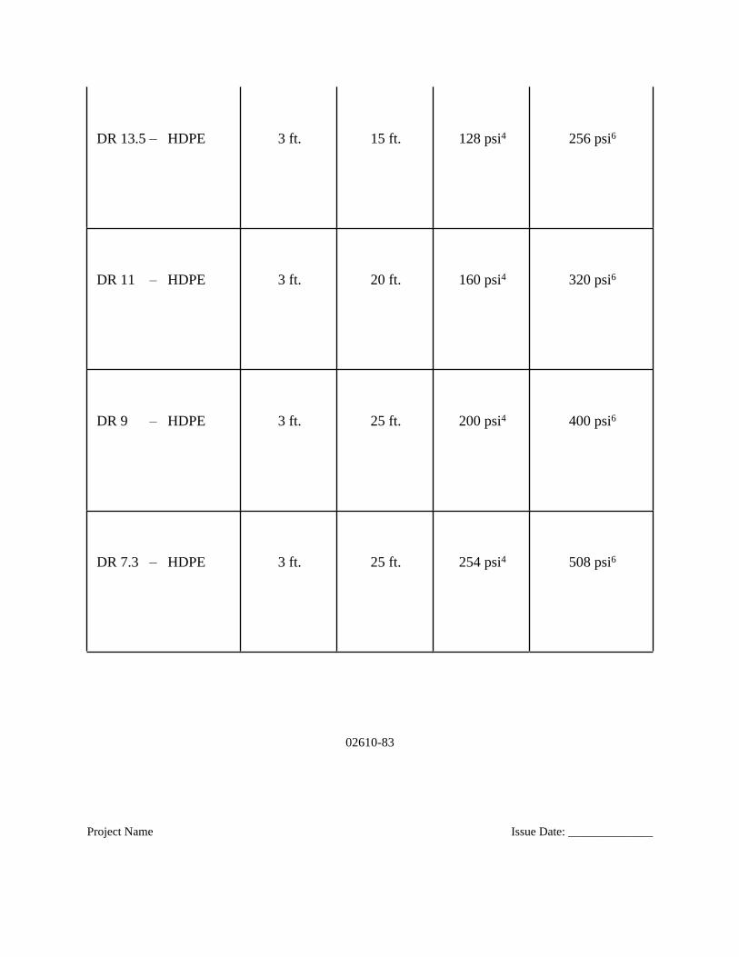
17. The Dimension Ratios (DR’s) are shown on the table (Table 2) below:
Table 2 – Pipe Material Depth and Pressure Limitations
02610-82
Project Name Issue Date: ______________
Pipe Material MinimumDepth ofBury1, 2
MaximumDepth ofBury1, 2
Pressure
Class /Rating
Maximum SurgePressure
Capacity
DR 17 – HDPE 3 ft. 10 ft. 100 psi4 200 psi6
02610-83
Project Name Issue Date: ______________
DR 13.5 – HDPE 3 ft. 15 ft. 128 psi4 256 psi6
DR 11 – HDPE 3 ft. 20 ft. 160 psi4 320 psi6
DR 9 – HDPE 3 ft. 25 ft. 200 psi4 400 psi6
DR 7.3 – HDPE 3 ft. 25 ft. 254 psi4 508 psi6
02610-84
Project Name Issue Date: ______________
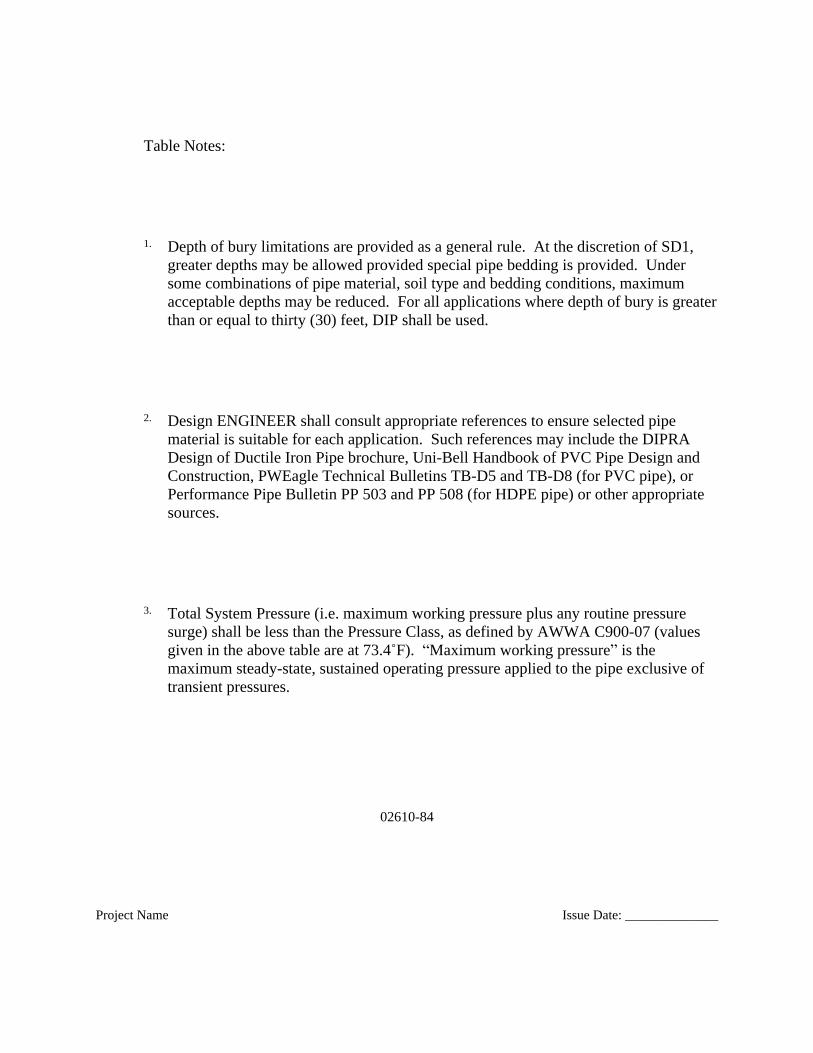
Table Notes:
1. Depth of bury limitations are provided as a general rule. At the discretion of SD1, greater depths may be allowed provided special pipe bedding is provided. Under some combinations of pipe material, soil type and bedding conditions, maximum acceptable depths may be reduced. For all applications where depth of bury is greaterthan or equal to thirty (30) feet, DIP shall be used.
2. Design ENGINEER shall consult appropriate references to ensure selected pipe material is suitable for each application. Such references may include the DIPRA Design of Ductile Iron Pipe brochure, Uni-Bell Handbook of PVC Pipe Design and Construction, PWEagle Technical Bulletins TB-D5 and TB-D8 (for PVC pipe), or Performance Pipe Bulletin PP 503 and PP 508 (for HDPE pipe) or other appropriate sources.
3. Total System Pressure (i.e. maximum working pressure plus any routine pressure surge) shall be less than the Pressure Class, as defined by AWWA C900-07 (values given in the above table are at 73.4˚F). “Maximum working pressure” is the maximum steady-state, sustained operating pressure applied to the pipe exclusive of transient pressures.
02610-85
Project Name Issue Date: ______________
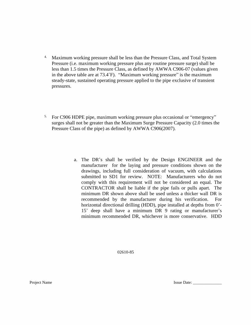
4. Maximum working pressure shall be less than the Pressure Class, and Total System Pressure (i.e. maximum working pressure plus any routine pressure surge) shall be less than 1.5 times the Pressure Class, as defined by AWWA C906-07 (values given in the above table are at 73.4˚F). “Maximum working pressure” is the maximum steady-state, sustained operating pressure applied to the pipe exclusive of transient pressures.
5. For C906 HDPE pipe, maximum working pressure plus occasional or “emergency” surges shall not be greater than the Maximum Surge Pressure Capacity (2.0 times the Pressure Class of the pipe) as defined by AWWA C906(2007).
a. The DR’s shall be verified by the Design ENGINEER and themanufacturer for the laying and pressure conditions shown on thedrawings, including full consideration of vacuum, with calculationssubmitted to SD1 for review. NOTE: Manufacturers who do notcomply with this requirement will not be considered an equal. TheCONTRACTOR shall be liable if the pipe fails or pulls apart. Theminimum DR shown above shall be used unless a thicker wall DR isrecommended by the manufacturer during his verification. Forhorizontal directional drilling (HDD), pipe installed at depths from 0’-15’ deep shall have a minimum DR 9 rating or manufacturer’sminimum recommended DR, whichever is more conservative. HDD

02610-86
Project Name Issue Date: ______________
pipe installed at depths greater than 15’ shall also have a minimum DR9 rating or manufacturer’s minimum recommended DR, whichever ismore conservative. CONTRACTOR shall note that depending onthe wall thickness of the pipe to be furnished, an increase in pipesize may be required to provide comparable internal diameter toductile iron pipe.
18. Mechanical joint ductile iron fittings for DIP sized HDPE pipe meeting all requirements of ANSI A211.11 (AWWA C111) may be used in lieu of HDPE pipe fittings. Restraints shall be Sur-Grip as manufactured by JCM Industries,Inc., or approved equal.
19. Nuts, bolts, and tie -rods used on buried pressure pipe and fittings shall be lowalloy steel T- bolts with Zinc anode caps for all T-bolts and rods. The entire installation shall be wrapped in two layers of polyethylene encasement. Nuts, bolts and stiffener plates which will be in contact with sewage shall be stainless steel Type 316.
20. HDPE pipe shall have OD of ductile iron pipe.
21. HDPE pipe shall be as manufactured by CP Performance Pipe, or equal.
02610-87
Project Name Issue Date: ______________
B. Corrugated HDPE (For Storm Sewer Only)
1. Corrugated polyethylene pipe with an integrally formed smooth interior shallmeet the requirements of AASHTO M 294, Standard Specification forCorrugated Polyethylene Pipe, 12 to 36 inch diameter, for Type S pipe. SD1will consider the use of large diameter HDPE on a case-by-case basis;approval shall be at SD1's discretion
2. HDPE pipe shall be joined using an inline bell (IB) & spigot joint or fittingmeeting AASHTO M294 or ASTM F2306. The joint or fitting shall be soil-tight and gaskets shall meet the requirements of ASTM F477.
02610-88
Project Name Issue Date: ______________
2.6 FIBERGLASS REINFORCED POLYMER MORTAR (FIBERGLASS) PIPE AND
FITTINGS (GRAVITY LINES)
A. Fiberglass reinforced polymer mortar (fiberglass) pipe and fittings for gravity sewersshall conform to the requirements of ASTM D-3262, current approval, “StandardSpecification for ‘Fiberglass’ (Glass-Fiber-Reinforced Thermosetting Resin) SewerPipe.”
B. Materials
02610-89
Project Name Issue Date: ______________
1. Resin Systems: The manufacturer shall use only polyester resin systems witha proven history of performance in this particular application. The historicaldata shall have been acquired from a composite material of similarconstruction and composition as the proposed product.
2. Glass Reinforcements: Chopped glass reinforcement fibers used tomanufacture the components shall be of highest quality commercial grade E-glass filaments with binder and sizing compatible with impregnating resins.Continuous circumferential glass reinforcement fibers, where utilized, shall beof grade ECR-glass with binder and sizing compatible with impregnatingresins.
3. Silica Sand: Sand shall be a minimum of 98% silica with a maximummoisture content of 0.2%.
4. Additives: Resin additives, such as curing agents, pigments, dyes, fillers,thixotropic agents, etc., when used, shall not detrimentally affect theperformance of the product.
02610-90
Project Name Issue Date: ______________
5. Elastomeric Gaskets: Gaskets shall be supplied by qualified gasketmanufacturers and be suitable for the service intended.
C. Manufacture and Construction
1. Pipes: Manufacture pipe by a process that will result in a dense, non-porous,corrosion-resistant, consistent composite structure.
2. Joints: Unless otherwise specified, the pipe shall be field connected withfiberglass couplings that utilize elastomeric EPDM or REKA sealing gasketsas the sole means to maintain joint watertightness. The joints shall meet theperformance requirements of ASTM D4161. Additionally, the joints shall be
02610-91
Project Name Issue Date: ______________
rated to a pressure of 80% of -14.7 psi as installed. Joints at tie-ins, whenneeded may utilize fiberglass, gasket-sealed closure couplings.
3. Fittings: Flanges, elbows, reducers, tees, wyes, laterals and other fittings shallbe capable of withstanding all operating conditions when installed. They mustbe made and delivered from Manufaturer.All fittings and couplings shall bepressure rated for a minimum of 50 psi.
4. End Coating: Protective spigot end resin coating shall be applied at the time ofmanufacture. CONTRACTOR shall similarly coat the ends of all field cutpipes if the wall of the pipe is completely de-aerated during the productionprocess and glass and sand are not impregnated with 100% pure resin to forma wall that cannot be penetrated by water.
5. Fiberglass pipe shall be as manufactured by: Hobas Pipe USA, Inc., orapproved equal.
6. For bury depths greater than 20 feet, CONTRACTOR shall comply withspecial trench construction requirements recommended by the manufacturer.

02610-92
Project Name Issue Date: ______________
D. Dimensions:
1. Diameters: The actual outside diameter of the pipe barrel shall be inaccordance with ASTM D3262. The internal diameters of all pipes shall be asspecified on the Contract Drawings for each pipe diameter.
2. Lengths: Pipe shall be supplied in nominal lengths of 20 feet. Actual layinglength shall be nominal +1, -4 inches. At least 90% of the total footage ofeach size and class of pipe, excluding special order lengths, shall be furnishedin nominal length sections.
3. Wall Thickness: The minimum wall thickness shall be the required designthickness for the laying conditions. Manufacturer shall provide information inwriting to SD1 per the submittal requirements.
02610-93
Project Name Issue Date: ______________
4. End Squareness: Pipe ends shall be square to the pipe axis with a maximumtolerance of 1/4”.
E. Testing:
1. Pipes: Pipes shall be manufactured and tested in accordance with ASTMD3262.
2. Joints: Joints shall meet the requirements of ASTM D4161.
3. Stiffness: As tested in accordance with ASTM D2412. Any fiberglass pipe
02610-94
Project Name Issue Date: ______________
run that exceeds 20 feet, but less than 30 feet, in depth to invert anywherealong the run length from one manhole or structure to a second manhole orstructure shall be a minimum stiffness of 72 psi for the entire run.
F. Customer Inspection
1. SD1 or other designated representative shall be entitled to inspect pipes at thefactory or witness the pipe manufacturing.
2. Manufacturers Notification to Customer: Should SD1 request to see specificpipes during any phase of the manufacturing process, the manufacture mustprovide SD1 with adequate advance notice of when and where the productionof those pipes will take place.
02610-95
Project Name Issue Date: ______________
G. Packaging, Handling, and Shipping shall be done in accordance with themanufacturer’s instructions.
2.7 REINFORCED CONCRETE PIPE (RCP)
A. Circular reinforced concrete pipe shall meet the requirements of ASTM C 76,Standard Specification for Reinforced Concrete Culvert, Storm Drain and Storm Pipe.Elliptical reinforced concrete pipe shall meet the requirements of ASTM C 507,Standard Specification for Reinforced Concrete Elliptical Culvert, Storm Drain andSewer Pipe.
02610-96
Project Name Issue Date: ______________
B. Rubber and plastic joints, or approved equal, shall be the jointing method for RCPand shall meet the requirements of AASHTO M 315 / ASTM C 443. Other methodsof joining RCP will only be allowed upon explicit approval from SD1.
C. When RCP is used under pavement or driveways, a minimum of Class III RCP shallbe required or higher class as noted on drawings.
02610-97
Project Name Issue Date: ______________
2.8 CORRUGATED METAL PIPE (CMP) (FOR STORM SEWERS ONLY)
A. Corrugated steel pipe shall meet the requirements of AASHTO M36. Corrosionprotection shall be provided through an aluminized coating conforming to AASHTOM274. Aluminum alloy spiral pipe shall meet the requirements of AASHTO M196.
02610-98
Project Name Issue Date: ______________
Coating materials shall be evaluated on a per project basis. Asphalt coatings shall notbe permitted for corrugated metal pipe.
B. Joints for CMP shall be made using coupling bands and gaskets meeting therequirements of AASHTO M 36 and AASHTO M 274.
2.9 HIGH-PERFORMANCE POLYPROPYLENE PIPE
02610-99
Project Name Issue Date: ______________
A. For sanitary sewer applications, high-performance polypropylene pipe shall meet therequirements of ASTM F2736 for 12”-30” pipe, and ASTM F2764 for 30”-60” pipe.
B. For sanitary sewer applications, pipe shall be joined with an extended reinforcedintegral bell & double gasketed spigot to provide a watertight seal in accordance withASTM D3212.
C. For storm sewer application, high-performance polypropylene pipe shall meet therequirements of ASTM F2881 and AASHTO M330.
02610-100
Project Name Issue Date: ______________
D. For storm sewer application, pipe shall be joined with a extended reinforced integralbell & gasketed spigot in accordance with ASTM D32212.2.9
2.10 TRACER WIRE
A. All pressure pipe shall have marking tape 6” wide. Marking tape for the manholeshall be green with the words “Sanitary Sewer” installed approximately twelve (12)inches above the pipe and shall continue for the length of the pipe installation.
02610-101
Project Name Issue Date: ______________
B. All pipe for sanitary force mains shall be installed with a twelve (12) gauge solidcopper (PVC coated) tracing wire taped to the top of the pipe every five (5) feet. Notracing wire length shall exceed fifteen hundred (1500) feet between air release valvesand/or discharge manhole, where system becomes gravity, without terminating in acurb stop box marked with “Sewer”. Tracing wire must run continuously through airrelease valves and made accessible from ground level. Sanitary force mains that endin a discharge manhole, at which point system becomes gravity, shall terminatetracing wire in a curb stop box next to the discharge manhole. Curb stop boxes shallnot be located in pavement areas. Splices in the tracing wire shall be kept to aminimum and approved by SD1. If splices are required, they shall be made withcopper split bolt (Ilsco #1K-8 or approved equal) and taped with electrical tape.Tracer wire shall be tested to confirm it is functioning properly after installation.
2.11 PIPE COUPLINGS

02610-102
Project Name Issue Date: ______________
A. For new pipe installation, transition between two differing pipe materials must bedone at manhole terminations, unless another method is approved by SD1. Forconnections to existing sewers of differing pipe material, Frenco “flexible couplings”
or equal shall be used.
B. For any other field cut connection, the pipe couplings shall be of a gasketed, sleeve-type with diameter to properly fit the pipe. Each coupling shall consist of one (1)stainless steel middle ring, of thickness and length specified, two (2) stainless steelfollowers, two (2) rubber-compounded wedge section gaskets and sufficient track-head steel bolts to properly compress the gaskets. The couplings shall be assembledon the job in a manner to insure permanently tight joints under all reasonableconditions of expansion, contraction, shifting and settlement, unavoidable variationsin trench gradient, etc. The coupling shall be Dresser, Style 38, as manufactured byDresser Manufacturing Division, Bradford, PA, or equal.
02610-103
Project Name Issue Date: ______________
2.12 WYE BRANCH FITTINGS AND LATERALS FOR NEW CONSTRUCTION
A. Tee or wye branch fittings shall be used for household or service connection lines tothe sewer collector line. The fittings shall meet the requirements of the mainline pipematerials as specified herein. The wyes and tees shall be located as shown on theContract Drawings or as directed by the ENGINEER. The wyes and tees shall bepositioned as to require the least number of fittings per lateral connection. Regularwye connections shall be in accordance with Standard Drawing No. 120. Stack wyeconnections shall include vertical piping, elbows, wye, and concrete encasement inaccordance with Standard Drawing No. 108. If a single sweep tee connection is used,the sweep must be in the direction of sanitary sewer main

02610-104
Project Name Issue Date: ______________
B. Inserta Tee pipe fittings are permitted as an alternate lateral tap connection in lieu ofwye fittings when main pipe nominal diameter is greater than 12” or on a case by casebasis for new construction. Inserta Tee type shall be compatible for the pipe type betapped. Contractor shall be responsible for supplying the proper Tee. Install InsertaTees using procedures and equipment as referenced in the manufacturer’s writteninstallation instructions and in accordance with standard drawing 102.
C. Lateral extensions shall be installed from the end of the regular or stack wyeconnection to the limit of easement or public right-of-way in accordance withStandard Drawing No. 120.
2.13 CONNECTIONS TO EXISTING SEWERS
02610-105
Project Name Issue Date: ______________
A. Connections to existing public sewers shall be made at the nearest wye or teeavailable on the public sewer. Connections to existing sewers where wyes or tees arenot available shall be made by one of the following methods:
1. Install a wye or tee branch fitting per the manufacturer’s recommendations oran approved method by SD1.
2. Inserta Tee Pipe Fittings: Install Inserta Tees using procedures and equipmentas referenced in the manufacturer’s written installation instructions and inaccordance with standard drawings 102.
02610-106
Project Name Issue Date: ______________
3. Tapping Saddles: Tapping saddles shall only be used with the explicitapproval of SD1 on a case by case basis. If approved install permanufacturer’s recommendations.
2.14 STORM LATERAL CONNECTIONS
A. Roof downspouts, footing or foundation drains, and sump pumps shall discharge inaccordance with the local governing subdivision regulations. All storm lateralconnections (downspouts, footing or foundation drains, sump pumps, etc) to the stormsewer shall be prohibited unless explicitly reviewed and approved by SD1 due to

02610-107
Project Name Issue Date: ______________
uncommon circumstances (i.e. inadequate discharge distances from foundations,narrow side yards, etc).
PART 3 – EXECUTION
3.1 GENERAL
02610-108
Project Name Issue Date: ______________
A. Contractor shall refer to Section 02220 for all excavation, trench preparation, beddingand backfill requirements.
B. After being delivered alongside the trench, the pipe, fittings, and specials shall becarefully examined for cracks, soundness, or damage, or other defects whilesuspended above the trench before installation. No piece of pipe or fitting which isknown to be defective shall be laid or placed in the lines. If any defective pipe orfitting shall be discovered after the pipe is laid, it shall be removed and replaced witha satisfactory pipe or fitting without additional charge. Before each piece of pipe islowered into the trench, it shall be thoroughly cleaned out. Each piece of pipe shallbe lowered safely and separately in the trench. In case a length of pipe is cut to fit ina line, it shall be so cut as to leave a smooth end at right angles to the longitudinalaxis of the pipe.
C. The bell and spigot of the joint shall be thoroughly wire brushed and cleaned of dirt
02610-109
Project Name Issue Date: ______________
and foreign matter immediately prior to jointing. The contact surfaces shall be coatedwith the lubricant, primer or adhesive recommended by the manufacturer, and thenthe pipe shall be pushed together until the joint snaps distinctly in place. The pushingtogether of the pipe may be done by hand or by the use of a bar.
D. Place pipe to the grades and alignment indicated, runs of pipe between manholes shallbe within 95% of the slope shown on the plans unless otherwise directed by theENGINEER. Remove and relay pipes that are not laid correctly. Slope pipinguniformly between elevations shown.
E. Trenches shall be kept dry during pipe laying. Before pipe laying is started, all waterthat may have collected in the trench shall be removed. Ensure that ground waterlevel in trench is at least 12 inches below bottom of pipe before laying piping. Do notlay pipe in water. Maintain dry trench conditions until jointing and backfilling arecomplete and protect and keep clean water pipe interiors, fittings and valves.
02610-110
Project Name Issue Date: ______________
F. All pipe shall be laid starting at the lowest point and proceed towards the higherelevations, unless otherwise approved by ENGINEER. Place bell and spigot pipe sothat bells face the direction of laying, unless otherwise approved by ENGINEER.
G. When laying of the pipe is stopped, the end of the pipe shall be securely plugged orcapped. Plugging shall prevent the entry of animals, liquids, or persons into the pipeor the entrance or insertion of deleterious material.
1. Install standard plugs into all bells at dead ends, tees or crosses. Cap allspigot ends.

02610-111
Project Name Issue Date: ______________
2. Fully secure and block all plugs and caps installed for pressure testing towithstand the specified test pressure.
3. Where plugging is required for phasing of the Work or for subsequentconnection of piping, install watertight, permanent type plugs.
H. As required by SD1, pipe manufacturer for each pipe type used shall be present andinstruct CONTRACTOR on proper installation technique per shop drawings andmanufacturer’s recommended procedures prior to the start of the Work.
02610-112
Project Name Issue Date: ______________
I. Install piping as shown, specified and as recommended by the manufacturer. If thereis a conflict between manufacturer’s recommendations and the Drawings orSpecifications, request instructions from SD1 before proceeding.
J. Deflections at joints shall not exceed 75 percent of the amount allowed by the pipemanufacturer.
K. Field cut pipe, where required, with a machine specially designed for cutting piping.Make cuts carefully, without damage to pipe or lining, and with a smooth end at rightangles to the axis of pipe. Cut ends on push-on joint shall be tapered and sharp edgesfiled off smooth. Flame cutting will not be allowed.
02610-113
Project Name Issue Date: ______________
L. Touch up protective coatings in a satisfactory manner prior to backfilling. See pipematerial section for specific requirements.
M. Place concrete pipe containing elliptical reinforcement with the minor axis of thereinforcement in a vertical position.
02610-114
Project Name Issue Date: ______________
N. Laying Pipe and Service Laterals
1. Conform to manufacturer's instructions and requirements of the standardslisted below, where applicable:
a. Ductile Iron Pipe: AWWA C600, AWWA C105.
b. Concrete Pipe: AWWA M9, Concrete Pipe Handbook.
c. Thermoplastic Pipe: ASTM D 2774.
d. ASCE Manual of Practice No. 37.
02610-115
Project Name Issue Date: ______________
3.2 PIPE INSTALLATION – GENERAL
A. Excavation for Pipeline Trenches: Refer to Section 02220. Trenches in which pipesare to be laid shall be excavated to the depths shown on the Drawings or as specifiedby the ENGINEER. Minimum cover for all pipelines shall be 36 inches minimumcover as measured from top of pipe, unless otherwise shown on the Drawings orapproved by the ENGINEER. Trench excavations maybe inspected by ENGINEERprior to laying pipe. Notify SD1 48 hours in advance of all excavating, bedding andpipe laying operations.
02610-116
Project Name Issue Date: ______________
B. Jointing: The types of joints described herein shall be made in accordance with themanufacturer’s recommendations.
C. Separation of Sanitary Sewers and Potable Water Pipe Lines:
1. Horizontal Separation:
a. Wherever possible, existing and proposed potable water mains andservice lines, and sanitary and storm sewers and service lines shall beseparated horizontally by a clear distance of not less than 10 feet.
02610-117
Project Name Issue Date: ______________
b. If local conditions preclude a clear horizontal separation of not less 10feet, the installation will be permitted provided the potable water mainis in a separate trench or on an undistributed earth shelf located on oneside of the sewer and at an elevation so the bottom of the potable watermain is at least 18 inches above the top of the sewer.
c. Exception:
1) Where it is not possible to provide the minimum horizontalseparation described above, the potable water main must beconstructed of cement lined ductile iron slip-on or mechanicaljoint pipe complying with the public water supply designstandards of the governing agency. Sewer must be constructed ofepoxy lined ductile iron slip-on or mechanical joint pipecomplying with SD1’s requirements.
2. Crossings:
02610-118
Project Name Issue Date: ______________
a. Provide a minimum vertical distance of 18 inches between the outsidesof pipes.
b. Center one full length section of potable water main over the sewer sothat the sewer joints will be equidistant from the potable water mainjoints.
c. Provide adequate structural support where a potable water maincrosses under a sewer to maintain line and grade.
d. Exceptions:
1) See requirements in paragraph 3.2.C.1.c.(1) above.
02610-119
Project Name Issue Date: ______________
2) Concrete encase as directed by SD1.
D. Permanent slope anchors shall be installed on all pipe with slopes over twenty (20)percent. See the SD1’s standard detail for Concrete Anchor Block. Consult with SD1on spacing of the anchors.
E. Reaction Anchorage (Pressure Pipe Only):
1. All tees, Y-branches, bends deflecting 11-1/4 degrees or more, and plugs
02610-120
Project Name Issue Date: ______________
which are installed in buried piping shall be provided with proprietaryrestrained joint systems for preventing movement of the pipe and jointscaused by the internal test pressure.
F. Thrust Restraint
1. Provide thrust restraint on pressure piping systems where shown andspecified.
2. Thrust restraint for DIP shall be accomplished by means of restrained pipejoints.
3. Thrust restraints shall be designed for the axial thrust exerted by the systemdesign pressures as specified by the Design ENGINEER.
02610-121
Project Name Issue Date: ______________
G. Dewatering and Ground Water
1. Discharging of sediment laden groundwater or rainwater from excavations directly to watercourses or storm sewers is prohibited. Failure of the CONTRACTOR to comply with the requirements of this specification may result in SD1 issuing a stop work order or non-approval of pay estimates until the CONTRACTOR puts measures in place to comply with this specification. All costs associated with the stop work or non-approval of pay estimates shall be at the CONTRACTOR’s sole expense.
2. Pipe trenches and excavations for appurtenances shall be kept free from water during trench bottom preparation, pipe laying and jointing, pipe embedment and building of appurtenances in an adequate and acceptable manner.
3. Where the trench or excavation bottom is mucky or otherwise unstable
02610-122
Project Name Issue Date: ______________
because of ground water, or where the ground water elevation is above the bottom of the trench or excavation, the ground water shall be lowered by means acceptable to the ENGINEER to the extent necessary to keep the trenchor excavation free from water while the trench or excavation is in progress. The discharge of ground water from the trench or excavation area shall be by the methods specified below to natural drainage channels, gutters, drains, or storm sewers which will conduct the water away from the trench or excavation area. Means of diverting any surface water away from the trench or excavation area shall be taken and surface water prevented from entering the trench or excavation area.
4. Dewatering equipment shall be provided to remove and dispose of all surface water and groundwater entering excavations, trenches, or other parts of the work. Each excavation shall be kept dry during sub grade preparation and continually thereafter until the structure to be built, or the pipe to be installed therein, is com-pleted to the extent that no damage from hydrostatic pressure, flo-tation, or other cause will result.
5. All excavations for concrete structures or trenches which extend down to or below groundwater shall be dewatered by lowering and keeping the groundwater level beneath such excavations a minimum of 6 inches or more below the bottom of the excavation.
6. Surface water shall be diverted or otherwise prevented from entering excavations or trenches to the greatest extent possible without causing damageto adjacent property.
02610-123
Project Name Issue Date: ______________
7. Groundwater and rainwater removed during dewatering shall be discharged onto undisturbed ground where vegetative cover exists or through sediment and erosion controls and allowed to flow overland to filter out any sediments before discharging to any drain, storm sewer, or watercourse specified above. No such flows are permitted onto exposed soils, stream banks, or other areas subject to erosion.
8. Where overland flow on existing undisturbed ground is not sufficient to adequately remove all sediment from dewatering operations prior to dischargeto any drain, storm sewer, or watercourse, or other erosion control measureacceptable to SD1 or ENGINEER shall be used to remove the sediment from the water prior to discharge. The method of discharging ground water or rain water from the trench or excavation area shall be such as to not create any erosion of existing ground.
9. All discharge locations shall be approved prior to construction by the ENGINEER and SD1.
02610-124
Project Name Issue Date: ______________
10. CONTRACTOR shall take measures to prevent damage to properties, structures, sewers, and other utility installations and other work.
11. CONTRACTOR shall repair all damage, disruption, or interference resulting directly or indirectly from groundwater control system operations at no additional cost to SD1.
12. The CONTRACTOR shall maintain the components of the dewatering systemand surface water erosion and sediment controls within the project site. Deficiencies identified during visual inspection by SD1, SD1’srepresentatives, or the governing regulatory authority shall be remedied by theCONTRACTOR at no additional cost to SD1.
13. Dewatering system components shall be located where they will not interfere with construction activities adjacent to the work area.
14. The CONTRACTOR shall be responsible for the condition of any pipe or
02610-125
Project Name Issue Date: ______________
conduit which he may use for drainage purposes, and all such pipe or conduit shall be left clean and free of sediment.
H. Ground Water Barriers:
1. Where specified, continuity of bedding material shall be interrupted by low permeability groundwater barriers to impede passage of water through the bedding. Groundwater barriers for all pipelines shall be soil plugs of 3 feet in thickness, extending the full depth and width of the pipe bedding material in the trench, and spaced not more than 400 feet apart. The soil plugs shall be constructed from soil meeting ASTM D2487 classification GC, SC, CL, or ML, and compacted to 95 percent of maximum density at or near the optimummoisture content (ASTM D698).
02610-126
Project Name Issue Date: ______________
I. Pipe Encasements:
1. Concrete Encasement
a. Wherever pipe encasement is called for on the plans or ordered in bySD1, the CONTRACTOR shall construct the encasement as shown onthe drawings or in accordance with SD1’s standard drawings.
b. Support the pipe sections on solid concrete blocks, being sure to keepthe pipe sections on line and grade and then pour concrete, completelyunder each section, along each side and up to a point at least twelve(12) inches above the top of each section, making sure that all voids
02610-127
Project Name Issue Date: ______________
are filled. In lieu of blocks, the CONTRACTOR may use a bed ofconcrete, to initially support the pipe sections.
c. The minimum dimension of concrete under the pipe sections shall besix (6) inches and on each side of the sections shall be twelve (12)inches. This encasement shall be reinforced around the top and sides ofthe pipe as shown on the Contract Drawings for creek crossings andother locations. If the trench walls are nearly vertical from the bottomof the trench up to a point to which the encasement is to be poured,forms for forming the encasement may be omitted and the concretepoured to and against the trench walls. Where trench walls are notnearly vertical, proper forms shall be set for forming the encasement,unless otherwise called for by SD1. The space between the trenchwalls and any formed encasement shall be filled and compacted withapproved pipe bedding or backfilling material.
d. Care shall be taken to assure that the pipe sections remain on line andgrade during the placing of concrete and that the joints are notdisturbed. Backfill shall not be placed for a minimum of six (6) hoursafter encasement is completed, unless otherwise approved by SD1.
e. Exercise care to avoid flotation when installing pipe in cast-in-placeconcrete.
02610-128
Project Name Issue Date: ______________
2. Casing Pipe
a. Whenever casing pipe is called for on the plans, the CONTRACTORshall install a casing pipe of the size and of the material called for onthe plans by means of jacking, boring, or trenching.
b. When the casing pipe is to be installed under a highway or railroad,and at other locations specifically designated on the Drawings, themethod of installation shall be jacking or boring as specified in Section02400, unless trenching is specifically allowed.
1) For force mains inside casing pipe all pipe joints shall berestrained joint connections. Casing spacers shall be used tocenter the pipe in the casing. The annular space between theforce main and casing pipe shall be completely filled with 500psi or higher compressive strength grout.
02610-129
Project Name Issue Date: ______________
2) For gravity pipe inside casing pipe, casing spacers shall be usedto center the pipe within the casing. The annular space does nothave to be filled.
c. Casing Spacers- Include in casing pipe. Centered/Restrained Casingspacers shall be installed to position the carrier pipe within the centerof the casing pipe. The required spacing and installation shall be perthe manufacturer’s recommendation, except that for PVC carrier pipe,a minimum of 3 spacers shall be installed on each length of pipe with amaximum 6 feet spacing between spacers. All spacers shall be 316stainless steel as manufactured by Cascade Waterworks MFG Co.,Advance Products and Systems (APS) or other approved equal.Casing spacers shall also be provided with height field-adjustmentcapability for installation of gravity sewer on a constant slope.
d. Casing pipe end seals shall be installed at each end of the casing pipeand shall consist of a proper sized rubber seal and attached to thecarrier and casing pipe with stainless steel bands per the manufacturersrecommendation. Casing pipe end seals shall be manufactured byCascade Waterworks MFG Co., Advanced Products and Systems(APS) or other approved equal.
02610-130
Project Name Issue Date: ______________
J. Work Affecting Existing Piping
1. Location of Existing Piping:
a. Locations of existing piping shown should be considered approximate.
b. CONTRACTOR shall determine the true location of existing piping towhich connections are to be made, and location of other facilitieswhich could be disturbed during earthwork operations, or which maybe affected by CONTRACTOR'S Work in any way.
02610-131
Project Name Issue Date: ______________
c. Conform to applicable requirements of Division 1 pertaining to cuttingand patching, and connections to existing facilities.
2. Taking Existing Pipelines Out of Service:
a. Do not take pipelines out of service unless specifically noted on theDrawings, or approved by SD1.
3. Work on Existing Pipelines:
a. Cut or tap pipes as shown or required with machines specificallydesigned for this work.
02610-132
Project Name Issue Date: ______________
b. Install temporary plugs to prevent entry of mud, dirt, water and debris.
c. Provide all necessary adapters, fittings, pipe and appurtenancesrequired to complete the Work.
K. Install service laterals per SD1’s standard details and per the requirements specifiedin this specification,.
L. Bedding and backfilling of pipeline trenches shall be in accordance with the
02610-133
Project Name Issue Date: ______________
requirements set forth in Section 02220 and as shown on SD1’s trench compactiondetail.
M. Before final acceptance, the CONTRACTOR will be required to level all trenches orto bring the trench up to grade. The CONTRACTOR shall also remove fromroadways, rights-of-way and/or private property all excess earth or other materialsresulting from construction.
3.3 DUCTILE IRON PIPE INSTALLATION REQUIREMENTS
A. Jointing Pipe:
02610-134
Project Name Issue Date: ______________
1. Ductile Iron Mechanical Joint Pipe:
a. Wipe clean the socket, plain end and adjacent areas immediatelybefore making joint. Make certain that cut ends are tapered and sharpedges are filed off smooth.
b. Lubricate the plain ends and gasket with soapy water or an approvedpipe lubricant, in accordance with AWWA C111, just prior to slippingthe gasket onto the plain end of the joint assembly.
c. Place the gland on the plain end with the lip extension toward the plainend, followed by the gasket with the narrow edge of the gasket towardthe plain end.
02610-135
Project Name Issue Date: ______________
d. Insert the pipe into the socket and press the gasket firmly and evenlyinto the gasket recess. Keep the joint straight during assembly.
e. Push gland toward socket and center it around pipe with the gland lipagainst the gasket.
f. Insert bolts and hand tighten nuts.
g. Make deflection after joint assembly, if required, but prior totightening bolts. Alternately tighten bolts 180 degrees apart to seat thegasket evenly. The bolt torque shall be as follows:
Pipe Size Bolt Size Range of Torque
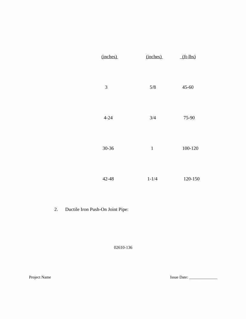
02610-136
Project Name Issue Date: ______________
(inches) (inches) (ft-lbs)
3 5/8 45-60
4-24 3/4 75-90
30-36 1 100-120
42-48 1-1/4 120-150
2. Ductile Iron Push-On Joint Pipe:
02610-137
Project Name Issue Date: ______________
a. Prior to assembling the joints, the last 8 inches of the exterior surfaceof the spigot and the interior surface of the bell shall be thoroughlycleaned and all mud, debris, etc. removed and joint recesses wipedclean.
b. Rubber gaskets shall be wiped clean and flexed until resilient. Referto manufacturer's instructions for procedures to ensure gasketresiliency when assembling joints in cold weather.
c. Insert gasket into joint recess and smooth out the entire circumferenceof the gasket to remove bulges and to prevent interference with theproper entry of the spigot of the entering pipe.
d. Immediately prior to joint assembly, apply a thin film of approvedlubricant to the surface of the gasket which will come in contact withthe entering spigot end of pipe. CONTRACTOR may, at his option,apply a thin film of lubricant to the outside of the spigot of the enteringpipe.
02610-138
Project Name Issue Date: ______________
e. For assembly, center spigot in the pipe bell and push pipe forwarduntil it just makes contact with the rubber gasket. After gasket iscompressed and before pipe is pushed or pulled all the way home,carefully check the gasket for proper position around the fullcircumference of the joint. Final assembly shall be made by forcingthe spigot end of the entering pipe past the rubber gasket until it makescontact with the base of the bell. When more than a reasonableamount of force is required to assemble the joint, the spigot end of thepipe shall be removed to verify the proper positioning of the rubbergasket. Gaskets which have been scoured or otherwise damaged shallnot be used.
f. Maintain an adequate supply of gaskets and joint lubricant at the site atall times when pipe jointing operations are in progress.
3. Proprietary Joints:
02610-139
Project Name Issue Date: ______________
a. Pipe which utilizes proprietary joints such as Fastite, by AmericanCast Iron Pipe Company, Tyton by U.S. Pipe Incorporated, restrainedjoints, or other such joints shall be installed in strict accordance withthe manufacturer's instructions.
B. Polyethylene Tube Wrap Installation
The polyethylene tube wrap shall be installed on ductile iron pipe in accordance withAWWA C105 and the following:
1. Pick up the pipe by a crane at the side of the trench using either a sling or pipetongs, and raise the pipe about three feet off the ground. Slip a section of thepolyethylene tubing over the spigot send of the pipe and bunch up, accordion
02610-140
Project Name Issue Date: ______________
fashion, between the end of the pipe and the sling. The tubing should be cutto a length approximately 4 feet longer than the length of the pipe.
2. Lower the pipe into the trench, seat the spigot end in the bell of the adjacentinstalled pipe and then lower the pipe to the trench bottom. A shallow bellhole shall be provided in the trench bottom to facilitate the wrapping of thejoint.
3. Make up the pipe joint in the normal fashion.
4. Remove the sling from the center of the pipe and hook into the bell cavity andraise the bell end 3 or 4 inches to permit the polyethylene tubing to be slippedalong the full length of the barrel. Enough of the tubing should be leftbunched up, accordion fashion, at each end of the pipe to overlap theadjoining pipe approximately 2 feet.
5. To make the overlap joint, pull the tubing over the bell of the pipe, foldaround the adjacent spigot and wrap with approximately three (3)circumferential turns of the 2-inch wide plastic adhesive tape to seal thetubing to the pipe.
02610-141
Project Name Issue Date: ______________
6. The tubing on the adjacent pipe shall then be pulled over the first wrap on thepipe bell and sealed in place behind the bell using approximately threecircumferential turns of the 2-inch plastic adhesive tape.
7. The resulting wrap on the barrel of the pipe will be loose, and it should bepulled snugly around the barrel of the pipe and the excess material folded overat the top, and held in place by means of 6-inch strips of the 2-inch wideplastic adhesive tape at intervals of approximately 3 feet along the pipe barrel.
8. Fittings, valves, hydrants, etc., shall be hand wrapped, using polyethylene filmthat is held in place with the plastic adhesive tape.
a. Bends, reducers, and offsets can be wrapped with the polyethylenetubing in the same manner as pipe.
b. Valves can be wrapped by bringing the tube wrap on the adjacent pipeover the bells or flanges of the valve and sealing with a flat sheet of
02610-142
Project Name Issue Date: ______________
the polyethylene passed under the valve bottom and brought up aroundthe body to the stem and fastened in place with the adhesive tape.
c. Hydrants can be wrapped with polyethylene tubing slipped over thehydrant to encase the hydrant from the lead-in valve to the groundlevel of the hydrant. To provide drainage of the hydrant, it isnecessary to cut a small hole in the film and insert a short pipe nippleto drain the water to the soil outside the film wrap.
d. All fittings that require concrete backing should be completelywrapped prior to pouring the concrete backing block.
3.4 HDPE INSTALLATION REQUIREMENTS
A. Pipe Joining
02610-143
Project Name Issue Date: ______________
1. Joints between plain end pipes and fittings shall be made by butt fusion, andjoints between the main and saddle branch fittings shall be made using saddlefusion using only procedures that are recommended by the pipe and fittingsmanufacturer.
2. Butt fusion shall be performed between pipe ends, or pipe ends and fittingoutlets, of like outside diameter and wall thickness (SDR or DR). Butt fusionjointing between like diameters, but unlike wall thickness, shall not bepermitted. Transitions between unlike wall thicknesses shall be made with atransition nipple (a short length of the heavier wall pipe with one endmachined to the lighter wall) or by mechanical means.
3. Heat-joining of HDPE pipe shall conform to applicable portions of AWWAC-906.
4. HDPE pipe and fittings shall be joined together or to other materials by meansof flanged connections (flange adapters and back-up rings) or mechanicalcouplings designed for joining HDPE pipe or for joining HDPE pipe toanother material. Mechanical couplings shall be fully pressure-rated and fully
02610-144
Project Name Issue Date: ______________
thrust restrained such that when installed in accordance with manufacturer’srecommendations, a longitudinal load applied to the mechanical coupling willcause the pipe to yield before the mechanical coupling disjoins. External jointrestraints shall be used in lieu of fully restrained mechanical couplings.
B. Installation
1. Installation shall be in accordance with ASTM D 2321, manufacturer’srecommendations, and this specification. All necessary precautions shall betaken to ensure a safe working environment in accordance with all applicablesafety codes and standards.
2. Mechanical joints and flange connections shall be installed in accordance withthe manufacturer’s recommended procedure. Flange faces shall be centeredand aligned to each other before assembling and tightening bolts. In no caseshall the flanged bolts be used to draw the flanges into alignment. Boltthreads shall be lubricated and flat washers shall be fitted under the flangenuts. Bolts shall be evenly tightened according to the tightening pattern andtorque step recommendations of the manufacturer. At least one (1) hour afterinitial assembly, flange connections shall be re-tightened following thetightening pattern and torque step recommendations of the manufacturer. The
02610-145
Project Name Issue Date: ______________
final tightening torque shall be 100 ft.-lbs. or as recommended by themanufacturer.
3. Pipe shall be laid on grade and on a stable foundation in accordance withSection 02220.
4. When lifting with slings, only wide fabric choker slings shall be used to lift,move, or lower pipe and fittings. Wire rope or chain shall not be used.
5. CONTRACTOR shall be liable to correct any pipe installed off line or grade(whether by horizontal directional drilling or other means).
3.5 POLYVINYL CHLORIDE (PVC) GRAVITY PIPE INSTALLATIONREQUIREMENTS
02610-146
Project Name Issue Date: ______________
A. Push-on Joints
1. Bevel all field-cut pipe, remove all burrs and provide a reference mark thecorrect distance from the pipe end.
2. Clean the pipe end and the bell thoroughly before making the joint. Insert theO-ring gasket, making certain it is properly oriented. Lubricate the spigotwell with an approved lubricant; do not lubricate the bell or O-ring. Insert thespigot end of the pipe carefully into the bell until the reference mark on thespigot is flush with the bell.
02610-147
Project Name Issue Date: ______________
3.6 FIBERGLASS PIPE INSTALLATION REQUIREMENTS
A. Pipe Handling: Use textile slings, other suitable materials or a forklift. Use of chainsor cables is not permitted.
B. Jointing:
1. Clean ends of pipe and coupling components.
02610-148
Project Name Issue Date: ______________
2. Apply joint lubricant to pipe ends and elastomeric seals of coupling. Use onlylubricants approved by the pipe manufacturer.
3. Use suitable equipment and end protection to push or pull the pipes together.
4. Do not exceed forces recommended by the manufacturer for coupling pipe.
5. Join pipes in straight alignment then deflect to required angle. Do not allowthe deflection angle to exceed the deflection permitted by the manufacturer.
3.7 SANITARY SEWER TESTING REQUIREMENTS
02610-149
Project Name Issue Date: ______________
A. General:
1. Test all piping.
2. All piping shall be tested prior to post-construction CCTV operations.
3. Notify SD1 at least 48 hours in advance of testing.
4. Conduct all tests in the presence of SD1.
02610-150
Project Name Issue Date: ______________
5. Remove or protect any pipeline-mounted devices which may be damaged bythe test pressure.
6. Provide all apparatus and services required for testing, including but notlimited to, the following:
a. Test pumps, bypass pumps, hoses, calibrated gauges, meters, test containers, valves and fittings.
b. Temporary bulkheads, bracing, blocking and thrust restraints.
7. Provide air if an air test is required and power if pumping is required.
02610-151
Project Name Issue Date: ______________
8. CONTRACTOR shall provide fluid required for testing.
B. Force Mains Test Schedule:
1. The required hydrostatic test pressures shall be as specified by the DesignENGINEER and approved by SD1.
2. Unless otherwise specified, the required hydrostatic test pressures are at thelowest elevation of the pipeline.
02610-152
Project Name Issue Date: ______________
C. Pressure Test Procedure for Force Mains:
1. Complete backfill and compaction of entire pipe before testing, unlessotherwise required or approved by ENGINEER.
2. Fill section to be tested slowly with water and expel all air. Install corporationcocks, if necessary, to remove all air.
3. Apply specified test pressure for two hours and observe pressure gage. Checkcarefully for leaks while test pressure is being maintained.
4. A successful test shall be defined as zero drop in the specified test pressureduring the two hour testing period.
02610-153
Project Name Issue Date: ______________
D. Displacement of Pipe
1. The sewer pipe sections may be checked by SD1 to determine if anydisplacement of the pipe sections from alignment and grade have occurred aseach portion of the sewer is completed between manhole locations. When thetest is required by SD1, it shall be as follows:
a. Flashing a light beam by means of a strong flashlight or reflecting sunlight through the portion of the sewer between manhole locations or by utilizing a laser beam.
b. When viewed from the opposite end of the portion of the sewer from the light location, the light beam should be full throughout the
02610-154
Project Name Issue Date: ______________
sections, but not less than two-thirds full under any circumstances. There shall be no "dips" in the grade of the pipe invert.
c. If the pipe sections show any misalignment, displacement or any other defects in the sections or joints, the CONTRACTOR shall remedy the defect to the satisfaction of SD1.
d. This test may be done after the pipe sections have been laid, the joints completed and the bedding completed to twelve (12) inches above the pipe sections, or after completion of the sewer and all backfilling has been undertaken or both.
E. Deflection of Pipe
1. A deflection test shall be performed on all gravity sanitary sewers usingflexible pipe. The test shall be conducted after the final backfill has been inplace at least thirty (30) days. No pipe shall exceed a deflection of five percent

02610-155
Project Name Issue Date: ______________
(5%). The deflection test is to be run by using a rigid mandrel, or equal meansapproved by SD1, and shall have a diameter equal to ninety-five percent(95%) of the inside diameter of the pipe, including the pipe manufacturer’stolerances. The test shall be performed without mechanical pulling devices.All tests must be witnessed and approved by a representative of SD1.
F. Air Test for Gravity Sewers 42” and Smaller
1. The CONTRACTOR shall test the tightness of the pipe sections, joints andappurtenances of all gravity sewers by means of the low pressure air test.
2. No tests shall be made until the backfill is consolidated over the pipe and allservice lines in the section to be tested have been connected and plugged.
3. The low pressure air test shall be conducted in accordance with proceduresoutlined in UNIBELL Specification UNI B-6. If the section of sewer being
02610-156
Project Name Issue Date: ______________
tested is below the elevation of ground water in the trench, the test pressureshall be 0.5 psi for each foot of ground water above the invert of the pipe.
4. All tests must be witnessed and approved by a representative of SD1.
5. Any leaks determined from the air test shall be fixed by the CONTRACTORusing an SD1 approved method.
6. The minimum air test pressure for all gravity sewers shall be 4 psi.
G. Individual Pipe Joint Testing for Gravity Sewers 48” and Greater.
02610-157
Project Name Issue Date: ______________
1. The CONTRACTOR shall test each individual joint of the gravity sewersusing the following procedure:
a. Center the joint tester over the joint. Using the manufacturersapproved testing apprartus and other recommendations, Inflate theouter element filling the center of the joint tester cavity with water orair, dependent upon test used, until it flows evenly from the bleed offvalve, which removes air from the outer cavity. The bleed off valveshall be located at the top of the joint tester assembly. Close the bleed–off valve and pressurize the cavity to 3.5 to 5.5 psig depending ongroundwater back pressure. Allow pressure to stabilize for 10 to 15seconds and turn off pressure source. If pressure holds or drops lessthan 1 psi for 1 minute the joint is acceptable. The pressure gage usedshall read in one (1) psi increments.
3.8 STORM SEWER TESTING REQUIREMENTS
02610-158
Project Name Issue Date: ______________
A. Pipe shall be fully backfilled and compacted at least 30 days prior to testing.
B. Deflection: Under normal circumstances, the CONTRACTOR shall test approximately 20% of all flexible storm sewer piping, as determined and at locations directed by SD1, by use of a calibrated mandrel or other device/method approved by SD1, to ensure that no pipe deflection has occurred greater than five (5) percent of theinside diameter of the pipe. If, however, SD1 determines additional deflection testingis required based on the condition of the system or other circumstances, SD1 reserves the right to require such testing at no additional cost to SD1. The CONTRACTOR shall test the entire length of the sewer installed from structure to structure. Any pipe section exhibiting greater than 5 percent deflection shall be repaired in a manner approved and acceptable to SD1 and retested, at no additional cost to SD1. If the pipefails a second deflection test, the pipe shall be replaced and retested at no additional cost to SD1.
02610-159
Project Name Issue Date: ______________
C. Displacement: Storm sewer pipe sections may be checked by SD1 to determine if any displacement of the pipe sections from alignment and grade has occurred as each portion of the sewer is completed between structure locations. When the test is performed, it shall be as follows:
1. Flashing a light beam by means of a strong flashlight or reflecting sunlightthrough the portion of the sewer between structure locations or by utilizing alaser beam.
2. When viewed from the opposite end of the portion of the sewer from the lightlocation, the light beam should be full throughout the sections, but not lessthan two-thirds full under any circumstances. There shall be no "dips" in thegrade of the pipe invert.
3. If the pipe sections show any misalignment, displacement or any other defects
02610-160
Project Name Issue Date: ______________
in the sections or joints, the CONTRACTOR shall remedy the defect, at theCONTRACTOR’S sole cost, to the satisfaction of SD1.
3.9 REPAIR OF FAILED PIPE SECTIONS
A. If a pipe section failed testing as outlined in Paragraphs 3.7 & 3.8 herein. Contractor shall repair the failed pipe sections as follows:
1. Contact SD1 24 hours prior to making any repairs to failed pipe sections. SD1 shall be present during the entire duration of time repairs are being made to failed sections of pipe.

02610-161
Project Name Issue Date: ______________
2. The CONTRACTOR shall remove and replace, at no extra cost to SD1 all sections of pipe which fail any of the tests specified in this section in accordance with the following procedures:
a. Excavate failed sections of pipe in accordance with Section 02220.
b. Cut out and/or remove failed sections and relay new pipe beginning atnearest joint.
c. Close pipe with pipe coupling per manufacturer’s recommendation andapproval of SD1.
3. The CONTRACTOR shall provide all material, labor, and equipment necessary to remove and replace the failed pipe section.
02610-162
Project Name Issue Date: ______________
4. Retest the replaced sewer sections to meet the applicable requirements listed in Paragraphs 3.7 & 3.8 herein.
3.10 PIPE ABANDONMENT
A. Pipe abandonment in non-paved roadway:
02610-163
Project Name Issue Date: ______________
1. Pipe abandonment under non-paved roadways shall be as outlined in SD1 Standard Detail No. 107 (SD-107). Ends of pipe shall be filled with minimum of 1’ of concrete.
B. Pipe abandonment in paved roadway:
1. Pipe abandonment under paved roadways shall consist of completely filling the designated pipes with controlled density fill (CDF), grout or other approved materials. Appreciable deposits of debris shall be removed from other pipes prior to placement of CDF, grout or other approved materials. Pipes under roadways shall be filled completely
02610-164
Project Name Issue Date: ______________
C. On Pipe abandonment in for manholes that remain, re-work bench to eliminate invert.
3.11 CLEANING FOR SEWERS
A. Cleaning:
1. Thoroughly clean all piping and flush in a manner approved by ENGINEER,prior to placing in service.
02610-165
Project Name Issue Date: ______________
3.12 CLEAN-UP
02610-166
Project Name Issue Date: ______________
A. Upon completion of the installation of the piping and appurtenances, the CONTRACTOR shall remove all debris and surplus construction materials resulting from the `work. The CONTRACTOR shall grade the ground along each side of pipe trenches in a uniform and neat manner leaving the construction area in a shape as nearas possible to the original ground line. Refer to Section 02900, Landscaping, for restoration.
02610-167
Project Name Issue Date: ______________
++ END OF SECTION ++