Embed Size (px)
Citation preview

Robinson Meier Juilly & Associates
Paramount Unit
Structural Calculations Seismic Anchorage
Prepared for: WrightLine September 18, 2013 RMJ Job No. 13236
Structural Engineers
241 Joaquin Ave. San Leandro, CA 94577 (510) 991-0977
Principals Peter Robinson, S.E. Jayson E. Haines, S.E.

Paramount Unit
Table of Contents
Description Page Project Description/Results ................................. 3 Scope, Assumptions, Limitations .................... 4-5 Drawings Design Scenarios Summary ................ 6 Seismic Risk Map ................................................... 7 Paramount Unit Anchorage Flow Charts ..... 8-11 Low & Moderate Seismic Calcs... ................ 12-21 High Seismic Calcs. ....................................... 22-31 Drawing Details ............................................. 32-44 Appendix ......................................................... 45-55 Simpson Output File (Shear) ............. 45-48 Simpson Output File (Tension) ......... 49-52 Hand Calculation Single ...................... 53-55
WrightLine Paramount Unit Anchorage Nationwide RMJ Job# 13236 Project Description: This project involves providing server anchorage support for units located throughout the United States. Calculations have been assembled according to two distinct seismic regions low & moderate, and high. A map has been created based on Figures 3.3-1 & 3.3-2 of ASCE 7-05 to define the two different seismic regions. Please note our seismic map shows three distinct regions low, moderate, and high, but for simplicity of our calculations low and moderate were combined into one region. The map also shows a solid line near the New Madrid Fault where the value of Ss exceeds 2.75. In this area of extreme seismic potential, all anchorage is site specific. The other seismic regions have been determined according to the table included below;
Seismic Design Data
Seismic design region
Short period spectral response acceleration Ss
Short-period site coefficient Fa
Design spectral response acceleration at short periods SDS
Low 0.4 1.5 0.4
Moderate 1.5 1.0 1.0
High 2.75 1.0 2.0
4.5” Concrete Slab For allowable load refer to flow charts. Simpson Strong Bolt 2 expansion anchor bolts shall be used to anchor the WrightLine equipment. Specific equipment model numbers are listed on next page. The design approach is conservative by considering that half of the bolts resist shear forces and the other half resist tension forces due to uplift. Calculations are based on the assumptions that anchors are not located within any boundary edges, 4” thick concrete minimum thickness, 2.75” minimum embedment, and 3000 psi concrete strength. Concrete fill over Metal Deck Units not located on ground level but below 50% of the buildings height has an assumed weight varies of Low and Moderate Seismic Regions and varies in High Seismic Regions. (see flow charts). Units to be raised a maximum height of 24” according to ICC report ESR-3037 the ½” dia. Strong Bolt 2 with an embedded 2.75” requires a minimum concrete thickness of 4.5”. We have included a hand calculation for the reported value. Results Please see the table below for a quick review of our results.
Bolt Alignment Max Tension (lbf.) Max Shear (lbf.) % Capacity Ground Level 1,150 1,250 99 50% Bld. Ht. 1,051 949 99
Our results show that units on the ground level the Simpson Strong Bolt 2 (½” Dia. with a 2.75” embedment) resists a max tension force of 1,150#, and max shear force of 1,250#. Anchorage for units located on the upper floor using the Simpson Strong Bolt 2 (½” Dia. with a 1¾” embedment) resists a max tension force of 1,051#, and max shear force of 949#. I have included the Simpson output files along with my hand calculations in the appendix section of this calculation packet. Site specific engineering is required where SS is greater than 2.75. Design is in accordance with the 2009 International Building Code along with the 2010 California Building Code.
Sheet 1
241 Joaquin Avenue
San Leandro, CA 94577
(510) 991-0977
www.rmjse.com
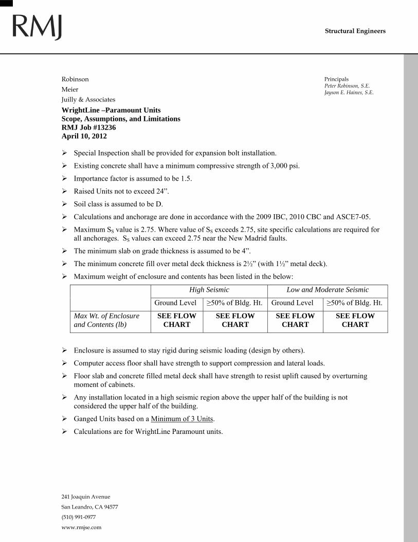
WrightLine –Paramount Units Scope, Assumptions, and Limitations RMJ Job #13236 April 10, 2012
Special Inspection shall be provided for expansion bolt installation.
Existing concrete shall have a minimum compressive strength of 3,000 psi.
Importance factor is assumed to be 1.5.
Raised Units not to exceed 24”.
Soil class is assumed to be D.
Calculations and anchorage are done in accordance with the 2009 IBC, 2010 CBC and ASCE7-05.
Maximum SS value is 2.75. Where value of SS exceeds 2.75, site specific calculations are required for all anchorages. SS values can exceed 2.75 near the New Madrid faults.
The minimum slab on grade thickness is assumed to be 4”.
The minimum concrete fill over metal deck thickness is 2½” (with 1½” metal deck).
Maximum weight of enclosure and contents has been listed in the below:
High Seismic Low and Moderate Seismic
Ground Level ≥50% of Bldg. Ht. Ground Level ≥50% of Bldg. Ht.
Max Wt. of Enclosure and Contents (lb)
SEE FLOW CHART
SEE FLOW CHART
SEE FLOW CHART
SEE FLOW CHART
Enclosure is assumed to stay rigid during seismic loading (design by others).
Computer access floor shall have strength to support compression and lateral loads.
Floor slab and concrete filled metal deck shall have strength to resist uplift caused by overturning moment of cabinets.
Any installation located in a high seismic region above the upper half of the building is not considered the upper half of the building.
Ganged Units based on a Minimum of 3 Units.
Calculations are for WrightLine Paramount units.
Structural Engineers
Robinson
Meier
Juilly & Associates
Principals Peter Robinson, S.E. Jayson E. Haines, S.E.
241 Joaquin Avenue
San Leandro, CA 94577
(510) 991-0977
www.rmjse.com
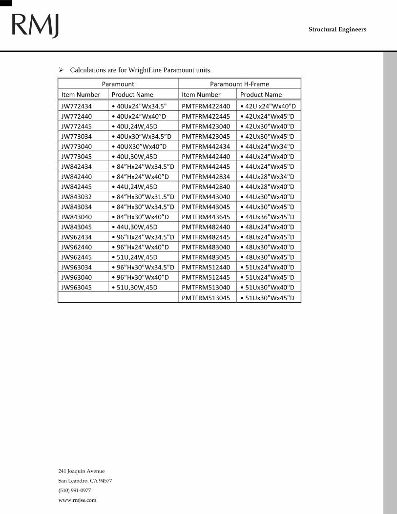
Calculations are for WrightLine Paramount units.
Paramount Paramount H‐Frame
Item Number Product Name Item Number Product Name
JW772434 • 40Ux24"Wx34.5" PMTFRM422440 • 42U x24"Wx40"D
JW772440 • 40Ux24”Wx40”D PMTFRM422445 • 42Ux24"Wx45"D
JW772445 • 40U,24W,45D PMTFRM423040 • 42Ux30"Wx40"D
JW773034 • 40Ux30”Wx34.5”D PMTFRM423045 • 42Ux30"Wx45"D
JW773040 • 40UX30”Wx40”D PMTFRM442434 • 44Ux24"Wx34"D
JW773045 • 40U,30W,45D PMTFRM442440 • 44Ux24"Wx40"D
JW842434 • 84”Hx24”Wx34.5”D PMTFRM442445 • 44Ux24"Wx45"D
JW842440 • 84”Hx24”Wx40”D PMTFRM442834 • 44Ux28"Wx34"D
JW842445 • 44U,24W,45D PMTFRM442840 • 44Ux28"Wx40"D
JW843032 • 84”Hx30”Wx31.5”D PMTFRM443040 • 44Ux30"Wx40"D
JW843034 • 84”Hx30”Wx34.5”D PMTFRM443045 • 44Ux30"Wx45"D
JW843040 • 84”Hx30”Wx40”D PMTFRM443645 • 44Ux36"Wx45"D
JW843045 • 44U,30W,45D PMTFRM482440 • 48Ux24"Wx40"D
JW962434 • 96”Hx24”Wx34.5”D PMTFRM482445 • 48Ux24"Wx45"D
JW962440 • 96”Hx24”Wx40”D PMTFRM483040 • 48Ux30"Wx40"D
JW962445 • 51U,24W,45D PMTFRM483045 • 48Ux30"Wx45"D
JW963034 • 96”Hx30”Wx34.5”D PMTFRM512440 • 51Ux24"Wx40"D
JW963040 • 96”Hx30”Wx40”D PMTFRM512445 • 51Ux24"Wx45"D
JW963045 • 51U,30W,45D PMTFRM513040 • 51Ux30"Wx40"D
PMTFRM513045 • 51Ux30"Wx45"D
Structural Engineers


Wrightline241 Joaquin Avenue Low & Moderate SeismicSan Leandro, CA 94577 Job No. : 13236 Date: 10/01/13(510) 991-0977 By: MAS Page: 8
S P t L & M d t S i i
1.5
Summary: Paramount - Low & Moderate Seismic
Assuptions
Importance Factor:Single
ParamountUnitUnit
Ground Floor >50% of building height
Concrete Slab (4" min)
Site Specific
>0%, <50% of building height
Concrete Fill over metal deck (2½" min.
conc. Cover)
(4" min)
24" raised computer floor
no computer floor
Site Specific
24" raised computer floor
no computer floor
Concrete Fill over metal deck (2½" min.
conc. Cover)
SK3 SK3 SK3 SK3SK3
SK6
SK3
SK8
SK3
SK7
SK3
SK8
Use
Drawing Ref.
Use(4) ½" Di Hil i Use
Use(4) ½" Di Hil i
Max Content Wt.=1,800#
Max Content Wt.=1,800#
Max Content Wt.=1,500#
Max Content Wt.=900#
Use(4) ½" Dia.
Hilti Kwik Bolt KB-TZ,
Embed 2.75" Min.
Use(4) ½" Dia. Hilti
Kwik Bolt KB-TZ, Embed 2.75" Min.
& ½" Dia. Threaded Rod
Use(4) ½" Dia.
Hilti Kwik Bolt KB-TZ, Embed
1¾" Min.
Use(4) ½" Dia. Hilti
Kwik Bolt KB-TZ, Embed 1¾" Min.
& ½" Dia. Threaded Rod
Wrightline241 Joaquin Avenue Low & Moderate SeismicSan Leandro, CA 94577 Job No. : 13236 Date: 10/01/13(510) 991-0977 By: MAS Page: 9
1.5
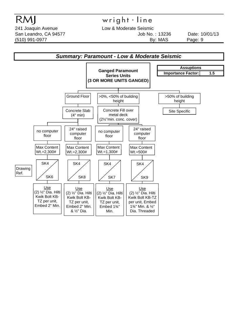
Summary: Paramount - Low & Moderate Seismic
AssuptionsImportance Factor:
Ganged ParamountSeries Units
(3 OR MORE UNITS GANGED)(3 OR MORE UNITS GANGED)
Ground Floor >0%, <50% of building height
Concrete Slab (4" min)
Concrete Fill over metal deck
(2½"min. conc. cover)
>50% of building height
Site Specific(4" min)
no computer floor
no computer floor
metal deck(2½"min. conc. cover)
24" raised computer
floor
24" raised computer
floor
Max Content Wt.=2,300#
Max Content Wt.=2,300#
Max Content Wt.=1,300#
Max Content Wt.=500#
SK4
SK6
SK4
SK8
SK4
SK7
SK4
SK9
Drawing Ref.
Use(2) ½" Dia. Hilti Kwik Bolt KB-
Use(2) ½" Dia. Hilti Kwik Bolt KB-
Use(2) ½" Dia. Hilti Kwik Bolt KB-
Use(2) ½" Dia. Hilti
Kwik Bolt KB-TZ
Wt.=2,300# Wt.=2,300# Wt.=1,300# Wt.=500#
Use(2) ½" Dia. Hilti Kwik Bolt KB-TZ per unit,
Embed 2" Min.
Use(2) ½" Dia. Hilti Kwik Bolt KB-TZ per unit,
Embed 2" Min. & ½" Dia.
Use(2) ½" Dia. Hilti Kwik Bolt KB-TZ per unit, Embed 1¾"
Min.
Use(2) ½" Dia. Hilti
Kwik Bolt KB-TZ per unit, Embed 1¾" Min. & ½" Dia. Threaded

Wrightline241 Joaquin Avenue High SeismicSan Leandro, CA 94577 Job No. : 13236 Date: 10/01/13(510) 991-0977 By: MAS Page: 10
S W i htLi Hi h S i i
1.5
Summary: WrightLine - High Seismic
Assuptions
Importance Factor:Single
ParamountUnit
Ground Floor >0%, <50% of building height
Concrete Slab (4" min)
Concrete Fill over metal deck
no computer 24" raised no computer 24" raised
>50% of building height
Site Specific
no computer floor
24" raised computer floor
no computer floor
24" raised computer floor
SK3
SK6
Drawing Ref.
SK3
SK9
SK3
SK6
SK3
SK9SK6
Ref.
Use(4) ½" Dia. Hilti Kwik Bolt KB-TZ, Embed 2"
SK9
Use(4) ½" Dia. Hilti Kwik Bolt KB-TZ, Embed 2"
SK6
Use(4) ½" Dia. Hilti Kwik Bolt KB-TZ per unit,
SK9
Use(4) ½" Dia. Hilti
Kwik Bolt KB-TZ per unit, Embed
Max Content Wt.=800#
Max Content Wt.=400#
Max Content Wt.=500#
Max Content Wt.=300#
(4) ½ Dia. Hilti Kwik Bolt KB-TZ, Embed 2"
Min.
(4) ½ Dia. Hilti Kwik Bolt KB-TZ, Embed 2"
Min.
(4) ½ Dia. Hilti Kwik Bolt KB-TZ per unit, Embed 1¾"
Min.
(4) ½ Dia. Hilti Kwik Bolt KB-TZ per unit, Embed
1¾" Min. & ½" Dia. Threaded Rod

Wrightline241 Joaquin Avenue High SeismicSan Leandro, CA 94577 Job No. : 13236 Date: 10/01/13(510) 991-0977 By: MAS Page: 11
1.5
Summary: WrightLine - High Seismic
Importance Factor:AssuptionsGanged Paramount
Units(3 OR MORE UNITS
GANGED)GANGED)
Ground Floor
>0%, <50% of building height
Concrete Slab (4" min)
Concrete Fill over metal deck
(2½"min. conc. cover)
>50% of building height
Site Specific
SK5
(4" min) metal deck(2½"min. conc. cover)
no computer floor
24" raised computer floor
no computer floor
24" raised computer floor
SK4SK4
Site Specific
DrawingSK5
SK5
SK9
SK4
SK6
SK4
SK9
Drawing Ref.
Use Use Use
SK5
SK8
Use
Max Content Wt.=1,100#
Max Content Wt.=600#
Max Content Wt.=700#
Max Content Wt.=300#
Use(2) ½" Dia. Hilti
Kwik Bolt KB-TZ per unit, Embed
2" Min.
Use(4) ½" Dia. Hilti
Kwik Bolt KB-TZ per unit, Embed 2" Min. & ½" Dia.
Threaded Rod
Use(2) ½" Dia.
Hilti Kwik Bolt KB-TZ per
unit, Embed 1¾" Min.
Use(4) ½" Dia.
Hilti Kwik Bolt KB-TZ per
unit, Embed 1¾" Min.

Robinson Meier Juilly & Associates
Low & Moderate Seismic Calculations
Structural Engineers
Principals Peter Robinson, S.E. Jayson E. Haines, S.E.
Wrightline241 Joaquin Avenue Low & Moderate SeismicSan Leandro, CA 94577 Job No. : 13236 Date: 10/01/13(510) 991-0977 By: MAS Page: 13
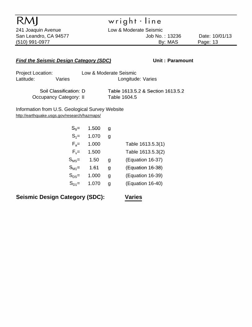
Find the Seismic Design Category (SDC) Unit : Paramount
Project Location: Low & Moderate SeismicLatitude: Varies Varies
D Table 1613 5 2 & Section 1613 5 2
Longitude:
Soil Classification: D Table 1613.5.2 & Section 1613.5.2II Table 1604.5
Information from U.S. Geological Survey Websitehttp://earthquake.usgs.gov/research/hazmaps/
SS= 1.500 g
Soil Classification:Occupancy Category:
SS 1.500 g
S1= 1.070 g
Fa= 1.000 Table 1613.5.3(1)
Fv= 1.500 Table 1613.5.3(2)
SMS= 1.50 g (Equation 16-37)
SM1= 1 61 g (Equation 16-38)SM1= 1.61 g (Equation 16-38)
SDS= 1.000 g (Equation 16-39)
SD1= 1.070 g (Equation 16-40)
Seismic Design Category (SDC): Varies

Wrightline241 Joaquin Avenue Low & Moderate SeismicSan Leandro, CA 94577 Job No. : 13236 Date: 10/01/13(510) 991-0977 By: MAS Page: 14
Load Case: Single Unit (Ground Flr )Load Case:
Width(w) (in) = 24 Edge Length 3 in
Depth(D) (in) = 34.5Frame Height (in) = 96 SDS = 1.0
Unit Weight (lb) = 230 Ip = 1.5 (Importance)
Single Unit (Ground Flr.)
Unit Dimensions
Seismic Force
Center of Gravity Location
Low & Moderate Seismic
g ( )
Unit Part Weight (lbs) X (in) Y (in) Z (in) ap = 1.0 (Cabinets)
Paramount Frame +Contents 2,030 12 12 48 Rp = 2.5 (Cabinets)
Content Weight (lb) 1800 z/h = 0.0 (Ground Floor)
Longitudinal Anchorage Spacing (in) = 24 Fp = 0.240 W
Transverse Anchorage Spacing (in) = 18 Fp,min = 0.45 WFp,max = 2.40 W
y
Use Fp = 0.45 W
Longitudinal OverturningOverturning
Moment = 0.45 (48 in. x 2030lbs.) = 43,848 lb-in
0.9xResisting
Paramount unit Plan
Longitudinal Seismic Force (Fp)0.9xResisting
Moment = 0.9 [2030 lbs. x (9in)]= 16,443 lb-in 24 in.
Total # of Bolts = 4 Anchorage Force = 761 lbs/per boltShear Force = 457 lbs/per bolt
18 in.
Longitudinal Seismic Force (Fp)
Transverse OverturningOverturning
Moment = 0.45 (48 in. x 2030lbs.) = 43,848 lb-in
24 in
Design Bolts for 761 lbs tension, 457 lbs. shear, longitudinal direction
Paramount unit Plan
Transverse 24 in.0.9xResisting
Moment = 0.9 [2030 lbs. x (12in.)]= 21,924 lb-in
Total # of Bolts = 4 Anchorage Force = 457 lbs/per boltShear Force = 457 lbs/per bolt
18 in.Design Bolts for 0 lbs tension, 457 lbs. shear, transverse direction
TransverseSeismic Force (Fp)
g , ,
Drawing Reference See: SK-3 & SK-6

Wrightline241 Joaquin Avenue Low & Moderate SeismicSan Leandro, CA 94577 Job No. : 13236 Date: 10/01/13(510) 991-0977 By: MAS Page: 15
Load Case Single Unit on 24" Raised Computer Floor (Ground Flr )Load Case:
Width(w) (in) = 24 Edge Length 3 inDepth(D) (in) = 34.5 Raised Floor Height = 24 in SDS = 1.0
Frame Height (in) = 96 Ip = 1.5 (Importance)
Unit Weight (lb) = 230 ap = 1.0 (Cabinets)
Single Unit on 24" Raised Computer Floor (Ground Flr.)
Low & Moderate Seismic
Unit Dimensions Seismic Force
Center of Gravity LocationUnit Weight (lb) = 230 ap 1.0 (Cabinets)
Unit Part Weight (lbs) X (in) Y (in) Z (in) Rp = 2.5 (Cabinets)
Paramount Frame +Contents 2,030 12 12 72 z/h = 0.0 (Ground Floor)
Content Weight (lb) 1800 Fp = 0.240 W
Longitudinal Anchorage Spacing (in) = 24 Fp,min = 0.45 W
Transverse Anchorage Spacing (in) = 18 Fp,max = 2.40 W
Use F = 0 45 W
Center of Gravity Location
Use Fp = 0.45 W
Longitudinal OverturningOverturning
Moment = 0.45 (72 in. x 2030lbs.) = 65,772 lb-in
0.9xResistingMoment = 0 9 [2030 lbs x (12in )]= 21 924 lb in 24 in
Paramount unit Plan
Longitudinal Seismic Force (Fp)
Moment = 0.9 [2030 lbs. x (12in.)]= 21,924 lb-in 24 in.
Total # of Bolts = 4 Anchorage Force = 914 lbs/per boltShear Force = 457 lbs/per bolt
18 in.Design Bolts for 914 lbs tension, 457 lbs. shear, longitudinal direction
Force (Fp)
Transverse OverturningOverturning
Moment = 0.45 (72 in. x 2030lbs.) = 65,772 lb-in
24 in.0 9xResisting
Design Bolts for 914 lbs tension, 457 lbs. shear, longitudinal direction
Paramount unit Plan
TransverseSeismic Force (Fp)
0.9xResistingMoment = 0.9 [2030 lbs. x (12in)]= 21,924 lb-in
Total # of Bolts = 4 Anchorage Force = 914 lbs/per boltShear Force = 457 lbs/per bolt
18 in.Design Bolts for 914 lbs tension, 457 lbs. shear, transverse direction
TransverseSeismic Force (Fp)
SK-3 & SK-8Drawing Reference See:

Wrightline241 Joaquin Avenue Low & Moderate SeismicSan Leandro, CA 94577 Job No. : 13236 Date: 10/01/13(510) 991-0977 By: MAS Page: 16
Load Case Ganged Unit (Ground Flr )Load Case:
# of Units ganged (min.)= 3
Width(w) (in) = 24 Edge Length 3 inDepth(D) (in) = 34.5 SDS = 1.0
Ganged Unit (Ground Flr.)
Low & Moderate Seismic
Single Unit Dimension Seismic Force
Depth(D) (in) = 34.5 SDS = 1.0
Frame Height (in) = 96 Ip = 1.5 (Importance)
Frame Weight (lb.) = 230 ap = 1.0 (Cabinets)
Unit Part Weight (lbs) X (in) Y (in) Z (in) Rp = 2.5 (Cabinets)
3 - Paramount Frame +Contents 7,590 21 12 48 z/h = 0.0 (Ground Floor)
Content Weight (lb) 2300 Fp = 0.240 W
Longitudinal Anchorage Spacing (in) = 24 F i = 0 45 W
Center of Gravity Location
Seismic
Longitudinal Anchorage Spacing (in) = 24 Fp,min = 0.45 W
Transverse Anchorage Spacing (in) = 42 Fp,max = 2.40 W
Use Fp = 0.45 W
Longitudinal OverturningOverturning
Moment = 0.45 (96/2 in. x 7590lbs.) = 163,944 lb-in Paramount unit PlanLongitudinal Seismic Force
0.9xResistingMoment = 0.9 (7590 lbs. x21 in.)= 143,451 lb-in
Anchorage Force = 488 lbs 3 ganged unitsShear Force = 1,139 lbs/per bolt # of bolts per unit = 2
D i B lt f 0 lb t i 1 139 lb h l it di l di ti
Longitudinal Seismic Force
Transverse OverturningOverturning
Moment = 0.45 (96/2 in. x 7590lbs.) = 163,944 lb-in
0.9xResisting
Design Bolts for 0 lbs tension, 1,139 lbs. shear, longitudinal direction
Ganged Paramount unit PlanTransverse Seismic Force
gMoment = 0.9 (7590 lbs x12 in.) = 81,972 lb-in
Anchorage Force = 1,139 lbs/per bolt 3 ganged unitsShear Force = 1,139 lbs/per bolt # of bolts per unit = 2
Design Bolts for 1 lbs tension, 1,139 lbs. shear, transverse direction
SK-4 & SK-6Drawing Reference See:

Wrightline241 Joaquin Avenue Low & Moderate SeismicSan Leandro, CA 94577 Job No. : 13236 Date: 10/01/13(510) 991-0977 By: MAS Page: 17
L d C G d U it 24" R i d C Fl (G d Fl )Load Case:
# of Units ganged (min.)= 3 Raised Floor = 24 in
Width(w) (in) = 24 Edge Length 3 inDepth(D) (in) = 34.5 SDS = 1.0
Ganged Unit on 24" Raised Comp. Flr. (Ground Flr.)
Seismic Force
Low & Moderate Seismic
Single Unit Dimension
p ( ) ( )
Frame Height (in) = 96 Ip = 1.5 (Importance)
Frame Weight (lb.) = 230 ap = 1.0 (Cabinets)
Unit Part Weight (lbs) X (in) Y (in) Z (in) Rp = 2.5 (Cabinets)
3 - Paramount Frame +Contents 7,590 66 12 72 z/h = 0.0 (Ground Floor)
Content Weight (lb) 2300 Fp = 0.240 W
Longitudinal Anchorage Spacing (in) = 34.5 Fp,min = 0.45 W
Center of Gravity Location
Longitudinal Anchorage Spacing (in) 34.5 p,min 0.45 W
Transverse Anchorage Spacing (in) = 54 Fp,max = 2.40 W
Use Fp = 0.45 W
Longitudinal OverturningOverturning
Moment = 0.5 (72 in. x 7590lbs.) = 245,916 lb-in
0 9 R i ti
Ganged Paramount unit PlanLongitudinal Seismic Force
0.9xResistingMoment = 0.9 (7590 lbs. x66 in.)= 450,846 lb-in
Anchorage Force = 0 lbs/per bolt 3 ganged unitsShear Force = 1,139 lbs/per bolt # of bolts per unit = 2
Design Bolts for 0 lbs tension 1 139 lbs shear longitudinal direction
Longitudinal Seismic Force
Transverse OverturningOverturning
Moment = 0.5 (72in. x 7590lbs.) = 245,916 lb-in
0.9xResistingMoment = 0 9 (7590 lb 17 25 i ) 117 835 lb in
Ganged Paramount unit Plan
Design Bolts for 0 lbs tension, 1,139 lbs. shear, longitudinal direction
Transverse Seismic Force
Moment = 0.9 (7590 lbs x17.25 in.) = 117,835 lb-in
Anchorage Force = 1,238 lbs/per bolt 3 ganged unitsShear Force = 1,139 lbs/per bolt # of bolts per unit = 2
SK 4 & SK 9Drawing Reference See:
Design Bolts for 1,238 lbs tension, 1,139 lbs. shear, transverse direction
SK-4 & SK-9Drawing Reference See:
Wrightline241 Joaquin Avenue Low & Moderate SeismicSan Leandro, CA 94577 Job No. : 13236 Date: 10/01/13(510) 991-0977 By: MAS Page: 18
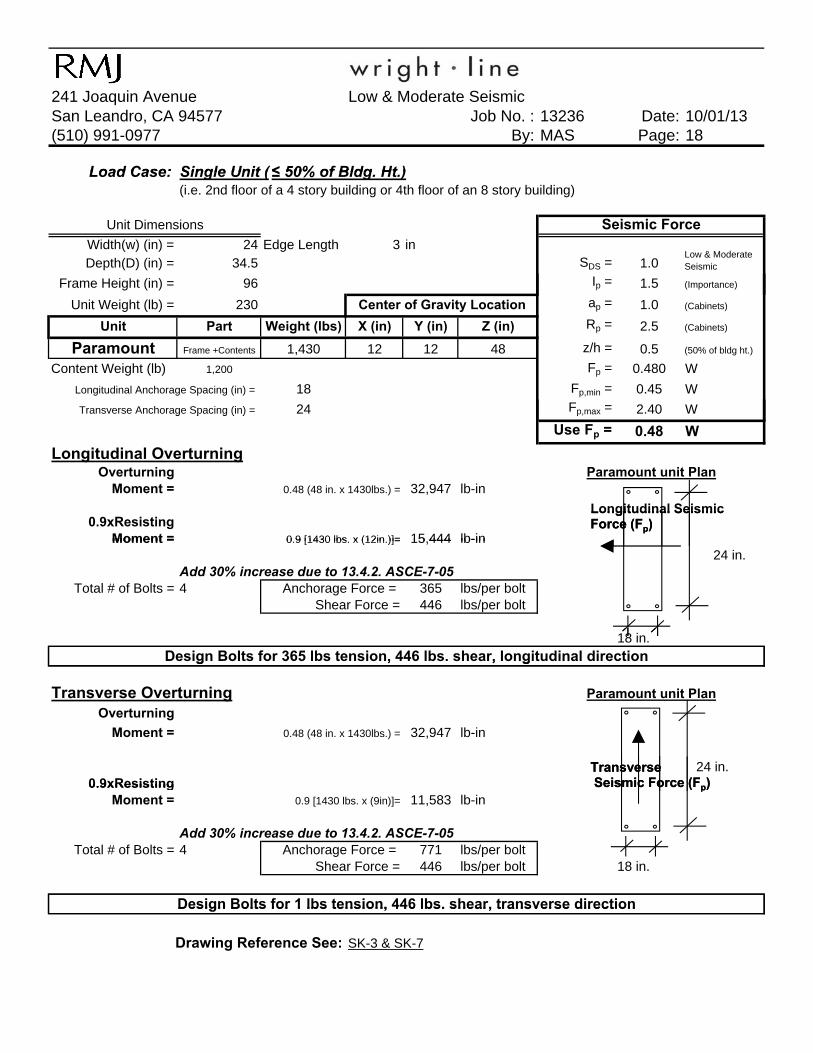
Load Case: Single Unit ( ≤ 50% of Bldg Ht )Load Case:(i.e. 2nd floor of a 4 story building or 4th floor of an 8 story building)
Width(w) (in) = 24 Edge Length 3 inDepth(D) (in) = 34.5 SDS = 1.0
Frame Height (in) = 96 Ip = 1.5 (Importance)
Single Unit ( ≤ 50% of Bldg. Ht.)
Low & Moderate Seismic
Unit Dimensions Seismic Force
Unit Weight (lb) = 230 ap = 1.0 (Cabinets)
Unit Part Weight (lbs) X (in) Y (in) Z (in) Rp = 2.5 (Cabinets)
Paramount Frame +Contents 1,430 12 12 48 z/h = 0.5 (50% of bldg ht.)
Content Weight (lb) 1,200 Fp = 0.480 W
Longitudinal Anchorage Spacing (in) = 18 Fp,min = 0.45 W
Transverse Anchorage Spacing (in) = 24 Fp,max = 2.40 W
Center of Gravity Location
g p g ( ) p,
Use Fp = 0.48 W
Longitudinal OverturningOverturning
Moment = 0.48 (48 in. x 1430lbs.) = 32,947 lb-in
0.9xResistingMoment = 0 9 [1430 lbs x (12in )]= 15 444 lb-in
Paramount unit Plan
Longitudinal Seismic Force (Fp)
Moment = 0.9 [1430 lbs. x (12in.)]= 15,444 lb-in 24 in.
Add 30% increase due to 13.4.2. ASCE-7-05Total # of Bolts = 4 Anchorage Force = 365 lbs/per bolt
Shear Force = 446 lbs/per bolt
18 in.Design Bolts for 365 lbs tension, 446 lbs. shear, longitudinal direction
Longitudinal Seismic Force (Fp)
Transverse OverturningOverturning
Moment = 0.48 (48 in. x 1430lbs.) = 32,947 lb-in
24 in.0.9xResisting
g , , g
Paramount unit Plan
TransverseSeismic Force (Fp)0.9xResisting
Moment = 0.9 [1430 lbs. x (9in)]= 11,583 lb-in
Add 30% increase due to 13.4.2. ASCE-7-05Total # of Bolts = 4 Anchorage Force = 771 lbs/per bolt
Shear Force = 446 lbs/per bolt 18 in.
Design Bolts for 1 lbs tension, 446 lbs. shear, transverse direction
TransverseSeismic Force (Fp)
Design Bolts for 1 lbs tension, 446 lbs. shear, transverse direction
SK-3 & SK-7Drawing Reference See:

Wrightline241 Joaquin Avenue Low & Moderate SeismicSan Leandro, CA 94577 Job No. : 13236 Date: 10/01/13(510) 991-0977 By: MAS Page: 19
Load Case: Single Unit on 24" Raised Comp Flr (≤ 50% of Bldg Ht )Load Case:(i.e. 2nd floor of a 4 story building or 4th floor of an 8 story building)
Raised Floor = 24 in
Width(w) (in) = 24 Edge Length 3 inDepth(D) (in) = 34.5 SDS = 1.0
Frame Height (in) = 96 Ip = 1.5 (Importance)
Single Unit on 24" Raised Comp. Flr. (≤ 50% of Bldg. Ht.)
Seismic ForceUnit Dimensions
Low & Moderate Seismic
Unit Weight (lb) = 230 ap = 1.0 (Cabinets)
Unit Part Weight (lbs) X (in) Y (in) Z (in) Rp = 2.5 (Cabinets)
Paramount Frame +Contents 1,130 12 12 72 z/h = 0.5 (50% of bldg ht.)
Content Weight (lb) 900 Fp = 0.480 W
Longitudinal Anchorage Spacing (in) = 24 Fp,min = 0.45 W
Transverse Anchorage Spacing (in) = 18 Fp,max = 2.40 W
Center of Gravity Location
Use Fp = 0.48 W
Longitudinal OverturningOverturning
Moment = 0.48 (72 in. x 1130lbs.) = 39,053 lb-in
0.9xResistingMoment = 0.9 [1130 lbs. x (12in)]= 12,204 lb-in
Paramount unit Plan
Longitudinal Seismic Force (Fp)Moment 0.9 [1130 lbs. x (12in)] 12,204 lb in
24 in.Add 30% increase due to 13.4.2. ASCE-7-05
Total # of Bolts = 4 Anchorage Force = 970 lbs/per boltShear Force = 353 lbs/per bolt
18 in.D i B lt f 970 lb t i 353 lb h l it di l di ti
Longitudinal Seismic Force (Fp)
Transverse OverturningOverturning
Moment = 0.48 (72 in. x 1130lbs.) = 39,053 lb-in
0.9xResisting 24 in.
Design Bolts for 970 lbs tension, 353 lbs. shear, longitudinal direction
Paramount unit Plan
TransverseSeismic Force (Fp)
gMoment = 0.9 [1130 lbs. x (12in.)]= 12,204 lb-in
Add 30% increase due to 13.4.2. ASCE-7-05Total # of Bolts = 4 Anchorage Force = 727 lbs/per bolt
Shear Force = 353 lbs/per bolt18 in.
Design Bolts for 727 lbs tension 353 lbs shear transverse direction
TransverseSeismic Force (Fp)
SK-3 & SK-9Drawing Reference See:
Design Bolts for 727 lbs tension, 353 lbs. shear, transverse direction

Wrightline241 Joaquin Avenue Low & Moderate SeismicSan Leandro, CA 94577 Job No. : 13236 Date: 10/01/13(510) 991-0977 By: MAS Page: 20
Load Case: Ganged Unit (≤ 50% of Bldg Ht )Load Case:
# of Units ganged (max)= 3
Width(w) (in) = 24 Edge Length 3 inDepth(D) (in) = 34.5 SDS = 1.0
Low & Moderate Seismic
Ganged Unit (≤ 50% of Bldg. Ht.)
Seismic ForceSingle Unit Dimension
Depth(D) (in) 34.5 SDS 1.0
Frame Height (in) = 96 Ip = 1.5 (Importance)
Frame Weight (lb.) = 230 ap = 1.0 (Cabinets)
Unit Part Weight (lbs) X (in) Y (in) Z (in) Rp = 2.5 (Cabinets)
3 - Paramount Frame +Contents 4,590 21 12 48 z/h = 0.5 (50% of bldg ht.)
Content Weight (lb) 1,300 Fp = 0.480 W
Longitudinal Anchorage Spacing (in) = 24 F i = 0 45 W
Center of Gravity Location
Seismic
Longitudinal Anchorage Spacing (in) = 24 Fp,min = 0.45 W
Transverse Anchorage Spacing (in) = 42 Fp,max = 2.40 W
Use Fp = 0.48 W
Longitudinal OverturningOverturning
Moment = 0.48 (96/2 in. x 4590lbs.) = 105,754 lb-in Ganged Paramount unit PlanLongitudinal Seismic Force
0.9xResistingMoment = 0.9 (4590 lbs. x21 in.)= 86,751 lb-in
Add 30% increase due to 13.4.2. ASCE-7-05Anchorage Force = 294 lbs 3 ganged units
Shear Force = 955 lbs/per bolt # of bolts per unit = 2
Design Bolts for 294 lbs tension 955 lbs shear longit dinal direction
Longitudinal Seismic Force
Transverse OverturningOverturning
Moment = 0.48 (96/2 in. x 4590lbs.) = 105,754 lb-in
0.9xResisting
Ganged Paramount unit Plan
Design Bolts for 294 lbs tension, 955 lbs. shear, longitudinal direction
Transverse Seismic Force
gMoment = 0.9 (4590 lbs x12 in.) = 49,572 lb-in
Add 30% increase due to 13.4.2. ASCE-7-05Anchorage Force = 1,014 lbs/per bolt 3 ganged units
Shear Force = 955 lbs/per bolt # of bolts per unit = 2
Design Bolts for 1 lbs tension, 955 lbs. shear, transverse direction
Drawing Reference See: SK-4 & SK-7
Wrightline241 Joaquin Avenue Low & Moderate SeismicSan Leandro, CA 94577 Job No. : 13236 Date: 10/01/13(510) 991-0977 By: MAS Page: 21
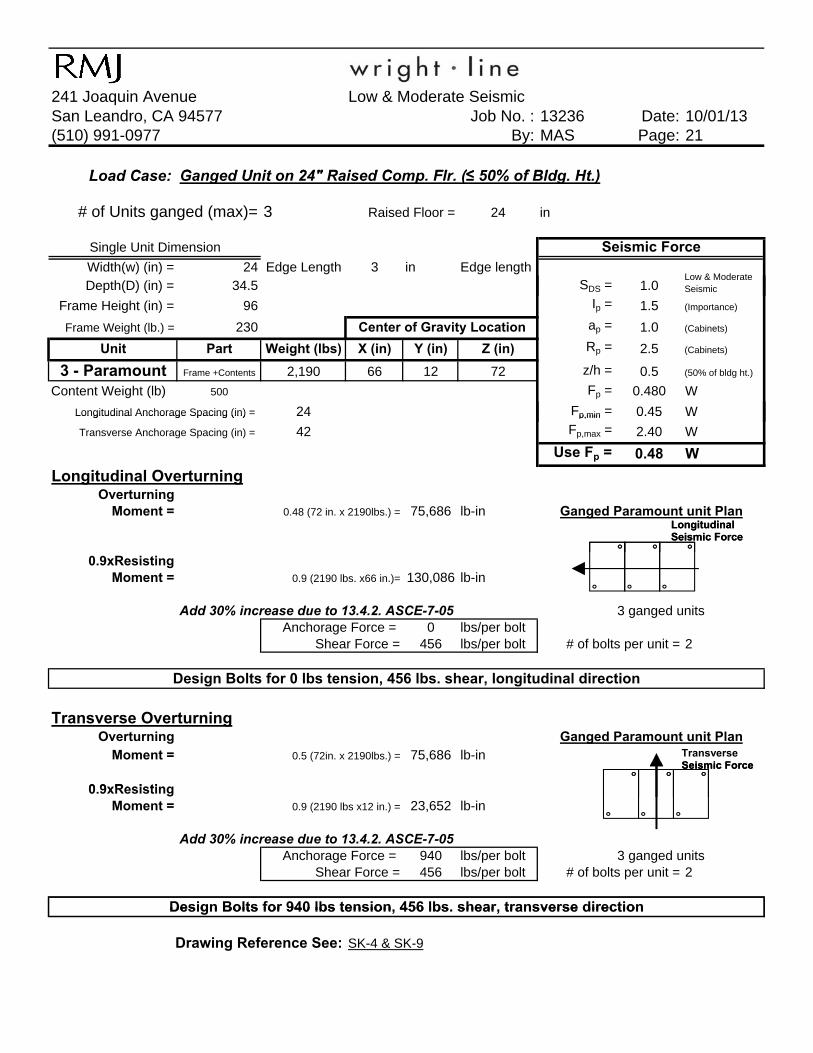
L d C G d U it 24" R i d C Fl (≤ 50% f Bld Ht )Load Case:
# of Units ganged (max)= 3 Raised Floor = 24 in
Width(w) (in) = 24 Edge Length 3 in Edge lengthDepth(D) (in) = 34.5 SDS = 1.0
Single Unit Dimension
Ganged Unit on 24" Raised Comp. Flr. (≤ 50% of Bldg. Ht.)
Seismic Force
Low & Moderate Seismicp ( ) ( )
Frame Height (in) = 96 Ip = 1.5 (Importance)
Frame Weight (lb.) = 230 ap = 1.0 (Cabinets)
Unit Part Weight (lbs) X (in) Y (in) Z (in) Rp = 2.5 (Cabinets)
3 - Paramount Frame +Contents 2,190 66 12 72 z/h = 0.5 (50% of bldg ht.)
Content Weight (lb) 500 Fp = 0.480 W
Longitudinal Anchorage Spacing (in) = 24 Fp,min = 0.45 W
Center of Gravity Location
Longitudinal Anchorage Spacing (in) 24 p,min 0.45 W
Transverse Anchorage Spacing (in) = 42 Fp,max = 2.40 W
Use Fp = 0.48 W
Longitudinal OverturningOverturning
Moment = 0.48 (72 in. x 2190lbs.) = 75,686 lb-in Ganged Paramount unit PlanLongitudinal Seismic Force
0.9xResistingMoment = 0.9 (2190 lbs. x66 in.)= 130,086 lb-in
Add 30% increase due to 13.4.2. ASCE-7-05 3 ganged unitsAnchorage Force = 0 lbs/per bolt
Shear Force = 456 lbs/per bolt # of bolts per unit = 2
Longitudinal Seismic Force
Transverse OverturningOverturning
Moment = 0.5 (72in. x 2190lbs.) = 75,686 lb-in
0 9xResisting
Ganged Paramount unit Plan
Design Bolts for 0 lbs tension, 456 lbs. shear, longitudinal direction
Transverse Seismic Force
0.9xResistingMoment = 0.9 (2190 lbs x12 in.) = 23,652 lb-in
Add 30% increase due to 13.4.2. ASCE-7-05Anchorage Force = 940 lbs/per bolt 3 ganged units
Shear Force = 456 lbs/per bolt # of bolts per unit = 2
Design Bolts for 940 lbs tension, 456 lbs. shear, transverse direction
Seismic Force
SK-4 & SK-9Drawing Reference See:
Design Bolts for 940 lbs tension, 456 lbs. shear, transverse direction

Robinson Meier Juilly & Associates
High Seismic Calculations
Structural Engineers
Principals Peter Robinson, S.E. Jayson E. Haines, S.E.

Wrightline241 Joaquin Avenue High SeismicSan Leandro, CA 94577 Job No. : 13236 Date: 10/01/13(510) 991-0977 By: MAS Page: 23
Find the Seismic Design Category (SDC) Unit : Paramount
Project Location: High SeismicLatitude: Varies Varies
D Table 1613 5 2 & Section 1613 5 2
Longitude:
Soil Classification: D Table 1613.5.2 & Section 1613.5.2II Table 1604.5
Information from U.S. Geological Survey Websitehttp://earthquake.usgs.gov/research/hazmaps/
SS= 2.750 g
Occupancy Category:Soil Classification:
SS 2.750 g
S1= 1.070 g
Fa= 1.000 Table 1613.5.3(1)
Fv= 1.500 Table 1613.5.3(2)
SMS= 2.75 g (Equation 16-37)
SM1= 1 61 g (Equation 16-38)SM1= 1.61 g (Equation 16-38)
SDS= 1.833 g (Equation 16-39)
SD1= 1.070 g (Equation 16-40)
Seismic Design Category (SDC): Varies

Wrightline241 Joaquin Avenue High SeismicSan Leandro, CA 94577 Job No. : 13236 Date: 10/01/13(510) 991-0977 By: MAS Page: 24
Load Case: Single Unit (Ground Flr.)
Width(w) (in) = 24 Edge Length 3 in SDS = 1.83 High Seismic
Depth(D) (in) = 34.5 Ip = 1.5 (Importance)
Frame Height (in) = 96 ap = 1.0 (Cabinets)
Unit Weight (lb.) = 230 Rp = 2.5 (Cabinets)
Unit Part Weight (lbs) X (in) Y (in) Z (in) z/h = 0.0 (Ground Floor)
Paramount Frame +Contents 1,030 12 12 48 Fp = 0.440 W
Content Weight (lb) 800 Fp,min = 0.83 W
Longitudinal Anchorage Spacing (in) = 24 Fp,max = 4.40 W
Transverse Anchorage Spacing (in) = 18 Use Fp = 0.83 W
Longitudinal OverturningOverturning
Moment = 0.83 (48 in. x 1030lbs.) = 40,788 lb-in
0.9xResistingMoment = 0.9 [(1030 lbs. - Vert. Comp.) x 12in.]= 7,045 lb-in
378 lbs 24 in.
Center of Gravity Location
Unit Dimensions Seismic Force
Paramount unit Plan
Vertical Component (0.2*SDS*Wp) =
Longitudinal Seismic Force (Fp)
Add 30% increase due to 13.4.2. ASCE-7-05Total # of Bolts = 4 Anchorage Force = 1,218 lbs/per bolt
Shear Force = 552 lbs/per bolt
18 in.
Transverse OverturningOverturning
Moment = 0.83 (48 in. x 1030lbs.) = 40,788 lb-in
0.9xResisting 24 in.Moment = 0.9 [(1030 lbs. - Vert. Comp.) x (12in.)]= 7,045 lb-in
378 lbsAdd 30% increase due to 13.4.2. ASCE-7-05
Total # of Bolts = 4 Anchorage Force = 914 lbs/per boltShear Force = 552 lbs/per bolt
18 in.
SK-3 & SK-6
Paramount unit Plan
Design Bolts for 914 lbs tension, 552 lbs. shear, longitudinal direction
Drawing Reference See:
Design Bolts for 1,218 lbs tension, 552 lbs. shear, longitudinal direction
Vertical Component (0.2*SDS*Wp) =
TransverseSeismic Force (Fp)

Wrightline241 Joaquin Avenue High SeismicSan Leandro, CA 94577 Job No. : 13236 Date: 10/01/13(510) 991-0977 By: MAS Page: 25
Load Case: Single Unit on 24" Raised Computer Floor (Ground Flr.)
24 in
Width(w) (in) = 24 Edge Length 3 in SDS = 1.83 High Seismic
Depth(D) (in) = 34.5 Ip = 1.5 (Importance)
Frame Height (in) = 96 ap = 1.0 (Cabinets)
Unit Weight (lb.) = 230 Rp = 2.5 (Cabinets)
Unit Part Weight (lbs) X (in) Y (in) Z (in) z/h = 0.0 (Ground Floor)
Paramount Frame +Contents 630 12 12 72 Fp = 0.440 W
Content Weight (lb) 400 Fp,min = 0.83 W
Longitudinal Anchorage Spacing (in) = 24 Fp,max = 4.40 W
Transverse Anchorage Spacing (in) = 18 Use Fp = 0.83 W
Longitudinal OverturningOverturning
Moment = 0.83 (72 in. x 630lbs.) = 37,422 lb-in
0.9xResistingMoment = 0 9 [(630 lbs - Vert Comp ) x (12in )]= 4,309 lb-in 24 in.
Paramount unit Plan
Seismic Force
Center of Gravity Location
Raised Floor =Unit Dimensions
Longitudinal Seismic Force (Fp)
Moment 0.9 [(630 lbs. Vert. Comp.) x (12in.)] 4,309 lb in 24 in.231 lbs
Add 30% increase due to 13.4.2. ASCE-7-05Total # of Bolts = 4 Anchorage Force = 1,196 lbs/per bolt
Shear Force = 338 lbs./per bolt18 in.
Transverse OverturningOverturning
Moment = 0.83 (72 in. x 630lbs.) = 37,422 lb-in
0.9xResisting 24 in.Moment = 0.9 [(630 lbs. - Vert. Comp.) x (12in)]= 4,309 lb-in
231 lbs
Add 30% increase due to 13.4.2. ASCE-7-05Total # of Bolts = 4 Anchorage Force = 897 lbs/per bolt
Shear Force = 552 lbs/per bolt 18 in.
Vertical Component (0.2*SDS*Wp) =
Paramount unit Plan
Design Bolts for 1,196 lbs tension, 338 lbs. shear, longitudinal direction
Vertical Component (0.2*SDS*Wp) =
Design Bolts for 897 lbs tension, 552 lbs. shear, longitudinal direction
Drawing Reference See: SK-3 & SK-9
TransverseSeismic Force (Fp)

Wrightline241 Joaquin Avenue High SeismicSan Leandro, CA 94577 Job No. : 13236 Date: 10/01/13(510) 991-0977 By: MAS Page: 26
Load Case: Ganged Unit (Ground Flr.)
# of Units ganged (min)= 3
Width(w) (in) = 24 Edge Length 3 in SDS = 1.83 High Seismic
Depth(D) (in) = 34.5 Ip = 1.5 (Importance)
Frame Height (in) = 96 ap = 1.0 (Cabinets)
Unit Weight (lb.) = 230 Rp = 2.5 (Cabinets)
Unit Part Weight (lbs) X (in) Y (in) Z (in) z/h = 0.0 (Ground Floor)
3 - Paramount Frame +Contents 3,990 21 12 48 Fp = 0.440 W
Content Weight (lb) 1,100 Fp,min = 0.83 WFp,max = 4.40 W
Longitudinal Anchorage Spacing (in) = 24 Use Fp = 0.83 WTransverse Anchorage Spacing (in) = 42
Longitudinal OverturningOverturning
Moment = 0.83 (96/2 in. x 3990lbs.) = 158,004 lb-in
Single Unit Dimension Seismic Force
Center of Gravity Location
Ganged Paramount unit PlanLongitudinal
0.9xResistingMoment = 0.9 [(3990 lbs. - Vert. Comp.) x21 in.]= 47,760 lb-in
1,463 lbsAdd 30% increase due to 13.4.2. ASCE-7-05
Anchorage Force = 853 lbs/per bolt 3 ganged unitsShear Force = 713 lbs/per bolt Total # of bolts = 4
Transverse OverturningOverturning
Moment = 0.83 (96/2 in. x 3990lbs.) = 158,004 lb-in
0.9xResistingMoment = 0.9 [(3990 lbs - Vert. Comp.) x12 in.] = 27,292 lb-in
1,463 lbsAdd 30% increase due to 13.4.2. ASCE-7-05 3 ganged units
Anchorage Force = 1,180 lbs/per bolt Total # of bolts = 4Shear Force = 713 lbs/per bolt
Vertical Component (0.2*SDS*Wp) =
Vertical Component (0.2*SDS*Wp) =
Design Bolts for 853 lbs tension, 713 lbs. shear, longitudinal direction
Drawing Reference See:
Design Bolts for 1,180 lbs tension, 713 lbs. shear, transverse direction
Ganged Paramount unit Plan
SK-4 & SK-6
Longitudinal Seismic Force
Transverse Seismic Force
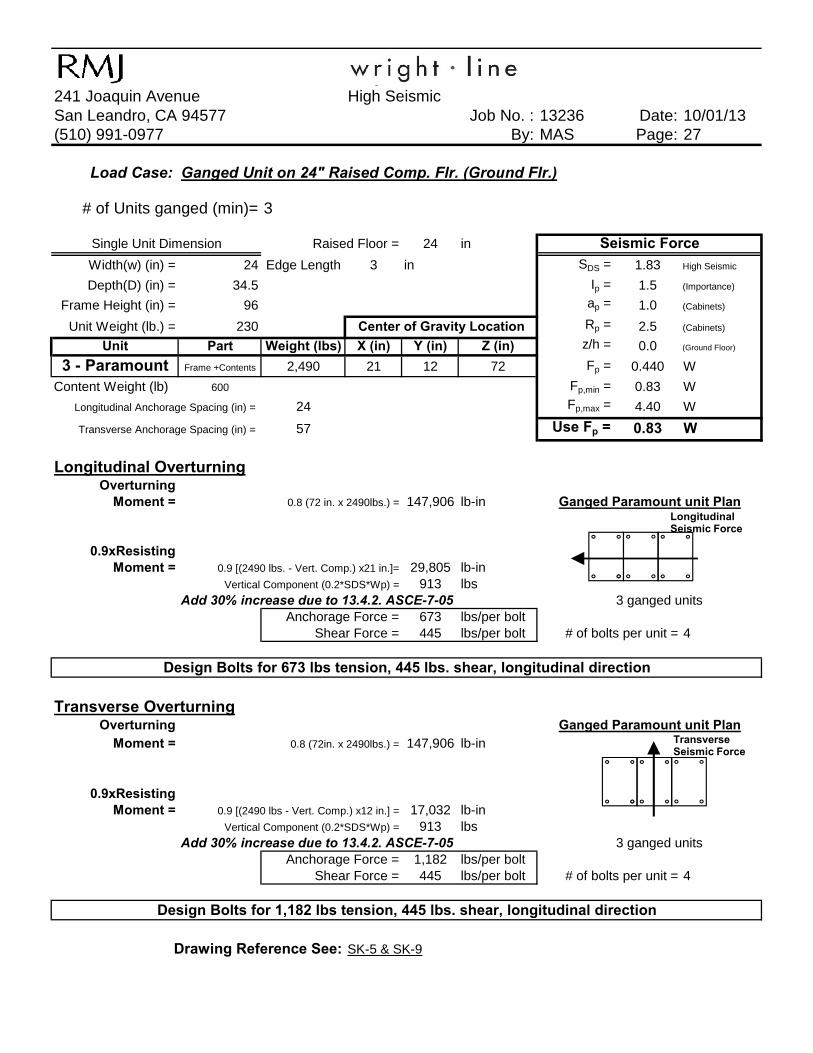
Wrightline241 Joaquin Avenue High SeismicSan Leandro, CA 94577 Job No. : 13236 Date: 10/01/13(510) 991-0977 By: MAS Page: 27
Load Case: Ganged Unit on 24" Raised Comp. Flr. (Ground Flr.)
# of Units ganged (min)= 3
24 in
Width(w) (in) = 24 Edge Length 3 in SDS = 1.83 High Seismic
Depth(D) (in) = 34.5 Ip = 1.5 (Importance)
Frame Height (in) = 96 ap = 1.0 (Cabinets)
Unit Weight (lb.) = 230 Rp = 2.5 (Cabinets)
Unit Part Weight (lbs) X (in) Y (in) Z (in) z/h = 0.0 (Ground Floor)
3 - Paramount Frame +Contents 2,490 21 12 72 Fp = 0.440 W
Content Weight (lb) 600 Fp,min = 0.83 W
Longitudinal Anchorage Spacing (in) = 24 Fp,max = 4.40 W
Transverse Anchorage Spacing (in) = 57 Use Fp = 0.83 W
Longitudinal OverturningOverturning
Moment = 0.8 (72 in. x 2490lbs.) = 147,906 lb-in
Single Unit Dimension
Ganged Paramount unit Plan
Center of Gravity Location
Seismic ForceRaised Floor =
Longitudinal Seismic Force
0.9xResistingMoment = 0.9 [(2490 lbs. - Vert. Comp.) x21 in.]= 29,805 lb-in
913 lbsAdd 30% increase due to 13.4.2. ASCE-7-05 3 ganged units
Anchorage Force = 673 lbs/per boltShear Force = 445 lbs/per bolt # of bolts per unit = 4
Transverse OverturningOverturning
Moment = 0.8 (72in. x 2490lbs.) = 147,906 lb-in
0.9xResistingMoment = 0.9 [(2490 lbs - Vert. Comp.) x12 in.] = 17,032 lb-in
913 lbsAdd 30% increase due to 13.4.2. ASCE-7-05 3 ganged units
Anchorage Force = 1,182 lbs/per boltShear Force = 445 lbs/per bolt # of bolts per unit = 4
SK-5 & SK-9
Ganged Paramount unit Plan
Drawing Reference See:
Vertical Component (0.2*SDS*Wp) =
Vertical Component (0.2*SDS*Wp) =
Design Bolts for 673 lbs tension, 445 lbs. shear, longitudinal direction
Design Bolts for 1,182 lbs tension, 445 lbs. shear, longitudinal direction
Transverse Seismic Force

Wrightline241 Joaquin Avenue High SeismicSan Leandro, CA 94577 Job No. : 13236 Date: 10/01/13(510) 991-0977 By: MAS Page: 28
Load Case: Single Unit ( ≤ 50% of Bldg. Ht.)(i.e. 2nd floor of a 4 story building or 4th floor of an 8 story building)
Width(w) (in) = 24 Edge Length 3 in SDS = 1.83 High Seismic
Depth(D) (in) = 34.5 Ip = 1.5 (Importance)
Frame Height (in) = 96 ap = 1.0 (Cabinets)
Unit Weight (lb.) = 230 Rp = 2.5 (Cabinets)
Unit Part Weight (lbs) X (in) Y (in) Z (in) z/h = 0.5 (50% of bldg ht.)
Paramount Frame +Contents 730 12 12 48 Fp = 0.880 W
Content Weight (lb) 500 Fp,min = 0.83 W
Longitudinal Anchorage Spacing (in) = 24 Fp,max = 4.40 W
Transverse Anchorage Spacing (in) = 18 Use Fp = 0.88 W
Longitudinal OverturningOverturning
Moment = 0.88 (48 in. x 730lbs.) = 30,835 lb-in
0.9xResistingMoment = 0.9 [(730 lbs. - Vert. Comp.) x (9in.)]= 4,993 lb-in
Paramount unit Plan
Center of Gravity Location
Unit Dimensions Seismic Force
Longitudinal Seismic Force (Fp)
268 lbs 24 in.
Add 30% increase due to 13.4.2. ASCE-7-05Total # of Bolts = 4 Anchorage Force = 933 lbs/per bolt
Shear Force = 418 lbs/per bolt
18 in.
Transverse OverturningOverturning
Moment = 0.88 (48 in. x 730lbs.) = 30,835 lb-in
0.9xResisting 24 in.Moment = 0.9 [(730 lbs. - Vert. Comp.) x (12in)]= 4,993 lb-in
268 lb-in
Add 30% increase due to 13.4.2. ASCE-7-05Total # of Bolts = 4 Anchorage Force = 700 lbs/per bolt
Shear Force = 418 lbs/per bolt 18 in.
SK-3 & SK-7
Vertical Component (0.2*SDS*Wp) =
Design Bolts for 933 lbs tension, 418 lbs. shear, longitudinal direction
Paramount unit Plan
Vertical Component (0.2*SDS*Wp) =
Drawing Reference See:
Design Bolts for 700 lbs tension, 418 lbs. shear, longitudinal direction
TransverseSeismic Force (Fp)
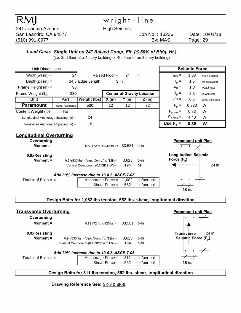
Wrightline241 Joaquin Avenue High SeismicSan Leandro, CA 94577 Job No. : 13236 Date: 10/01/13(510) 991-0977 By: MAS Page: 29
Load Case:(i.e. 2nd floor of a 4 story building or 4th floor of an 8 story building)
Width(w) (in) = 24 24 in SDS = 1.83 High Seismic
Depth(D) (in) = 34.5 Edge Length 3 in Ip = 1.5 (Importance)
Frame Height (in) = 96 ap = 1.0 (Cabinets)
Frame Weight (lb) = 230 Rp = 2.5 (Cabinets)
Unit Part Weight (lbs) X (in) Y (in) Z (in) z/h = 0.5 (50% of bldg ht.)
Paramount Frame +Contents 530 12 12 72 Fp = 0.880 W
Content Weight (lb) 300 Fp,min = 0.83 W
Longitudinal Anchorage Spacing (in) = 24 Fp,max = 4.40 W
Transverse Anchorage Spacing (in) = 18 Use Fp = 0.88 W
Longitudinal OverturningOverturning
Moment = 0.88 (72 in. x 530lbs.) = 33,581 lb-in
0.9xResistingMoment = 0 9 [(530 lbs Vert Comp ) x (12in)]= 3 625 lb-in
Center of Gravity Location
Paramount unit Plan
Single Unit on 24" Raised Comp. Flr. ( ≤ 50% of Bldg. Ht.)
Unit Dimensions Seismic Force
Raised Floor =
Longitudinal Seismic Force (Fp)Moment = 0.9 [(530 lbs. - Vert. Comp.) x (12in)]= 3,625 lb-in
194 lbs 24 in.
Add 30% increase due to 13.4.2. ASCE-7-05Total # of Bolts = 4 1,082 lbs/per bolt
552 lbs/per bolt18 in.
Transverse OverturningOverturning
Moment = 0.88 (72 in. x 530lbs.) = 33,581 lb-in
0.9xResisting 24 in.Moment = 0.9 [(530 lbs. - Vert. Comp.) x (12in.)]= 3,625 lb-in
194 lb-in
Add 30% increase due to 13.4.2. ASCE-7-05Total # of Bolts = 4 Anchorage Force = 811 lbs/per bolt
Shear Force = 552 lbs/per bolt 18 in.
SK-3 & SK-8
Vertical Component (0.2*SDS*Wp*12in) =
Drawing Reference See:
Shear Force =
Vertical Component (0.2*SDS*Wp) =
Anchorage Force =
Design Bolts for 811 lbs tension, 552 lbs. shear, longitudinal direction
Design Bolts for 1,082 lbs tension, 552 lbs. shear, longitudinal direction
Paramount unit Plan
Force (Fp)
TransverseSeismic Force (Fp)

Wrightline241 Joaquin Avenue High SeismicSan Leandro, CA 94577 Job No. : 13236 Date: 10/01/13(510) 991-0977 By: MAS Page: 30
Load Case: Ganged Unit (≤ 50% of Bldg. Ht.)
# of Units ganged (min)= 3
SDS = 1.83 High Seismic
Width(w) (in) = 24 Edge Length 3 in Ip = 1.5 (Importance)
Depth(D) (in) = 34.5 ap = 1.0 (Cabinets)
Frame Height (in) = 96 Rp = 2.5 (Cabinets)
Unit Weight (lb.) = 230 z/h = 0.5 (50% of bldg ht.)
Unit Part Weight (lbs) X (in) Y (in) Z (in) Fp = 0.880 W
3 - Paramount Frame +Contents 2,790 21 12 48 Fp,min = 0.83 W
Content Weight (lb) 700 Fp,max = 4.40 W
Longitudinal Anchorage Spacing (in) = 24 Use Fp = 0.88 WTransverse Anchorage Spacing (in) = 57
Longitudinal OverturningOverturning
Moment = 0.88 (96/2 in. x 2790lbs.) = 117,850 lb-in
0 9xResisting
Center of Gravity Location
Single Unit Dimension
Seismic Force
Ganged Paramount unit PlanLongitudinal Seismic Force
0.9xResistingMoment = 0.9 [(2790 lbs. - Vert. Comp.) x21 in.]= 33,396 lb-in
1,023 lbs
Add 30% increase due to 13.4.2. ASCE-7-05 3 ganged unitsAnchorage Force = 482 lbs
Shear Force = 761 lbs/per bolt # of bolts per unit = 4
Transverse OverturningOverturning
Moment = 0.88 (96/2 in. x 2790lbs.) = 117,850 lb-in
0.9xResistingMoment = 0.9 [(2790 lbs - Vert. Comp.) x12 in.] = 19,084 lb-in
1,023 lbs
Add 30% increase due to 13.4.2. ASCE-7-05 3 ganged unitsAnchorage Force = 892 lbs/per bolt # of bolts per unit = 4
Shear Force = 532 lbs/per bolt
Vertical Component (0.2*SDS*Wp) =
Vertical Component (0.2*SDS*Wp) =
Design Bolts for 892 lbs tension, 532 lbs. shear, longitudinal direction
SK-4 & SK-7
Design Bolts for 482 lbs tension, 761 lbs. shear, longitudinal direction
Ganged Paramount unit Plan
Drawing Reference See:
Transverse Seismic Force
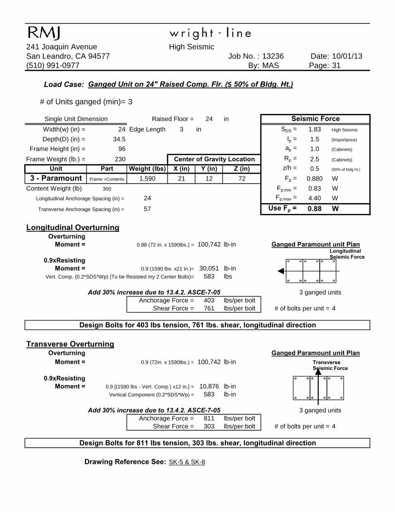
Wrightline241 Joaquin Avenue High SeismicSan Leandro, CA 94577 Job No. : 13236 Date: 10/01/13(510) 991-0977 By: MAS Page: 31
Load Case:
# of Units ganged (min)= 3
24 in
Width(w) (in) = 24 Edge Length 3 in SDS = 1.83 High Seismic
Depth(D) (in) = 34.5 Ip = 1.5 (Importance)
Frame Height (in) = 96 ap = 1.0 (Cabinets)
Frame Weight (lb.) = 230 Rp = 2.5 (Cabinets)
Unit Part Weight (lbs) X (in) Y (in) Z (in) z/h = 0.5 (50% of bldg ht.)
3 - Paramount Frame +Contents 1,590 21 12 72 Fp = 0.880 W
Content Weight (lb) 300 Fp,min = 0.83 W
Longitudinal Anchorage Spacing (in) = 24 Fp,max = 4.40 W
Transverse Anchorage Spacing (in) = 57 Use Fp = 0.88 W
Longitudinal OverturningOverturning
Moment = 0.88 (72 in. x 1590lbs.) = 100,742 lb-in
0.9xResisting
Single Unit Dimension
Center of Gravity Location
Raised Floor =
Ganged Unit on 24" Raised Comp. Flr. (≤ 50% of Bldg. Ht.)
Seismic Force
Ganged Paramount unit PlanLongitudinal Seismic Force
0.9xResistingMoment = 0.9 (1590 lbs. x21 in.)= 30,051 lb-in
583 lbs
Add 30% increase due to 13.4.2. ASCE-7-05 3 ganged unitsAnchorage Force = 403 lbs/per bolt
Shear Force = 761 lbs/per bolt # of bolts per unit = 4
Transverse OverturningOverturning
Moment = 0.9 (72in. x 1590lbs.) = 100,742 lb-in
0.9xResistingMoment = 0.9 [(1590 lbs - Vert. Comp.) x12 in.] = 10,876 lb-in
583 lb-in
Add 30% increase due to 13.4.2. ASCE-7-05 3 ganged unitsAnchorage Force = 811 lbs/per bolt
Shear Force = 303 lbs/per bolt # of bolts per unit = 4
SK-5 & SK-8
Vert. Comp. (0.2*SDS*Wp) (To be Resisted my 2 Center Bolts)=
Drawing Reference See:
Design Bolts for 811 lbs tension, 303 lbs. shear, longitudinal direction
Ganged Paramount unit Plan
Vertical Component (0.2*SDS*Wp) =
Design Bolts for 403 lbs tension, 761 lbs. shear, longitudinal direction
Transverse Seismic Force

Robinson Meier Juilly & Associates
Drawing Details
Structural Engineers
Principals Peter Robinson, S.E. Jayson E. Haines, S.E.


www.hilti.us Profis Anchor 2.4.3
Input data and results must be checked for agreement with the existing conditions and for plausibility!PROFIS Anchor ( c ) 2003-2009 Hilti AG, FL-9494 Schaan Hilti is a registered Trademark of Hilti AG, Schaan
Company:Specifier:Address:Phone I Fax:E-Mail:
RMJ & AssociatesMario A. Sigala241 Joaquin Ave., San Leandro CA 94577510.991.0977 | [email protected]
Page:Project:Sub-Project I Pos. No.:Date:
1Wright Linemas9/30/2013
Specifier's comments: 13236-Shear
1 Input dataAnchor type and diameter: Kwik Bolt TZ - CS 1/2 (2)
Effective embedment depth: hef = 2.000 in., hnom = 2.375 in.
Material: Carbon Steel
Evaluation Service Report: ESR-1917
Issued I Valid: 5/1/2013 | 5/1/2015
Proof: design method ACI 318 / AC193
Stand-off installation: - (Recommended plate thickness: not calculated)
Profile: no profile
Base material: cracked concrete, 2500, fc' = 2500 psi; h = 4.000 in.
Reinforcement: tension: condition B, shear: condition B; no supplemental splitting reinforcement present
edge reinforcement: none or < No. 4 barSeismic loads (cat. C, D, E, or F) yes (D.3.3.6)
Geometry [in.] & Loading [lb, in.lb]
www.hilti.us Profis Anchor 2.4.3
Input data and results must be checked for agreement with the existing conditions and for plausibility!PROFIS Anchor ( c ) 2003-2009 Hilti AG, FL-9494 Schaan Hilti is a registered Trademark of Hilti AG, Schaan
Company:Specifier:Address:Phone I Fax:E-Mail:
RMJ & AssociatesMario A. Sigala241 Joaquin Ave., San Leandro CA 94577510.991.0977 | [email protected]
Page:Project:Sub-Project I Pos. No.:Date:
2Wright Linemas9/30/2013
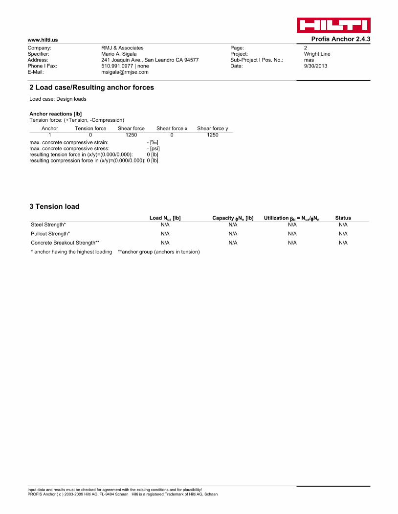
2 Load case/Resulting anchor forcesLoad case: Design loads
Anchor reactions [lb]Tension force: (+Tension, -Compression)
Anchor Tension force Shear force Shear force x Shear force y 1 0 1250 0 1250
max. concrete compressive strain: - [‰]max. concrete compressive stress: - [psi]resulting tension force in (x/y)=(0.000/0.000): 0 [lb]resulting compression force in (x/y)=(0.000/0.000): 0 [lb]
3 Tension load Load Nua [lb] Capacity ffffNn [lb] Utilization bbbbN = Nua/ffffNn Status Steel Strength* N/A N/A N/A N/A
Pullout Strength* N/A N/A N/A N/A
Concrete Breakout Strength** N/A N/A N/A N/A
* anchor having the highest loading **anchor group (anchors in tension)

www.hilti.us Profis Anchor 2.4.3
Input data and results must be checked for agreement with the existing conditions and for plausibility!PROFIS Anchor ( c ) 2003-2009 Hilti AG, FL-9494 Schaan Hilti is a registered Trademark of Hilti AG, Schaan
Company:Specifier:Address:Phone I Fax:E-Mail:
RMJ & AssociatesMario A. Sigala241 Joaquin Ave., San Leandro CA 94577510.991.0977 | [email protected]
Page:Project:Sub-Project I Pos. No.:Date:
3Wright Linemas9/30/2013
4 Shear load Load Vua [lb] Capacity ffffVn [lb] Utilization bbbbV = Vua/ffffVn Status Steel Strength* 1250 3572 35 OK
Steel failure (with lever arm)* N/A N/A N/A N/A
Pryout Strength** 1250 1262 100 OK
Concrete edge failure in direction y+** 1250 4479 28 OK
* anchor having the highest loading **anchor group (relevant anchors)
4.1 Steel Strength
Vseis = ESR value refer to ICC-ES ESR-1917f Vsteel ≥ Vua ACI 318-08 Eq. (D-2)
Variables n Ase,V [in.2] futa [psi] 1 0.10 106000
Calculations Vsa [lb]
5495
Results Vsa [lb] fsteel f Vsa [lb] Vua [lb]
5495 0.650 3572 1250
4.2 Pryout Strength
Vcp = kcp [(ANcANc0
) yed,N yc,N ycp,N Nb] ACI 318-08 Eq. (D-30)
f Vcp ≥ Vua ACI 318-08 Eq. (D-2)ANc see ACI 318-08, Part D.5.2.1, Fig. RD.5.2.1(b) ANc0 = 9 h2
ef ACI 318-08 Eq. (D-6)
yec,N = ( 1
1 + 2 e'N
3 hef) ≤ 1.0 ACI 318-08 Eq. (D-9)
yed,N = 0.7 + 0.3 ( ca,min1.5hef
) ≤ 1.0 ACI 318-08 Eq. (D-11)
ycp,N = MAX(ca,mincac
, 1.5hefcac
) ≤ 1.0 ACI 318-08 Eq. (D-13)
Nb = kc l √f'c h1.5ef ACI 318-08 Eq. (D-7)
Variables kcp hef [in.] ec1,N [in.] ec2,N [in.] ca,min [in.]
1 2.000 0.000 0.000 24.000
yc,N cac [in.] kc l f'c [psi] 1.000 5.500 17 1 2500
Calculations ANc [in.2] ANc0 [in.2] yec1,N yec2,N yed,N ycp,N Nb [lb]
36.00 36.00 1.000 1.000 1.000 1.000 2404
Results Vcp [lb] fconcrete fseismic fnonductile f Vcp [lb] Vua [lb]
2404 0.700 0.750 1.000 1262 1250

www.hilti.us Profis Anchor 2.4.3
Input data and results must be checked for agreement with the existing conditions and for plausibility!PROFIS Anchor ( c ) 2003-2009 Hilti AG, FL-9494 Schaan Hilti is a registered Trademark of Hilti AG, Schaan
Company:Specifier:Address:Phone I Fax:E-Mail:
RMJ & AssociatesMario A. Sigala241 Joaquin Ave., San Leandro CA 94577510.991.0977 | [email protected]
Page:Project:Sub-Project I Pos. No.:Date:
4Wright Linemas9/30/2013
4.3 Concrete edge failure in direction y+
Vcb = (AVcAVc0
) yed,V yc,V yh,V yparallel,V Vb ACI 318-08 Eq. (D-21)
f Vcb ≥ Vua ACI 318-08 Eq. (D-2)AVc see ACI 318-08, Part D.6.2.1, Fig. RD.6.2.1(b) AVc0 = 4.5 c2
a1 ACI 318-08 Eq. (D-23)
yec,V = ( 1
1 + 2e'v
3ca1) ≤ 1.0 ACI 318-08 Eq. (D-26)
yed,V = 0.7 + 0.3( ca21.5ca1
) ≤ 1.0 ACI 318-08 Eq. (D-28)
yh,V = √1.5ca1ha
≥ 1.0 ACI 318-08 Eq. (D-29)
Vb = (7 ( leda)0.2
√da) l √f'c c1.5a1 ACI 318-08 Eq. (D-24)
Variables ca1 [in.] ca2 [in.] ecV [in.] yc,V ha [in.] 16.000 24.000 0.000 1.000 4.000
le [in.] l da [in.] f'c [psi] yparallel,V 2.000 1.000 0.500 2500 1.000
Calculations AVc [in.2] AVc0 [in.2] yec,V yed,V yh,V Vb [lb]
192.00 1152.00 1.000 1.000 2.449 20900
Results Vcb [lb] fconcrete fseismic fnonductile f Vcb [lb] Vua [lb]
8532 0.700 0.750 1.000 4479 1250
5 Warnings• To avoid failure of the anchor plate the required thickness can be calculated in PROFIS Anchor. Load re-distributions on the anchors due to
elastic deformations of the anchor plate are not considered. The anchor plate is assumed to be sufficiently stiff, in order not to be deformed when subjected to the loading!
• Condition A applies when supplementary reinforcement is used. The Φ factor is increased for non-steel Design Strengths except Pullout Strength and Pryout strength. Condition B applies when supplementary reinforcement is not used and for Pullout Strength and Pryout Strength. Refer to your local standard.
• Refer to the manufacturer's product literature for cleaning and installation instructions.
• Checking the transfer of loads into the base material and the shear resistance are required in accordance with ACI 318 or the relevant standard!
• An anchor design approach for structures assigned to Seismic Design Category C, D, E or F is given in ACI 318-08 Appendix D, Part D.3.3.4 that requires the governing design strength of an anchor or group of anchors be limited by ductile steel failure. If this is NOT the case, Part D.3.3.5 requires that the attachment that the anchor is connecting to the structure shall be designed so that the attachment will undergo ductile yielding at a load level corresponding to anchor forces no greater than the controlling design strength. In lieu of D.3.3.4 and D.3.3.5, the minimum design strength of the anchors shall be multiplied by a reduction factor per D.3.3.6. An alternative anchor design approach to ACI 318-08, Part D.3.3 is given in IBC 2009, Section 1908.1.9. This approach contains "Exceptions" that may be applied in lieu of D.3.3 for applications involving "non-structural components" as defined in ASCE 7, Section 13.4.2. An alternative anchor design approach to ACI 318-08, Part D.3.3 is given in IBC 2009, Section 1908.1.9. This approach contains "Exceptions" that may be applied in lieu of D.3.3 for applications involving "wall out-of-plane forces" as defined in ASCE 7, Equation 12.11-1 or Equation 12.14-10.
• It is the responsibility of the user when inputting values for brittle reduction factors (fnonductile) different than those noted in ACI 318-08, Part D.3.3.6 to determine if they are consistent with the design provisions of ACI 318-08, ASCE 7 and the governing building code. Selection of fnonductile = 1.0 as a means of satisfying ACI 318-08, Part D.3.3.5 assumes the user has designed the attachment that the anchor is connecting to undergo ductile yielding at a force level <= the design strengths calculated per ACI 318-08, Part D.3.3.3.

www.hilti.us Profis Anchor 2.4.3
Input data and results must be checked for agreement with the existing conditions and for plausibility!PROFIS Anchor ( c ) 2003-2009 Hilti AG, FL-9494 Schaan Hilti is a registered Trademark of Hilti AG, Schaan
Company:Specifier:Address:Phone I Fax:E-Mail:
RMJ & AssociatesMario A. Sigala241 Joaquin Ave., San Leandro CA 94577510.991.0977 | [email protected]
Page:Project:Sub-Project I Pos. No.:Date:
1Wright Linemas9/30/2013
Specifier's comments: 13236-Tension
1 Input dataAnchor type and diameter: Kwik Bolt TZ - CS 1/2 (2)
Effective embedment depth: hef = 2.000 in., hnom = 2.375 in.
Material: Carbon Steel
Evaluation Service Report: ESR-1917
Issued I Valid: 5/1/2013 | 5/1/2015
Proof: design method ACI 318 / AC193
Stand-off installation: - (Recommended plate thickness: not calculated)
Profile: no profile
Base material: cracked concrete, 2500, fc' = 2500 psi; h = 4.000 in.
Reinforcement: tension: condition B, shear: condition B; no supplemental splitting reinforcement present
edge reinforcement: none or < No. 4 barSeismic loads (cat. C, D, E, or F) yes (D.3.3.6)
Geometry [in.] & Loading [lb, in.lb]
www.hilti.us Profis Anchor 2.4.3
Input data and results must be checked for agreement with the existing conditions and for plausibility!PROFIS Anchor ( c ) 2003-2009 Hilti AG, FL-9494 Schaan Hilti is a registered Trademark of Hilti AG, Schaan
Company:Specifier:Address:Phone I Fax:E-Mail:
RMJ & AssociatesMario A. Sigala241 Joaquin Ave., San Leandro CA 94577510.991.0977 | [email protected]
Page:Project:Sub-Project I Pos. No.:Date:
2Wright Linemas9/30/2013
2 Load case/Resulting anchor forcesLoad case: Design loads
Anchor reactions [lb]Tension force: (+Tension, -Compression)
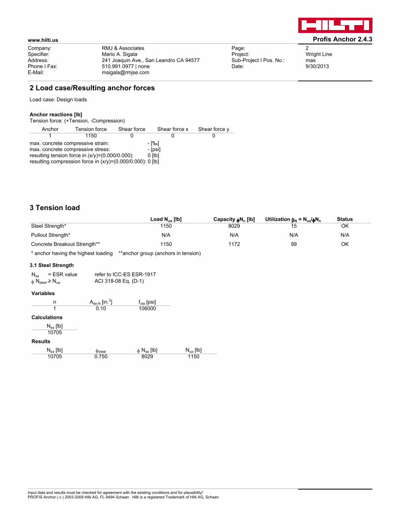
Anchor Tension force Shear force Shear force x Shear force y 1 1150 0 0 0
max. concrete compressive strain: - [‰]max. concrete compressive stress: - [psi]resulting tension force in (x/y)=(0.000/0.000): 0 [lb]resulting compression force in (x/y)=(0.000/0.000): 0 [lb]
3 Tension load Load Nua [lb] Capacity ffffNn [lb] Utilization bbbbN = Nua/ffffNn Status Steel Strength* 1150 8029 15 OK
Pullout Strength* N/A N/A N/A N/A
Concrete Breakout Strength** 1150 1172 99 OK
* anchor having the highest loading **anchor group (anchors in tension)
3.1 Steel Strength
Nsa = ESR value refer to ICC-ES ESR-1917f Nsteel ≥ Nua ACI 318-08 Eq. (D-1)
Variables n Ase,N [in.2] futa [psi] 1 0.10 106000
Calculations Nsa [lb]
10705
Results Nsa [lb] fsteel f Nsa [lb] Nua [lb]
10705 0.750 8029 1150

www.hilti.us Profis Anchor 2.4.3
Input data and results must be checked for agreement with the existing conditions and for plausibility!PROFIS Anchor ( c ) 2003-2009 Hilti AG, FL-9494 Schaan Hilti is a registered Trademark of Hilti AG, Schaan
Company:Specifier:Address:Phone I Fax:E-Mail:
RMJ & AssociatesMario A. Sigala241 Joaquin Ave., San Leandro CA 94577510.991.0977 | [email protected]
Page:Project:Sub-Project I Pos. No.:Date:
3Wright Linemas9/30/2013
3.2 Concrete Breakout Strength
Ncb = (ANcANc0
) yed,N yc,N ycp,N Nb ACI 318-08 Eq. (D-4)
f Ncb ≥ Nua ACI 318-08 Eq. (D-1)ANc see ACI 318-08, Part D.5.2.1, Fig. RD.5.2.1(b) ANc0 = 9 h2
ef ACI 318-08 Eq. (D-6)
yec,N = ( 1
1 + 2 e'N
3 hef) ≤ 1.0 ACI 318-08 Eq. (D-9)
yed,N = 0.7 + 0.3 ( ca,min1.5hef
) ≤ 1.0 ACI 318-08 Eq. (D-11)
ycp,N = MAX(ca,mincac
, 1.5hefcac
) ≤ 1.0 ACI 318-08 Eq. (D-13)
Nb = kc l √f'c h1.5ef ACI 318-08 Eq. (D-7)
Variables hef [in.] ec1,N [in.] ec2,N [in.] ca,min [in.] yc,N
2.000 0.000 0.000 24.000 1.000
cac [in.] kc l f'c [psi] 5.500 17 1 2500
Calculations ANc [in.2] ANc0 [in.2] yec1,N yec2,N yed,N ycp,N Nb [lb]
36.00 36.00 1.000 1.000 1.000 1.000 2404
Results Ncb [lb] fconcrete fseismic fnonductile f Ncb [lb] Nua [lb]
2404 0.650 0.750 1.000 1172 1150

www.hilti.us Profis Anchor 2.4.3
Input data and results must be checked for agreement with the existing conditions and for plausibility!PROFIS Anchor ( c ) 2003-2009 Hilti AG, FL-9494 Schaan Hilti is a registered Trademark of Hilti AG, Schaan
Company:Specifier:Address:Phone I Fax:E-Mail:
RMJ & AssociatesMario A. Sigala241 Joaquin Ave., San Leandro CA 94577510.991.0977 | [email protected]
Page:Project:Sub-Project I Pos. No.:Date:
4Wright Linemas9/30/2013
4 Shear load Load Vua [lb] Capacity ffffVn [lb] Utilization bbbbV = Vua/ffffVn Status Steel Strength* N/A N/A N/A N/A
Steel failure (with lever arm)* N/A N/A N/A N/A
Pryout Strength* N/A N/A N/A N/A
Concrete edge failure in direction ** N/A N/A N/A N/A
* anchor having the highest loading **anchor group (relevant anchors)
5 Warnings• To avoid failure of the anchor plate the required thickness can be calculated in PROFIS Anchor. Load re-distributions on the anchors due to
elastic deformations of the anchor plate are not considered. The anchor plate is assumed to be sufficiently stiff, in order not to be deformed when subjected to the loading!
• Condition A applies when supplementary reinforcement is used. The Φ factor is increased for non-steel Design Strengths except Pullout Strength and Pryout strength. Condition B applies when supplementary reinforcement is not used and for Pullout Strength and Pryout Strength. Refer to your local standard.
• Refer to the manufacturer's product literature for cleaning and installation instructions.
• Checking the transfer of loads into the base material and the shear resistance are required in accordance with ACI 318 or the relevant standard!
• An anchor design approach for structures assigned to Seismic Design Category C, D, E or F is given in ACI 318-08 Appendix D, Part D.3.3.4 that requires the governing design strength of an anchor or group of anchors be limited by ductile steel failure. If this is NOT the case, Part D.3.3.5 requires that the attachment that the anchor is connecting to the structure shall be designed so that the attachment will undergo ductile yielding at a load level corresponding to anchor forces no greater than the controlling design strength. In lieu of D.3.3.4 and D.3.3.5, the minimum design strength of the anchors shall be multiplied by a reduction factor per D.3.3.6. An alternative anchor design approach to ACI 318-08, Part D.3.3 is given in IBC 2009, Section 1908.1.9. This approach contains "Exceptions" that may be applied in lieu of D.3.3 for applications involving "non-structural components" as defined in ASCE 7, Section 13.4.2. An alternative anchor design approach to ACI 318-08, Part D.3.3 is given in IBC 2009, Section 1908.1.9. This approach contains "Exceptions" that may be applied in lieu of D.3.3 for applications involving "wall out-of-plane forces" as defined in ASCE 7, Equation 12.11-1 or Equation 12.14-10.
• It is the responsibility of the user when inputting values for brittle reduction factors (fnonductile) different than those noted in ACI 318-08, Part D.3.3.6 to determine if they are consistent with the design provisions of ACI 318-08, ASCE 7 and the governing building code. Selection of fnonductile = 1.0 as a means of satisfying ACI 318-08, Part D.3.3.5 assumes the user has designed the attachment that the anchor is connecting to undergo ductile yielding at a force level <= the design strengths calculated per ACI 318-08, Part D.3.3.3.
Fastening meets the design criteria!

APC by Schneider Electric
ARDC100
09222

APC by Schneider Electric
ARDC100
09222

APC by Schneider Electric
ARDC100
09222


![34007776 AD (web)[1]lit.powerware.com/ll_download.asp?file=Eaton EX - 2200_RT_2U-2200... · (24) Bouton d’abandon, de retour (25) Bouton de défilement (26) Bouton de validation](https://img.dokumen.tips/doc/110x75/5b90c27009d3f252108c8b12/34007776-ad-web1lit-ex-2200rt2u-2200-24-bouton-dabandon-de.jpg)