Embed Size (px)
Citation preview

Parametric Design and Optimization Analysis of Autoclave Based on UG and Workbench
Xuedong Liu*, Mingxing Du and Fan Qi School of Mechanical Engineering, Changzhou University, Changzhou Jiangsu 213164, China
*Corresponding author Abstract—The paper introduces the parametric design and assembly of autoclave with a nominal diameter of 4000 mm, which UG software is used in. Through establishment of a three-dimensional model of autoclave by UG software and the static analysis of the autoclave on the ANSYS Workbench platform, the stress distribution was obtained. While the wall thickness was optimized by iterate. Finally, the dangerous section of the model which wall thickness was optimized was linearized. The results show that the parametric modeling method improves the design, modeling and analysis of autoclave. Also, it reduces the wall thickness of autoclave.
Keywords-autoclave; parameterization; ANSYS Workbench; optimization
I. INTRODUCTION
Autoclave is also called the steaming kettle, widely used in autoclave curing of the concrete pipe pile, lime-sand brick, fly ash brick and aerated concrete block, the new light wall materials and other building materials products. It has several characteristics such as similar structure, bearing of large diameter, long length, and so on. Autoclaved kettle need frequent opening and closing during the process of using, inside the kettle with the temperature and pressure rise and drop, as in [1]. A slight error in the process of design, manufacture and use is likely to trigger a serious accident, so the research on design and analysis autoclave is particularly important. The traditional design of autoclave has long cycle and low efficiency. While the designer can use UG to realize fast of parametric design of autoclave and perform finite element analysis by the ANSYS Workbench, only need to modify the relevant parameters, so as to shorten the design work and improved the efficiency.
II. PARAMETRIC DESIGN OF AUTOCLAVE
ANSYS Workbench is a new collaborative environment of CAD/CAE. We can unify the CAD software modeling, assembly and the function of the parametric analysis with the analysis and post-processing of FEA solver in Workbench to share and exchange data. Also, we can optimize the important structure parameter, as in [2,3].
Predecessors always need to repeat the creation of three-dimensional model of autoclave when the finite element analysis was carried out on the working condition of each situation, as in [4]. That wastes a lot of unnecessary manpower and material resources. In contrast, the development cycle of parametric design is shorter and more efficient.
A. Parameter Settings
The research object of design parameters is as shown in table 1.
TABLE I. DESIGN PARAMETER TABLE
Parameter Value
The kettle body diameter Di[mm] 4000
The length of the container l[mm] 21000
Poisson's ratio μ 0.3
Corrosion allowance C[mm] 2
Design temperature T[℃] 200
Coefficient of welding joint φ 0.85
Design pressure Pc[MPa] 1.8
Pressure of work P[MPa] 1.6
Elastic modulus E[MPa] 2×10⁵
Density ρ[kg/m3] 7850
Design stress intensity of Q345R [MPa] 170
The material of Kettle body and kettle body flange is Q345R. Support material is Q235-A.
Autoclave includes body device, kettle, kettle cover device, fixed support, movable support, end support, and other components, as shown in figure 1.
1- kettle cover device;2- kettle body flange;3- kettle body device;4- fixed
support;5- movable support;6- end support;
FIGURE I. STRUCTURE DIAGRAM OF THE AUTOCLAVE
B. Parametric Modeling of Autoclave
Expression is an important object of UG model, is used to control the component characteristics of numerical or conditional statement, as in [5]. Expressions can define and control model of many dimensions, such as feature sizes or sketch dimension. Such as the thickness of the kettle body parts can be used to express its radius (wall thickness calculation formula of GB150). The thickness of the kettle shell will automatically update if the radius changes. Expression is a statement of defined relationship. Its essence is a pair of
International Conference on Artificial Intelligence: Technologies and Applications (ICAITA 2016)
© 2016. The authors - Published by Atlantis Press 345
relationship, such as "name = value". The right side is a numeric value, was assigned to the expressions of the left which is the name of the expression.
According to the relevance of the parameters, size will be mainly divided into three kinds of parameters, the main parameters, exported and independent parameters. The main parameters refer to the parameters plays a decisive role in the link of product design (such as the kettle body radius r). The exported parameters refer to the parameters calculated from other parameters (such as the kettle wall thickness T). The independent parameters refer to the parameters inputted in the design process according to the experience and intention of the designers (such as body length l).
The relationship of the main, exported, independence parameters and constraints of the autoclave is analyzed. It can realize the parametric modeling of every part of autoclave by listing the corresponding expressions and create new constraints according to need. The parameterized model of body of autoclave is shown in figure 2.
FIGURE II. CYLINDER PARAMETERIZED MODEL INTERFACE
After completing the parameterized modeling of every part of autoclaved kettle, assembled in turn. Then select an optimal drive size, we choose the radius of autoclaved kettle body flange size as the driver of the whole assembly. And then make full use of the expression between components to create components, associate every part by driving dimension. At last, this completes the parametric assembly of autoclave. For example, the designers can establish the associate between the radius of kettle body flange and kettle body when the kettle body to match the body flange. When the kettle body flange radius is modified, the kettle body radius automatically updated.
III. FINITE ELEMENT ANALYSIS AND OPTIMIZATION OF
AUTOCLAVE
A. Meshing
At different parts of autoclave different ways of meshing was adopted. The Sweep(scanning method) way to divide was adopted at the kettle body. There were 4 layer hexahedral grids in the radial direction. Grid refinement was adopted at kettle cover and kettle body flange. Here we choose the HEXA (hexahedron) mapping grid type and the grid size is 5 mm. There is 1222450 unites and 4998028 nodes. Skewness of grid (value of Skewness) with a mean of 0.15, the maximum value is 0.63, the grid quality is very good. The kettle body, the
cover and the body flange assembly drawing and local amplification figure as shown in figure 3(a), (b).
(a)
(b)
FIGURE III. MESHING DIAGRAM OF AUTOCLAVE
B. Applying Boundary Conditions and Solving
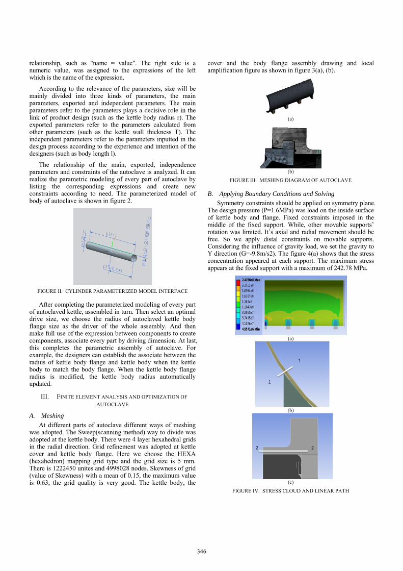
Symmetry constraints should be applied on symmetry plane. The design pressure (P=1.6MPa) was load on the inside surface of kettle body and flange. Fixed constraints imposed in the middle of the fixed support. While, other movable supports’ rotation was limited. It’s axial and radial movement should be free. So we apply distal constraints on movable supports. Considering the influence of gravity load, we set the gravity to Y direction (G=-9.8m/s2). The figure 4(a) shows that the stress concentration appeared at each support. The maximum stress appears at the fixed support with a maximum of 242.78 MPa.
(a)
(b)
(c)
FIGURE IV. STRESS CLOUD AND LINEAR PATH
346

C. Wall Thickness Optimization
After the completion of finite element analysis, the stress concentration position (path 1-1) and the connection of the kettle body and cover flange (path 2-2) was linearized respectively. The stress cloud and linear path as shown in figure 4(a), (b), (c). The membrane stress and bending stress, as shown in figure 5. The two groups of stress set for the output variable. The wall thickness computed by formulas in GB150 as the baseline. The iteration step length is 0.1 mm. The iteration result as shown in table 2. The membrane stress of the path 1-1 was primary local membrane stress P1. The membrane stress of the path 2-2 is primary local membrane stress and secondary bending stress P2 (P1<1.5Sm=255MPa, P2<3Sm=510MPa). The wall thickness was chosen when the value satisfied the P1 and P2.
From the table 2 we can realize that, with the increase of wall thickness, the value of P2 is far less than 510MPa and reduced gradually. When the wall thickness is 22.80mm the value of P1 has reached the requirements of allowable stress.
1-1
2-2
FIGURE V. LINEAR STRESS
TABLE II. ITERATIVE PROCESS OF THE OPTIMIZATION OF THE WALL THICKNESS
Iterative sequence
Design parametersThickness T (mm)
Output parameters Path 1-1 Path 2-2
P1max(MPa) P2max(MPa)
1 25.07 221.13 136.15
2 25.0 221.61 136.73
11 24.0 228.40 142.12
12 23.9 229.06 142.74
13 23.8 229.82 143.36
14 23.7 230.72 143.99
21 23.0 244.36 148.51
22 22.9 247.83 149.14
23 22.8 251.85 149.71
24 22.7 256.47 150.43
IV. STRESS EVALUATION OF PARAMETRIC DESIGN
OPTIMIZATION MODEL
The meshing and boundary condition are applied as chapter 3. Solving and outputting the primary stress and secondary stress of autoclave at the steady state operating conditions, as in [6]. The stress intensity equivalent cloud of kettle flange is shown in figure 6(a). The maximum stress intensity of meshing teeth of kettle cover flange appeared in the lateral position, about 637.84MPa. As shown in figure 6(b).
(a)
(b)
FIGURE VI. STRESS CLOUD OF KETTLE AND KETTLE FLANGE
347

FIGURE VII. STRESS EVALUATION LINE
Using the line processing method, assessed the stress on the dangerous section stress, according to the stress evaluation of line, selected as shown in figure 7. The evaluation conditions of stress intensity as follows:
TABLE III. STRESS INTENSITY EVALUATION OF EACH CLASSIFICATION LINE
The path
m
mP
S L
m1.5
P
S
m3mP Q
S
m3LP Q
S
m1.5m bP P
S
Evaluation
1-1 0.42 0.14 qualified
2-2 0.34 0.20 qualified
3-3 0.46 0.67 qualified
4-4 0.62 0.66 qualified
5-5 0.75 0.89 qualified
6-6 0.11 0.18 qualified
7-7 0.08 0.24 qualified
8-8 0.21 0.21 qualified
The stress intensity of the primary general thin film stress:
m m1.0P S
The stress intensity of the primary local thin film stress:
L m1.5P S
The primary stress intensity of the film (general or local) plus bending stress:
m b m+ 1.5P P S
The primary stress intensity plus secondary stress intensity:
m m+ 3.0P Q S
The result of each part of evaluating line is shown in table 3. Finally, we can see that each section can satisfy the conditions of the stress intensity.
V. CONCLUSIONS
(1) The method of combination of UG and ANSYS Workbench software was adopted. That realized the finite element design and analysis overall the parameterized autoclave. The overall coordination of the method is good. According to this method of autoclaved kettle design and analysis, the development cycle can be shorted, and the design efficiency will be improved.
(2)The wall thickness of autoclave with a nominal diameter of 4000 mm was optimized by iterate. The optimized thickness of 22.80 mm, compared with the calculated wall thickness reduced 2.27 mm. The wall thickness is reduced by 9.05%
(3) Stress classification method is used to judge the result of the design. The results show that the design of autoclave meeting related standards.
REFERENCES [1] Y. Fu, H. Huang and T. W. Liu, “Failure analysis on kettle tooth cracks of
large pressure vessel autoclave,” J. CHINA SPECIAL EQUIPMENT SAFETY, vol. 31(Z1), pp. 121-124, 2015.
[2] H. Feng, C. H. Li and L. He, “Suspension beam optimizing based on ansys workbench,” J. Modern Machinery, vol. 48(1), pp. 37-39, 2013.
[3] J. Zhang, H. Xu and W. R. Wang, “Pressure vessel thickness optimization design based on APDL,” J. Mechanical Engineering Automation, vol. 170(1), pp. 52-54, 2012.
[4] J. Y. Zheng, W. X. Su and P. Xu, “Unique design of tooth-locked quick closure pressure vessel based on the whole finite element stress analysis,” J. Pressure Vessel Technology, vol. 20(07), pp.20-24, 2003.
[5] W. H. Kuang., Z. Y. Xian and Y. H. Chen, “Construction principle and method of standard stamping part library based on UG,” J. Machinery Design & Manufacture, vol. (12), pp. 244-246, 2011.
[6] P. Liu, P. Xu and S. Han, “Optimal design of pressure vessel using an improved genetic algorithm,” J. Journal of Zhejiang University SCIENCE A, vol. (9), pp. 1264-1269, 2008.
348