Embed Size (px)
Citation preview

Parameter control scheme for active power filter based on NARX neural network
A. Y. HATATA, M. ELADAWY, K. SHEBL Department of Electric Engineering
Mansoura University Mansoura, EGYPT
[email protected] Abstract: - This paper presents a shunt active power filter control reference signal using Nonlinear Autoregressive with eXogenous neural network (NARX) with back propagation training algorithm. The instantaneous reactive power algorithm is integrated within the neural network to extract the dominant harmonics. The proposed method is demonstrated on three phase thyristor controlled drive which is one of widely used loads in petroleum industry field. Key-Words: - NARX Neural Network; Nonlinear Loads; Shunt Active Power Filter; Instantaneous Reactive Power Algorithm 1 Introduction
The rapid increase in electronic device technology cause industrial loads to become nonlinear and consequently results in significant level of harmonic distortion. Harmonic current drawn from the supply by the nonlinear loads results in the distortion of the supply voltage waveform at the point of common coupling (PCC) due to the source impedance. Harmonics generally are affected badly on utility and customer equipments. They may cause protection devices malfunction, increase power losses and line temperature and create noise and resonance [1].
Active Power Filter (APF) provides a solution of the problems of power quality such as reactive power compensation, harmonic mitigation and harmonic damping [2]. According to their topology active filters can be divided to shunt, series and unified or hybrid Active power filters [3]. Shunt active power filter is considered as the most popular topology of APFs. The main purpose of shunt active power filters is to compensate harmonics of load current [4-5].
Series active power filter is more suitable for harmonic voltage sources loads, the main purpose of this type of active filters is to compensate negative sequence voltage and regulate voltage in three phase system [6].
Unified power quality conditioner is a combination of series and shunt active filters and its function is to isolate voltage harmonics and current harmonics. This type of active power filter is expensive and complex in control [7]. Hybrid
active filter is raised up to reduce the initial cost of filtering, by using passive filter to tune up to the most dominant harmonic order and then connected with series or shunt active power filter. This will reduce active filter rating and cost in turn [8].
Many researchers interested in active power filters providing various types and classifications according to converter configuration, topology, application and control strategy. Ref [10] proposed systems that achieve isolation at the dominant harmonic frequencies for six pulses rectifier from ends using square wave inverters. The artificial neural network technique was used for the control of active power filter [9, 11]. NARX is one of the RNN schemes with global feedback. It considered as a time series forecasting networks [12]. It gives a dynamic responsibility, fast and accurate training response. NARX has a flexible architecture combining between simplicity (since it is simple to learn using backpropagation algorithms) and time series forecasting. The NARX is a perfect tool in simulating the complicated nonlinear systems because of its long term-dependencies and its computational power [13].
In this paper shunt active power filter is proposed as a solution of harmonic distortion. The main issue for active power filter is to find a control method which quickly obtains the compensation reference current with minimal errors. The control has two steps; the first one is to generate the control reference signals and the second step carries out the control method [2].
WSEAS TRANSACTIONS on POWER SYSTEMS A. Y. Hatata, M. Eladawy, K. Shebl
E-ISSN: 2224-350X 118 Volume 13, 2018

The control reference signal of shunt active power filter is proposed using NARX neural network with backpropagation training algorithm. The instantaneous reactive power algorithm is integrated with the neural network to extract the dominant harmonics. 2 Instantaneous Reactive Power Algorithm
This method is also named the p–q method. It was introduced for active filter applications by Akagi in 1984 [2]. The current and voltage of the system are converted into the αβ0 system using the following equations:
𝑖𝑖α𝑖𝑖 β𝑖𝑖0
= 23
1 2 30 √3
2−√3
21√2
1√2
1√2
𝑖𝑖𝑎𝑎𝑖𝑖𝑏𝑏𝑖𝑖𝑐𝑐
(1)
𝑣𝑣α𝑣𝑣 β𝑣𝑣0
= 23
1 2 30 √3
2−√3
21√2
1√2
1√2
𝑣𝑣𝑎𝑎𝑣𝑣 𝑏𝑏𝑣𝑣𝑐𝑐
(2) Based on p-q theory 𝑝𝑝 = 𝑣𝑣0𝑖𝑖0 + 𝑣𝑣𝑎𝑎𝑖𝑖𝑎𝑎 + 𝑣𝑣𝑏𝑏𝑖𝑖𝑏𝑏 (3) 𝑞𝑞 = 𝑣𝑣𝑎𝑎𝑖𝑖𝑎𝑎 − 𝑣𝑣𝑏𝑏𝑖𝑖𝑏𝑏
(4)
When the system is a symmetric three-phase or there is no neutral point
𝑝𝑝𝑞𝑞 =
𝑣𝑣α 𝑣𝑣β −𝑣𝑣β 𝑣𝑣α
𝑖𝑖α𝑖𝑖β (5)
The active and reactive power in Eq. 5 can be decomposed into two parts: AC and DC parts. The DC part resulted from the fundamental current and voltage and the AC part resulted from the harmonics.
𝑝𝑝 = 𝑝𝑝 + 𝑝𝑝 (6) 𝑞𝑞 = 𝑞𝑞 + 𝑞𝑞 (7)
𝑖𝑖α∗
𝑖𝑖β∗ = 1
𝑣𝑣α2 + 𝑣𝑣β2 𝑣𝑣α 𝑣𝑣β
−𝑣𝑣β 𝑣𝑣α 𝑝𝑝 + 𝑝𝑝𝑞𝑞 (8)
Where * denotes the reference value. These are reference values for the source currents. Therefore, the reference value for the active filter is as follows:
𝑖𝑖α𝐴𝐴𝐴𝐴∗ = 𝑖𝑖α∗ − 𝑖𝑖𝐿𝐿α
(9) 𝑖𝑖β𝐴𝐴𝐴𝐴∗ = 𝑖𝑖β∗ − 𝑖𝑖𝐿𝐿β
(10) The abc reference values for the active filter is
𝑖𝑖𝑎𝑎𝐴𝐴𝐴𝐴 ∗
𝑖𝑖𝑏𝑏𝐴𝐴𝐴𝐴 ∗
𝑖𝑖𝑐𝑐𝐴𝐴𝐴𝐴 ∗ = 2
3
⎣⎢⎢⎡ 1 0− 1
√2 √3
2
− 1√2
− √32 ⎦⎥⎥⎤𝑖𝑖α∗
𝑖𝑖β∗
(11) 3 NARX network architecture
In this paper a series parallel architecture of NARX will be used. This form combines between the features of feed-forward network and dynamic networks, thus the input to the feed-forward network is more accurate and the static back-propagation can be used for training [14-16]. The static back-propagation learning algorithm is applied to train the series parallel NARX network to identify the load model.
The final architecture of NARX network is achieved through a training procedure. Two hidden layers will be used in our proposed NARX neural network but the entire neurons will be changed according to the type of each load and the complexity of its waveforms. The training process will be tested for each load after changing the architecture of the NARX network from series-parallel to parallel by applying the actual measured voltage.
The field measured and simulated data are used to build the corresponding NARX network using the PCC supply voltage and the corresponding load currents. Each network will be tested with pure sinusoidal waveform and the resultant output will evaluate the true harmonics and nonlinearity of each load. The voltage waveforms will be used as a series-parallel NARX input, whereas the current waveforms will be used as the actual target, so that the training process can be applied faster and more accurate to each load.
WSEAS TRANSACTIONS on POWER SYSTEMS A. Y. Hatata, M. Eladawy, K. Shebl
E-ISSN: 2224-350X 119 Volume 13, 2018

Fig. 1 NARX network architecture The Fast Fourier Transform (FFT) technique
will be applied on the parallel NARX output and the results will be compared with the THD of actual measured current. If the THD of the parallel NARX output is the same as THD of the measured current, the training will be terminated as it gives a good result. The nonlinearity will appear for each load after making a good identification using parallel NARX architecture injected by mathematically generated sinusoidal waveform. The output will be tested again with FFT and the estimated THD will indicate the actual load nonlinearity after removing the PCC effects. The designed architecture is illustrated in Fig. 1. 4 NARX control reference Based Method for shunt active power filter
The NARX neural network based identifier is used to isolate the dominant harmonics from the rest of the current spectrum of a load. These isolated harmonics are then used with Instantaneous reactive power algorithm to mitigate the harmonics.
The PCC voltage and the non-linear load current are used to train the series parallel NARX network as the input and the target respectively. Then the NARX network will be converted to parallel NARX network so it will be injected with mathematically produced pure sinusoidal waveform.
The NARX output waveform and the pure sinusoidal voltage waveform will be used in p-q method to produce the true harmonics of the nonlinear load.
Fig. 2 The block diagram of NARX harmonics
extraction Fig. 2 shows the block diagram of NARX
harmonics extraction and Fig. 3 shows the evaluation of instantaneous P, Q using the pure sine waveform (Vsine) and NARX output waveform (Itrue).
Fig. 3 Block diagram of evaluation of instantaneous
P, Q using pure sine wave and corresponding NARX output
The instantaneous P, Q are used to evaluate Ialpha , Ibeta which represent the final step before evaluating reference current as illustrated in Fig.4.
NARX NARX
Measured V
Measured I
Trained Output
Measured V Tested Output
NARX
Pure Sine Wave Non-linearity Indication
output
FFT FFT
Measured THD = Tested THD
WSEAS TRANSACTIONS on POWER SYSTEMS A. Y. Hatata, M. Eladawy, K. Shebl
E-ISSN: 2224-350X 120 Volume 13, 2018

Fig. 4: Block diagram of reference current evaluation
The reference current are used to switch pulses to the power electronic elements GTO/Diodes to force the power converter to act as a current source to follow the reference current changes. 5 Result and discussion
The tested system consists of 50 Hz, 200 V, voltage source connected to nonlinear load 6-pusle converter system through (Y-Δ) transformer and 400 V dc, 5 Ω active filter through 20 KVA (Y-Y) transformer. Fig. 5 illustrate the single line diagram of the tested system.
Fig. 5 single line diagram of tested system
This case is applied using MATLAB
/SIMULINK environment as shown in fig. 6. The purpose of this case is to study the harmonic extraction and controlled power electronic converter using PWM to mitigate a certain level of harmonic
distortion using NARX. The nonlinear load current is shown in Fig. 7.
Fig. 6 MATLAB/SIMULINK model of the system
Fig.7 Nonlinear Load current
Fig. 8 FFT of nonlinear load current
Fig. 8 illustrates the FFT analysis of the load current which shows that THD of 18.53%. The load voltage waveform and load current which are used to train the three NARX networks using 17 neurons in each hidden layers using 1005 samples per cycle; the training data for the three phases are summarized in the fig. 9.
WSEAS TRANSACTIONS on POWER SYSTEMS A. Y. Hatata, M. Eladawy, K. Shebl
E-ISSN: 2224-350X 121 Volume 13, 2018

(a) Phase a
(b) Phase b
(c) Phase c
Fig. 9 Training performance for the three phases
The training procedure is applied using backprobagation algorithm. The performance data illustrate the advantage of NARX series parallel network as the best validation achieved very fast and with mean square error less than 10-6.
The fast performance of NARX series parallel network training procedure is suitable for the active power filter as it has a good response for the expected changes in waveforms. The comparison between the target waveform (nonlinear load current) and the NARX output using input voltage waveform is illustrated in Fig. 10.
Fig. 10 Comparison between parallel NARX output and target waveforms
In the next step, the NARX network will inject
by sinusoidal waveform which represent pure voltage source. The NARX output waveform and pure sinusoidal waveforms are used to evaluate the reference current using instantaneous reactive power technique as mentioned before. The instantaneous active and reactive power are illustrated in Fig. 11 and 12.
Fig. 11 Instantaneous Active Power Waveform
Fig. 12 Instantaneous Reactive Active Power
Waveform Fig. 13 illustrates the reference current for each
phase, thus it will be used as an input to 2 kHz PWM which will be used to firing 3 arms 6 pulses GTO/Diode to inject the active filter current to the network.
Fig. 13 reference current for each phase
WSEAS TRANSACTIONS on POWER SYSTEMS A. Y. Hatata, M. Eladawy, K. Shebl
E-ISSN: 2224-350X 122 Volume 13, 2018
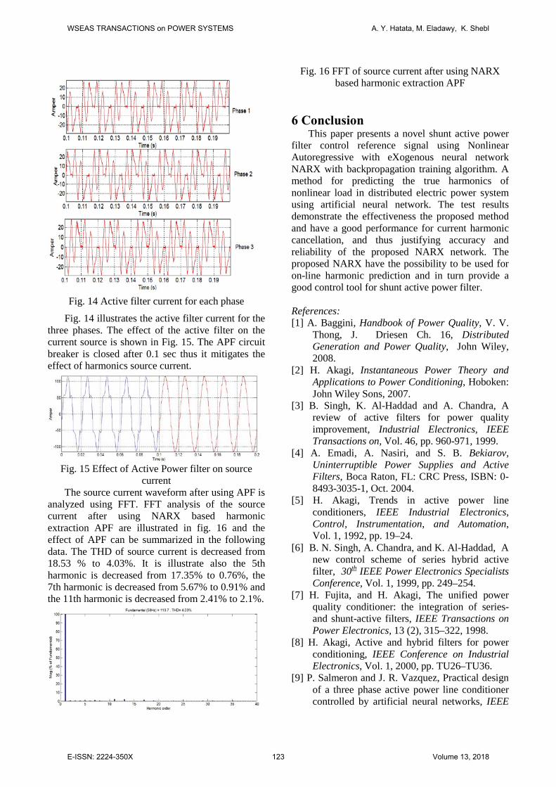
Fig. 14 Active filter current for each phase
Fig. 14 illustrates the active filter current for the three phases. The effect of the active filter on the current source is shown in Fig. 15. The APF circuit breaker is closed after 0.1 sec thus it mitigates the effect of harmonics source current.
Fig. 15 Effect of Active Power filter on source
current The source current waveform after using APF is
analyzed using FFT. FFT analysis of the source current after using NARX based harmonic extraction APF are illustrated in fig. 16 and the effect of APF can be summarized in the following data. The THD of source current is decreased from 18.53 % to 4.03%. It is illustrate also the 5th harmonic is decreased from 17.35% to 0.76%, the 7th harmonic is decreased from 5.67% to 0.91% and the 11th harmonic is decreased from 2.41% to 2.1%.
Fig. 16 FFT of source current after using NARX based harmonic extraction APF
6 Conclusion
This paper presents a novel shunt active power filter control reference signal using Nonlinear Autoregressive with eXogenous neural network NARX with backpropagation training algorithm. A method for predicting the true harmonics of nonlinear load in distributed electric power system using artificial neural network. The test results demonstrate the effectiveness the proposed method and have a good performance for current harmonic cancellation, and thus justifying accuracy and reliability of the proposed NARX network. The proposed NARX have the possibility to be used for on-line harmonic prediction and in turn provide a good control tool for shunt active power filter. References: [1] A. Baggini, Handbook of Power Quality, V. V.
Thong, J. Driesen Ch. 16, Distributed Generation and Power Quality, John Wiley, 2008.
[2] H. Akagi, Instantaneous Power Theory and Applications to Power Conditioning, Hoboken: John Wiley Sons, 2007.
[3] B. Singh, K. Al-Haddad and A. Chandra, A review of active filters for power quality improvement, Industrial Electronics, IEEE Transactions on, Vol. 46, pp. 960-971, 1999.
[4] A. Emadi, A. Nasiri, and S. B. Bekiarov, Uninterruptible Power Supplies and Active Filters, Boca Raton, FL: CRC Press, ISBN: 0-8493-3035-1, Oct. 2004.
[5] H. Akagi, Trends in active power line conditioners, IEEE Industrial Electronics, Control, Instrumentation, and Automation, Vol. 1, 1992, pp. 19–24.
[6] B. N. Singh, A. Chandra, and K. Al-Haddad, A new control scheme of series hybrid active filter, 30th IEEE Power Electronics Specialists Conference, Vol. 1, 1999, pp. 249–254.
[7] H. Fujita, and H. Akagi, The unified power quality conditioner: the integration of series- and shunt-active filters, IEEE Transactions on Power Electronics, 13 (2), 315–322, 1998.
[8] H. Akagi, Active and hybrid filters for power conditioning, IEEE Conference on Industrial Electronics, Vol. 1, 2000, pp. TU26–TU36.
[9] P. Salmeron and J. R. Vazquez, Practical design of a three phase active power line conditioner controlled by artificial neural networks, IEEE
WSEAS TRANSACTIONS on POWER SYSTEMS A. Y. Hatata, M. Eladawy, K. Shebl
E-ISSN: 2224-350X 123 Volume 13, 2018

Transactions on Power Delivery, Vol. 20, 2, pp.1037-1044, April 2005.
[10] P. Cheng, S. Bhattacharya and D. Divan, Experimental verification of dominant harmonic active filter for high power applications, IEEE Transactions on Industry Applications, Vol. 36, pp.567-577, March/April 2000.
[11] J. Mazumdar, System and method for determining harmonic contributions from nonlinear loads in power systems, Georgia Institute of Technology Dec. 2006.
[12] M. U. Hashmi, V. Arora, J. G. Priolkar, Hourly electric load forecasting using Nonlinear AutoRegressive with eXogenous (NARX) based neural network for the state of Goa, India, Industrial Instrumentation and Control (ICIC), 2015 International Conference on Year: 2015, Pp. 1418 - 1423, IEEE Conference Publications.
[13] Y. Liu, X. Wang, Y. Liu, Asynchronous harmonic analysis based on out-of-sequence measurement for large-scale residential power network, Instrumentation and Measurement Technology Conference (I2MTC), 2015, pp. 1693 – 1698, IEEE Conference Publications
[14] H. T. Siegelmann, and E. D. Sontag, Turing Computability with Neural Nets, Applied Mathematics Letters, Vol. 4, 1991, pp. 77-80.
[15] M. T. Hagan, H. B. Demuth, M. H. Beale, Neural Network Design, Jan 2002
[16] M. H. Beale, M. T. Hagan, H. B. Demuth, Neural Network Toolbox™ 7 User’s Guide.
WSEAS TRANSACTIONS on POWER SYSTEMS A. Y. Hatata, M. Eladawy, K. Shebl
E-ISSN: 2224-350X 124 Volume 13, 2018