Embed Size (px)
Citation preview
Research ArticleParameter Analysis on Wind-Induced Vibration of UHVCross-Rope Suspension Tower-Line
Xilai Li1 Dengke Yu1 and Zhengliang Li2
1The Electric Power Planning amp Engineering Institute Co Ltd Xicheng District Beijing 100120 China2The Civil Engineering Department University of Chongqing Shapingba District Chongqing 400045 China
Correspondence should be addressed to Dengke Yu dkyueppeicom
Received 6 December 2016 Accepted 24 January 2017 Published 16 February 2017
Academic Editor John Mander
Copyright copy 2017 Xilai Li et al This is an open access article distributed under the Creative Commons Attribution License whichpermits unrestricted use distribution and reproduction in any medium provided the original work is properly cited
This paper analyzes the influences of important structural design parameters on the wind-induced response of cross-ropesuspension tower-line A finite element model of cross-rope suspension tower-line system is established and the dynamic time-history analysis with harmonic wave superposition method is conducted The two important structural design parameters suchas initial guy pretension and sag-span ratio of suspension-rope are studied as well as their influences on the three wind-inducedvibration responses such as tensile force on guys the reaction force onmast supports and the along-wind displacement of the masttop the results show that the value of sag-span ratio of suspension-rope should not be less than 19 and the value of guy pretensionshould be less than 30 of its design bearing capacity On this occasion the tension in guys and compression in masts would bemaintained in smaller values which can lead to a much more reasonable structure
1 Introduction
The cross-rope suspension tower-line is similar in struc-ture to the hybrid structure in suspended cable system toprovide elastic support for the split conductors suspendedthrough insulators by using the cross-rope between the endsof double-mast and for setting up double-mast itself andmaintaining the load balance of entire tower it is necessaryto lay out guys at the two sides of the double-mast which asa tension structure system is of a complex nonlinear problemof which key structural design parameters include the initialguy pretension and the sag-span ratio of suspension-ropewhich will have a significant impact on the wind-inducedvibration response of the structure
Issa and Avent proposed discrete-field analysis methodand compiled related program for the analysis of guyedtowers [1] Ben Kahla proposed an approximate analysismethod of the guyed tower by simplifying guyed tower mastto equivalent curved beam [2] Sparling has put forward thatthe initial tensile force of guy-wires not only can providethe towers with wind direction stiffness but also will affectacross-wind stiffness and both are mutually coupled [3]
Madugula et al established the finite element programsimulating lattice mast with beam element used to studythe influence of the initial pretension of guys on structuredynamic response [4] Wahba et al discussed the finiteelement modeling method of two different guyed tower Oneis three-dimensional truss element modeling and the other iscurved beam element And it is shown by lots of numericalcalculation that the latter is more accurate [5] Kewaisyproposed hybrid mixed finite element model of guyed towersfor consideration of nonlinear effects [6] Desai and Pundeused the generalized finite element method to study thedynamic characteristics of suspension structure [7] Horr etal made nonlinear dynamic analysis by use of nonlinearfrequency domain analysis method [8] Meshmesha et alpresented an equivalent curved beam finite element methodto analyze the response characteristics of guyed towers understatic and dynamic loads and made the comparison withclassical finite element analysis method to verify the accuracyof the new method [9] Shi and De Oliveira et al also madethe relevant analysis of guyed towers using the finite elementmethod [10 11] Gani and Legeron analyzed two types ofguyed tower structures and pointed out that equivalent static
HindawiAdvances in Civil EngineeringVolume 2017 Article ID 8756019 9 pageshttpsdoiorg10115520178756019
2 Advances in Civil Engineering
Groundwire
Mast Mast
Steel-rope Conductor
InsulatorCross-rope
Groundwire
Groundwire
Conductor
Groundwire
GuysGuys
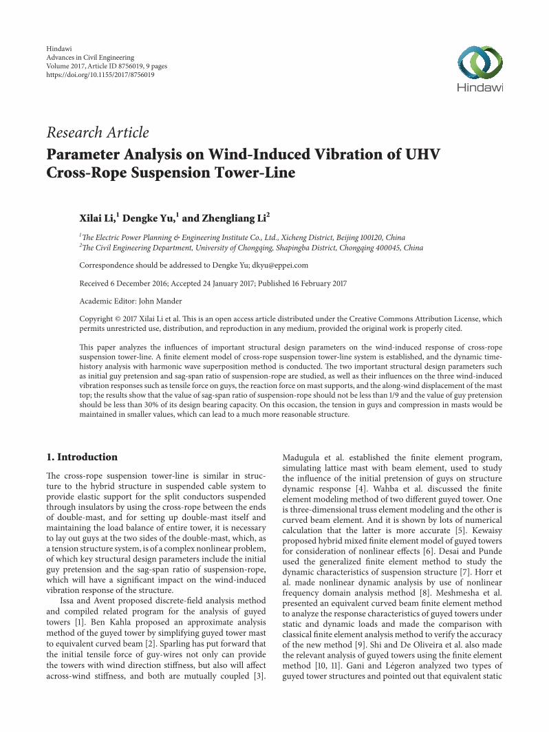
Figure 1 Schematic diagram of cross-rope suspension tower
method would underestimate the dynamic response of thetowers and proposed the simplified method which has beenimproved to more accurately estimate the dynamic effectof the towers [12] Ballaben et al carried out wind-inducedvibration analysis of several important design parameters ofguyed towers with results showing that the guy pretensionwas the most important variable influencing the tower topdisplacement of the towers [13] Carrasco-Luzardo et almadethe analysis of the tension of guyed mast in different initialtension conditions with the results showing that the naturalfrequency of the mast will increase with the increase ofthe initial tension [14] Wang et al set up the nonlinearfinite element model of single-mast guyed tower and studiedthe stress characteristic of single-mast guyed tower and theimpact of the initial guy pretension on it by static analysis andmade the time-history analysis of wind-induced vibrationresponse of tower-line system [15 16] And for study of cross-rope suspension tower-line at present only the author hasresearched the wind-induced vibration of it under differentguy pretensions and wind attack angles in wind tunnel test[17ndash20]
Therefore this paper focuses on the time-history analysisof wind-induced vibration of cross-rope suspension tower-line system so as to research the impact of the two importantdesign parameters namely initial guy pretension and the sag-span ratio of suspension-rope on thewind-induced vibrationcharacteristics of it The cross-rope suspension tower-line isshown in Figure 1
2 Finite Element Model of a Cross-RopeSuspension Tower-Line System
This paper aims at setting up the finite element modelof a cross-rope suspension tower which is recommended
Table 1 The material list of cross-rope suspension tower-line
Part name Weight (kg) Total (kg)Masts 2802164
3420254Steel-rope 2288Cross-rope 17269Guys 42252
in a UHV DC transmission line The tower is 54m highconductors are 6-split per phase with split spacing of 450mmand horizontal span of 480mThematerial list for cross-ropesuspension tower-line is as shown in Table 1 and the specificparameter statistics are as shown in Table 2
The main material for the double-mast is Q345 andQ235 single equal-angle steel During the finite elementmodeling BEAM188 beam element in ANSYS software wasused to simulate angle steel This type of beam elementis called 3D linear finite strain beam element suitable forthe problems such as linear large rotation and large strainproblems including stress stiffness so as to be able to makestability analysis the buckling analysis of characteristic valueof bending rolling motion torsion and so on BEAM188has two nodes with 6 to 7 free degrees 3 translational freedegrees 3 rotational free degrees and a warping free degreein cross section for each node
Guys suspension-rope and power transmission lineare all catenaries It is required to determine the initialconfiguration of the catenary in finite element modelingCatenary equation is not inconvenient to use due to itscomplexity to a certain extent in calculation so catenaryformula is generally simplified to parabolic formula andnamely approximately considering that line load is evenlydistributed along suspension point connection As shown in
Advances in Civil Engineering 3
Table 2 The parameter of cross-rope suspension tower-line
Part name Specification Calculation of sectional areamm2
Conductor JLG3A-100045 104538 (1043)Ground wire LBGJ-150-20AC 162877 (14807)Guy 1 times 37-280-1470-B 46495Suspension-rope 1 times 37-280-1470-B 46495Insulator 1000Steel-rope 1 times 19-50-1470-B 1492
Y998400
l
120590BV
120590B
1205900
B
y998400 Bh
l2
x998400
A
y998400 A
l0A l0B
120573
fm
f998400 X
y998400 X998400
Figure 2 Calculation diagram of inclined parabola
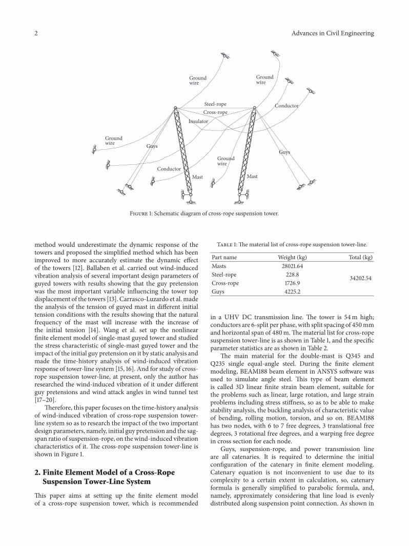
Figure 2 origin of coordinates is located at the suspensionpoint 119860
The curve equation of inclined parabola is shown in
1199101015840 = 1199091015840119905119892120573 minus 1205741199091015840 (119897 minus 1199091015840)21205900 cos120573 (1)
Sag formula is shown in
1198911015840119909 = 1205741199091015840 (119897 minus 1199091015840)21205900 cos120573 = 41199091015840119897 (1 minus 1199091015840119897 )119891119898 (2)
119891119898 = 120574119897281205900 cos120573 (3)
Span is shown in
119871 = 119897cos120573 + 12057421198973 cos1205732412059002 (4)
The comprehensive value of suspension point in stress tan-gential direction is shown in
120590119860 = radic12059020 + 12057421198972119874119860cos2120573
120590119861 = radic12059020 + 12057421198972119874119861cos2120573
(5)
4 Advances in Civil Engineering
0 200 400 600 800 1000minus20minus10
01020
Time (s)
Win
d sp
eed
(ms
)
Figure 3 Time-history curve of wind speed
Stress vertical component of the suspension point is shown in
120590119860119881 = 120574cos120573119897119874119860
120590119861119881 = 120574cos120573119897119874119861
(6)
Horizontal distance from the lowest point of parabola tosuspension point is shown in
119897119874119860 = 1198972 minus 1205900120574 sin120573119897119874119861 = 1198972 minus 1205900120574 sin120573
(7)
Vertical distance from the lowest point of parabola to suspen-sion point is shown in
119910119874119860(119874119861) = 119891119898 (1 plusmn ℎ4119891119898)2 (8)
Regarding the abovementioned equations l is span lengthℎ is height difference 120573 is the angle of height difference119891119898 is the maximum sag of parabola 1205900 is the horizontalstress of parabola at each point and 120574 is the relative load ofparabola (ie the load of unit length and unit cross section)The LINK180 bar element in ANSYS software can be usedto simulate catenary This kind of bar element is called 3Dfinite strain bar element being able to bear axial tension orcompression with the functions of plasticity creep rotationlarge deformation and large strain and so on also includingstress stiffening effect LINK180 unit has two nodes withthree translational free degrees on each node
3 Calculation Method ofWind-Induced Vibration
31 Simulation of Fluctuating Wind Field The method ofharmonic synthesis is used for numerical simulation with154 points of space fluctuating wind speed simulated in totalDavenport spectrum is adopted for wind speed spectrum andthe index coherence function proposed by Davenport is usedfor frequency domain coherence function Wind speed time-history curve and wind speed spectrum are shown in Figures3 and 4
32 Calculation Method of Finite Element The Newmarkmethod as implicit direct integral method is used to make
Simulation spectrumTarget spectrum
S(n
) (m
2s
)
1E minus 3
01
10
1000
001 01 11E minus 3
n (Hz)
Figure 4 Wind speed spectrum
time domain analysis of tower-line system for solution Itssolving process is briefly as follows
The motion equation for the structure within the time of119905 + Δ119905 is shown in
11987211988310158401015840119905+Δ119905 + 1198621198831015840119905+Δ119905 + 119870119883119905+Δ119905 = 119865119905+Δ119905 (9)
Provided that it is within the time domain of 119905 sim 119905 + Δ119905 thefollowing two formulas should be met
1198831015840119905+Δ119905 = 1198831015840119905 + [(1 minus 120575)11988310158401015840119905 + 12057511988310158401015840119905+Δ119905] Δ119905 (10)
119883119905+Δ119905 = 119883119905 + 1198831015840119905Δ119905+ [(12 minus 120572)11988310158401015840119905 + 12057211988310158401015840119905+Δ119905]Δ1199052
(11)
It can be gotten by formula (11)
11988310158401015840119905+Δ119905 = 1120572Δ1199052 (119883119905+Δ119905 minus 119883119905) minus 1120572Δ1199051198831015840119905minus ( 12120572 minus 1)11988310158401015840119905
(12)
Formula (12) is substituted into (10) and then merged intoformula (9) the two-step recursive formula for calculation of119883119905+Δ119905 according to1198831199051198831015840119905 and11988310158401015840119905 can be gotten
(119870 + 1120572Δ1199052119872+ 120575120572Δ119905119862)119883119905+Δ119905 = 119865119905+Δ119905+119872[ 1120572Δ1199052119883119905 + 1120572Δ1199051198831015840119905 + ( 12120572 minus 1)11988310158401015840119905]+ 119862[ 120575120572Δ119905119883119905 + (120575120572 minus 1)1198831015840119905 + ( 1205752120572 minus 1)Δ11990511988310158401015840119905]
(13)
Advances in Civil Engineering 5
WindDisplacement
at the top of mast on
leeward side
Guy tensile force on
windward side
Guy tensile
force on leeward
side
Reaction force on
mast support on leeward
side
Reaction force on mast
support on windward side
Displacementat the top of mast on windward
side
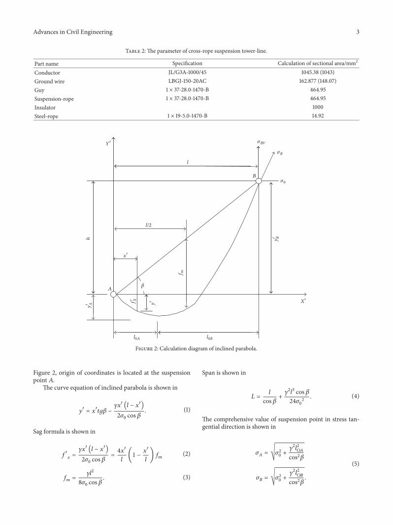
Figure 5 Results of response for parametric study
4 Parameter Analysis
The value size of the initial guy pretension plays a key rolein the overall stiffness and stability of the structure And thesuspension-rope as the carrier bearing insulator and splitconductors is the bridge to connect the masts at both sidesto realize internal force reconstruction
In order to study the influence of these two structuraldesign parameters the initial guy pretensions selectedin this paper are respectively 10 (7794Nmm2) 15(11691 Nmm2) 20 (15588Nmm2) 25 (19484Nmm2)30 (23381 Nmm2) 35 (27278Nmm2) and 40(31175Nmm2) of designed bearing capacity Sag-span ratiosof suspension-rope are chosen as 18 19 110 111 and 112 Itis required to analyze the cross-rope suspension tower-line inthe 0∘ working condition that coming wind is perpendicularto the direction of split conductors and select the guy tensileforce at both sides the reaction force on mast supports atboth sides and the displacement response at the top of mastsat both sides for parametric analysis as shown in Figure 5 inwhich wind speed is 33ms as designed
41 Influence of Tensile Force on Guys Figure 6 shows thesituation of the average value and the maximum valueof guy tensile force on both windward and leeward sidesvarying with the initial guy pretension and sag-span ratio ofsuspension-rope It can be seen from the figure that withthe increase of sag-span ratio the corresponding tensile forceaverage value and the maximum value of guys at both sidesshow a trend of decrease Under each sag-span ratio with theincrease of initial guy pretension the average value of tensileforce on guys at both sides basically increases linearly In the
case of the sag-span ratio of 18 and 19 the average value andmaximum value of tensile force are relatively smaller thanthose in the case of other sag-span ratios In the case of thesag-span ratio of 18 the maximum value of tensile force onguys on windward side gently changes with the increase ofinitial guy pretension and when the initial guy pretension isbetween 10 and 30 its value is relatively small After initialguy pretension is over 30 the maximum value of tensileforce on guys on leeward side increases evidently And in thecase of the sag-span ratio of 19 themaximum value of tensileforce on guys of both windward and leeward side increasesevidently after initial guy pretension is over 30 When sag-span ratio is relatively small namely 111 and 112 there is anevident nonlinear effect between the maximum value of guytensile force and the initial guy pretension on both sidesThismay be because different sag-span ratios of suspension-ropehave an important impact on the loaded property internalforce redistribution and so on
42 Influence of Reaction Force on Mast Support Figure 7shows the relational graph of the average value and themaximum value of reaction force on mast supports at bothsides varying with initial guy pretension and sag-span ratioof suspension-rope which is similar to the above-said changerule of tensile force on guys increasing with initial guypretension under each sag-span ratio with the average valueof reaction force on themast supports at both sides showing alinear growth trend when sag-span ratio is 18 themaximumvalue of reaction force on mast support on windward sideand leeward side is minimum At this point when initialguy pretension is greater than 30 the average value ofreaction force onmast support onwindward sidewill increasesignificantly
6 Advances in Civil Engineering
Sag-span ratio 18Sag-span ratio 19Sag-span ratio 110
Sag-span ratio 111Sag-span ratio 112
260
280
300
320
340
360
380
Aver
age v
alue
of g
uy te
nsile
forc
e (kN
)
15 20 25 30 35 4010Initial guy pretension ()
(a) Average value of guy tensile force on windward side
Sag-span ratio 18Sag-span ratio 19Sag-span ratio 110
Sag-span ratio 111Sag-span ratio 112
340
360
380
400
420
440
460
480
500
Max
imum
val
ue o
f guy
tens
ile fo
rce (
kN)
15 20 25 30 35 4010Initial guy pretension ()
(b) Maximum value of guy tensile force on windward side
Sag-span ratio 18Sag-span ratio 19Sag-span ratio 110
Sag-span ratio 111Sag-span ratio 112
60
80
100
120
140
160
180
Aver
age v
alue
of g
uy te
nsile
forc
e (kN
)
15 20 25 30 35 4010Initial guy pretension ()
(c) Average value of guy tensile force on leeward side
Sag-span ratio 18Sag-span ratio 19Sag-span ratio 110
Sag-span ratio 111Sag-span ratio 112
120
140
160
180
200
220
240
260
280M
axim
um v
alue
of g
uy te
nsile
forc
e (kN
)
15 20 25 30 35 4010Initial guy pretension ()
(d) Maximum value of guy tensile force on leeward side
Figure 6 Effect of initial guy pretension and sag-span ratio on guys
43 Influence of Displacement at the Top of Masts Figure 8shows the change situation of the average value and themaximum value of displacement on the top of masts at bothsides varying with the change of above-said two parametersAt this time it can be seen from the figure that withthe increase of sag-span ratio the average value and themaximum value of displacement on the top of masts onboth sides are increasing When sag-span ratio reaches 18the average value of displacement on the top of masts onboth sides on leeward side and the maximum value ofdisplacement on the top of mast on leeward side are largerthan the others With the increase of initial guy pretensionthe average value of displacement on the top of masts onboth sides decreases gradually while the maximum value of
displacement shows linear rule partially only when sag-spanratio is relatively small in general nonlinear effect is obvious
5 Further Discussion of Parameters
From the above analysis it is suggested that sag-span ratio ofsuspension-rope should be 18 or 19 so that the guy tensileforce and the reaction force on mast supports will be keptat a small value The displacement on the top of masts onboth sides will increase but effect is little due to very smalldisplacement value For the initial guy pretension accordingto code for high slender structure design for tower maststructure it is suggested that the initial guy pretension shouldbe selected in the range of 100sim250Nmm2 It is stipulated in
Advances in Civil Engineering 7
720
740
760
780
800
820
840
860Av
erag
e val
ue o
f rea
ctio
n fo
rce o
n su
ppor
t (kN
)
15 20 25 30 35 4010Initial guy pretension ()
Sag-span ratio 18Sag-span ratio 19Sag-span ratio 110
Sag-span ratio 111Sag-span ratio 112
(a) Average value of reaction force on support on windward side
15 20 25 30 35 4010Initial guy pretension ()
800
850
900
950
1000
1050
1100
Max
imum
val
ue o
f rea
ctio
n fo
rce o
n su
ppor
t(k
N)
Sag-span ratio 18Sag-span ratio 19Sag-span ratio 110
Sag-span ratio 111Sag-span ratio 112
(b) Maximum value of reaction force on support on windward side
340
360
380
400
420
440
460
480
500
Aver
age v
alue
of r
eact
ion
forc
e on
supp
ort (
kN)
15 20 25 30 35 4010Initial guy pretension ()
Sag-span ratio 18Sag-span ratio 19Sag-span ratio 110
Sag-span ratio 111Sag-span ratio 112
(c) Average value of reaction force on support on leeward side
450
500
550
600
650
Max
imum
val
ue o
f rea
ctio
n fo
rce o
n su
ppor
t(k
N)
15 20 25 30 35 4010Initial guy pretension ()
Sag-span ratio 18Sag-span ratio 19Sag-span ratio 110
Sag-span ratio 111Sag-span ratio 112
(d) Maximum value of reaction force on support on leeward side
Figure 7 Effect of initial guy pretension and sag-span ratio on masts
technical regulation of design for tower and pole structuresof overhead transmission line that the initial guy pretensionshould generally be controlled in 120sim140Nmm2 Accordingto the above analysis for the cross-rope suspension tower-line the initial guy pretension should be controlled within15 and 30 of designed bearing capacity
6 Conclusion
In cross-rope suspension tower-line system the initial guypretension and the sag-span ratio of suspension-rope asimportant structural design parameters will have a signifi-cant impact on wind-induced vibration response Therefore
this paper from the point of view of time domain analysishas made a variety of parameter analyses with the mainconclusions as follows
(1) It is advisable to take 18 or 19 for the sag-span ratio ofsuspension-rope which is used to connect the mastson both sides and provide elastic support for splitconductors so as to ensure making the guy tensileforce kept at a smaller value at the same time whenthe displacement on the top of masts is smaller
(2) Taking value for the initial guy pretension should becontrolledwithin 15 and 30of its designed bearingcapacity
8 Advances in Civil Engineering
Sag-span ratio 18Sag-span ratio 19Sag-span ratio 110
Sag-span ratio 111Sag-span ratio 112
0064
0066
0068
0070
0072
0074
0076
0078
0080Av
erag
e val
ue o
f disp
lace
men
t on
the t
op o
fm
ast (
m)
15 20 25 30 35 4010Initial guy pretension ()
(a) Average value of displacement on the top of mast on windward side
Sag-span ratio 18Sag-span ratio 19Sag-span ratio 110
Sag-span ratio 111Sag-span ratio 112
011
012
013
014
015
016
Max
imum
val
ue o
f disp
lace
men
t on
the t
op o
fm
ast (
m)
15 20 25 30 35 4010Initial guy pretension ()
(b) Maximum value of displacement on the top of mast on windwardside
Sag-span ratio 18Sag-span ratio 19Sag-span ratio 110
Sag-span ratio 111Sag-span ratio 112
15 20 25 30 35 4010Initial guy pretension ()
006
008
010
012
014
016
Aver
age v
alue
of d
ispla
cem
ent o
n th
e top
of
mas
t (m
)
(c) Average value of displacement on the top of mast on leeward side
Sag-span ratio 18Sag-span ratio 19Sag-span ratio 110
Sag-span ratio 111Sag-span ratio 112
15 20 25 30 35 4010Initial guy pretension ()
02
04
06
Max
imum
val
ue o
f disp
lace
men
t on
the t
op o
fm
ast (
m)
(d) Maximumvalue of displacement on the top ofmast on leeward side
Figure 8 Effect of initial guy pretension and sag-span ratio on masts
Competing Interests
The authors declare that there is no conflict of interestsregarding the publication of this paper
References
[1] R R A Issa and R R Avent ldquoMicrocomputer analysis of guyedtowers as latticesrdquo Journal of Structural Engineering vol 117 no4 pp 1238ndash1256 1991
[2] N Ben Kahla ldquoEquivalent beam-column analysis of guyedtowersrdquo Computers and Structures vol 55 no 4 pp 631ndash6451995
[3] B F Sparling The dynamic behavior of guys and guyed mastsin turbulent winds [PhD dissertation] University of WesternOntario London UK 1995
[4] M K S Madugula Y M F Wahba and G R MonfortonldquoDynamic response of guyedmastsrdquo Engineering Structures vol20 no 12 pp 1097ndash1101 1998
[5] Y M F Wahba M K S Madugula and G R MonfortonldquoEvaluation of non-linear analysis of guyed antenna towersrdquoComputers and Structures vol 68 no 1 pp 207ndash212 1998
[6] TH KewaisyNonlinear dynamic interaction between cables andmast of guyed-tower systems subjected to wind-induced forces[PhD thesis] Texas Tech University Lubbock Tex USA 2001
[7] Y M Desai and S Punde ldquoSimple model for dynamic analysisof cable supported structuresrdquo Engineering Structures vol 23no 3 pp 271ndash279 2001
[8] A M Horr A Yibulayin and P Disney ldquoNonlinear spectraldynamic analyis of guyed towers Part II manitoba towers casestudyrdquo Canadian Journal of Civil Engineering vol 31 no 6 pp1061ndash1076 2004
Advances in Civil Engineering 9
[9] H Meshmesha K Sennah and J B Kennedy ldquoSimple methodfor static and dynamic analyses of guyed towersrdquo StructuralEngineering and Mechanics vol 23 no 6 pp 635ndash649 2006
[10] H Shi Nonlinear finite element modeling and characterizationof guyed towers under severe loading [PhD thesis] University ofMissouri Columbia Mo USA 2007
[11] M I De Oliveira J G da Silba P C da Vellasco et al ldquoStruc-tural analysis of guyed steel telecommunication towers for radioantennasrdquo Journal of the Brazilian Society ofMechanical Sciencesand Engineering vol 29 no 2 pp 185ndash195 2007
[12] FGani andF Legeron ldquoDynamic response of transmission linesguyed towers under wind loadingrdquo Canadian Journal of CivilEngineering vol 37 no 3 pp 450ndash464 2010
[13] J Ballaben M Guzman and M Rosales ldquoParametric studiesof guyed towers under wind and seismic loadsrdquoTheAssociationof Mechanical Calculation of Argentina vol 30 no 1 pp 1019ndash1032 2011
[14] A Carrasco-Luzardo V E Parnas and P Martin-RodriguezldquoGuy tension influence on the structural behavior of a guyedmastrdquo Journal of the International Association for Shell andSpatial Structures vol 53 no 172 pp 111ndash116 2012
[15] Z Wang W Yang K Zhang and D Chen ldquoThe influence ofinitial guy cable prestress onUHV transmission line singlemastguyed towerrsquosmechanical propertiesrdquo Proceedings of the ChineseSociety of Electrical Engineering vol 34 no 9 pp 1498ndash15062014
[16] W Yang Z Wang B Zhu and L Qi ldquoTime history analysison wind-induced response of UHV guyed single-mast trans-mission tower-line systemrdquo Zhongguo Dianji Gongcheng Xue-baoProceedings of the Chinese Society of Electrical Engineeringvol 35 no 12 pp 3182ndash3191 2015
[17] Y Dengke Research on wind induced vibration of plusmn800 kV DCcross-rope suspension tower-line [PhD thesis] Department ofCivil Engineering Chongqing University Chongqing China2014
[18] D-K Yu Z-L Li J-H Shi Z-T Yan and Z-Z Xiao ldquoWindtunnel tests for effect of guy pretension on mechanical prop-erties of UHV cross-rope suspension tower-linerdquo Journal ofVibration and Shock vol 34 no 13 pp 163ndash168 2015
[19] D Yu Z Li J Shi Z Yan and Z Xiao ldquoWind tunnel test onwind-induced response of plusmn800 kV DC cross-rope suspensiontower-linerdquo Proceeding of the CSEE vol 35 no 4 pp 1009ndash10132015
[20] L Zhengliang Y Dengke X Zhengzhi et al ldquoWind tunnel teston UHV cross-rope suspension tower-linerdquo Special Structuresvol 31 no 4 pp 22ndash25 2014
International Journal of
AerospaceEngineeringHindawi Publishing Corporationhttpwwwhindawicom Volume 2014
RoboticsJournal of
Hindawi Publishing Corporationhttpwwwhindawicom Volume 2014
Hindawi Publishing Corporationhttpwwwhindawicom Volume 2014
Active and Passive Electronic Components
Control Scienceand Engineering
Journal of
Hindawi Publishing Corporationhttpwwwhindawicom Volume 2014
International Journal of
RotatingMachinery
Hindawi Publishing Corporationhttpwwwhindawicom Volume 2014
Hindawi Publishing Corporation httpwwwhindawicom
Journal ofEngineeringVolume 2014
Submit your manuscripts athttpswwwhindawicom
VLSI Design
Hindawi Publishing Corporationhttpwwwhindawicom Volume 2014
Hindawi Publishing Corporationhttpwwwhindawicom Volume 2014
Shock and Vibration
Hindawi Publishing Corporationhttpwwwhindawicom Volume 2014
Civil EngineeringAdvances in
Acoustics and VibrationAdvances in
Hindawi Publishing Corporationhttpwwwhindawicom Volume 2014
Hindawi Publishing Corporationhttpwwwhindawicom Volume 2014
Electrical and Computer Engineering
Journal of
Advances inOptoElectronics
Hindawi Publishing Corporation httpwwwhindawicom
Volume 2014
The Scientific World JournalHindawi Publishing Corporation httpwwwhindawicom Volume 2014
SensorsJournal of
Hindawi Publishing Corporationhttpwwwhindawicom Volume 2014
Modelling amp Simulation in EngineeringHindawi Publishing Corporation httpwwwhindawicom Volume 2014
Hindawi Publishing Corporationhttpwwwhindawicom Volume 2014
Chemical EngineeringInternational Journal of Antennas and
Propagation
International Journal of
Hindawi Publishing Corporationhttpwwwhindawicom Volume 2014
Hindawi Publishing Corporationhttpwwwhindawicom Volume 2014
Navigation and Observation
International Journal of
Hindawi Publishing Corporationhttpwwwhindawicom Volume 2014
DistributedSensor Networks
International Journal of
2 Advances in Civil Engineering
Groundwire
Mast Mast
Steel-rope Conductor
InsulatorCross-rope
Groundwire
Groundwire
Conductor
Groundwire
GuysGuys
Figure 1 Schematic diagram of cross-rope suspension tower
method would underestimate the dynamic response of thetowers and proposed the simplified method which has beenimproved to more accurately estimate the dynamic effectof the towers [12] Ballaben et al carried out wind-inducedvibration analysis of several important design parameters ofguyed towers with results showing that the guy pretensionwas the most important variable influencing the tower topdisplacement of the towers [13] Carrasco-Luzardo et almadethe analysis of the tension of guyed mast in different initialtension conditions with the results showing that the naturalfrequency of the mast will increase with the increase ofthe initial tension [14] Wang et al set up the nonlinearfinite element model of single-mast guyed tower and studiedthe stress characteristic of single-mast guyed tower and theimpact of the initial guy pretension on it by static analysis andmade the time-history analysis of wind-induced vibrationresponse of tower-line system [15 16] And for study of cross-rope suspension tower-line at present only the author hasresearched the wind-induced vibration of it under differentguy pretensions and wind attack angles in wind tunnel test[17ndash20]
Therefore this paper focuses on the time-history analysisof wind-induced vibration of cross-rope suspension tower-line system so as to research the impact of the two importantdesign parameters namely initial guy pretension and the sag-span ratio of suspension-rope on thewind-induced vibrationcharacteristics of it The cross-rope suspension tower-line isshown in Figure 1
2 Finite Element Model of a Cross-RopeSuspension Tower-Line System
This paper aims at setting up the finite element modelof a cross-rope suspension tower which is recommended
Table 1 The material list of cross-rope suspension tower-line
Part name Weight (kg) Total (kg)Masts 2802164
3420254Steel-rope 2288Cross-rope 17269Guys 42252
in a UHV DC transmission line The tower is 54m highconductors are 6-split per phase with split spacing of 450mmand horizontal span of 480mThematerial list for cross-ropesuspension tower-line is as shown in Table 1 and the specificparameter statistics are as shown in Table 2
The main material for the double-mast is Q345 andQ235 single equal-angle steel During the finite elementmodeling BEAM188 beam element in ANSYS software wasused to simulate angle steel This type of beam elementis called 3D linear finite strain beam element suitable forthe problems such as linear large rotation and large strainproblems including stress stiffness so as to be able to makestability analysis the buckling analysis of characteristic valueof bending rolling motion torsion and so on BEAM188has two nodes with 6 to 7 free degrees 3 translational freedegrees 3 rotational free degrees and a warping free degreein cross section for each node
Guys suspension-rope and power transmission lineare all catenaries It is required to determine the initialconfiguration of the catenary in finite element modelingCatenary equation is not inconvenient to use due to itscomplexity to a certain extent in calculation so catenaryformula is generally simplified to parabolic formula andnamely approximately considering that line load is evenlydistributed along suspension point connection As shown in
Advances in Civil Engineering 3
Table 2 The parameter of cross-rope suspension tower-line
Part name Specification Calculation of sectional areamm2
Conductor JLG3A-100045 104538 (1043)Ground wire LBGJ-150-20AC 162877 (14807)Guy 1 times 37-280-1470-B 46495Suspension-rope 1 times 37-280-1470-B 46495Insulator 1000Steel-rope 1 times 19-50-1470-B 1492
Y998400
l
120590BV
120590B
1205900
B
y998400 Bh
l2
x998400
A
y998400 A
l0A l0B
120573
fm
f998400 X
y998400 X998400
Figure 2 Calculation diagram of inclined parabola
Figure 2 origin of coordinates is located at the suspensionpoint 119860
The curve equation of inclined parabola is shown in
1199101015840 = 1199091015840119905119892120573 minus 1205741199091015840 (119897 minus 1199091015840)21205900 cos120573 (1)
Sag formula is shown in
1198911015840119909 = 1205741199091015840 (119897 minus 1199091015840)21205900 cos120573 = 41199091015840119897 (1 minus 1199091015840119897 )119891119898 (2)
119891119898 = 120574119897281205900 cos120573 (3)
Span is shown in
119871 = 119897cos120573 + 12057421198973 cos1205732412059002 (4)
The comprehensive value of suspension point in stress tan-gential direction is shown in
120590119860 = radic12059020 + 12057421198972119874119860cos2120573
120590119861 = radic12059020 + 12057421198972119874119861cos2120573
(5)
4 Advances in Civil Engineering
0 200 400 600 800 1000minus20minus10
01020
Time (s)
Win
d sp
eed
(ms
)
Figure 3 Time-history curve of wind speed
Stress vertical component of the suspension point is shown in
120590119860119881 = 120574cos120573119897119874119860
120590119861119881 = 120574cos120573119897119874119861
(6)
Horizontal distance from the lowest point of parabola tosuspension point is shown in
119897119874119860 = 1198972 minus 1205900120574 sin120573119897119874119861 = 1198972 minus 1205900120574 sin120573
(7)
Vertical distance from the lowest point of parabola to suspen-sion point is shown in
119910119874119860(119874119861) = 119891119898 (1 plusmn ℎ4119891119898)2 (8)
Regarding the abovementioned equations l is span lengthℎ is height difference 120573 is the angle of height difference119891119898 is the maximum sag of parabola 1205900 is the horizontalstress of parabola at each point and 120574 is the relative load ofparabola (ie the load of unit length and unit cross section)The LINK180 bar element in ANSYS software can be usedto simulate catenary This kind of bar element is called 3Dfinite strain bar element being able to bear axial tension orcompression with the functions of plasticity creep rotationlarge deformation and large strain and so on also includingstress stiffening effect LINK180 unit has two nodes withthree translational free degrees on each node
3 Calculation Method ofWind-Induced Vibration
31 Simulation of Fluctuating Wind Field The method ofharmonic synthesis is used for numerical simulation with154 points of space fluctuating wind speed simulated in totalDavenport spectrum is adopted for wind speed spectrum andthe index coherence function proposed by Davenport is usedfor frequency domain coherence function Wind speed time-history curve and wind speed spectrum are shown in Figures3 and 4
32 Calculation Method of Finite Element The Newmarkmethod as implicit direct integral method is used to make
Simulation spectrumTarget spectrum
S(n
) (m
2s
)
1E minus 3
01
10
1000
001 01 11E minus 3
n (Hz)
Figure 4 Wind speed spectrum
time domain analysis of tower-line system for solution Itssolving process is briefly as follows
The motion equation for the structure within the time of119905 + Δ119905 is shown in
11987211988310158401015840119905+Δ119905 + 1198621198831015840119905+Δ119905 + 119870119883119905+Δ119905 = 119865119905+Δ119905 (9)
Provided that it is within the time domain of 119905 sim 119905 + Δ119905 thefollowing two formulas should be met
1198831015840119905+Δ119905 = 1198831015840119905 + [(1 minus 120575)11988310158401015840119905 + 12057511988310158401015840119905+Δ119905] Δ119905 (10)
119883119905+Δ119905 = 119883119905 + 1198831015840119905Δ119905+ [(12 minus 120572)11988310158401015840119905 + 12057211988310158401015840119905+Δ119905]Δ1199052
(11)
It can be gotten by formula (11)
11988310158401015840119905+Δ119905 = 1120572Δ1199052 (119883119905+Δ119905 minus 119883119905) minus 1120572Δ1199051198831015840119905minus ( 12120572 minus 1)11988310158401015840119905
(12)
Formula (12) is substituted into (10) and then merged intoformula (9) the two-step recursive formula for calculation of119883119905+Δ119905 according to1198831199051198831015840119905 and11988310158401015840119905 can be gotten
(119870 + 1120572Δ1199052119872+ 120575120572Δ119905119862)119883119905+Δ119905 = 119865119905+Δ119905+119872[ 1120572Δ1199052119883119905 + 1120572Δ1199051198831015840119905 + ( 12120572 minus 1)11988310158401015840119905]+ 119862[ 120575120572Δ119905119883119905 + (120575120572 minus 1)1198831015840119905 + ( 1205752120572 minus 1)Δ11990511988310158401015840119905]
(13)
Advances in Civil Engineering 5
WindDisplacement
at the top of mast on
leeward side
Guy tensile force on
windward side
Guy tensile
force on leeward
side
Reaction force on
mast support on leeward
side
Reaction force on mast
support on windward side
Displacementat the top of mast on windward
side
Figure 5 Results of response for parametric study
4 Parameter Analysis
The value size of the initial guy pretension plays a key rolein the overall stiffness and stability of the structure And thesuspension-rope as the carrier bearing insulator and splitconductors is the bridge to connect the masts at both sidesto realize internal force reconstruction
In order to study the influence of these two structuraldesign parameters the initial guy pretensions selectedin this paper are respectively 10 (7794Nmm2) 15(11691 Nmm2) 20 (15588Nmm2) 25 (19484Nmm2)30 (23381 Nmm2) 35 (27278Nmm2) and 40(31175Nmm2) of designed bearing capacity Sag-span ratiosof suspension-rope are chosen as 18 19 110 111 and 112 Itis required to analyze the cross-rope suspension tower-line inthe 0∘ working condition that coming wind is perpendicularto the direction of split conductors and select the guy tensileforce at both sides the reaction force on mast supports atboth sides and the displacement response at the top of mastsat both sides for parametric analysis as shown in Figure 5 inwhich wind speed is 33ms as designed
41 Influence of Tensile Force on Guys Figure 6 shows thesituation of the average value and the maximum valueof guy tensile force on both windward and leeward sidesvarying with the initial guy pretension and sag-span ratio ofsuspension-rope It can be seen from the figure that withthe increase of sag-span ratio the corresponding tensile forceaverage value and the maximum value of guys at both sidesshow a trend of decrease Under each sag-span ratio with theincrease of initial guy pretension the average value of tensileforce on guys at both sides basically increases linearly In the
case of the sag-span ratio of 18 and 19 the average value andmaximum value of tensile force are relatively smaller thanthose in the case of other sag-span ratios In the case of thesag-span ratio of 18 the maximum value of tensile force onguys on windward side gently changes with the increase ofinitial guy pretension and when the initial guy pretension isbetween 10 and 30 its value is relatively small After initialguy pretension is over 30 the maximum value of tensileforce on guys on leeward side increases evidently And in thecase of the sag-span ratio of 19 themaximum value of tensileforce on guys of both windward and leeward side increasesevidently after initial guy pretension is over 30 When sag-span ratio is relatively small namely 111 and 112 there is anevident nonlinear effect between the maximum value of guytensile force and the initial guy pretension on both sidesThismay be because different sag-span ratios of suspension-ropehave an important impact on the loaded property internalforce redistribution and so on
42 Influence of Reaction Force on Mast Support Figure 7shows the relational graph of the average value and themaximum value of reaction force on mast supports at bothsides varying with initial guy pretension and sag-span ratioof suspension-rope which is similar to the above-said changerule of tensile force on guys increasing with initial guypretension under each sag-span ratio with the average valueof reaction force on themast supports at both sides showing alinear growth trend when sag-span ratio is 18 themaximumvalue of reaction force on mast support on windward sideand leeward side is minimum At this point when initialguy pretension is greater than 30 the average value ofreaction force onmast support onwindward sidewill increasesignificantly
6 Advances in Civil Engineering
Sag-span ratio 18Sag-span ratio 19Sag-span ratio 110
Sag-span ratio 111Sag-span ratio 112
260
280
300
320
340
360
380
Aver
age v
alue
of g
uy te
nsile
forc
e (kN
)
15 20 25 30 35 4010Initial guy pretension ()
(a) Average value of guy tensile force on windward side
Sag-span ratio 18Sag-span ratio 19Sag-span ratio 110
Sag-span ratio 111Sag-span ratio 112
340
360
380
400
420
440
460
480
500
Max
imum
val
ue o
f guy
tens
ile fo
rce (
kN)
15 20 25 30 35 4010Initial guy pretension ()
(b) Maximum value of guy tensile force on windward side
Sag-span ratio 18Sag-span ratio 19Sag-span ratio 110
Sag-span ratio 111Sag-span ratio 112
60
80
100
120
140
160
180
Aver
age v
alue
of g
uy te
nsile
forc
e (kN
)
15 20 25 30 35 4010Initial guy pretension ()
(c) Average value of guy tensile force on leeward side
Sag-span ratio 18Sag-span ratio 19Sag-span ratio 110
Sag-span ratio 111Sag-span ratio 112
120
140
160
180
200
220
240
260
280M
axim
um v
alue
of g
uy te
nsile
forc
e (kN
)
15 20 25 30 35 4010Initial guy pretension ()
(d) Maximum value of guy tensile force on leeward side
Figure 6 Effect of initial guy pretension and sag-span ratio on guys
43 Influence of Displacement at the Top of Masts Figure 8shows the change situation of the average value and themaximum value of displacement on the top of masts at bothsides varying with the change of above-said two parametersAt this time it can be seen from the figure that withthe increase of sag-span ratio the average value and themaximum value of displacement on the top of masts onboth sides are increasing When sag-span ratio reaches 18the average value of displacement on the top of masts onboth sides on leeward side and the maximum value ofdisplacement on the top of mast on leeward side are largerthan the others With the increase of initial guy pretensionthe average value of displacement on the top of masts onboth sides decreases gradually while the maximum value of
displacement shows linear rule partially only when sag-spanratio is relatively small in general nonlinear effect is obvious
5 Further Discussion of Parameters
From the above analysis it is suggested that sag-span ratio ofsuspension-rope should be 18 or 19 so that the guy tensileforce and the reaction force on mast supports will be keptat a small value The displacement on the top of masts onboth sides will increase but effect is little due to very smalldisplacement value For the initial guy pretension accordingto code for high slender structure design for tower maststructure it is suggested that the initial guy pretension shouldbe selected in the range of 100sim250Nmm2 It is stipulated in
Advances in Civil Engineering 7
720
740
760
780
800
820
840
860Av
erag
e val
ue o
f rea
ctio
n fo
rce o
n su
ppor
t (kN
)
15 20 25 30 35 4010Initial guy pretension ()
Sag-span ratio 18Sag-span ratio 19Sag-span ratio 110
Sag-span ratio 111Sag-span ratio 112
(a) Average value of reaction force on support on windward side
15 20 25 30 35 4010Initial guy pretension ()
800
850
900
950
1000
1050
1100
Max
imum
val
ue o
f rea
ctio
n fo
rce o
n su
ppor
t(k
N)
Sag-span ratio 18Sag-span ratio 19Sag-span ratio 110
Sag-span ratio 111Sag-span ratio 112
(b) Maximum value of reaction force on support on windward side
340
360
380
400
420
440
460
480
500
Aver
age v
alue
of r
eact
ion
forc
e on
supp
ort (
kN)
15 20 25 30 35 4010Initial guy pretension ()
Sag-span ratio 18Sag-span ratio 19Sag-span ratio 110
Sag-span ratio 111Sag-span ratio 112
(c) Average value of reaction force on support on leeward side
450
500
550
600
650
Max
imum
val
ue o
f rea
ctio
n fo
rce o
n su
ppor
t(k
N)
15 20 25 30 35 4010Initial guy pretension ()
Sag-span ratio 18Sag-span ratio 19Sag-span ratio 110
Sag-span ratio 111Sag-span ratio 112
(d) Maximum value of reaction force on support on leeward side
Figure 7 Effect of initial guy pretension and sag-span ratio on masts
technical regulation of design for tower and pole structuresof overhead transmission line that the initial guy pretensionshould generally be controlled in 120sim140Nmm2 Accordingto the above analysis for the cross-rope suspension tower-line the initial guy pretension should be controlled within15 and 30 of designed bearing capacity
6 Conclusion
In cross-rope suspension tower-line system the initial guypretension and the sag-span ratio of suspension-rope asimportant structural design parameters will have a signifi-cant impact on wind-induced vibration response Therefore
this paper from the point of view of time domain analysishas made a variety of parameter analyses with the mainconclusions as follows
(1) It is advisable to take 18 or 19 for the sag-span ratio ofsuspension-rope which is used to connect the mastson both sides and provide elastic support for splitconductors so as to ensure making the guy tensileforce kept at a smaller value at the same time whenthe displacement on the top of masts is smaller
(2) Taking value for the initial guy pretension should becontrolledwithin 15 and 30of its designed bearingcapacity
8 Advances in Civil Engineering
Sag-span ratio 18Sag-span ratio 19Sag-span ratio 110
Sag-span ratio 111Sag-span ratio 112
0064
0066
0068
0070
0072
0074
0076
0078
0080Av
erag
e val
ue o
f disp
lace
men
t on
the t
op o
fm
ast (
m)
15 20 25 30 35 4010Initial guy pretension ()
(a) Average value of displacement on the top of mast on windward side
Sag-span ratio 18Sag-span ratio 19Sag-span ratio 110
Sag-span ratio 111Sag-span ratio 112
011
012
013
014
015
016
Max
imum
val
ue o
f disp
lace
men
t on
the t
op o
fm
ast (
m)
15 20 25 30 35 4010Initial guy pretension ()
(b) Maximum value of displacement on the top of mast on windwardside
Sag-span ratio 18Sag-span ratio 19Sag-span ratio 110
Sag-span ratio 111Sag-span ratio 112
15 20 25 30 35 4010Initial guy pretension ()
006
008
010
012
014
016
Aver
age v
alue
of d
ispla
cem
ent o
n th
e top
of
mas
t (m
)
(c) Average value of displacement on the top of mast on leeward side
Sag-span ratio 18Sag-span ratio 19Sag-span ratio 110
Sag-span ratio 111Sag-span ratio 112
15 20 25 30 35 4010Initial guy pretension ()
02
04
06
Max
imum
val
ue o
f disp
lace
men
t on
the t
op o
fm
ast (
m)
(d) Maximumvalue of displacement on the top ofmast on leeward side
Figure 8 Effect of initial guy pretension and sag-span ratio on masts
Competing Interests
The authors declare that there is no conflict of interestsregarding the publication of this paper
References
[1] R R A Issa and R R Avent ldquoMicrocomputer analysis of guyedtowers as latticesrdquo Journal of Structural Engineering vol 117 no4 pp 1238ndash1256 1991
[2] N Ben Kahla ldquoEquivalent beam-column analysis of guyedtowersrdquo Computers and Structures vol 55 no 4 pp 631ndash6451995
[3] B F Sparling The dynamic behavior of guys and guyed mastsin turbulent winds [PhD dissertation] University of WesternOntario London UK 1995
[4] M K S Madugula Y M F Wahba and G R MonfortonldquoDynamic response of guyedmastsrdquo Engineering Structures vol20 no 12 pp 1097ndash1101 1998
[5] Y M F Wahba M K S Madugula and G R MonfortonldquoEvaluation of non-linear analysis of guyed antenna towersrdquoComputers and Structures vol 68 no 1 pp 207ndash212 1998
[6] TH KewaisyNonlinear dynamic interaction between cables andmast of guyed-tower systems subjected to wind-induced forces[PhD thesis] Texas Tech University Lubbock Tex USA 2001
[7] Y M Desai and S Punde ldquoSimple model for dynamic analysisof cable supported structuresrdquo Engineering Structures vol 23no 3 pp 271ndash279 2001
[8] A M Horr A Yibulayin and P Disney ldquoNonlinear spectraldynamic analyis of guyed towers Part II manitoba towers casestudyrdquo Canadian Journal of Civil Engineering vol 31 no 6 pp1061ndash1076 2004
Advances in Civil Engineering 9
[9] H Meshmesha K Sennah and J B Kennedy ldquoSimple methodfor static and dynamic analyses of guyed towersrdquo StructuralEngineering and Mechanics vol 23 no 6 pp 635ndash649 2006
[10] H Shi Nonlinear finite element modeling and characterizationof guyed towers under severe loading [PhD thesis] University ofMissouri Columbia Mo USA 2007
[11] M I De Oliveira J G da Silba P C da Vellasco et al ldquoStruc-tural analysis of guyed steel telecommunication towers for radioantennasrdquo Journal of the Brazilian Society ofMechanical Sciencesand Engineering vol 29 no 2 pp 185ndash195 2007
[12] FGani andF Legeron ldquoDynamic response of transmission linesguyed towers under wind loadingrdquo Canadian Journal of CivilEngineering vol 37 no 3 pp 450ndash464 2010
[13] J Ballaben M Guzman and M Rosales ldquoParametric studiesof guyed towers under wind and seismic loadsrdquoTheAssociationof Mechanical Calculation of Argentina vol 30 no 1 pp 1019ndash1032 2011
[14] A Carrasco-Luzardo V E Parnas and P Martin-RodriguezldquoGuy tension influence on the structural behavior of a guyedmastrdquo Journal of the International Association for Shell andSpatial Structures vol 53 no 172 pp 111ndash116 2012
[15] Z Wang W Yang K Zhang and D Chen ldquoThe influence ofinitial guy cable prestress onUHV transmission line singlemastguyed towerrsquosmechanical propertiesrdquo Proceedings of the ChineseSociety of Electrical Engineering vol 34 no 9 pp 1498ndash15062014
[16] W Yang Z Wang B Zhu and L Qi ldquoTime history analysison wind-induced response of UHV guyed single-mast trans-mission tower-line systemrdquo Zhongguo Dianji Gongcheng Xue-baoProceedings of the Chinese Society of Electrical Engineeringvol 35 no 12 pp 3182ndash3191 2015
[17] Y Dengke Research on wind induced vibration of plusmn800 kV DCcross-rope suspension tower-line [PhD thesis] Department ofCivil Engineering Chongqing University Chongqing China2014
[18] D-K Yu Z-L Li J-H Shi Z-T Yan and Z-Z Xiao ldquoWindtunnel tests for effect of guy pretension on mechanical prop-erties of UHV cross-rope suspension tower-linerdquo Journal ofVibration and Shock vol 34 no 13 pp 163ndash168 2015
[19] D Yu Z Li J Shi Z Yan and Z Xiao ldquoWind tunnel test onwind-induced response of plusmn800 kV DC cross-rope suspensiontower-linerdquo Proceeding of the CSEE vol 35 no 4 pp 1009ndash10132015
[20] L Zhengliang Y Dengke X Zhengzhi et al ldquoWind tunnel teston UHV cross-rope suspension tower-linerdquo Special Structuresvol 31 no 4 pp 22ndash25 2014
International Journal of
AerospaceEngineeringHindawi Publishing Corporationhttpwwwhindawicom Volume 2014
RoboticsJournal of
Hindawi Publishing Corporationhttpwwwhindawicom Volume 2014
Hindawi Publishing Corporationhttpwwwhindawicom Volume 2014
Active and Passive Electronic Components
Control Scienceand Engineering
Journal of
Hindawi Publishing Corporationhttpwwwhindawicom Volume 2014
International Journal of
RotatingMachinery
Hindawi Publishing Corporationhttpwwwhindawicom Volume 2014
Hindawi Publishing Corporation httpwwwhindawicom
Journal ofEngineeringVolume 2014
Submit your manuscripts athttpswwwhindawicom
VLSI Design
Hindawi Publishing Corporationhttpwwwhindawicom Volume 2014
Hindawi Publishing Corporationhttpwwwhindawicom Volume 2014
Shock and Vibration
Hindawi Publishing Corporationhttpwwwhindawicom Volume 2014
Civil EngineeringAdvances in
Acoustics and VibrationAdvances in
Hindawi Publishing Corporationhttpwwwhindawicom Volume 2014
Hindawi Publishing Corporationhttpwwwhindawicom Volume 2014
Electrical and Computer Engineering
Journal of
Advances inOptoElectronics
Hindawi Publishing Corporation httpwwwhindawicom
Volume 2014
The Scientific World JournalHindawi Publishing Corporation httpwwwhindawicom Volume 2014
SensorsJournal of
Hindawi Publishing Corporationhttpwwwhindawicom Volume 2014
Modelling amp Simulation in EngineeringHindawi Publishing Corporation httpwwwhindawicom Volume 2014
Hindawi Publishing Corporationhttpwwwhindawicom Volume 2014
Chemical EngineeringInternational Journal of Antennas and
Propagation
International Journal of
Hindawi Publishing Corporationhttpwwwhindawicom Volume 2014
Hindawi Publishing Corporationhttpwwwhindawicom Volume 2014
Navigation and Observation
International Journal of
Hindawi Publishing Corporationhttpwwwhindawicom Volume 2014
DistributedSensor Networks
International Journal of
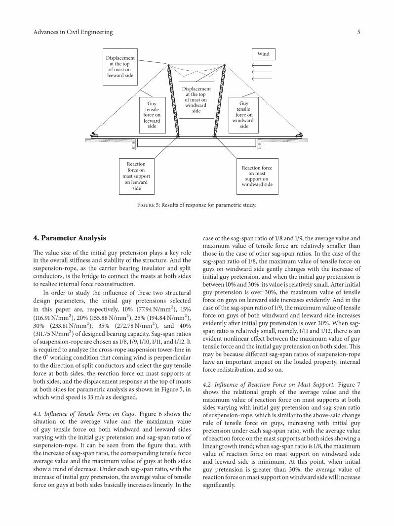

International Journal of
AerospaceEngineeringHindawi Publishing Corporationhttpwwwhindawicom Volume 2014
RoboticsJournal of
Hindawi Publishing Corporationhttpwwwhindawicom Volume 2014
Hindawi Publishing Corporationhttpwwwhindawicom Volume 2014
Active and Passive Electronic Components
Control Scienceand Engineering
Journal of
Hindawi Publishing Corporationhttpwwwhindawicom Volume 2014
International Journal of
RotatingMachinery
Hindawi Publishing Corporationhttpwwwhindawicom Volume 2014
Hindawi Publishing Corporation httpwwwhindawicom
Journal ofEngineeringVolume 2014
Submit your manuscripts athttpswwwhindawicom
VLSI Design
Hindawi Publishing Corporationhttpwwwhindawicom Volume 2014
Hindawi Publishing Corporationhttpwwwhindawicom Volume 2014
Shock and Vibration
Hindawi Publishing Corporationhttpwwwhindawicom Volume 2014
Civil EngineeringAdvances in
Acoustics and VibrationAdvances in
Hindawi Publishing Corporationhttpwwwhindawicom Volume 2014
Hindawi Publishing Corporationhttpwwwhindawicom Volume 2014
Electrical and Computer Engineering
Journal of
Advances inOptoElectronics
Hindawi Publishing Corporation httpwwwhindawicom
Volume 2014
The Scientific World JournalHindawi Publishing Corporation httpwwwhindawicom Volume 2014
SensorsJournal of
Hindawi Publishing Corporationhttpwwwhindawicom Volume 2014
Modelling amp Simulation in EngineeringHindawi Publishing Corporation httpwwwhindawicom Volume 2014
Hindawi Publishing Corporationhttpwwwhindawicom Volume 2014
Chemical EngineeringInternational Journal of Antennas and
Propagation
International Journal of
Hindawi Publishing Corporationhttpwwwhindawicom Volume 2014
Hindawi Publishing Corporationhttpwwwhindawicom Volume 2014
Navigation and Observation
International Journal of
Hindawi Publishing Corporationhttpwwwhindawicom Volume 2014
DistributedSensor Networks
International Journal of