Embed Size (px)
Citation preview
Parallel transmission for ultrahigh-fieldimagingFrancesco Padormoa, Arian Beqiria, Joseph V. Hajnala,b andShaihan J. Malika*
The development of MRI systems operating at or above 7 T has provided researchers with a new window into thehuman body, yielding improved imaging speed, resolution and signal-to-noise ratio. In order to fully realise the po-tential of ultrahigh-field MRI, a range of technical hurdles must be overcome. The non-uniformity of the transmitfield is one of such issues, as it leads to non-uniform images with spatially varying contrast. Parallel transmission(i.e. the use of multiple independent transmission channels) provides previously unavailable degrees of freedomthat allow full spatial and temporal control of the radiofrequency (RF) fields. This review discusses the many waysin which these degrees of freedom can be used, ranging from making more uniform transmit fields to the designof subject-tailored RF pulses for both uniform excitation and spatial selection, and also the control of the specificabsorption rate. © 2015 The Authors. NMR in Biomedicine published by John Wiley & Sons Ltd.
Keywords: ultrahigh-field MRI; parallel transmission; RF shimming; SAR; B1 mapping
INTRODUCTION
Recent years have seen increased popularity of human MRI sys-tems operating at ultrahigh magnetic field strength (B0 ≥ 7 T).However, operating at ultrahigh field (UHF) creates an additionalset of technical challenges which need to be solved before it canbe widely adopted. These problems originate from the interac-tion of the patient with the electromagnetic fields to which theyare exposed during the course of an MRI examination. Althoughthese interactions are present during examinations at lower fieldstrengths, they are more severe for UHF MRI and therefore resultin more significant image artefacts. The higher Larmor frequency(and consequently shorter electromagnetic radiation wave-length) results in wave interference effects becoming more pro-nounced (1–4). This manifests itself as inhomogeneity in boththe transmit and receive radiofrequency (RF) magnetic fields,B1+ and B1
–. Although more spatially variable receive fields resultin better parallel imaging performance (5,6), non-uniformitiesin the transmit field lead to spatially varying flip angles. Thiscan result in spatially varying contrast and, in the worst cases, re-gions in which no excitation can be achieved at all. Furthermore,the precise pattern of inhomogeneity is subject dependent (7). Amultitude of solutions have been proposed to address the prob-lems associated with B1
+ inhomogeneities, such as the use ofadiabatic RF pulses (8,9), dielectric pads (10–12) and dedicatedcoil designs (13,14). However, the most flexible approach is theuse of multiple transmission channels, known as parallel trans-mission (PTx), which is the subject of this review.The concept of multiple transmitters was proposed by Hoult
(15) and Ibrahim et al. (16) in 2000. The paper by Hoult investi-gated the fundamental limits of B1
+ homogeneity achievable bythe use of multiple coils to ‘shim’ the B1
+field in an analogous
manner to B0 shimming. The first consideration of the use ofmultiple channels in a realistic loaded coil was performed byIbrahim in a finite-difference time-domain numerical simulation
study, in which improved B1+field homogeneity was obtained
with a birdcage coil by driving each rung with a different phase.Interest in PTx increased greatly after the demonstration of
RF pulse acceleration by Katscher et al. (17) and Zhu (18). Itwas these papers that realised that PTx could provide full spa-tial and temporal control of the RF field, an idea which the
* Correspondence to: S. J. Malik, King’s College London, Division of Imaging Sci-ences and Biomedical Engineering, The Rayne Institute, 3rd Floor LambethWing, St Thomas’ Hospital, London, SE1 7EH, UK.E-mail: [email protected]
a F. Padormo, A. Beqiri, J. V. Hajnal, S. J. MalikDepartment of Biomedical Engineering, Division of Imaging Sciences and Bio-medical Engineering, King’s College London, King’s Health Partners, StThomas’ Hospital, London, UK
b J. V. HajnalCentre for the Developing Brain, Division of Imaging Sciences and BiomedicalEngineering, King’s College London, King’s Health Partners, St Thomas’ Hospi-tal, London, UK
This is an open access article under the terms of the Creative Com-mons Attribution License, which permits use, distribution and repro-duction in any medium, provided the original work is properly cited.
Abbreviations used: 2D/3D, two/three dimensional; CoV, coefficient ofvariation; DSC, direct signal control; EPG, extended phase graph; EPI, echoplanar imaging; FOV, field of view; FSE, fast spin echo; HW, hardware; LC,linear combination; LEx, local excitation; LLS, linear least squares; LTA, largetip angle; MaxMin, maximise the minimum; MLS, magnitude least squares;MP-RAGE, magnetisation-prepared rapid gradient echo; PatLoc, parallelimaging technique using local gradients; PNS, peripheral nerve stimulation;PSS, pseudo-steady state; PTx, parallel transmission; RF, radiofrequency; ROI,region of interest; SAR, specific absorption rate; SLR, Shinnar Le-Roux; SMS,simultaneous multi-slice; SNR, signal-to-noise ratio; SPINS, spiral non-selective; SR-EPG, spatially resolved extended phase graph; STA, small tipangle; TEM, transverse electromagnetic; TIAMO, time-interleaved acquisitionof modes; UHF, ultrahigh field; VERSE, variable rate selective excitation; VOP,virtual observation point.
Special issue review article
Received: 29 November 2014, Revised: 27 March 2015, Accepted: 29 March 2015, Published online in Wiley Online Library: 19 May 2015
(wileyonlinelibrary.com) DOI: 10.1002/nbm.3313
NMR Biomed. 2016; 29: 1145–1161 © 2015 The Authors. NMR in Biomedicine published by John Wiley & Sons Ltd.
1145
research community has latched on to with great enthusiasm.PTx has now transitioned from a purely research topic into clin-ical practice. Two channel transmitters are installed as standardin the latest clinical 3T systems from the major vendors, andmany new 7T scanners are now equipped with multiple trans-mit channels.
This review explains the fundamentals and latest develop-ments of PTx in its many different forms. This is achieved by clas-sification of the methods based on the different time frames atwhich differences between channels are exploited. We beginwith ’static PTx’, where the transmit settings are optimised onceat the beginning of the experiment and then remain fixed for therest of the scan. This is followed by ’dynamic PTx’, where differ-ences between channels are exploited at the shortest timeframes allowed by the system spectrometer. The intermediatearea of ‘multi-pulse PTx’ is then examined, followed by a discus-sion of further topics relevant to PTx.
FUNDAMENTAL CONCEPTS
PTx systems differ from standard scanners by their RF system ar-chitecture. The key component of a PTx system is the transmitcoil array, which must consist of several elements designed toproduce spatially distinct RF field patterns. Each is driven by itsown RF front end, consisting of multiple components. Althoughmany different specific RF front ends have been proposed in theliterature (19–23), for full PTx, all channels must be indepen-dently driven with full control over amplitude and phase modula-tion with microsecond temporal resolution. Each channel-specificwaveform requires a separate RF amplifier in order to deliverthe required power to each coil array element.
When driven with an RF pulse, the ith transmit element pro-duces RF magnetic and electric fields, denoted by B1,i(r, t) andEi(r, t), respectively. The NMR-active component of B1,i(r, t) is re-ferred to as B1,i
+ (r,t) = ½[B1,ix (r,t) + jB1,i
y (r,t)] (24,25), where the xand y directions are perpendicular to the static magnetic fieldand j = √–1.
The different forms of PTx can be understood by further exam-ining how they impact on the spatiotemporal nature of thetransmit field. According to the principle of superposition, thenet B1
+ produced inside the subject is the sum of the fields pro-duced by each element, as given by Equation [1a], where NT isthe number of transmit elements. However, the spatial and tem-poral components of B1,i
+ can be separated, as shown in Equation[1b]. Here, Si(r) is the spatial ‘footprint’ of a transmit element, of-ten referred to as the transmit sensitivity, and pi(t) is the RF pulseplayed through the ith transmitter. This equation describes‘dynamic PTx’, in which each coil element transmits its ownchannel-specific waveform. A further simplification is shown inEquation [1c], where the same RF pulse waveform, p(t), is trans-mitted on each channel, scaled by a channel-specific complexweight, wi. This equation describes ‘static PTx’. The final form ofPTx described by this paper is ‘multi-pulse PTx’, in which thechannel-specific weights or waveforms can change throughoutan MR sequence.
Bþ1 r; tð Þ ¼XNT
i¼1
Bþ1;i r; tð Þ (1a)
Bþ1 r; tð Þ ¼XNT
i¼1
pi tð ÞSi rð Þ (1b)
Bþ1 r; tð Þ ¼ p tð ÞXNT
i¼1
wiSi rð Þ (1c)
All PTx methods rely on some degree of prior knowledgeof Si(r) of each channel. This is achieved by ‘B1
+ mapping’,which is discussed later in this article. Full knowledge of Si(r) constitutes the measurement of its amplitude and itsphase relative to every other element at every location inspace. It should be noted that there are many ways to definethe units of S(r), wi and p(t) in a dimensionally consistentmanner; the specific selection by a user will probably dependon the specifics of the PTx system being used. Unless statedotherwise, the figures in this paper consider sensitivity mapsas dimensionless.The electric fields generated by each element also play an im-
portant role in PTx experiments, as it is the electric field which isresponsible for heating, with the specific absorption rate (SAR)used as a surrogate metric. Regulatory agencies place limits ontemperature increases and on local and whole-body SAR (26).SAR is a particular concern with PTx MRI because the total elec-tric field (which is the result of a linear superposition of fieldsfrom each transmit channel) becomes spatially and temporallyvariable, potentially making ‘hot spots’ in unexpected locations.Many of the methods described in this review attempt to explic-itly control SAR, often by using electric field information takenfrom numerical models. SAR is discussed in more detail later inthe review.Once the desired level of transmit and electric field informa-
tion has been collected or inferred, it can be used to designthe inputs to each of the transmit channels. Much PTx researchhas focused on the design of channel inputs with two separategoals in mind: (i) to overcome the effects of B1
+ inhomogeneity;and (ii) to achieve local excitation (LEx).B1+ inhomogeneity compensation can be achieved by all three
forms of PTx. In this review, we adopt the following terminologyfor clarity: B1
+ shimming refers to the use of static PTx to producea spatially uniform overall B1
+field; flip angle shimming refers to
the use of dynamic PTx to produce a spatially uniform flip angle;and signal shimming refers to the use of multi-pulse PTx to en-sure that each tissue type produces a spatially uniform signalin any measured image.However, it is important to note that, whatever the desired
goal (i.e. compensation for B1+ inhomogeneity, achievement of
LEx or something more elaborate), there are generic algorithmswith which the channel inputs can be determined. These differ-ent methods are described in the following sections.
STATIC PTX
The most basic form of parallel transmission is static PTx, whosegoal is to create the optimal conditions in a region of interest(ROI) by adjusting the complex weights (wi) with which the indi-vidual channels are driven, defined by Equation [1c].What constitutes ‘optimal’ depends on the specific application,
but the majority of static PTx demonstrations have focused on B1+
shimming. Initial methods specified the objective of uniform B1+
across the slice or volume being imaged (15,16,27–29). Alterna-tive pragmatic approaches were simultaneously being exploredexperimentally. The first physical implementation of B1
+ shimmingdemonstrated that the B1
+field could be optimised in specific
[1a]
[1b]
[1c]
F. PADORMO ET AL.
wileyonlinelibrary.com/journal/nbm © 2015 The Authors. NMR in Biomedicine published by John Wiley & Sons Ltd. NMR Biomed. 2016; 29: 1145–1161
1146

voxels using a two-port birdcage coil at 3 T (30). It was alsoshown that manual B1
+ shimming using operator interventionyielded more uniform images at UHF (31–33). However, it wassoon realised that demanding uniformity across the entire im-aged slice can be overly restrictive. One way of improving perfor-mance is to demand uniformity only over a smaller ROI – thisparticularly makes sense when imaging structures that aresmaller than the field of view (FOV) and was originally exploredin the context of 7T prostate imaging (34,35). As phase typicallyvaries slowly in space, simply aligning the average phase of eachchannel within the ROI often leads to a good solution (35), as allchannels are constructively interfering within the target region.This method has the advantage of not requiring the measure-ment of full B1
+ information. The second realisation to aid B1+
shimming was that the appearance of an image often criticallydepends on the magnitude of the transmit field, and that its spa-tial phase distribution is often unimportant. Hence, B1
+ shimmingalgorithms could relax their constraints, enabling solutions witha more homogeneous magnitude and inhomogeneous phaseto be found (29,36–38).Other static PTx methods have been designed with specific
applications in mind. For example, adiabatic pulses are only ef-fective when the B1
+ amplitude is above the adiabatic threshold.Therefore, methods have been designed to maximise theminimum (MaxMin) B1
+ without constraining uniformity, so thatthe adiabatic condition is met across the object (39,40). An-other static PTx method obtains the weights which producethe largest overall B1
+ amplitude per unit power deposited inthe patient (41).The use of static PTx for LEx has also been explored (42–45).
The utilised cost functions typically attempt to maximise the ra-tio of the B1
+field in a desired ROI to the B1
+field outside the ROI.
These methods have not yet been widely adopted, as theyrequire a large number of transmit channels to achieve the re-quired localisation in order to perform reduced FOV imaging;instead, LEx usually requires the design of full RF waveformsvia dynamic PTx, as discussed later.The majority of static PTx methods determine optimum
weights by solving a numerical optimisation problem, typicallyby iteratively minimising a cost function. Many different costfunctions have been proposed, with most consisting of errorterms to constrain the spatial B1
+ distribution (Φtarget), limit SAR(ΦSAR) and ensure the results are within hardware limits (ΦHW).Static PTx optimisation problems are posed in one of three
ways. The first is the regularised optimisation approach, in whichthe different penalised terms are added together, weighted bythe regularisation factors λ and μ, as given in Equation [2a].The cost function is typically solved for multiple values of λ andμ; these form a family of solutions with differing trade-offs be-tween cost terms, often visualised using ‘L-curves’ showing thesize of the component error terms. The solution that offers thebest compromise is selected. The second related approach isthe constrained optimisation framework (Equation [2b]). This en-ables the optimum of the B1
+ constraint term to be found forgiven SAR and hardware limits.
minimise Φtot ¼ Φtarget þ λΦSAR þ μΦHW (2a)
minimise Φtarget
subject to ΦSAR < SARmax
ΦHW < HWmax
(2b)
A selection of the different Φtarget used in different staticPTx methods is given in Table 1. The sensitivity matrix S isconstructed from the B1
+field information of all NT channels
in a user-defined ROI of NROI voxels. The information in theROI from the ith transmitter is reshaped into an NROI × 1 col-umn vector si, all of which are horizontally concatenated, sothat S ¼ s1; s2…; sNT½ �. The NT × 1 vector w contains the com-plex weights to each channel, and NROI × 1 vector b containsthe desired B1
+field distribution.
Details of the SAR constraints can be found in the SAR sectionlater in this review. For the sake of brevity, the additional hard-ware constraints are not described further, except to note thatthe most common additional constraint is for peak instanta-neous power, which is related to max{|w|}; detailed explanationsare given in refs. (46–48).
The third approach to obtain weights is to calculate them al-gebraically. These approaches do not require the use of optimi-sation algorithms as they can be found by simple arithmetic(35) or by performing matrix eigendecompositions (41).
Illustrative examples of several static PTx strategies are shownin Fig. 1. Figure 1A considers prostate imaging at 7 T using aneight-channel dipole array (49). Transmitting with the defaultweights of unit amplitude and zero phase (relative to an arbitraryreference) on each channel produces an overall B1
+field which is
high at the periphery and low in the ROI. Phase shimming resultsin a larger B1
+field in the ROI, but the greatest field focusing is
achieved using the maximum efficiency method. It should benoted that all solutions are scaled to have the same power(where power = wHw). Examining the weights themselves, thephase shimming algorithm is constrained to produce weightswith the same amplitude for all channels. The maximum effi-ciency approach can reweight channels appropriately to pro-duce a more efficient result. However, it should be noted thatphase shimming does not require full B1
+field information, which
can be difficult to acquire at 7 T.Figure 1B demonstrates two static PTx methods for a sagittal
brain slice using simulated data from a 12-channel transverseelectromagnetic (TEM) head coil. Again, it should be noted thatall solutions are scaled to have the same power. The defaultweights produce a field with a very large dynamic range. TheMaxMin algorithm produces a B1
+field which maximises the
lowest realised field in the slice, providing improved perfor-mance for adiabatic pulses. However, the overall non-uniformityremains, making these weights inappropriate for imaging usingnon-adiabatic pulses. Using the coefficient of variation (CoV)
Table 1. Example cost function terms Φtarget used to con-strain B1
+ in static parallel transmission (PTx) optimisationproblems
Field constraints Cost function term References
Linear leastsquares (LLS)
Sw� bk k22 (15,16,27–29)
Magnitude leastsquares (MLS)
Swj j � bk k22 (36–38)
Coefficient ofvariation (CoV)
std Swj jð Þmean Swj jð Þ
(29,34)
Maximise theminimum (MaxMin)
max(min(|Sw|)) (39,40)
[2a]
[2b]
PARALLEL TRANSMISSION FOR ULTRAHIGH-FIELD IMAGING
NMR Biomed. 2016; 29: 1145–1161 © 2015 The Authors. NMR in Biomedicine published by John Wiley & Sons Ltd. wileyonlinelibrary.com/journal/nbm
1147

metric produces a much more uniform B1+ appropriate for imag-
ing, but with a much lower mean amplitude as the solution isvery inefficient in terms of power.
The efficacy of static PTx has been widely demonstrated, par-ticularly for two-channel birdcage systems at 3 T, where B1
+
shimming has resulted in improved and more reliable imagingin many different clinical imaging scenarios (50–57), includingimaging near metal implants (58). Furthermore, it has beenshown that increasing the number of channels from two to eightimproves the performance of 3T in vivo body imaging (59), andfurther studies have shown further improvements with up to 32channels (60,61). B1
+ shimming has also been applied in vivo atUHF. Much work has focussed on the brain, withmultiple imagingdemonstrations at both 7 T (62–66) and 9.4 T (19,33,67–69), inaddition to spectroscopy (70–73). 7T body imaging has increasedin popularity, with B1
+ shimming being applied to cardiac (74–79),musculoskeletal (41,80–83), prostate (35,49,84–86), liver (87) andkidney (88–90) imaging.
DYNAMIC PTX
Static PTx is fundamentally limited to using the principle of su-perposition to achieve the goals of the pulse designer. Althoughit provides considerable control over B1
+, for many imaging sce-narios, the ability to achieve the desired B1
+ across large FOVs
at UHF is limited by the degrees of freedom provided by con-structively and destructively interfering a finite number of trans-mit sensitivities (29,60,61). However, additional flexibility can begained by recognizing that what is actually desired is a ‘flip an-gle’ distribution, which depends on the overall rotation of themagnetisation and not just the instantaneous B1
+. Dynamic PTxmodulates the B1
+field distribution over the shortest timescales,
with the aim of directly controlling the rotation of magnetization,and hence the overall flip angle, at multiple spatial locationssimultaneously. In this framework, the capabilities of PTx canextend far beyond that which is achievable with static PTx alone.The behaviour of magnetisation is described by the Bloch
equation. However, its non-linear behaviour in the transversemagnetisation when rotations are large is difficult to incorporateinto pulse design algorithms, and so the small tip angle (STA) ap-proximation is often made (91). This simplifies the pulse designproblem and introduces the concept of ‘transmit k-space’ (k(t),as defined by Equation [3]) to account for the effect of magneticfield gradients applied during the RF pulse.
k tð Þ ¼ �γ∫Tt G t′ð Þ dt′ (3)
Here T is the duration of the pulse and G(t) is the applied fieldgradient on all three axes. The key difference between transmitk-space and the more often used quantity for image encoding
Figure 1. Illustrative example of B1+ shimming. (A) Net transmit sensitivities produced by a 7T, eight-channel dipole array when transmitting with de-
fault drives (top left), phase shimming (centre left) and maximum efficiency (bottom left). The prostate is indicated by the red box. The average sen-sitivities in the regions of interest (ROIs) are given by SROI . The weights obtained for each method are given on the right. (B) Net transmitsensitivities produced by a 7T, 12-channel transverse electromagnetic (TEM) array with default drives (left), static parallel transmission (PTx) weightswhich maximise the minimum B1
+ (centre), and applying weights which minimise the coefficient of variation (right). The minimum sensitivity in eachslice is given by Smin. (Data courtesy of Dr Alessandro Sbrizzi, Dr Alexander Raaijmakers and Dr Hans Hoogduin, UMC Utrecht, the Netherlands).
[3]
F. PADORMO ET AL.
wileyonlinelibrary.com/journal/nbm © 2015 The Authors. NMR in Biomedicine published by John Wiley & Sons Ltd. NMR Biomed. 2016; 29: 1145–1161
1148
is the limits on the integral; in the transmit case, the integrationruns from ‘now into the future’, whereas, for image encoding, thelimits run from ‘the end of the excitation until now’. This can beunderstood by considering that, as the RF pulse is played out,new transverse magnetisation is being created, which is thensubject to all future applied gradients. The STA approximationis used for the majority of current PTx pulse design algorithms(17,18,92), with the spatial domain approach (92) widely adoptedas it is sufficiently flexible to incorporate B0 inhomogeneity, arbi-trary transmit k-space trajectories and spatial error weightings.As with static PTx, the pulses are obtained by minimising a costfunction, posed in the same manner as Equation [2a] or [2b]. Anexample using regularised optimisation with a linear least-squares (LLS) error term and total RF power constraint is givenby Equation [4]. Here, p is a vector containing the RF pulses ofall transmit channels, m is the desired transverse magnetisationvector and A is the system matrix, which contains all informationabout the excitation k-space trajectory and the transmit field pat-terns. The terms in Equation [4] are closely related to those incost functions used for static PTx. The vector p can be consid-ered to contain time-variable weights for the NP intervals in theRF pulse; Equation [4] reduces to the static PTx optimisation forthe case when NP = 1.
minimise Φtot ¼ Apk �mk22þλkpk22 [4]
This linear problem can be solved using a number ofmethods, such as conjugate gradients (93), and calculationscan be accelerated by taking advantage of non-uniform fastFourier transforms (94). As with static PTx, many alternative costfunctions have been proposed. If a spatially varyingmagnetisation phase is tolerable, the magnitude least-squares(MLS) method can again be applied (37,38). Optimisations that
account for SAR (18,46,47,95–98), hardware (46,48) or even ther-mal effects (99) can also be formulated in this framework, andthese can be solved using regularised or constrained optimisa-tions (46,47).
Given the above possibilities in formulating the cost function,the remaining issue becomes the choice of k-space trajectory.There are broadly two classes of trajectory – those used for flipangle shimming and those used for LEx. These are discussed inthe next two sections.
Dynamic PTx for flip angle shimming
PTx pulse design has been employed in cases in which B1+ shim-
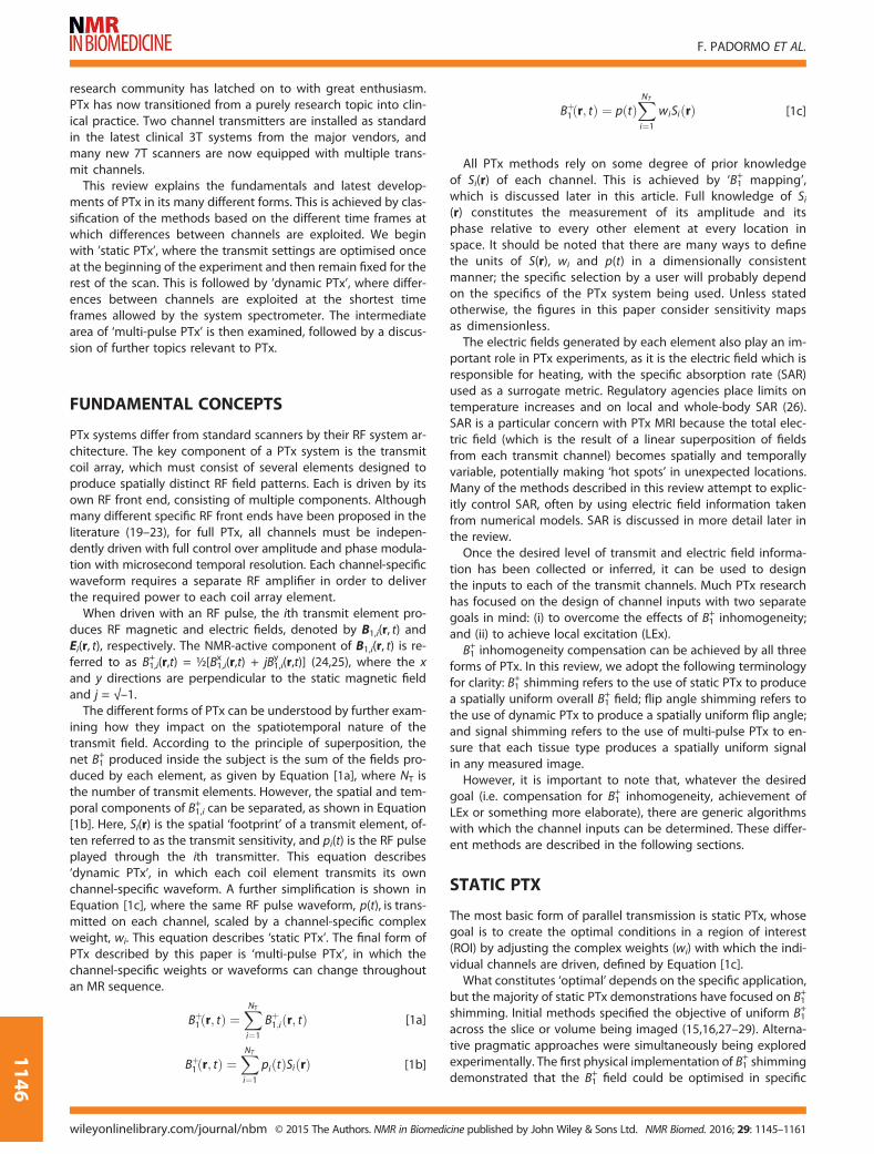
ming cannot achieve a sufficiently uniform flip angle across anROI. A variety of different k-space trajectories have been pro-posed, falling broadly into the two categories shown in Fig. 2;those that require slice or slab selection (top row), and thosewhich can be non-selective (bottom row). The selective trajecto-ries are formed of individual ‘spokes’ which each provide slice se-lectivity – a single spoke is equivalent to a single slice-selectivepulse. Additional in-plane spatial modulation is achieved byemploying multiple spokes that are offset in k-space; typically,these offsets correspond to low spatial frequency modulations,reflecting the spatial length scale of the B1
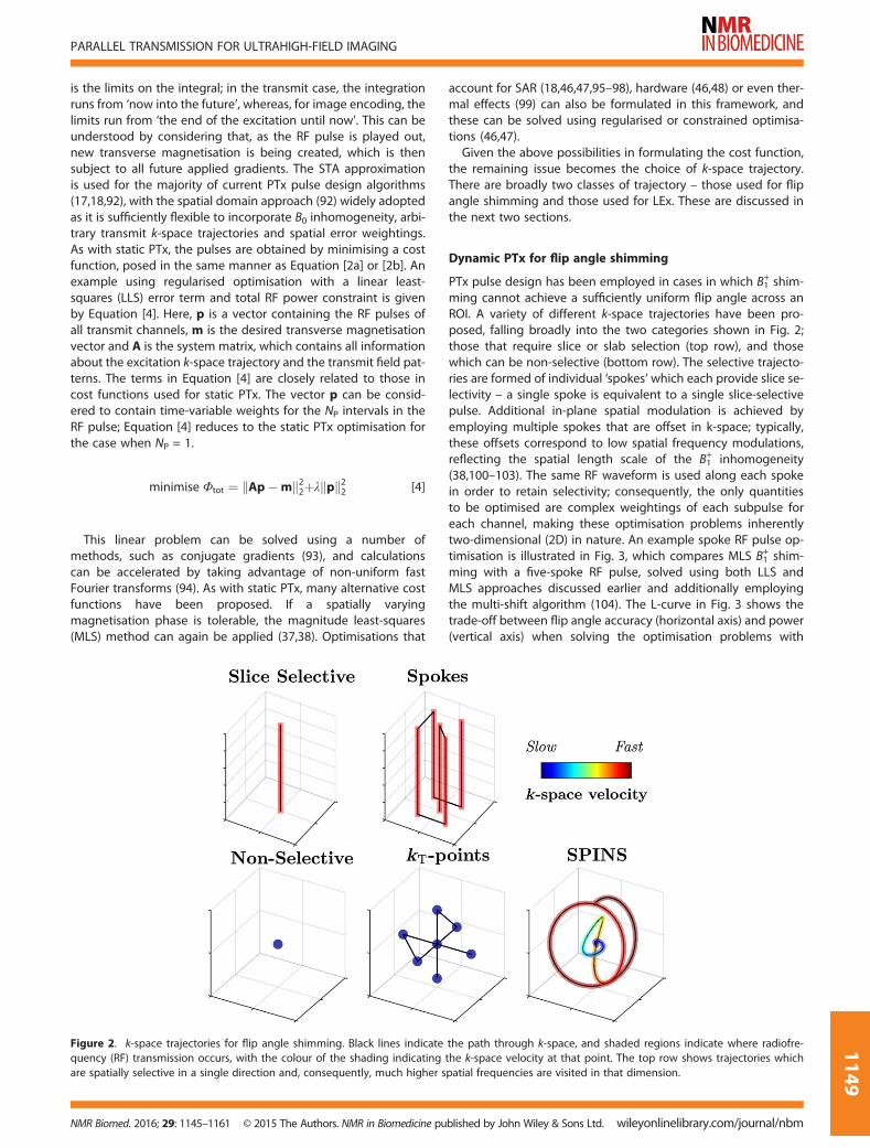
+ inhomogeneity(38,100–103). The same RF waveform is used along each spokein order to retain selectivity; consequently, the only quantitiesto be optimised are complex weightings of each subpulse foreach channel, making these optimisation problems inherentlytwo-dimensional (2D) in nature. An example spoke RF pulse op-timisation is illustrated in Fig. 3, which compares MLS B1
+ shim-ming with a five-spoke RF pulse, solved using both LLS andMLS approaches discussed earlier and additionally employingthe multi-shift algorithm (104). The L-curve in Fig. 3 shows thetrade-off between flip angle accuracy (horizontal axis) and power(vertical axis) when solving the optimisation problems with
Figure 2. k-space trajectories for flip angle shimming. Black lines indicate the path through k-space, and shaded regions indicate where radiofre-quency (RF) transmission occurs, with the colour of the shading indicating the k-space velocity at that point. The top row shows trajectories whichare spatially selective in a single direction and, consequently, much higher spatial frequencies are visited in that dimension.
PARALLEL TRANSMISSION FOR ULTRAHIGH-FIELD IMAGING
NMR Biomed. 2016; 29: 1145–1161 © 2015 The Authors. NMR in Biomedicine published by John Wiley & Sons Ltd. wileyonlinelibrary.com/journal/nbm
1149
different regularisation parameters. The MLS B1+ shimming result
is only able to produce a moderately uniform field. The LLSspokes method produces an excitation with a more uniformmagnitude, but is constrained to produce uniform phase. TheMLS spokes method produces the most uniform excitation byrelaxing the phase constraint.
If spatial selectivity is not necessary, simple hard pulses are of-ten employed (which correspond to a point at k = 0). Low-frequency k-space modulations can also be introduced in threedimensions; the kT-points method is a direct generalisation of2D spokes, with the trajectory ‘stopping’ at discrete locations ink-space (105). Alternatively, the ‘spiral non-selective’ (SPINS)method uses a continuously moving three-dimensional (3D)spiral trajectory to cover a low-frequency 3D k-space at variablevelocity (106).
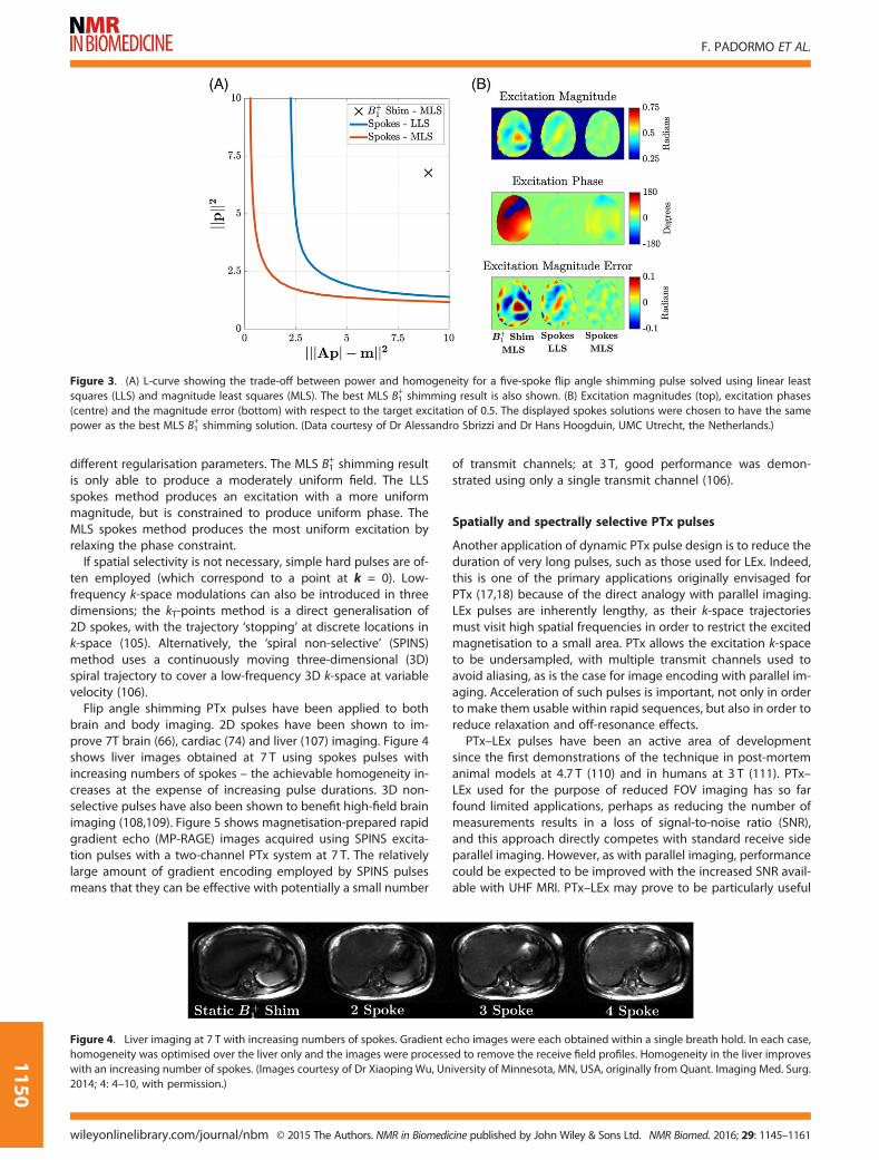
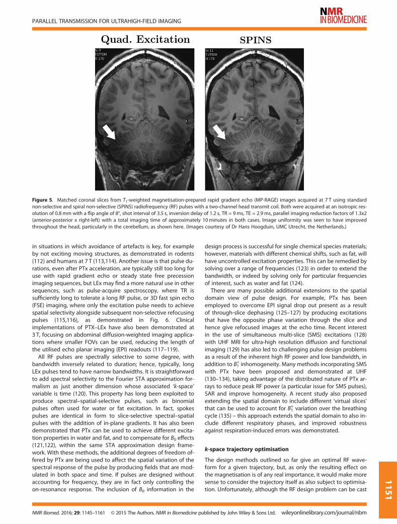
Flip angle shimming PTx pulses have been applied to bothbrain and body imaging. 2D spokes have been shown to im-prove 7T brain (66), cardiac (74) and liver (107) imaging. Figure 4shows liver images obtained at 7 T using spokes pulses withincreasing numbers of spokes – the achievable homogeneity in-creases at the expense of increasing pulse durations. 3D non-selective pulses have also been shown to benefit high-field brainimaging (108,109). Figure 5 shows magnetisation-prepared rapidgradient echo (MP-RAGE) images acquired using SPINS excita-tion pulses with a two-channel PTx system at 7 T. The relativelylarge amount of gradient encoding employed by SPINS pulsesmeans that they can be effective with potentially a small number
of transmit channels; at 3 T, good performance was demon-strated using only a single transmit channel (106).
Spatially and spectrally selective PTx pulses
Another application of dynamic PTx pulse design is to reduce theduration of very long pulses, such as those used for LEx. Indeed,this is one of the primary applications originally envisaged forPTx (17,18) because of the direct analogy with parallel imaging.LEx pulses are inherently lengthy, as their k-space trajectoriesmust visit high spatial frequencies in order to restrict the excitedmagnetisation to a small area. PTx allows the excitation k-spaceto be undersampled, with multiple transmit channels used toavoid aliasing, as is the case for image encoding with parallel im-aging. Acceleration of such pulses is important, not only in orderto make them usable within rapid sequences, but also in order toreduce relaxation and off-resonance effects.PTx–LEx pulses have been an active area of development
since the first demonstrations of the technique in post-mortemanimal models at 4.7 T (110) and in humans at 3 T (111). PTx–LEx used for the purpose of reduced FOV imaging has so farfound limited applications, perhaps as reducing the number ofmeasurements results in a loss of signal-to-noise ratio (SNR),and this approach directly competes with standard receive sideparallel imaging. However, as with parallel imaging, performancecould be expected to be improved with the increased SNR avail-able with UHF MRI. PTx–LEx may prove to be particularly useful
Figure 3. (A) L-curve showing the trade-off between power and homogeneity for a five-spoke flip angle shimming pulse solved using linear leastsquares (LLS) and magnitude least squares (MLS). The best MLS B1
+ shimming result is also shown. (B) Excitation magnitudes (top), excitation phases(centre) and the magnitude error (bottom) with respect to the target excitation of 0.5. The displayed spokes solutions were chosen to have the samepower as the best MLS B1
+ shimming solution. (Data courtesy of Dr Alessandro Sbrizzi and Dr Hans Hoogduin, UMC Utrecht, the Netherlands.)
Figure 4. Liver imaging at 7 T with increasing numbers of spokes. Gradient echo images were each obtained within a single breath hold. In each case,homogeneity was optimised over the liver only and the images were processed to remove the receive field profiles. Homogeneity in the liver improveswith an increasing number of spokes. (Images courtesy of Dr Xiaoping Wu, University of Minnesota, MN, USA, originally from Quant. Imaging Med. Surg.2014; 4: 4–10, with permission.)
F. PADORMO ET AL.
wileyonlinelibrary.com/journal/nbm © 2015 The Authors. NMR in Biomedicine published by John Wiley & Sons Ltd. NMR Biomed. 2016; 29: 1145–1161
1150
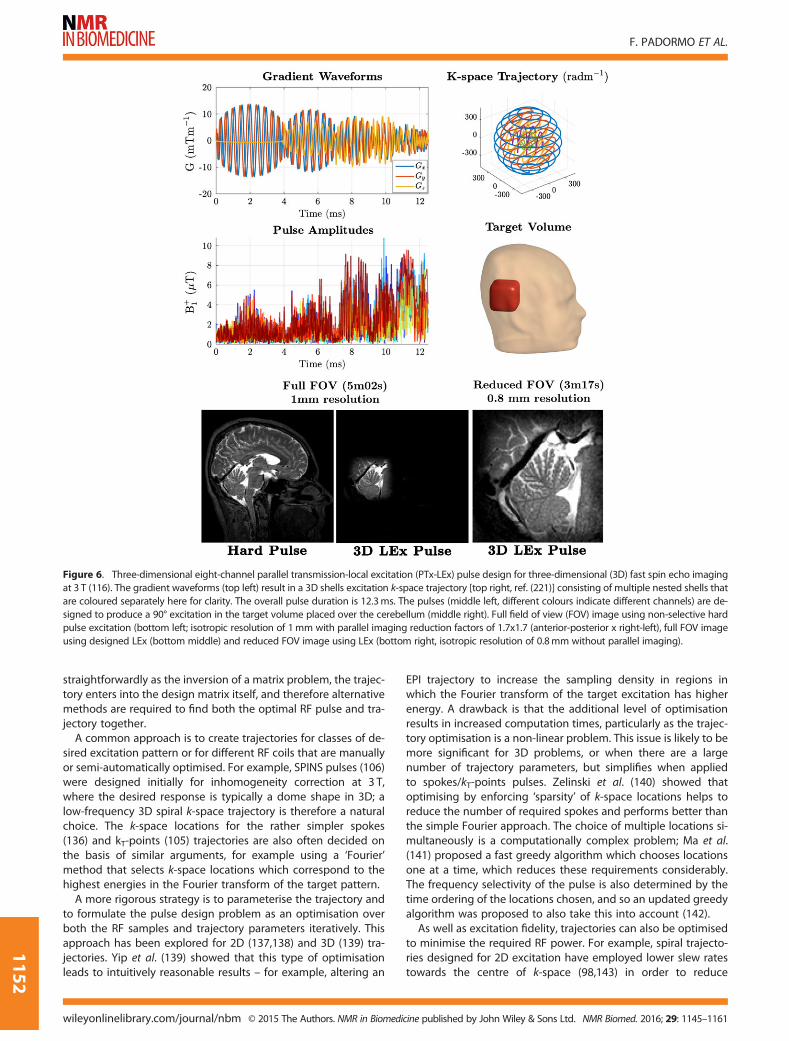
in situations in which avoidance of artefacts is key, for exampleby not exciting moving structures, as demonstrated in rodents(112) and humans at 7 T (113,114). Another issue is that pulse du-rations, even after PTx acceleration, are typically still too long foruse with rapid gradient echo or steady state free precessionimaging sequences, but LEx may find a more natural use in othersequences, such as pulse-acquire spectroscopy, where TR issufficiently long to tolerate a long RF pulse, or 3D fast spin echo(FSE) imaging, where only the excitation pulse needs to achievespatial selectivity alongside subsequent non-selective refocusingpulses (115,116), as demonstrated in Fig. 6. Clinicalimplementations of PTX–LEx have also been demonstrated at3 T, focusing on abdominal diffusion-weighted imaging applica-tions where smaller FOVs can be used, reducing the length ofthe utilised echo planar imaging (EPI) readouts (117–119).All RF pulses are spectrally selective to some degree, with
bandwidth inversely related to duration; hence, typically, longLEx pulses tend to have narrow bandwidths. It is straightforwardto add spectral selectivity to the Fourier STA approximation for-malism as just another dimension whose associated ‘k-space’variable is time (120). This property has long been exploited toproduce spectral–spatial-selective pulses, such as binomialpulses often used for water or fat excitation. In fact, spokespulses are identical in form to slice-selective spectral–spatialpulses with the addition of in-plane gradients. It has also beendemonstrated that PTx can be used to achieve different excita-tion properties in water and fat, and to compensate for B0 effects(121,122), within the same STA approximation design frame-work. With these methods, the additional degrees of freedom of-fered by PTx are being used to affect the spatial variation of thespectral response of the pulse by producing fields that are mod-ulated in both space and time. If pulses are designed withoutaccounting for frequency, they are in fact only controlling theon-resonance response. The inclusion of B0 information in the
design process is successful for single chemical species materials;however, materials with different chemical shifts, such as fat, willhave uncontrolled excitation properties. This can be remedied bysolving over a range of frequencies (123) in order to extend thebandwidth, or indeed by solving only for particular frequenciesof interest, such as water and fat (124).
There are many possible additional extensions to the spatialdomain view of pulse design. For example, PTx has beenemployed to overcome EPI signal drop out present as a resultof through-slice dephasing (125–127) by producing excitationsthat have the opposite phase variation through the slice andhence give refocused images at the echo time. Recent interestin the use of simultaneous multi-slice (SMS) excitations (128)with UHF MRI for ultra-high resolution diffusion and functionalimaging (129) has also led to challenging pulse design problemsas a result of the inherent high RF power and low bandwidth, inaddition to B1
+ inhomogeneity. Many methods incorporating SMSwith PTx have been proposed and demonstrated at UHF(130–134), taking advantage of the distributed nature of PTx ar-rays to reduce peak RF power (a particular issue for SMS pulses),SAR and improve homogeneity. A recent study also proposedextending the spatial domain to include different ‘virtual slices’that can be used to account for B1
+ variation over the breathingcycle (135) – this approach extends the spatial domain to also in-clude different respiratory phases, and improved robustnessagainst respiration-induced errors was demonstrated.
k-space trajectory optimisation
The design methods outlined so far give an optimal RF wave-form for a given trajectory, but, as only the resulting effect onthe magnetisation is of any real importance, it would make moresense to consider the trajectory itself as also subject to optimisa-tion. Unfortunately, although the RF design problem can be cast
Figure 5. Matched coronal slices from T1-weighted magnetisation-prepared rapid gradient echo (MP-RAGE) images acquired at 7 T using standardnon-selective and spiral non-selective (SPINS) radiofrequency (RF) pulses with a two-channel head transmit coil. Both were acquired at an isotropic res-olution of 0.8mm with a flip angle of 8°, shot interval of 3.5 s, inversion delay of 1.2 s, TR = 9ms, TE = 2.9ms, parallel imaging reduction factors of 1.3x2(anterior-posterior x right-left) with a total imaging time of approximately 10minutes in both cases. Image uniformity was seen to have improvedthroughout the head, particularly in the cerebellum, as shown here. (Images courtesy of Dr Hans Hoogduin, UMC Utrecht, the Netherlands.)
PARALLEL TRANSMISSION FOR ULTRAHIGH-FIELD IMAGING
NMR Biomed. 2016; 29: 1145–1161 © 2015 The Authors. NMR in Biomedicine published by John Wiley & Sons Ltd. wileyonlinelibrary.com/journal/nbm
1151
straightforwardly as the inversion of a matrix problem, the trajec-tory enters into the design matrix itself, and therefore alternativemethods are required to find both the optimal RF pulse and tra-jectory together.
A common approach is to create trajectories for classes of de-sired excitation pattern or for different RF coils that are manuallyor semi-automatically optimised. For example, SPINS pulses (106)were designed initially for inhomogeneity correction at 3 T,where the desired response is typically a dome shape in 3D; alow-frequency 3D spiral k-space trajectory is therefore a naturalchoice. The k-space locations for the rather simpler spokes(136) and kT-points (105) trajectories are also often decided onthe basis of similar arguments, for example using a ‘Fourier’method that selects k-space locations which correspond to thehighest energies in the Fourier transform of the target pattern.
A more rigorous strategy is to parameterise the trajectory andto formulate the pulse design problem as an optimisation overboth the RF samples and trajectory parameters iteratively. Thisapproach has been explored for 2D (137,138) and 3D (139) tra-jectories. Yip et al. (139) showed that this type of optimisationleads to intuitively reasonable results – for example, altering an
EPI trajectory to increase the sampling density in regions inwhich the Fourier transform of the target excitation has higherenergy. A drawback is that the additional level of optimisationresults in increased computation times, particularly as the trajec-tory optimisation is a non-linear problem. This issue is likely to bemore significant for 3D problems, or when there are a largenumber of trajectory parameters, but simplifies when appliedto spokes/kT-points pulses. Zelinski et al. (140) showed thatoptimising by enforcing ‘sparsity’ of k-space locations helps toreduce the number of required spokes and performs better thanthe simple Fourier approach. The choice of multiple locations si-multaneously is a computationally complex problem; Ma et al.(141) proposed a fast greedy algorithm which chooses locationsone at a time, which reduces these requirements considerably.The frequency selectivity of the pulse is also determined by thetime ordering of the locations chosen, and so an updated greedyalgorithm was proposed to also take this into account (142).As well as excitation fidelity, trajectories can also be optimised
to minimise the required RF power. For example, spiral trajecto-ries designed for 2D excitation have employed lower slew ratestowards the centre of k-space (98,143) in order to reduce
Figure 6. Three-dimensional eight-channel parallel transmission-local excitation (PTx-LEx) pulse design for three-dimensional (3D) fast spin echo imagingat 3 T (116). The gradient waveforms (top left) result in a 3D shells excitation k-space trajectory [top right, ref. (221)] consisting of multiple nested shells thatare coloured separately here for clarity. The overall pulse duration is 12.3ms. The pulses (middle left, different colours indicate different channels) are de-signed to produce a 90° excitation in the target volume placed over the cerebellum (middle right). Full field of view (FOV) image using non-selective hardpulse excitation (bottom left; isotropic resolution of 1mm with parallel imaging reduction factors of 1.7x1.7 (anterior-posterior x right-left), full FOV imageusing designed LEx (bottom middle) and reduced FOV image using LEx (bottom right, isotropic resolution of 0.8mm without parallel imaging).
F. PADORMO ET AL.
wileyonlinelibrary.com/journal/nbm © 2015 The Authors. NMR in Biomedicine published by John Wiley & Sons Ltd. NMR Biomed. 2016; 29: 1145–1161
1152

instantaneous RF power, similar to applying variable rate selec-tive excitation (VERSE) (144). An alternative solution is to numer-ically optimise a trajectory based on properties of the target(145,146). A more comprehensive approach for constrainingpeak instantaneous power was proposed by Lee et al. (147)who modified a time-optimal implementation of the VERSE algo-rithm (148) by transforming the constraint on peak RF power, sothat it could be included as a gradient constraint. An issue withVERSE is that time dilating RF pulses changes their off-resonanceproperties. Lee et al. (149) proposed an updated version of theirmethod which iteratively alters the RF design after time dilationto counter this issue.Of the methods discussed so far, some update k-space on a
per-subject basis (137,139,147,149), whereas others have a fixedtrajectory (and hence gradient waveform) for all subjects(106,143,145,146). Although the latter group is less flexible, thesemethods do avoid the performance of additional calculationswhilst the subject is in situ. Another advantage of this latter ap-proach is that gradient system imperfections can be calibratedin advance. PTx pulses with complex gradient waveforms are of-ten more sensitive than standard pulses to gradient system er-rors (150,151). In cases in which the waveforms do not changefrom subject to subject, these can be measured in advance withthe true trajectory used for pulse design (106,152); this is feasiblebecause the required corrections have been reported to remainstable over long periods of time (106). Methods that adapt trajec-tories for each subject may need to incorporate gradient imper-fections using models, for example by treating them as a lineartime-invariant system and employing an impulse responsefunction (116,153,154). Waveform measurement using MRI anditerative predistortion (155) of waveforms require gradientmeasurements that can be performed quickly with the subjectin situ; although image-based methods are available (for exam-ple, ref. (156)), this general approach is much more feasible ifgradient probe measurements are available (157).
Beyond the STA approximation
The STA approximation provides an elegant Fourier picturewhich is useful for discussion as well as for simplifying the designproblem. However, the linear k-space picture breaks down forlarge tip angles (LTAs) and, although some classes of k-space tra-jectory can produce satisfactory results (158), more sophisticateddesign methods are required. Non-PTx LTA pulse design can beperformed using the Shinnar Le-Roux (SLR) algorithm (159,160),which was recently extended to multidimensional k-space trajec-tories (161). However, other methods are required for LTA PTxdesign; many approaches have been proposed, and these typi-cally incorporate B1
+field information. A simple extension to
STA approximation pulse design is the ‘additive angle’ method(162), which uses STA approximation designed iteratively witha Bloch simulation, designing a new pulse at each stage to com-pensate for the errors of the previous one, and then summing allof these contributions at the end. This method can be improvedupon by performing a perturbation analysis of the Bloch equa-tions; the STA approximation is the first-order term, but higherorders can be addressed iteratively to improve the design(163). These methods usually require multiple Bloch equationsimulations to accurately model the magnetisation behaviour.The simplest case is that of ‘composite’ pulses, consisting oftrains of a few non-selective pulses; the solution to the Blochequations here can be boiled down to a set of simple rotations,
and these can be optimised numerically (164). More sophisti-cated pulses can be designed using optimal control methods,which solve dynamic optimisation problems with differentialequations as constraints. These have a long history of use withinMRI (for example, ref. (165)), and have been used recently for PTxRF pulse design (108,166–168), with much work carried out to re-duce computation times and to find globally rather than locallyoptimal solutions.
Finally, the trend of parallelising the subsystems of MRI scan-ners has recently been extended to gradients. The parallel imag-ing technique using local gradients (PatLoc) (169) and O-space(170) imaging offer the ability to image higher resolutions withlower peripheral nerve stimulation (PNS) by using non-bijectivegradients. PTx has been unified with these methods, but theFourier domain picture does not apply because of the non-linearity of the spatial gradients (171).
MULTI-PULSE PTX
So far, the methods discussed have either fixed the B1+field pat-
tern throughout an RF pulse or modulated it over very shorttimescales, during a single RF pulse. An intermediate timescalealso exists: modulation between pulses in one single sequence,referred to here as multi-pulse PTx. As discussed earlier, thereis typically a trade-off between achievable B1
+ homogeneity andRF power/SAR. One use for multi-pulse PTx is to apply thistrade-off flexibly within a sequence. Homann et al. (172) pro-posed switching static PTx weights mid-scan between highSAR, good B1
+ homogeneity settings when low-frequency k-spacedata are being acquired and low SAR, poor homogeneity set-tings when outer k-space data are being obtained. This mini-mises the impact of poor B1
+ homogeneity on image contrastwhich is dominated by the RF conditions when acquiring thecentre of k-space, whilst reducing the average SAR. Metzgeret al. (90) used a similar principle for inversion-prepared renal an-giography at 7 T; low SAR weights are used for adiabatic inver-sion pulses as these can tolerate some B1
+ inhomogeneity, buttypically have high associated SAR, whereas high B1
+ homogene-ity weights are used for excitation pulses whose homogeneitydirectly affects image quality, but which have a lower overall im-pact on the sequence SAR. A related method is time-interleavedacquisition of modes (TIAMO) (173,174), which can be used to re-move signal voids caused by regions of low or even zero B1
+
employing a parallel imaging reconstruction to create a compos-ite image of data acquired using interleaved static PTx driveswith different spatial sensitivity patterns that shift low B1
+ areasto different locations.
By their nature, MRI pulse sequences consist of many RFpulses, and the overall effect on the received signal dependson the interactions between these pulses and the spin system.All of the RF pulse design and shimming strategies discussedso far have treated each pulse in isolation; however, an alterna-tive is to take a more integrated approach. One example is todesign pairs of pulses together, which can be beneficial in situa-tions in which pulse properties need to be ‘matched’, as demon-strated for spin echo excitation and refocusing pulse pairs (175)and for flip-down/flip-up pairs (176).
In rapid imaging sequences, the magnetisation will reach asteady or pseudo-steady state (PSS) after many RF pulses; it hasbeen shown that dynamic modulation of the static PTx weightsduring FSE sequences (177) can lead to better image quality than
PARALLEL TRANSMISSION FOR ULTRAHIGH-FIELD IMAGING
NMR Biomed. 2016; 29: 1145–1161 © 2015 The Authors. NMR in Biomedicine published by John Wiley & Sons Ltd. wileyonlinelibrary.com/journal/nbm
1153

static B1+ shimming alone. This approach, referred to here as di-
rect signal control (DSC), is fundamentally different from thosediscussed so far. Although B1
+ shimming typically seeks to controlthe B1
+field pattern, and flip angle shimming controls the trans-
verse magnetisation at the end of an RF pulse, DSC may bethought of as ‘signal shimming’, where we seek to directly influ-ence the signals that will be received during an imaging se-quence consisting of multiple interacting RF pulses. One way ofachieving this is by performing a non-linear optimisation with re-spect to a signal model; for FSE sequences, this can be efficientlyconstructed from a spatially resolved extension to the well-known extended phase graph (EPG) formalism (178). Themethod has been applied to 3D FSE imaging at 3 T (179), and re-lated approaches which employ full PTx refocusing pulses havebeen demonstrated at 7 T (180–182), an example of which isillustrated in Fig. 7.
SAR
Increased SAR is intrinsically a problem for UHF MRI and is anarea in which PTx can have both positive and negative effects.As PTx results in spatiotemporal variations in electric (as well asmagnetic) RF fields, it can change the expected locations ofhot spots. If local SAR is not considered when performing PTxcalculations, a significant risk of heating can result. Global (i.e.whole body averaged) SAR can be estimated using measure-ments of forward and reflected power (183), but the estimationof local SAR typically requires a knowledge of electric fields.These cannot currently be measured reliably by MRI (although
it is an active research field (184–187)), and so this informationis typically provided by numerically solving Maxwell’s equationson a high-resolution grid (typically 1–5mm3) for digital bodymodels. Once obtained, the E-field data can be related to SARusing the Q-matrix framework (188), which represents, in a ma-trix, the contribution to SAR from each possible combination ofchannels. For example, the instantaneous local SAR is given byEquation [5], where σ(r) is the tissue conductivity, ρ(r) is the tis-sue density and Q(r) is the Q-matrix at location r. The globalSAR matrix Qglobal can be inferred by taking a weighted averageof the local Q matrices (189).
SARlocal rð Þ ¼ σ rð Þ2ρ rð Þw
HQ rð Þw [5]
All parts of the body exposed to the RF fields must be consid-ered when evaluating SAR, not just those in the imaging region.As the location of maximum local SAR can occur anywhere and isnot known a priori, Equation [5] must be evaluated for every lo-cation in space to ensure that regulatory limits are met. This istime consuming because of the sheer number of matrices, oftenin the range of 106–108. This process can be significantly acceler-ated by taking advantage of the positive semi-definite nature ofthe Q-matrices to form a smaller subset (known as ‘virtual obser-vation points’) of Q-matrices, QVOP, whose local SAR valuesdominate the calculation (190,191). Compression factors ofthe order of 5000 have been demonstrated for human modelswith eight transmit channels (190) with the guarantee of no
Figure 7. T2-weighted three-dimensional fast spin echo (FSE) imaging at 7 T using dynamically modulated kT-points radiofrequency (RF) pulses for ex-citation and refocusing. The diagram (bottom) depicts the kT-points RF pulses used, consisting of multiple hard pulses. The amplitudes and phases ofthese hard pulses are optimised so that, during each shot of the FSE sequence, the magnetization is brought to a pseudo-steady state (PSS) with de-sired echo amplitude by the first P1 pulse (here P1 = 10), and then subsequently maintained in this state, despite the presence of strong B1
+ non-uni-formity. The spatially resolved extended phase graph (SR-EPG) framework is used to predict the echo amplitudes for all locations in space and at eachTE, and these are optimized to be uniform (182). Dynamic modulation allows more uniform signals to be obtained, recovering reduced signals that areapparent in the temporal lobes (see increased signal apparent on the ratio image). (Images courtesy of Dr Florent Eggenschwiler, CIBM, Lausanne,Switzerland.)
F. PADORMO ET AL.
wileyonlinelibrary.com/journal/nbm © 2015 The Authors. NMR in Biomedicine published by John Wiley & Sons Ltd. NMR Biomed. 2016; 29: 1145–1161
1154

underestimation of max{SARlocal} and a prescribed limit for over-estimation, in this case 5%.Much work has gone into understanding the exact properties
of the required digital body models (for example, ref. (192)).Many strategies have been proposed, including the productionof patient-specific whole-body models based on in situ scans ofa given subject (193), the creation of patient-specific models byimage registration (194) or the use of generic models with a suit-ably chosen conservative safety factor (195). Although the major-ity of proposed methods rely on some form of SAR model, othersare also exploring the possibility of direct in vivo measurementby post-processing B1
+ maps, with results demonstrated at 3 T(196) and 7 T (185). Clearly, direct measurement of SAR wouldbe ideal; however, these methods could only be practically usedif the necessary data could be acquired quickly so as not to com-promise the examination itself – this is made more challengingby the fact that areas of elevated SAR can occur far from the sliceor volume that is being considered for imaging, and so SAR mea-surements will necessarily require large fields of view for manycoil designs. Direct measurements of temperature increases arealso being explored as a way of determining safe scanning usingMR thermometry (187,197).Once SAR information has been obtained, it can be used to
limit SAR within pulse sequences (90,172,173). For PTx pulse de-signs, this is achieved by incorporating SAR penalisation termsinto the cost functions minimised to calculate the pulse wave-forms (e.g. Equations [2] and [4]). Table 2 describes the SARterms commonly used in static PTx optimisation problems. All in-volve a quadratic form of the weights and Q-matrices. Theseterms can be easily generalised for dynamic PTx pulse calcula-tions to limit local SAR (46,47). This type of constraint is useful,given that it has been shown that maximum local SAR, in partic-ular, can vary strongly when pulse design parameters arechanged (198). It has also been proposed that pulse design canbe used to directly constrain temperature rather than SAR, bycombining SAR models with biophysical thermal models utilisingthe Pennes bioheat equation (99).Rather than viewing SAR as a constraint, the reduction of SAR
can be seen as the major target of any optimisation – Zhu (18)discussed this possibility in his early paper on PTx, and it hasbeen shown that simultaneous reductions in local SAR and B1
+
inhomogeneity can be achieved by performing B1+ shimming
within localised ROIs for prostate imaging at 7 T (34) and for car-diac imaging at 3 T (199). A further application of PTx has beenthe control and reduction of SAR in the presence of implanted
or interventional devices (200–203). These methods use spatialcontrol of RF electric fields, made possible by PTx, in order tominimise heating effects using simulated electric fields or in situmeasurements of electrical coupling for optimisation. This is apromising application for PTx that has so far been of particularinterest at lower field strengths.
Finally, it should also be noted that electric fields and SAR de-pend on the utilised RF coil. It has been shown that certain trans-mit arrays can be driven using a basis of circularly polarisedmodes (204), some of which produce very little B1
+ yet significantelectric fields. Although they produce very little B1
+, these ‘darkmodes’ can be used to cancel electric fields produced by themore B1
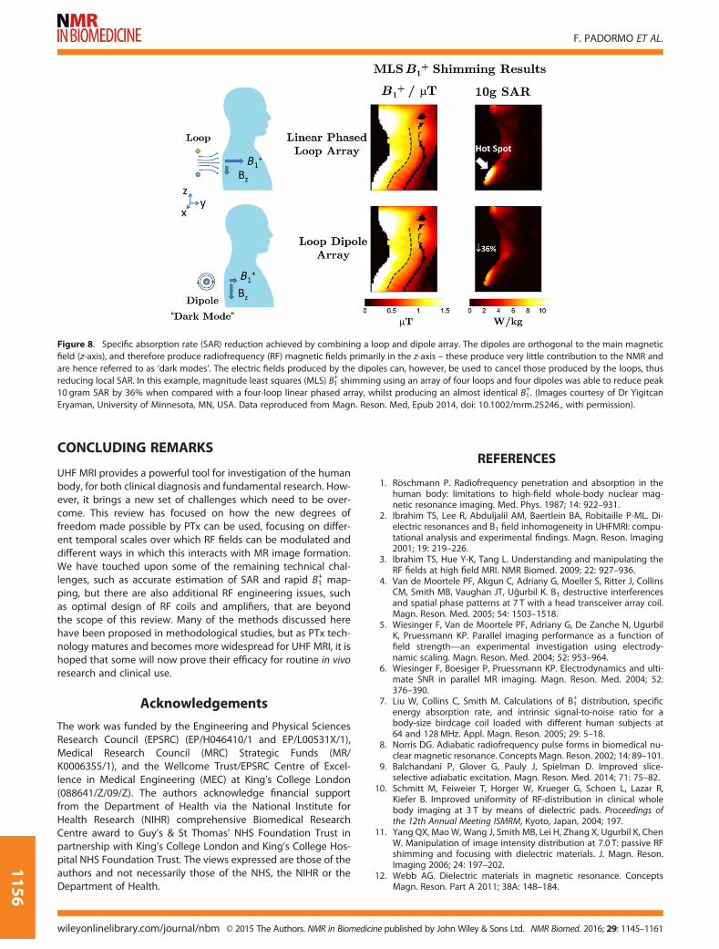
+ efficient modes to reduce SAR hotspots (205). Takingthis concept further, it is possible to design coil arrays with somededicated ‘dark’ elements that primarily produce electric fields.An example of such a system is illustrated in Fig. 8 from ref.(206), where dipole antennas are employed in conjunction withloops. Although this design is unconventional, each element inthis array is driven independently, and it may be used in exactlythe same way as any other PTx array using any of the optimiza-tion methods outlined previously. It has been demonstrated thatpotentially large reductions in local SAR (206) can be achieved.Although these approaches are still in their infancy, previous the-oretical studies into optimal current distributions suggest thatthere are significant benefits yet to be obtained (61,207).
B1+ MAPPING
PTx methods inherently require some knowledge of the transmitfield produced by each element of the transmit array. This informa-tion is typically acquired in situ, and many different strategies havebeen proposed. Themost basic approach involves the utilisation ofa sequence which measures the magnitude of the transmit field(for example, see refs. (208–211)), and repeating this for each trans-mitter. The relative phase of each transmitter is either obtainedfrom the phase of the images acquired or, in some cases, from adedicated acquisition (212). This approach is typically lengthy, asthe majority of B1
+ mapping methods (apart from recently pro-posed exceptions (211–213)) are slow and, unlike receive fieldmapping, transmit channels must be mapped sequentially. An-other approach is to acquire only a single magnitude transmit fieldmap of all coils transmitting in a default configuration, supple-mented by a series of low-flip-angle spoiled gradient echo im-ages (214,215) (whose signal is proportional to the B1
+field) from
which relative transmitter information can be obtained. This tech-nique is fast, as the data acquisition is very efficient with low SAR.
UHF B1+ mapping is more challenging than at lower field
strengths, primarily because of the increased dynamic range ofthe transmit field; typically very large B1
+ is produced adjacentto coil elements, with very low and often zero amplitudes pro-duced further away within the FOV. All B1
+ mapping methodshave a limited range of flip angles over which they can acquireaccurate measurements (216). In order to combat this, the useof linear combinations (LCs), constructed so as to reduce the dy-namic range, has been proposed (217,218). The choice of LC usu-ally requires a trade-off between reducing the dynamic rangeand the ability to invert the measurements (219). Recent workat 9.4 T has suggested that Fourier encoding is a good choiceusing an eight-channel head coil (220), but work at 3 T hasshown that the best choice of LC is coil array and load specific(219), and a suitable LC cannot always be found.
Table 2. Example cost function terms ΦSAR used to con-strain the specific absorption rate (SAR) in static paralleltransmission (PTx) optimisation problems
Energy constraints Cost function term References
Total RF power(I, identity matrix)
wHIw (92)
Global SAR wHQglobalw (18)
Local SAR (index iruns over all spatiallocations)
wHQ(ri)w ∀ i (46)
VOP SAR (index iruns over all VOPs)
wHQVOPi w ∀ i (191,192)
PARALLEL TRANSMISSION FOR ULTRAHIGH-FIELD IMAGING
NMR Biomed. 2016; 29: 1145–1161 © 2015 The Authors. NMR in Biomedicine published by John Wiley & Sons Ltd. wileyonlinelibrary.com/journal/nbm
1155
CONCLUDING REMARKS
UHF MRI provides a powerful tool for investigation of the humanbody, for both clinical diagnosis and fundamental research. How-ever, it brings a new set of challenges which need to be over-come. This review has focused on how the new degrees offreedom made possible by PTx can be used, focusing on differ-ent temporal scales over which RF fields can be modulated anddifferent ways in which this interacts with MR image formation.We have touched upon some of the remaining technical chal-lenges, such as accurate estimation of SAR and rapid B1
+ map-ping, but there are also additional RF engineering issues, suchas optimal design of RF coils and amplifiers, that are beyondthe scope of this review. Many of the methods discussed herehave been proposed in methodological studies, but as PTx tech-nology matures and becomes more widespread for UHF MRI, it ishoped that some will now prove their efficacy for routine in vivoresearch and clinical use.
Acknowledgements
The work was funded by the Engineering and Physical SciencesResearch Council (EPSRC) (EP/H046410/1 and EP/L00531X/1),Medical Research Council (MRC) Strategic Funds (MR/K0006355/1), and the Wellcome Trust/EPSRC Centre of Excel-lence in Medical Engineering (MEC) at King’s College London(088641/Z/09/Z). The authors acknowledge financial supportfrom the Department of Health via the National Institute forHealth Research (NIHR) comprehensive Biomedical ResearchCentre award to Guy’s & St Thomas’ NHS Foundation Trust inpartnership with King’s College London and King’s College Hos-pital NHS Foundation Trust. The views expressed are those of theauthors and not necessarily those of the NHS, the NIHR or theDepartment of Health.
REFERENCES
1. Röschmann P. Radiofrequency penetration and absorption in thehuman body: limitations to high-field whole-body nuclear mag-netic resonance imaging. Med. Phys. 1987; 14: 922–931.
2. Ibrahim TS, Lee R, Abduljalil AM, Baertlein BA, Robitaille P-ML. Di-electric resonances and B1 field inhomogeneity in UHFMRI: compu-tational analysis and experimental findings. Magn. Reson. Imaging2001; 19: 219–226.
3. Ibrahim TS, Hue Y-K, Tang L. Understanding and manipulating theRF fields at high field MRI. NMR Biomed. 2009; 22: 927–936.
4. Van de Moortele PF, Akgun C, Adriany G, Moeller S, Ritter J, CollinsCM, Smith MB, Vaughan JT, Uğurbil K. B1 destructive interferencesand spatial phase patterns at 7 T with a head transceiver array coil.Magn. Reson. Med. 2005; 54: 1503–1518.
5. Wiesinger F, Van de Moortele PF, Adriany G, De Zanche N, UgurbilK, Pruessmann KP. Parallel imaging performance as a function offield strength—an experimental investigation using electrody-namic scaling. Magn. Reson. Med. 2004; 52: 953–964.
6. Wiesinger F, Boesiger P, Pruessmann KP. Electrodynamics and ulti-mate SNR in parallel MR imaging. Magn. Reson. Med. 2004; 52:376–390.
7. Liu W, Collins C, Smith M. Calculations of B1+ distribution, specific
energy absorption rate, and intrinsic signal-to-noise ratio for abody-size birdcage coil loaded with different human subjects at64 and 128MHz. Appl. Magn. Reson. 2005; 29: 5–18.
8. Norris DG. Adiabatic radiofrequency pulse forms in biomedical nu-clear magnetic resonance. Concepts Magn. Reson. 2002; 14: 89–101.
9. Balchandani P, Glover G, Pauly J, Spielman D. Improved slice-selective adiabatic excitation. Magn. Reson. Med. 2014; 71: 75–82.
10. Schmitt M, Feiweier T, Horger W, Krueger G, Schoen L, Lazar R,Kiefer B. Improved uniformity of RF-distribution in clinical wholebody imaging at 3 T by means of dielectric pads. Proceedings ofthe 12th Annual Meeting ISMRM, Kyoto, Japan, 2004; 197.
11. Yang QX, Mao W, Wang J, Smith MB, Lei H, Zhang X, Ugurbil K, ChenW. Manipulation of image intensity distribution at 7.0 T: passive RFshimming and focusing with dielectric materials. J. Magn. Reson.Imaging 2006; 24: 197–202.
12. Webb AG. Dielectric materials in magnetic resonance. ConceptsMagn. Reson. Part A 2011; 38A: 148–184.
Figure 8. Specific absorption rate (SAR) reduction achieved by combining a loop and dipole array. The dipoles are orthogonal to the main magneticfield (z-axis), and therefore produce radiofrequency (RF) magnetic fields primarily in the z-axis – these produce very little contribution to the NMR andare hence referred to as ‘dark modes’. The electric fields produced by the dipoles can, however, be used to cancel those produced by the loops, thusreducing local SAR. In this example, magnitude least squares (MLS) B1
+ shimming using an array of four loops and four dipoles was able to reduce peak10 gram SAR by 36% when compared with a four-loop linear phased array, whilst producing an almost identical B1
+. (Images courtesy of Dr YigitcanEryaman, University of Minnesota, MN, USA. Data reproduced from Magn. Reson. Med, Epub 2014, doi: 10.1002/mrm.25246., with permission).
F. PADORMO ET AL.
wileyonlinelibrary.com/journal/nbm © 2015 The Authors. NMR in Biomedicine published by John Wiley & Sons Ltd. NMR Biomed. 2016; 29: 1145–1161
1156

13. Alsop DC, Connick TJ, Mizsei G. A spiral volume coil for improved RFfield homogeneity at high static magnetic field strength. Magn.Reson. Med. 1998; 40: 49–54.
14. Vaughan JT, Hetherington HP, Otu JO, Pan JW, Pohost GM. High fre-quency volume coils for clinical NMR imaging and spectroscopy.Magn. Reson. Med. 1994; 32: 206–218.
15. Hoult DI. Sensitivity and power deposition in a high-field imagingexperiment. J. Magn. Reson. Imaging 2000; 12: 46–67.
16. Ibrahim TS, Lee R, Baertlein BA, Kangarlu A, Robitaille P-ML. Applica-tion of finite difference time domain method for the design of bird-cage RF head coils using multi-port excitations. Magn. Reson.Imaging 2000; 18: 733–742.
17. Katscher U, Börnert P, Leussler C, Van den Brink JS. Transmit SENSE.Magn. Reson. Med. 2003; 49: 144–150.
18. Zhu Y. Parallel excitation with an array of transmit coils. Magn.Reson. Med. 2004; 51: 775–784.
19. Shajan G, Hoffmann J, Budde J, Adriany G, Ugurbil K, Pohmann R.Design and evaluation of an RF front-end for 9.4 T human MRI.Magn. Reson. Med. 2011; 66: 594–602.
20. Hoult DI, Kolansky G, Kripiakevich D, King SB. The NMR multi-transmit phased array: a Cartesian feedback approach. J. Magn.Reson. 2004; 171: 64–70.
21. Stang PP, Conolly SM, Santos JM, Pauly JM, Scott GC. Medusa: ascalable MR console using USB. IEEE Trans. Med. Imaging 2012;31: 370–379.
22. Gudino N, Heilman JA, Riffe MJ, Heid O, Vester M, Griswold MA. On-coil multiple channel transmit system based on class-D amplifica-tion and pre-amplification with current amplitude feedback. Magn.Reson. Med. 2013; 70: 276–289.
23. Chu X, Yang X, Liu Y, Sabate J, Zhu Y. Ultra-low output impedanceRF power amplifier for parallel excitation. Magn. Reson. Med.2009; 61: 952–961.
24. Hoult DI. The principle of reciprocity in signal strength calcula-tions—a mathematical guide. Concepts Magn. Reson. 2000; 12:173–187.
25. Collins CM, Wang Z. Calculation of radiofrequency electromagneticfields and their effects in MRI of human subjects. Magn. Reson.Med. 2011; 65: 1470–1482.
26. International Electrotechnical Commission (IEC). Medical electricalequipment - Part 2-33: Particular requirements for the basic safetyand essential performance of magnetic resonance equipment formedical diagnosis (IEC-60601-2-33). IEC: Geneva; 2010.
27. Ibrahim TS, Lee R, Baertlein BA, Abduljalil AM, Zhu H, RobitailleP-ML. Effect of RF coil excitation on field inhomogeneity at ultrahigh fields: a field optimized TEM resonator. Magn. Reson. Imaging2001; 19: 1339–1347.
28. Wang ZJ, Chu Z. Achieving plane-wise uniform B1 amplitude in a 3Dvolume for high-field MRI: a computer simulation study. J. Magn.Reson. Imaging 2006; 24: 218–225.
29. Mao W, Smith MB, Collins CM. Exploring the limits of RF shimmingfor high-field MRI of the human head. Magn. Reson. Med. 2006; 56:918–922.
30. Seifert F, Rinneberg H. Adaptive coil control: SNR optimization of aTR volume coil for single voxel MRS at 3 T. Proceedings of the 10thAnnual Meeting ISMRM, Honolulu, HI, USA, 2002; 162.
31. Vaughan JT, Adriany G, Snyder CJ, Tian J, Thiel T, Bolinger L, Liu H,DelaBarre L, Ugurbil K. Efficient high-frequency body coil for high-field MRI. Magn. Reson. Med. 2004; 52: 851–859.
32. Adriany G, Van de Moortele PF, Wiesinger F, Moeller S, Strupp JP,Andersen P, Snyder C, Zhang X, Chen W, Pruessmann KP, BoesigerP, Vaughan T, Uğurbil K. Transmit and receive transmission linearrays for 7 Tesla parallel imaging. Magn. Reson. Med. 2005; 53:434–445.
33. Vaughan T, DelaBarre L, Snyder C, Tian J, Akgun C, Shrivastava D,Liu W, Olson C, Adriany G, Strupp J, Andersen P, Gopinath A, Vande Moortele PF, Garwood M, Ugurbil K. 9.4 T human MRI: prelimi-nary results. Magn. Reson. Med. 2006; 56: 1274–1282.
34. Van den Bergen B, Van den Berg CAT, Bartels LW, Lagendijk JJW. 7 Tbody MRI: B1 shimming with simultaneous SAR reduction. Phys.Med. Biol. 2007; 52: 5429–5441.
35. Metzger GJ, Snyder C, Akgun C, Vaughan T, Ugurbil K,Van de Moortele PF. Local B1
+ shimming for prostate imagingwith transceiver arrays at 7 T based on subject-dependenttransmit phase measurements. Magn. Reson. Med. 2008; 59:396–409.
36. Katscher U, Vernickel P, Graesslin I, Börnert P. RF shimming using amulti-element transmit system in phantom and in vivo studies.Proceedings of the Joint Annual Meeting ISMRM-ESMRMB, Berlin,Germany, 2007; 1693.
37. Kerr AB, Zhu Y, Pauly JM. Phase constraint relaxation in parallel ex-citation pulse design. Proceedings of the Joint Annual MeetingISMRM-ESMRMB, Berlin, Germany, 2007; 1694.
38. Setsompop K, Wald LL, Alagappan V, Gagoski BA, Adalsteinsson E.Magnitude least squares optimization for parallel radio frequencyexcitation design demonstrated at 7 Tesla with eight channels.Magn. Reson. Med. 2008; 59: 908–915.
39. Setsompop K,Wald LL, Adalsteinsson E. Reduced-voltage RF shimmingfor adiabatic pulse design in parallel transmission. Proceedings of theJoint Annual Meeting ISMRM-ESMRMB, Berlin, Germany, 2007; 1687.
40. Balchandani P, Khalighi MM, Hsieh SS, Setsompop K, Pauly J,Spielman D. Adiabatic B1 shimming algorithm for multiple channeltransmit at 7 T. Proceedings of the 19th Annual Meeting ISMRM,Montreal, QC, Canada, 2011; 2907.
41. Deniz CM, Brown R, Lattanzi R, Alon L, Sodickson DK, Zhu Y. Maxi-mum efficiency radiofrequency shimming: theory and initial appli-cation for hip imaging at 7 tesla. Magn. Reson. Med. 2013; 69:1379–1388.
42. Ibrahim TS. Ultrahigh-field MRI whole-slice and localized RF field ex-citations using the same RF transmit array. IEEE Trans. Med. Imaging2006; 25: 1341–1347.
43. Abraham R, Ibrahim TS. Proposed radiofrequency phased-array ex-citation scheme for homogenous and localized 7-Tesla whole-bodyimaging based on full-wave numerical simulations. Magn. Reson.Med. 2007; 57: 235–242.
44. Olson C, Yoo H, Delabarre L, Vaughan JT, Gopinath A. RF B1 field lo-calization through convex optimization. Microw. Opt. Technol. Lett.2012; 54: 31–37.
45. Yoo H, Gopinath A, Vaughan JT. A method to localize RF field inhigh-field magnetic resonance imaging systems. IEEE Trans.Biomed. Eng. 2012; 59: 3365–3371.
46. Brunner DO, Pruessmann KP. Optimal design of multiple-channelRF pulses under strict power and SAR constraints. Magn. Reson.Med. 2010; 63: 1280–1291.
47. Guérin B, Gebhardt M, Cauley S, Adalsteinsson E, Wald LL. Localspecific absorption rate (SAR), global SAR, transmitter power, andexcitation accuracy trade-offs in low flip-angle parallel transmitpulse design. Magn. Reson. Med. 2014; 71: 1446–1457.
48. Grissom WA, Kerr AB, Stang P, Scott GC, Pauly JM. Minimumenvelope roughness pulse design for reduced amplifier distortionin parallel excitation. Magn. Reson. Med. 2010; 64: 1432–1439.
49. Raaijmakers AJE, Ipek O, Klomp DWJ, Possanzini C, Harvey PR,Lagendijk JJW, Van den Berg CAT. Design of a radiative surface coilarray element at 7 T: the single-side adapted dipole antenna. Magn.Reson. Med. 2011; 66: 1488–1497.
50. Willinek WA, Gieseke J, Kukuk GM, Nelles M, König R, Morakkabati-Spitz N, Träber F, Thomas D, Kuhl CK, Schild HH. Dual-source parallelradiofrequency excitation body MR imaging compared with stan-dard MR imaging at 3.0 T: initial clinical experience. Radiology2010; 256: 966–975.
51. Nelles M, König RS, Gieseke J, Guerand-van Battum MM, Kukuk GM,Schild HH, Willinek WA. Dual-source parallel RF transmission forclinical MR imaging of the spine at 3.0 T: intraindividual comparisonwith conventional single-source transmission. Radiology 2010; 257:743–753.
52. Kukuk GM, Gieseke J, Weber S, Hadizadeh DR, Nelles M, Träber F,Schild HH, Willinek WA. Focal liver lesions at 3.0 T: lesion detectabil-ity and image quality with T2-weighted imaging by using conven-tional and dual-source parallel radiofrequency transmission.Radiology, 2011; 259: 421–428.
53. Rahbar H, Partridge SC, DeMartini WB, Gutierrez RL, Parsian S,Lehman CD. Improved B1 homogeneity of 3 tesla breast MRI usingdual-source parallel radiofrequency excitation. J. Magn. Reson. Im-aging 2012; 35: 1222–1226.
54. Mürtz P, Kaschner M, Träber F, Kukuk GM, Büdenbender SM,Skowasch D, Gieseke J, Schild HH, Willinek WA. Evaluation of dual-source parallel RF excitation for diffusion-weighted whole-bodyMR imaging with background body signal suppression at 3.0 T.Eur. J. Radiol. 2012; 81: 3614–3623.
55. Pazahr S, Fischer MA, Chuck N, Luechinger R, Schick F, Nanz D, BossA. Liver: segment-specific analysis of B1 field homogeneity at 3.0-T
PARALLEL TRANSMISSION FOR ULTRAHIGH-FIELD IMAGING
NMR Biomed. 2016; 29: 1145–1161 © 2015 The Authors. NMR in Biomedicine published by John Wiley & Sons Ltd. wileyonlinelibrary.com/journal/nbm
1157

MR imaging with single-source versus dual-source parallel radiofre-quency excitation. Radiology 2012; 265: 591–599.
56. Trop I, Gilbert G, Ivancevic MK, Beaudoin G. Breast MR imaging at3 T with dual-source radiofrequency transmission offers superiorB1 homogeneity: an intraindividual comparison with breast MRimaging at 1.5 T. Radiology 2013; 267: 602–608.
57. Krishnamurthy R, Pednekar A, Kouwenhoven M, Cheong B,Muthupillai R. Evaluation of a subject specific dual-transmit ap-proach for improving B1 field homogeneity in cardiovascular mag-netic resonance at 3 T. J. Cardiovasc. Magn. Reson. 2013; 15: 68.
58. Bachschmidt TJ, Köhler M, Nistler J, Geppert C, Jakob PM, Nittka M.Polarized multichannel transmit MRI to reduce shading near metalimplants. Magn. Reson. Med. 2015.
59. Childs AS, Malik SJ, O’Regan DP, Hajnal JV. Impact of number ofchannels on RF shimming at 3 T. Magn. Reson. Mater. Phys. Biol.Med. 2013; 26: 401–410.
60. Guérin B, Gebhardt M, Serano P, Adalsteinsson E, HammM, PfeufferJ, Nistler J, Wald LL. Comparison of simulated parallel transmit bodyarrays at 3 T using excitation uniformity, global SAR, local SAR, andpower efficiency metrics. Magn. Reson. Med. 2015; 73: 1137–1150.
61. Lattanzi R, Sodickson DK, Grant AK, Zhu Y. Electrodynamic con-straints on homogeneity and radiofrequency power deposition inmultiple coil excitations. Magn. Reson. Med. 2009; 61: 315–334.
62. De Martino F, Schmitter S, Moerel M, Tian J, Ugurbil K, Formisano E,Yacoub E, Van de Moortele PF. Spin echo functional MRI in bilateralauditory cortices at 7 T: an application of B1 shimming. Neuroimage2012; 63: 1313–1320.
63. Curtis AT, Gilbert KM, Klassen LM, Gati JS, Menon RS. Slice-by-sliceB1+ shimming at 7 T. Magn. Reson. Med. 2012; 68: 1109–1116.
64. Gilbert KM, Curtis AT, Gati JS, Klassen LM, Menon RS. A radiofre-quency coil to facilitate B1
+ shimming and parallel imaging acceler-ation in three dimensions at 7 T. NMR Biomed. 2011; 24: 815–823.
65. Schmitter S, Wu X, Adriany G, Auerbach EJ, Uğurbil K, Van deMoortele PF. Cerebral TOF angiography at 7 T: impact of B1
+ shim-ming with a 16-channel transceiver array. Magn. Reson. Med.2014; 71: 966–977.
66. Schmitter S, Wu X, Auerbach EJ, Adriany G, Pfeuffer J, Hamm M,Uğurbil K, van de Moortele PF. Seven-Tesla time-of-flight angiogra-phy using a 16-channel parallel transmit system with power-constrained 3-dimensional spoke radiofrequency pulse design.Invest. Radiol. 2014; 49: 314–325.
67. Hoffmann J, Shajan G, Scheffler K, Pohmann R. Numerical and ex-perimental evaluation of RF shimming in the human brain at 9.4 Tusing a dual-row transmit array. Magn. Reson. Mater. Phys. Biol.Med. 2014; 27: 373–386.
68. Budde J, Shajan G, Scheffler K, Pohmann R. Ultra-high resolutionimaging of the human brain using acquisition-weighted imagingat 9.4 T. Neuroimage 2014; 86: 592–598.
69. Shajan G, Kozlov M, Hoffmann J, Turner R, Scheffler K, Pohmann R. A16-channel dual-row transmit array in combination with a31-element receive array for human brain imaging at 9.4 T. Magn.Reson. Med. 2014; 71: 870–879.
70. Boer VO, Klomp DWJ, Juchem C, Luijten PR, de Graaf RA. Multislice1H MRSI of the human brain at 7 T using dynamic B0 and B1shimming. Magn. Reson. Med. 2012; 68: 662–670.
71. Hetherington HP, Avdievich NI, Kuznetsov AM, Pan JW. RF shim-ming for spectroscopic localization in the human brain at 7 T. Magn.Reson. Med. 2010; 63: 9–19.
72. Emir UE, Auerbach EJ, Van de Moortele PF, Marjańska M, Uğurbil K,Terpstra M, Tkáč I, Öz G. Regional neurochemical profiles in the hu-man brain measured by 1H MRS at 7 T using local B1 shimming.NMR Biomed. 2012; 25: 152–160.
73. Deelchand DK, Van de Moortele PF, Adriany G, Iltis I, Andersen P,Strupp JP, Vaughan TJ, Uğurbil K, Henry PG. In vivo 1H NMR spec-troscopy of the human brain at 9.4 T: initial results. J. Magn. Reson.2010; 206: 74–80.
74. Schmitter S, DelaBarre L, Wu X, Greiser A, Wang D, Auerbach EJ,Vaughan JT, Uğurbil K, Van de Moortele PF. Cardiac imaging at7 tesla: single- and two-spoke radiofrequency pulse design with16-channel parallel excitation. Magn. Reson. Med. 2013; 70:1210–1219.
75. Hess AT, Bissell MM, Ntusi NAB, Lewis AJM, Tunnicliffe EM, Greiser A,Stalder AF, Francis JM, Myerson SG, Neubauer S, Robson MD. Aortic4D flow: quantification of signal-to-noise ratio as a function of field
strength and contrast enhancement for 1.5 T, 3 T, and 7 T. Magn.Reson. Med. 2015; 73: 1864–1871.
76. Suttie JJ, DelaBarre L, Pitcher A, Van de Moortele PF, Dass S, SnyderCJ, Francis JM, Metzger GJ, Weale P, Ugurbil K, Neubauer S, RobsonMD, Vaughan JT. 7 Tesla (T) human cardiovascular magnetic reso-nance imaging using FLASH and SSFP to assess cardiac function:validation against 1.5 T and 3 T. NMR Biomed. 2012; 25: 27–34.
77. Snyder CJ, DelaBarre L, Metzger GJ, Van de Moortele PF, Akgun C,Ugurbil K, Vaughan JT. Initial results of cardiac imaging at 7 tesla.Magn. Reson. Med. 2009; 61: 517–524.
78. Rodgers CT, Piechnik SK, DelaBarre LJ, Van de Moortele PF, SnyderCJ, Neubauer S, Robson MD, Vaughan JT. Inversion recovery at 7 Tin the human myocardium: measurement of T1, inversion efficiencyand B1
+. Magn. Reson. Med. 2013; 70: 1038–1046.79. Tao Y, Hess AT, Keith GA, Rodgers CT, Liu A, Francis JM, Neubauer S,
Robson MD. Optimized saturation pulse train for human first-passmyocardial perfusion imaging at 7 T. Magn. Reson. Med. 2015; 73:1450–1456
80. Chang G, Deniz CM, Honig S, Egol K, Regatte RR, Zhu Y, SodicksonDK, Brown R. MRI of the hip at 7 T: feasibility of bonemicroarchitecture, high-resolution cartilage, and clinical imaging.J. Magn. Reson. Imaging 2014; 39: 1384–1393.
81. Ellermann J, Goerke U, Morgan P, Ugurbil K, Tian J, Schmitter S,Vaughan T, Van de Moortele PF. Simultaneous bilateral hip jointimaging at 7 Tesla using fast transmit B1 shimming methods andmultichannel transmission – a feasibility study. NMR Biomed.2012; 25: 1202–1208.
82. Brown R, Deniz CM, Zhang B, Chang G, Sodickson DK, Wiggins GC.Design and application of combined 8-channel transmit and 10-channel receive arrays and radiofrequency shimming for 7-T shoul-der magnetic resonance imaging. Invest. Radiol. 2014; 49: 35–47.
83. Zhao W, Cohen-Adad J, Polimeni JR, Keil B, Guerin B, Setsompop K,Serano P, Mareyam A, Hoecht P, Wald LL. Nineteen-channel receivearray and four-channel transmit array coil for cervical spinal cordimaging at 7 T. Magn. Reson. Med. 2014; 72: 291–300.
84. Van den Bergen B, Klomp DWJ, Raaijmakers AJE, de Castro CA, BoerVO, Kroeze H, Luijten PR, Lagendijk JJW, Van den Berg CAT. Uniformprostate imaging and spectroscopy at 7 T: comparison between amicrostrip array and an endorectal coil. NMR Biomed. 2011; 24:358–365.
85. Metzger GJ, Van De Moortele PF, Akgun C, Snyder CJ, Moeller S,Strupp J, Andersen P, Shrivastava D, Vaughan JT, Ugurbil K, AdrianyG. Performance of external and internal coil configurations for pros-tate investigations at 7 T. Magn. Reson. Med. 2010; 64: 1625–1639.
86. Maas MC, Vos EK, Lagemaat MW, Bitz AK, Orzada S, Kobus T, Kraff O,Maderwald S, Ladd ME, Scheenen TWJ. Feasibility of T2-weightedturbo spin echo imaging of the human prostate at 7 tesla. Magn.Reson. Med. 2014; 71: 1711–1719.
87. Fischer A, Kraff O, Maderwald S, Beiderwellen K, Ladd ME, ForstingM, Lauenstein TC, Umutlu L. Non-enhanced T1-weighted liver ves-sel imaging at 7 Tesla. PLoS One, 2014; 9: e97465.
88. Umutlu L, Kraff O, Orzada S, Fischer A, Kinner S, Maderwald S,Antoch G, Quick HH, Forsting M, Ladd ME, Lauenstein TC. Dynamiccontrast-enhanced renal MRI at 7 Tesla: preliminary results. Invest.Radiol. 2011; 46: 425–433.
89. Umutlu L, Maderwald S, Kraff O, Kinner S, Schaefer LC, Wrede K,Antoch G, Forsting M, Ladd ME, Lauenstein TC, Quick HH. New lookat renal vasculature: 7 tesla nonenhanced T1-weighted FLASHimaging. J. Magn. Reson. Imaging 2012; 36: 714–721.
90. Metzger GJ, Auerbach EJ, Akgun C, Simonson J, Bi X, Uğurbil K, Vande Moortele PF. Dynamically applied B1
+ shimming solutions fornon-contrast enhanced renal angiography at 7.0 tesla. Magn.Reson. Med. 2013; 69: 114–126.
91. Pauly J, Nishimura D, Macovski A. A k-space analysis of small-tip-angle excitation. J. Magn. Reson. 1989; 81: 43–56.
92. Grissom W, Yip C, Zhang Z, Stenger VA, Fessler JA, Noll DC. Spatialdomain method for the design of RF pulses in multicoil parallelexcitation. Magn. Reson. Med. 2006; 56: 620–629.
93. Zelinski AC, Wald LL, Setsompop K, Alagappan V, Gagoski BA, GoyalVK, Hebrank F, Fontius U, Schmitt F, Adalsteinsson E. Comparison ofthree algorithms for solving linearized systems of parallel excitationRF waveform design equations: experiments on an eight-channelsystem at 3 Tesla. Concepts Magn. Reson. Part B Magn. Reson.Eng. 2007; 31B: 176–190.
F. PADORMO ET AL.
wileyonlinelibrary.com/journal/nbm © 2015 The Authors. NMR in Biomedicine published by John Wiley & Sons Ltd. NMR Biomed. 2016; 29: 1145–1161
1158
94. Yip C, Fessler JA, Noll DC. Advanced three-dimensional tailored RFpulse for signal recovery in T2*-weighted functional magneticresonance imaging. Magn. Reson. Med. 2006; 56: 1050–1059.
95. Cloos MA, Luong M, Ferrand G, Amadon A, Le Bihan D, Boulant N.Local SAR reduction in parallel excitation based on channel-dependent Tikhonov parameters. J. Magn. Reson. Imaging 2010;32: 1209–1216.
96. Wu X, Akgün C, Vaughan JT, Andersen P, Strupp J, Uğurbil K,Moortele PF. Adapted RF pulse design for SAR reduction in parallelexcitation with experimental verification at 9.4 T. J. Magn. Reson.2010; 205: 161–170.
97. Deniz CM, Alon L, Brown R, Sodickson DK, Zhu Y. Specific absorp-tion rate benefits of including measured electric field interactionsin parallel excitation pulse design. Magn. Reson. Med. 2012; 67:164–174.
98. Graesslin I, Biederer S, Schweser F, Zimmermann KH, Katscher U,Börnert P. SAR reduction for parallel transmission using VERSEand k-space filtering. Proceedings of the Joint Annual MeetingISMRM-ESMRMB, Berlin, Germany, 2007; 674.
99. Boulant N, Massire A, Amadon A, Vignaud A. Radiofrequency pulsedesign in parallel transmission under strict temperature constraints.Magn. Reson. Med. 2014; 72: 679–688.
100. Deichmann R, Good CD, Turner R. RF inhomogeneity compensationin structural brain imaging. Magn. Reson. Med. 2002; 47: 398–402.
101. Ulloa JL, Irarrazaval P, Hajnal JV. Exploring 3D RF shimming for sliceselective imaging. Proceedings of the 13th Annual Meeting ISMRM,Miami Beach, FL, USA, 2005; 21.
102. Saekho S, Boada FE, Noll DC, Stenger VA. Small tip angle three-dimensional tailored radiofrequency slab-select pulse for reducedB1 inhomogeneity at 3 T. Magn. Reson. Med. 2005; 53: 479–484.
103. Setsompop K, Wald LL, Alagappan V, Gagoski B, Hebrank F, FontiusU, Schmitt F, Adalsteinsson E. Parallel RF transmission with eightchannels at 3 Tesla. Magn. Reson. Med. 2006; 56: 1163–1171.
104. Sbrizzi A, Hoogduin H, Lagendijk JJ, Luijten P, Sleijpen GLG, Van denBerg CAT. Time efficient design of multi dimensional RF pulses:application of a multi shift CGLS algorithm. Magn. Reson. Med.2011; 66: 879–885.
105. Cloos MA, Boulant N, Luong M, Ferrand G, Giacomini E, Le Bihan D,Amadon A. kT-points: short three-dimensional tailored RF pulses forflip-angle homogenization over an extended volume. Magn. Reson.Med. 2012; 67: 72–80.
106. Malik SJ, Keihaninejad S, Hammers A, Hajnal JV. Tailored excitationin 3D with spiral nonselective (SPINS) RF pulses. Magn. Reson. Med.2012; 67: 1303–1315.
107. Wu X, Schmitter S, Auerbach EJ, Uğurbil K, Van deMoortele PF.Mitigat-ing transmit B1 inhomogeneity in the liver at 7 T usingmultispoke par-allel transmit RF pulse design. Quant. ImagingMed. Surg. 2014; 4: 4–10.
108. Cloos MA, Boulant N, Luong M, Ferrand G, Giacomini E, Hang MF,Wiggins CJ, Le Bihan D, Amadon A. Parallel-transmission-enabledmagnetization-prepared rapid gradient-echo T1-weighted imagingof the human brain at 7 T. Neuroimage 2012; 62: 2140–2150.
109. Hoogduin H, Mooiweer R, Mens G, Hajnal JV, Luijten PR, Malik SJ.Initial experience with SPIral Non Selective (SPINS) RF pulses forhomogeneous excitation at 7 T. Proceedings of the Joint AnnualMeeting ISMRM-ESMRMB, Milan, Italy, 2014; 4914.
110. Ullmann P, Junge S, Wick M, Ruhm W, Hennig J. Experimental veri-fication of transmit SENSE with simultaneous RF-transmission onmultiple channels. Proceedings of the 13th Annual Meeting ISMRM,Miami Beach, FL, USA, 2005; 15.
111. Ullmann P, Schubert F, Haueisen R, Junge S, Seifert F, Wick M, RuhmW, Hennig J. Flexible feature specific inner-volume selection withtransmit SENSE: methods and applications in humans, animalsand biological samples. Proceedings of the 14th Annual MeetingISMRM, Seattle, WA, USA, 2006; 598.
112. Schneider JT, Haas M, Hennig J, Junge S, Ruhm W, Ullmann P.In-vivo flow-artifact suppression using parallel spatially selective ex-citation. Proceedings of the 17th Annual Meeting ISMRM, Honolulu,HI, USA, 2009; 4606.
113. Mooiweer R, Sbrizzi A, el Aidi H, Van den Berg CAT, Visser F, Leiner T,Luijten PR, Hoogduin H. Spatially selective excitation applied to aor-tic vessel wall imaging. Proceedings of the 21st Annual MeetingISMRM, Salt Lake City, UT, USA, 2013; 4244.
114. Mooiweer R, Sbrizzi A, Visser F, Van den Berg CAT, Luijten PR,Hoogduin H. High resolution imaging of the hippocampus withspatially selective excitation and a reduced FOV readout at 7 T.
Proceedings of the 21st Annual Meeting ISMRM, Salt Lake City, UT,USA, 2013; 3016.
115. Mitsouras D, Mulkern RV, Rybicki FJ. Strategies for inner volume 3Dfast spin echo magnetic resonance imaging using nonselectiverefocusing radio frequency pulses. Med. Phys. 2006; 33: 173–186.
116. Malik SJ, Hajnal JV. 3D-FSE inner volume imaging using 3D selectiveexcitation. Proceedings of the Joint Annual Meeting ISMRM-ESMRMB,Milan, Italy, 2014; 948.
117. Thierfelder KM, Sommer WH, Dietrich O, Meinel FG, Theisen D,Paprottka PM, Strobl FF, Pfeuffer J, Reiser MF, Nikolaou K. Parallel-transmit-accelerated spatially-selective excitation MRI for reduced-FOV diffusion-weighted-imaging of the pancreas. Eur. J. Radiol.2014; 83: 1709–1714.
118. Thierfelder KM, Scherr MK, Notohamiprodjo M, Weiß J, Dietrich O,Mueller-Lisse UG, Pfeuffer J, Nikolaou K, Theisen D. Diffusion-weighted MRI of the prostate: advantages of zoomed EPI withparallel-transmit-accelerated 2D-selective excitation imaging. Eur.Radiol. 2014; 24: 3233–3241.
119. Seeger A, Klose U, Bischof F, Strobel J, Ernemann U, Hauser T-K.Zoomed EPI DWI of acute spinal ischemia using a parallel transmis-sion system. Clin. Neuroradiol. 2014.
120. Meyer CH, Pauly JM, Macovski A, Nishimura DG. Simultaneous spa-tial and spectral selective excitation. Magn. Reson. Med. 1990; 15:287–304.
121. Malik SJ, Larkman DJ, O’Regan DP, Hajnal JV. Subject-specific water-selective imaging using parallel transmission. Magn. Reson. Med.2010; 63: 988–997.
122. Setsompop K, Alagappan V, Gagoski BA, Potthast A, Hebrank F,Fontius U, Schmitt F, Wald LL, Adalsteinsson E. Broadband slabselection with B1
+ mitigation at 7 T via parallel spectral-spatialexcitation. Magn. Reson. Med. 2009; 61: 493–500.
123. Brunner D, Pruessmann K. Increasing bandwidth of spatiallyselective transmit SENSE pulses using constrained optimization.Proceedings of the 16th Annual Meeting ISMRM, Toronto, ON,Canada, 2008; 615.
124. Kerr AB, Etezadi-Amoli M, Fautz HP, Vogel MW, Gross P, Zhu Y, PaulyJM. Dual-band RF shimming at high-field with parallel excitation.Proceedings of the 16th Annual Meeting ISMRM, Toronto, QC,Canada, 2008; 617.
125. Deng W, Yang C, Alagappan V, Wald LL, Boada FE, Stenger VA.Simultaneous z-shim method for reducing susceptibility artifactswith multiple transmitters. Magn. Reson. Med. 2009; 61: 255–259.
126. Yang C, Deng W, Alagappan V, Wald LL, Stenger VA. Four-dimen-sional spectral-spatial RF pulses for simultaneous correction of B1
+
inhomogeneity and susceptibility artifacts in T2*-weighted MRI.Magn. Reson. Med. 2010; 64: 1–8.
127. Zheng H, Zhao T, Qian Y, Schirda C, Ibrahim TS, Boada FE. Multi-sliceparallel transmission three-dimensional tailored RF (PTX 3DTRF)pulse design for signal recovery in ultra high field functional MRI.J. Magn. Reson. 2013; 228: 37–44.
128. Larkman DJ, Hajnal JV, Herlihy AH, Coutts GA, Young IR, EhnholmG. Use of multicoil arrays for separation of signal from multipleslices simultaneously excited. J. Magn. Reson. Imaging 2001; 13:313–317.
129. Uğurbil K, Xu J, Auerbach EJ, Moeller S, Vu AT, Duarte-CarvajalinoJM, Lenglet C, Wu X, Schmitter S, Van de Moortele PF, Strupp J,Sapiro G, De Martino F, Wang D, Harel N, Garwood M, Chen L,Feinberg DA, Smith SM, Miller KL, Sotiropoulos SN, Jbabdi S,Andersson JLR, Behrens TEJ, Glasser MF, Van Essen DC, Yacoub E.Pushing spatial and temporal resolution for functional and diffusionMRI in the Human Connectome Project. Neuroimage 2013; 80:80–104.
130. Katscher U, Eggers H, Graesslin I, Mens G, Börnert P. 3D RF shim-ming using multi-frequency excitation. Proceedings of the 16th An-nual Meeting ISMRM, Toronto, QC, Canada, 2008; 1311.
131. Wu X, Schmitter S, Auerbach EJ, Moeller S, Uğurbil K, Van deMoortele PF. Simultaneous multislice multiband parallel radiofre-quency excitation with independent slice-specific transmit B1homogenization. Magn. Reson. Med. 2013; 70: 630–638.
132. Sharma A, Bammer R, Stenger VA, Grissom WA. Low peak powermultiband spokes pulses for B1
+ inhomogeneity-compensatedsimultaneous multislice excitation in high field MRI. Magn. Reson.Med. 2014.
133. Guérin B, Setsompop K, Ye H, Poser BA, Stenger AV, Wald LL. Designof parallel transmission pulses for simultaneous multislice with
PARALLEL TRANSMISSION FOR ULTRAHIGH-FIELD IMAGING
NMR Biomed. 2016; 29: 1145–1161 © 2015 The Authors. NMR in Biomedicine published by John Wiley & Sons Ltd. wileyonlinelibrary.com/journal/nbm
1159
explicit control for peak power and local specific absorption rate.Magn. Reson. Med. 2015; 73: 1946–1953.
134. Poser BA, Anderson RJ, Guérin B, Setsompop K, Deng W, MareyamA, Serano P, Wald LL, Stenger VA. Simultaneous multislice excitationby parallel transmission. Magn. Reson. Med. 2014; 71: 1416–1427.
135. Schmitter S, Wu X, Uğurbil K, Van de Moortele PF. Design of paralleltransmission radiofrequency pulses robust against respiration incardiac MRI at 7 Tesla. Magn. Reson. Med. 2014.
136. Saekho S, Yip C, Noll DC, Boada FE, Stenger VA. Fast-kz three-dimensional tailored radiofrequency pulse for reduced B1 inhomo-geneity. Magn. Reson. Med. 2006; 55: 719–724.
137. Yip C, Grissom WA, Fessler JA, Noll DC. Joint design of trajectory andRF pulses for parallel excitation. Magn. Reson. Med. 2007; 58: 598–604.
138. Liu Y, Ji JX. Minimal-SAR RF pulse optimization for parallel transmis-sion in MRI. Proceedings of the 30th Annual Conference IEEE Engineer-ing in Medicine and Biology Society, Vancouver, BC, Canada, 2008;5774–5777.
139. Davids M, Guérin B, Schad LR, Wald LL. Optimization of fastk-space trajectories for 3D spatially selective parallel excitations.Proceedings of the Joint Annual Meeting ISMRM-ESMRMB, Milan,Italy, 2014; 1452.
140. Zelinski AC, Wald LL, Setsompop K, Goyal VK, Adalsteinsson E.Sparsity-enforced slice-selective MRI RF excitation pulse design.IEEE Trans. Med. Imaging 2008; 27: 1213–1229.
141. Ma C, Xu D, King KF, Liang ZP. Joint design of spoke trajectoriesand RF pulses for parallel excitation. Magn. Reson. Med. 2011; 65:973–985.
142. Yoon D, Fessler JA, Gilbert AC, Noll DC. Fast joint design methodfor parallel excitation radiofrequency pulse and gradient wave-forms considering off-resonance. Magn. Reson. Med. 2012; 68:278–285.
143. Xu D, King KF, Liang ZP. Variable slew-rate spiral design: theory andapplication to peak B1 amplitude reduction in 2D RF pulse design.Magn. Reson. Med. 2007; 58: 835–842.
144. Hargreaves BA, Cunningham CH, Nishimura DG, Conolly SM.Variable-rate selective excitation for rapid MRI sequences. Magn.Reson. Med. 2004; 52: 590–597.
145. Shao T, Xia L, Tao G, Chi J, Liu F, Crozier S. Advanced three-dimensional tailored RF pulse design in volume selective parallelexcitation. IEEE Trans. Med. Imaging 2012; 31: 997–1007.
146. Schneider R, Haueisen J, Pfeuffer J. Shaped saturation with inherentradiofrequency-power-efficient trajectory design in parallel trans-mission. Magn. Reson. Med. 2014; 72: 1015–1027.
147. Lee D, Lustig M, Grissom WA, Pauly JM. Time-optimal design formultidimensional and parallel transmit variable-rate selective exci-tation. Magn. Reson. Med. 2009; 61: 1471–1479.
148. Lustig M, Kim SJ, Pauly JM. A fast method for designing time-optimal gradient waveforms for arbitrary-space trajectories. IEEETrans. Med. Imaging 2008; 27: 866–873.
149. Lee D, Grissom WA, Lustig M, Kerr AB, Stang PP, Pauly JM. VERSE-guided numerical RF pulse design: a fast method for peak RF powercontrol. Magn. Reson. Med. 2012; 67: 353–362.
150. Schneider J, Haas M, Hennig J, Junge S, RuhmW, Ullmann P. Copingwith off-resonance effects and gradient imperfections in paralleltransmission experiments. Proceedings of the 17th Annual MeetingISMRM, Honolulu, HI, USA, 2009; 172.
151. Wu X, Vaughan JT, Uğurbil K, Van de Moortele PF. Parallel excitationin the human brain at 9.4 T counteracting k-space errors with RFpulse design. Magn. Reson. Med. 2010; 63: 524–529.
152. Schneider JT, Haas M, Ruhm W, Hennig J, Ullmann P. Robust spa-tially selective excitation using radiofrequency pulses adapted tothe effective spatially encoding magnetic fields. Magn. Reson.Med. 2011; 65: 409–421.
153. Addy NO, Wu HH, Nishimura DG. Simple method for MR gradientsystem characterization and k-space trajectory estimation. Magn.Reson. Med. 2012; 68: 120–129.
154. Vannesjo SJ, Haeberlin M, Kasper L, Pavan M, Wilm BJ, Barmet C,Pruessmann KP. Gradient system characterization by impulse re-sponse measurements with a dynamic field camera. Magn. Reson.Med. 2013; 69: 583–593.
155. Harkins KD, Does MD, Grissom WA. Iterative method forpredistortion of MRI gradient waveforms. IEEE Trans. Med. Imaging2014; 33: 1641–1647.
156. Papadakis NG, Wilkinson AA, Carpenter TA, Hall LD. A generalmethod for measurement of the time integral of variant magnetic
field gradients: application to 2D spiral imaging. Magn. Reson.Imaging 1997; 15: 567–578.
157. De Zanche N, Barmet C, Nordmeyer-Massner JA, Pruessmann KP.NMR probes for measuring magnetic fields and field dynamics inMR systems. Magn. Reson. Med. 2008; 60: 176–186.
158. Pauly J, Nishimura D, Macovski A. A linear class of large-tip-angleselective excitation pulses. J. Magn. Reson. 1989; 82: 571–587.
159. Pauly J, Le Roux P, Nishimura D, Macovski A. Parameter relations forthe Shinnar-Le Roux selective excitation pulse design algorithm.IEEE Trans. Med. Imaging 1991; 10: 53–65.
160. Shinnar M, Eleff S, Subramanian H, Leigh JS. The synthesis of pulsesequences yielding arbitrary magnetization vectors. Magn. Reson.Med. 1989; 12: 74–80.
161. Grissom WA, McKinnon GC, Vogel MW. Nonuniform and multidi-mensional Shinnar-Le Roux RF pulse design method. Magn. Reson.Med. 2012; 68: 690–702.
162. Grissom WA, Yip C, Wright SM, Fessler JA, Noll DC. Additive anglemethod for fast large-tip-angle RF pulse design in parallel excita-tion. Magn. Reson. Med. 2008; 59: 779–787.
163. Zheng H, Zhao T, Qian Y, Ibrahim TS, Boada FE. Improved large tipangle parallel transmission pulse design through a perturbationanalysis of the bloch equation. Magn. Reson. Med. 2011; 66:687–696.
164. Collins CM, Wang Z, Mao W, Fang J, Liu W, Smith MB. Array-optimized composite pulse for excellent whole-brain homogeneityin high-field MRI. Magn. Reson. Med. 2007; 57: 470–474.
165. Conolly S, Nishimura D, Macovski A. Optimal control solutions tothe magnetic resonance selective excitation problem. IEEE Trans.Med. Imaging 1986; 5: 106–115.
166. Xu D, King KF, Zhu Y, McKinnon GC, Liang ZP. Designing multichan-nel, multidimensional, arbitrary flip angle RF pulses using an opti-mal control approach. Magn. Reson. Med. 2008; 59: 547–560.
167. Grissom WA, Xu D, Kerr AB, Fessler JA, Noll DC. Fast large-tip-anglemultidimensional and parallel RF pulse design in MRI. IEEE Trans.Med. Imaging 2009; 28: 1548–1559.
168. Vinding MS, Maximov II, Tošner Z, Nielsen NC. Fast numerical de-sign of spatial-selective rf pulses in MRI using Krotov and quasi-Newton based optimal control methods. J. Chem. Phys. 2012;137: 054203.
169. Hennig J, Welz AM, Schultz G, Korvink J, Liu Z, Speck O, Zaitsev M.Parallel imaging in non-bijective, curvilinear magnetic field gradi-ents: a concept study. Magn. Reson. Mater. Phys. Biol. Med. 2008;21: 5–14.
170. Stockmann JP, Ciris PA, Galiana G, Tam L, Constable RT. O-space im-aging: highly efficient parallel imaging using second-order nonlin-ear fields as encoding gradients with no phase encoding. Magn.Reson. Med. 2010; 64: 447–456.
171. Haas M, Ullmann P, Schneider JT, Post H, Ruhm W, Hennig J, ZaitsevM. PexLoc—Parallel excitation using local encoding magnetic fieldswith nonlinear and nonbijective spatial profiles. Magn. Reson. Med.2013; 70: 1220–1228.
172. Homann H, Graesslin I, Nehrke K, Findeklee C, Dössel O, Börnert P.Specific absorption rate reduction in parallel transmission byk-space adaptive radiofrequency pulse design. Magn. Reson. Med.2011; 65: 350–357.
173. Orzada S, Maderwald S, Poser BA, Bitz AK, Quick HH, Ladd ME. RFexcitation using time interleaved acquisition of modes (TIAMO) toaddress B1 inhomogeneity in high-field MRI. Magn. Reson. Med.2010; 64: 327–333.
174. Orzada S, Maderwald S, Poser BA, Johst S, Kannengiesser S, LaddME, Bitz AK. Time-interleaved acquisition of modes: an analysis ofSAR and image contrast implications. Magn. Reson. Med. 2012; 67:1033–1041.
175. Xu D, King KF. Joint design of excitation and refocusing pulses forfast spin echo sequences in parallel transmission. Proceedings ofthe 17th Annual Meeting ISMRM, Honolulu, HI, USA, 2009; 174.
176. Sun H, Fessler JA, Noll DC, Nielsen JF. Strategies for improved 3Dsmall-tip fast recovery imaging. Magn. Reson. Med. 2014; 72:389–398.
177. Malik SJ, Padormo F, Price AN, Hajnal JV. Spatially resolvedextended phase graphs: modeling and design of multipulse se-quences with parallel transmission. Magn. Reson. Med. 2012; 68:1481–1494.
178. Hennig J. Multiecho imaging sequences with low refocusing flipangles. J. Magn. Reson. 1988; 407: 397–407.
F. PADORMO ET AL.
wileyonlinelibrary.com/journal/nbm © 2015 The Authors. NMR in Biomedicine published by John Wiley & Sons Ltd. NMR Biomed. 2016; 29: 1145–1161
1160
179. Malik SJ, Beqiri A, Padormo F, Hajnal JV. Direct signal control of thesteady-state response of 3D-FSE sequences. Magn. Reson. Med.2015; 73: 951–963.
180. Eggenschwiler F, O’Brien KR, Gruetter R, Marques JP. ImprovingT2-weighted imaging at high field through the use of kT-points.Magn. Reson. Med. 2014; 71: 1478–1488.
181. Massire A, Vignaud A, Robert B, Le Bihan D, Boulant N, Amadon A.Parallel-transmission-enabled three-dimensional T2-weighted im-aging of the human brain at 7 Tesla. Magn. Reson. Med. 2014.
182. Eggenschwiler F, O’Brien KR, Maréchal B, Gruetter R, Marques JP.Dynamic kT-points: a new concept to improve T2-weighted imag-ing at 7 T. Proceedings of the Joint Annual Meeting ISMRM-ESMRMB,Milan, Italy, 2014; 4330.
183. Zhu Y, Alon L, Deniz CM, Brown R, Sodickson DK. System and SARcharacterization in parallel RF transmission. Magn. Reson. Med.2012; 67: 1367–1378.
184. Katscher U, Findeklee C, Voigt T. B1-based specific energy absorp-tion rate determination for nonquadrature radiofrequency excita-tion. Magn. Reson. Med. 2012; 68: 1911–1918.
185. Zhang X, Schmitter S, Van de Moortele PF, Liu J, He B. From com-plex B1 mapping to local SAR estimation for human brain MR imag-ing using multi-channel transceiver coil at 7 T. IEEE Trans. Med.Imaging 2013; 32: 1058–1067.
186. Buchenau S, Haas M, Splitthoff DN, Hennig J, Zaitsev M. Iterativeseparation of transmit and receive phase contributions and B1
+-based estimation of the specific absorption rate for transmit arrays.Magn. Reson. Mater. Phys. Biol. Med. 2013; 26: 463–476.
187. Alon L, Deniz CM, Brown R, Sodickson DK, Zhu Y. Method for in situcharacterization of radiofrequency heating in parallel transmit MRI.Magn. Reson. Med. 2013; 69: 1457–1465.
188. Bardati F, Borrani A, Gerardino A, Lovisolo GA. SAR optimization in aphased array radiofrequency hyperthermia system. IEEE Trans.Biomed. Eng. 1995; 42: 1201–1207.
189. Dimbylow PJ. FDTD calculations of the whole-body averaged SAR inan anatomically realistic voxel model of the human body from1MHz to 1 GHz. Phys. Med. Biol. 1997; 42: 479.
190. Eichfelder G, Gebhardt M. Local specific absorption rate control forparallel transmission by virtual observation points. Magn. Reson.Med. 2011; 66: 1468–1476.
191. Sbrizzi A, Hoogduin H, Lagendijk JJ, Luijten P, Sleijpen GLG, Van denBerg CAT. Fast design of local N-gram-specific absorption rate-optimized radiofrequency pulses for parallel transmit systems.Magn. Reson. Med. 2012; 67: 824–834.
192. Wolf S, Diehl D, Gebhardt M, Mallow J, Speck O. SAR simulations forhigh-field MRI: how much detail, effort, and accuracy is needed?Magn. Reson. Med. 2013; 69: 1157–1168.
193. Homann H, Börnert P, Eggers H, Nehrke K, Dössel O, Graesslin I.Toward individualized SAR models and in vivo validation. Magn.Reson. Med. 2011; 66: 1767–1776.
194. Jin J, Liu F, Weber E, Crozier S. Improving SAR estimations in MRIusing subject-specific models. Phys. Med. Biol. 2012; 57: 8153–8171.
195. De Greef M, Ipek O, Raaijmakers AJE, Crezee J, Van den Berg CAT.Specific absorption rate intersubject variability in 7 T parallel trans-mit MRI of the head. Magn. Reson. Med. 2013; 69: 1476–1485.
196. Voigt T, Homann H, Katscher U, Doessel O. Patient-individual localSAR determination: in vivo measurements and numerical valida-tion. Magn. Reson. Med. 2012; 68: 1117–1126.
197. Oh S, Ryu Y, Carluccio G, Sica CT, Collins CM. Measurement ofSAR-induced temperature increase in a phantom and in vivo withcomparison to numerical simulation. Magn. Reson. Med. 2014; 71:1923–1931.
198. Zelinski AC, Angelone LM, Goyal VK, Bonmassar G, Adalsteinsson E,Wald LL. Specific absorption rate studies of the parallel transmis-sion of inner-volume excitations at 7 T. J. Magn. Reson. Imaging,2008; 28: 1005–1018.
199. Beqiri A, Padormo F, Hand JW, Hajnal JV, Malik SJ. SAR optimised lo-cal B1
+ shimming for cardiac imaging at 3 T – a multi-model study.Proceedings of the Joint Annual Meeting ISMRM-ESMRMB, Milan, Italy,2014; 179.
200. Etezadi-Amoli M, Stang P, Kerr A, Pauly J, Scott G. Controllingradiofrequency-induced currents in guidewires using parallel trans-mit. Magn. Reson. Med. 2014.
201. Eryaman Y, Guerin B, Akgun C, Herraiz JL, Martin A, Torrado-CarvajalA, Malpica N, Hernandez-Tamames JA, Schiavi E, Adalsteinsson E,Wald LL. Parallel transmit pulse design for patients with deep brainstimulation implants. Magn. Reson. Med. 2015; 73: 1896–1903.
202. Eryaman Y, Akin B, Atalar E. Reduction of implant RF heatingthrough modification of transmit coil electric field. Magn. Reson.Med. 2011; 65: 1305–1313.
203. Graesslin I, Krueger S, Vernickel P, Achtzehn J, Nehrke K, Weiss S.Detection of RF unsafe devices using a parallel transmission MR sys-tem. Magn. Reson. Med. 2013; 70: 1440–1449.
204. Alagappan V, Nistler J, Adalsteinsson E, Setsompop K, Fontius U,Zelinski A, Vester M, Wiggins GC, Hebrank F, Renz W, Schmitt F,Wald LL. Degenerate mode band-pass birdcage coil foraccelerated parallel excitation. Magn. Reson. Med. 2007; 57:1148–1158.
205. Setsompop K, Wald LL. SAR reduction through dark modes excita-tion. Proceedings of the 19th Annual Meeting ISMRM, Montreal, QC,Canada, 2011; 3890.
206. Eryaman Y, Guerin B, Keil B, Mareyam A, Herraiz JL, Kosior RK, MartinA, Torrado-Carvajal A, Malpica N, Hernandez-Tamames JA, Schiavi E,Adalsteinsson E, Wald LL. SAR reduction in 7 T C-spine imagingusing a “dark modes” transmit array strategy. Magn. Reson. Med.2015; 73: 1533–1539.
207. Lattanzi R, Sodickson DK. Ideal current patterns yielding optimalsignal-to-noise ratio and specific absorption rate in magnetic reso-nance imaging: computational methods and physical insights.Magn. Reson. Med. 2012; 68: 286–304.
208. Insko EK, Bolinger L. Mapping of the radiofrequency field. J. Magn.Reson. A 1993; 103: 82–85.
209. Yarnykh VL. Actual flip-angle imaging in the pulsed steady state: amethod for rapid three-dimensional mapping of the transmittedradiofrequency field. Magn. Reson. Med. 2007; 57: 192–200.
210. Sacolick LI, Wiesinger F, Hancu I, Vogel MW. B1 mapping byBloch–Siegert shift. Magn. Reson. Med. 2010; 63: 1315–1322.
211. Nehrke K, Börnert P. DREAM—a novel approach for robust,ultrafast, multislice B1 mapping. Magn. Reson. Med. 2012; 68:1517–1526.
212. Fautz HP, Vogel M, Gross P, Kerr A, Zhu Y. B1 mapping of coil arraysfor parallel transmission. Proceedings of the 16th Annual MeetingISMRM, Toronto, ON, Canada, 2008; 1247.
213. Nehrke K, Versluis MJ, Webb A, Börnert P. Volumetric B1+ mapping of
the brain at 7 T using DREAM. Magn. Reson. Med. 2014; 71:246–256.
214. Van de Moortele PF, Snyder C, DelaBarre L, Adriany G, VaughanJ, Ugurbil K. Calibration tools for RF shim at very high fieldwith multiple element RF coils: from ultra fast local relativephase to absolute magnitude B1
+ mapping. Proceedings of theJoint Annual Meeting ISMRM-ESMRMB, Berlin, Germany, 2007;1676.
215. Setsompop K, Alagappan V, Gagoski B, Witzel T, Polimeni J, PotthastA, Hebrank F, Fontius U, Schmitt F, Wald LL, Adalsteinsson E. Slice-selective RF pulses for in vivo B1
+ inhomogeneity mitigation at 7tesla using parallel RF excitation with a 16-element coil. Magn.Reson. Med. 2008; 60: 1422–1432.
216. Morrell GR, Schabel MC. An analysis of the accuracy of magneticresonance flip angle measurement methods. Phys. Med. Biol.2010; 55: 6157–6174.
217. Nehrke K, Börnert P. Improved B1-mapping for multi RF transmitsystems. Proceedings of the 16th Annual Meeting ISMRM, Toronto,ON, Canada, 2008; 353.
218. Brunner DO, Pruessmann KP. B1+ interferometry for the calibration
of RF transmitter arrays. Magn. Reson. Med. 2009; 61: 1480–1488.219. Malik SJ, Larkman DJ, Hajnal JV. Optimal linear combinations of
array elements for B1 mapping. Magn. Reson. Med. 2009; 62:902–909.
220. Tse DHY, Poole MS, Magill AW, Felder J, Brenner D, Shah NJ.Encoding methods for mapping in parallel transmit systems at ultrahigh field. J. Magn. Reson. 2014; 245: 125–132.
221. Schneider JT, Kalayciyan R, Haas M, Herrmann SR, Ruhm W, HennigJ, Ullmann P. Inner-volume imaging in vivo using three-dimensionalparallel spatially selective excitation. Magn. Reson. Med. 2013; 69:1367–1378.
PARALLEL TRANSMISSION FOR ULTRAHIGH-FIELD IMAGING
NMR Biomed. 2016; 29: 1145–1161 © 2015 The Authors. NMR in Biomedicine published by John Wiley & Sons Ltd. wileyonlinelibrary.com/journal/nbm
1161