Embed Size (px)
Citation preview
Parallel Computing
Kamlesh Tiwari
1 Introduction Parallel Comput-ing
Evaluation of the computer architecture have undergonefollowing stages.
Sequential machines
Pipelined machines
Vector machines
Parallel machines
1.1 Pipelining
Instruction execution have following stages.
⇒ [Instruction fetch]↪→ [instruction decode]
↪→ [argument decode]↪→ [argument fetch]
↪→ [execution]↪→ [result storage]
This can be made faster either by pushing technology, orby efficient use of hardware.
A pipeline is the continuous and somewhat overlappedmovement of instruction to the processor or in the arith-metic steps taken by the processor to perform an instruc-tion. It is an efficient hardware utilization to increasethroughput.
1.1.1 Example
Consider a 5 stage pipeline of a RISC processor.
IF instruction fetch IR1 = mem[PC2];NPC3 = PC + 4
ID instruction decode/Operand fetch A = Regs[IR6..10];B = Regs[IR11..15];Immediate = [IR16..31];
EX execution stage
� Memory referenceALUoutput = A + Imm
� Register-Register ALU operationALUoutput = A op B
1Instruction register2program counter3Next program counter
� Register-Immediate ALU operationALUoutput = A op Imm
� BranchALUoutput = NPC + ImmCond = (A op 0)
MEM memory access
� Memory referenceMDR = Mem[ALUoutput] or,Mem[ALUoutput] = B
� Branchif (Cond) PC = ALUoutputelse PC = NPC
WB write-back stage
� Reg-Reg ALU instructionRegs[IR16..20] = ALUoutput
� Reg-Imm ALU operationRegs[IR11..15] = ALUoutput
� Load instructionRegs[IR11..15] = MDR
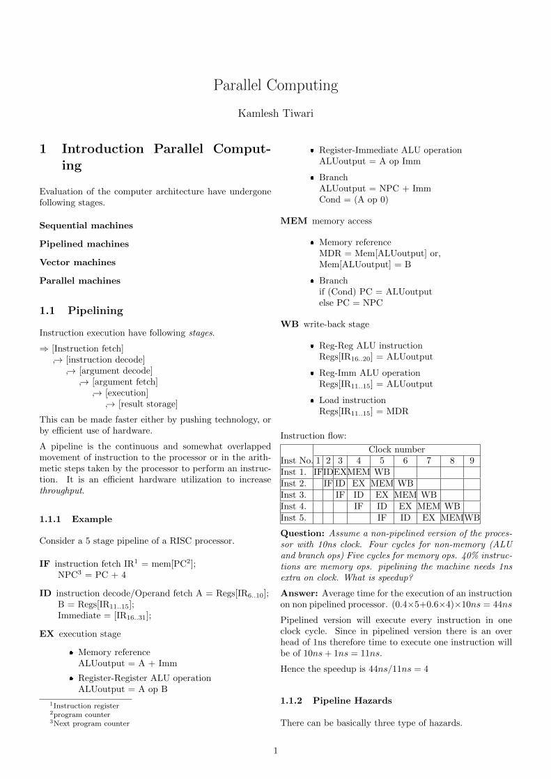
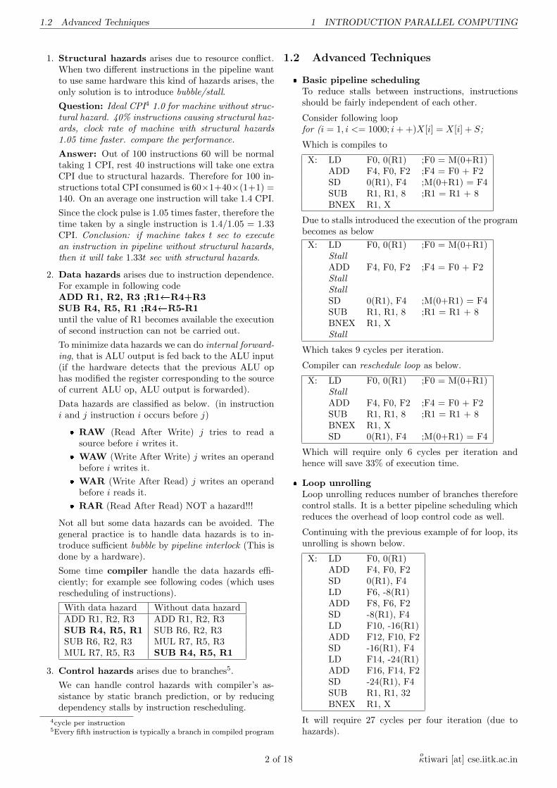
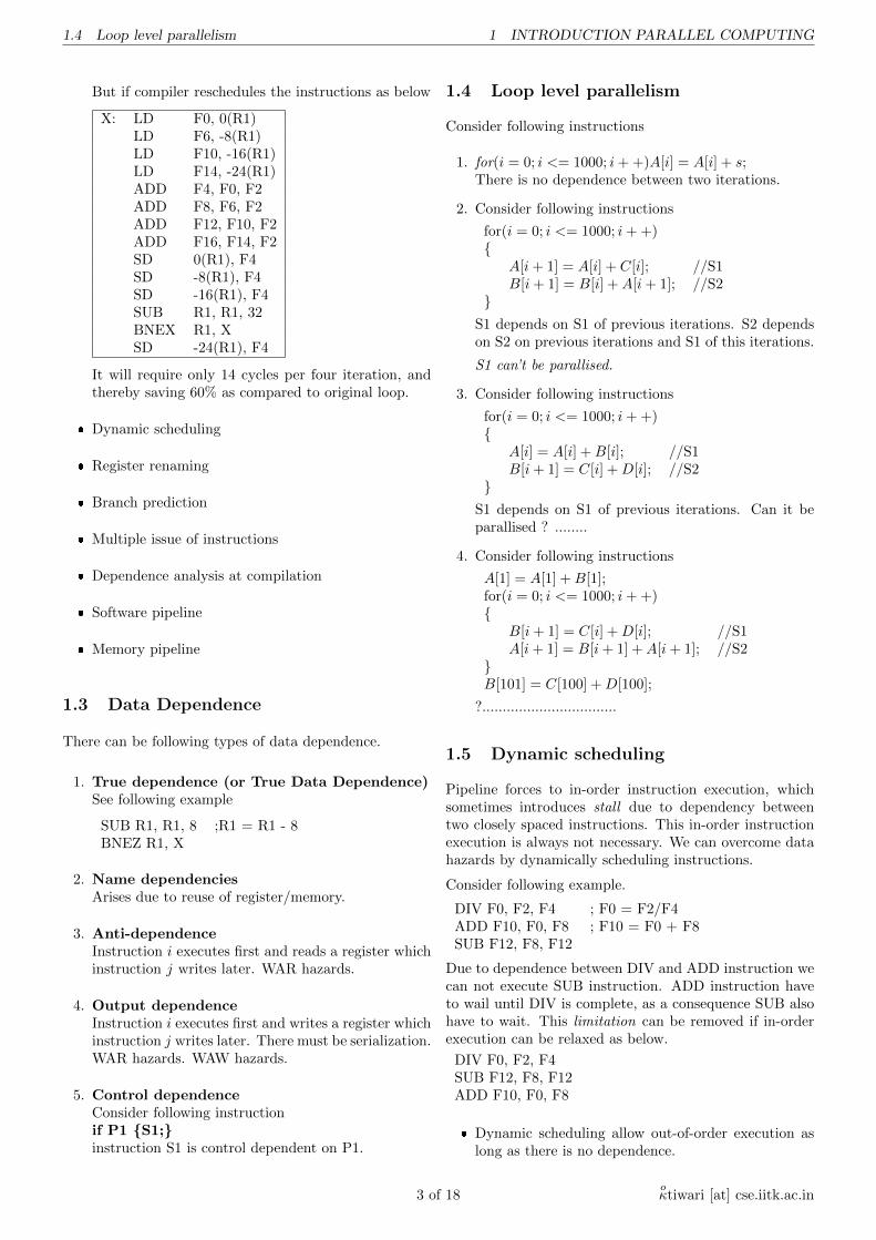
Instruction flow:
Clock numberInst No. 1 2 3 4 5 6 7 8 9Inst 1. IFIDEXMEM WBInst 2. IF ID EX MEM WBInst 3. IF ID EX MEM WBInst 4. IF ID EX MEM WBInst 5. IF ID EX MEMWB
Question: Assume a non-pipelined version of the proces-sor with 10ns clock. Four cycles for non-memory (ALUand branch ops) Five cycles for memory ops. 40% instruc-tions are memory ops. pipelining the machine needs 1nsextra on clock. What is speedup?
Answer: Average time for the execution of an instructionon non pipelined processor. (0.4×5+0.6×4)×10ns = 44ns
Pipelined version will execute every instruction in oneclock cycle. Since in pipelined version there is an overhead of 1ns therefore time to execute one instruction willbe of 10ns+ 1ns = 11ns.
Hence the speedup is 44ns/11ns = 4
1.1.2 Pipeline Hazards
There can be basically three type of hazards.
1
1.2 Advanced Techniques 1 INTRODUCTION PARALLEL COMPUTING
1. Structural hazards arises due to resource conflict.When two different instructions in the pipeline wantto use same hardware this kind of hazards arises, theonly solution is to introduce bubble/stall.
Question: Ideal CPI4 1.0 for machine without struc-tural hazard. 40% instructions causing structural haz-ards, clock rate of machine with structural hazards1.05 time faster. compare the performance.
Answer: Out of 100 instructions 60 will be normaltaking 1 CPI, rest 40 instructions will take one extraCPI due to structural hazards. Therefore for 100 in-structions total CPI consumed is 60×1+40×(1+1) =140. On an average one instruction will take 1.4 CPI.
Since the clock pulse is 1.05 times faster, therefore thetime taken by a single instruction is 1.4/1.05 = 1.33CPI. Conclusion: if machine takes t sec to executean instruction in pipeline without structural hazards,then it will take 1.33t sec with structural hazards.
2. Data hazards arises due to instruction dependence.For example in following codeADD R1, R2, R3 ;R1�R4+R3SUB R4, R5, R1 ;R4�R5-R1until the value of R1 becomes available the executionof second instruction can not be carried out.
To minimize data hazards we can do internal forward-ing, that is ALU output is fed back to the ALU input(if the hardware detects that the previous ALU ophas modified the register corresponding to the sourceof current ALU op, ALU output is forwarded).
Data hazards are classified as below. (in instructioni and j instruction i occurs before j)
� RAW (Read After Write) j tries to read asource before i writes it.
� WAW (Write After Write) j writes an operandbefore i writes it.
� WAR (Write After Read) j writes an operandbefore i reads it.
� RAR (Read After Read) NOT a hazard!!!
Not all but some data hazards can be avoided. Thegeneral practice is to handle data hazards is to in-troduce sufficient bubble by pipeline interlock (This isdone by a hardware).
Some time compiler handle the data hazards effi-ciently; for example see following codes (which usesrescheduling of instructions).
With data hazard Without data hazardADD R1, R2, R3 ADD R1, R2, R3SUB R4, R5, R1 SUB R6, R2, R3SUB R6, R2, R3 MUL R7, R5, R3MUL R7, R5, R3 SUB R4, R5, R1
3. Control hazards arises due to branches5.
We can handle control hazards with compiler’s as-sistance by static branch prediction, or by reducingdependency stalls by instruction rescheduling.
4cycle per instruction5Every fifth instruction is typically a branch in compiled program
1.2 Advanced Techniques
� Basic pipeline schedulingTo reduce stalls between instructions, instructionsshould be fairly independent of each other.
Consider following loopfor (i = 1, i <= 1000; i+ +)X[i] = X[i] + S;
Which is compiles to
X: LD F0, 0(R1) ;F0 = M(0+R1)ADD F4, F0, F2 ;F4 = F0 + F2SD 0(R1), F4 ;M(0+R1) = F4SUB R1, R1, 8 ;R1 = R1 + 8BNEX R1, X
Due to stalls introduced the execution of the programbecomes as below
X: LD F0, 0(R1) ;F0 = M(0+R1)StallADD F4, F0, F2 ;F4 = F0 + F2StallStallSD 0(R1), F4 ;M(0+R1) = F4SUB R1, R1, 8 ;R1 = R1 + 8BNEX R1, XStall
Which takes 9 cycles per iteration.
Compiler can reschedule loop as below.
X: LD F0, 0(R1) ;F0 = M(0+R1)StallADD F4, F0, F2 ;F4 = F0 + F2SUB R1, R1, 8 ;R1 = R1 + 8BNEX R1, XSD 0(R1), F4 ;M(0+R1) = F4
Which will require only 6 cycles per iteration andhence will save 33% of execution time.
� Loop unrollingLoop unrolling reduces number of branches thereforecontrol stalls. It is a better pipeline scheduling whichreduces the overhead of loop control code as well.
Continuing with the previous example of for loop, itsunrolling is shown below.
X: LD F0, 0(R1)ADD F4, F0, F2SD 0(R1), F4LD F6, -8(R1)ADD F8, F6, F2SD -8(R1), F4LD F10, -16(R1)ADD F12, F10, F2SD -16(R1), F4LD F14, -24(R1)ADD F16, F14, F2SD -24(R1), F4SUB R1, R1, 32BNEX R1, X
It will require 27 cycles per four iteration (due tohazards).
2 of 18oκtiwari [at] cse.iitk.ac.in
1.4 Loop level parallelism 1 INTRODUCTION PARALLEL COMPUTING
But if compiler reschedules the instructions as below
X: LD F0, 0(R1)LD F6, -8(R1)LD F10, -16(R1)LD F14, -24(R1)ADD F4, F0, F2ADD F8, F6, F2ADD F12, F10, F2ADD F16, F14, F2SD 0(R1), F4SD -8(R1), F4SD -16(R1), F4SUB R1, R1, 32BNEX R1, XSD -24(R1), F4
It will require only 14 cycles per four iteration, andthereby saving 60% as compared to original loop.
� Dynamic scheduling
� Register renaming
� Branch prediction
� Multiple issue of instructions
� Dependence analysis at compilation
� Software pipeline
� Memory pipeline
1.3 Data Dependence
There can be following types of data dependence.
1. True dependence (or True Data Dependence)See following example
SUB R1, R1, 8 ;R1 = R1 - 8BNEZ R1, X
2. Name dependenciesArises due to reuse of register/memory.
3. Anti-dependenceInstruction i executes first and reads a register whichinstruction j writes later. WAR hazards.
4. Output dependenceInstruction i executes first and writes a register whichinstruction j writes later. There must be serialization.WAR hazards. WAW hazards.
5. Control dependenceConsider following instructionif P1 {S1;}instruction S1 is control dependent on P1.
1.4 Loop level parallelism
Consider following instructions
1. for(i = 0; i <= 1000; i+ +)A[i] = A[i] + s;There is no dependence between two iterations.
2. Consider following instructions
for(i = 0; i <= 1000; i+ +){
A[i+ 1] = A[i] + C[i]; //S1B[i+ 1] = B[i] +A[i+ 1]; //S2
}S1 depends on S1 of previous iterations. S2 dependson S2 on previous iterations and S1 of this iterations.
S1 can’t be parallised.
3. Consider following instructions
for(i = 0; i <= 1000; i+ +){
A[i] = A[i] +B[i]; //S1B[i+ 1] = C[i] +D[i]; //S2
}S1 depends on S1 of previous iterations. Can it beparallised ? ........
4. Consider following instructions
A[1] = A[1] +B[1];for(i = 0; i <= 1000; i+ +){
B[i+ 1] = C[i] +D[i]; //S1A[i+ 1] = B[i+ 1] +A[i+ 1]; //S2
}B[101] = C[100] +D[100];
?.................................
1.5 Dynamic scheduling
Pipeline forces to in-order instruction execution, whichsometimes introduces stall due to dependency betweentwo closely spaced instructions. This in-order instructionexecution is always not necessary. We can overcome datahazards by dynamically scheduling instructions.
Consider following example.
DIV F0, F2, F4 ; F0 = F2/F4ADD F10, F0, F8 ; F10 = F0 + F8SUB F12, F8, F12
Due to dependence between DIV and ADD instruction wecan not execute SUB instruction. ADD instruction haveto wail until DIV is complete, as a consequence SUB alsohave to wait. This limitation can be removed if in-orderexecution can be relaxed as below.
DIV F0, F2, F4SUB F12, F8, F12ADD F10, F0, F8
� Dynamic scheduling allow out-of-order execution aslong as there is no dependence.
3 of 18oκtiwari [at] cse.iitk.ac.in
1.5 Dynamic scheduling 1 INTRODUCTION PARALLEL COMPUTING
� Issue instructions in-order
� Instruction begins execution as soon as their dataoperands are available.
� Split ID pipeline stage into.
– Issue - Decode instruction and check for struc-tural hazards.
– Read operands - wait until no data hazards,then read operands.
1.5.1 Dynamic scheduling with Score-boarding
Score-boarding allows the out-of-order execution whenthere are enough resources and no data dependence. Everyinstruction goes through scoreboard. Scoreboard keepstrack of data dependence and decides when an instructioncan read operands and begin execution.
In case, instruction can’t begin execution immediately, itmonitors the changes in hardware and decides when aninstruction can begin execution. It also decides when aninstruction can write its results.
Steps of Execution:
� Issue:Functional unit needed by instruction is free and noother active instruction has same destination register.Avoids WAW hazard.
� Read Operands:A source operand is available if no earlier issued ac-tive instruction is going to write it or if the registercontaining the operand is being written by a currentlyactive functional unit. RAW hazards are resolved andout-of-order execution may take place.
� Execution:The functional unit begins execution and notifiesscoreboard on completion.
� Write result:Scoreboard permits the writing only after it ensuresthat no WAR hazard will take place. A completinginstruction cant be permitted to write the results if
– There is an instruction that has not read itsoperands that precedes the completing instruc-tion.
– One of the operands is the same register as theresult of the completing instruction.
Scoreboard doesnt take advantage of internal forwarding.It has also to take care of number of buses available fordata transfer.
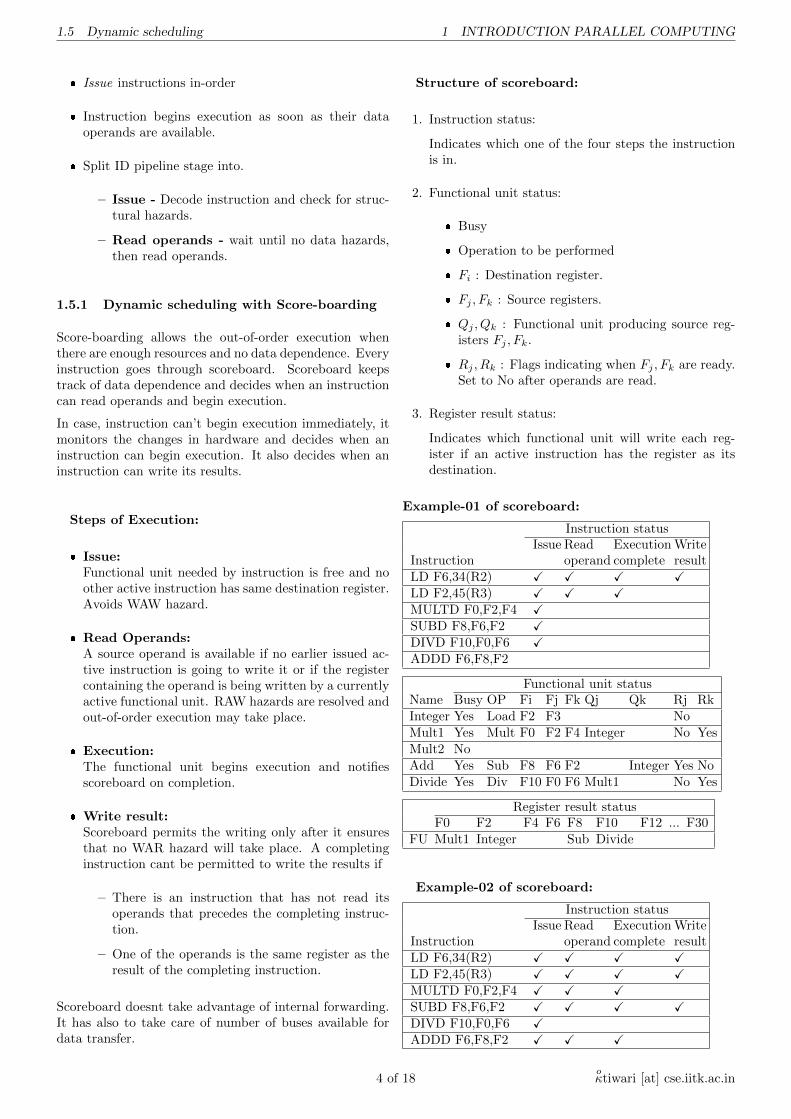
Structure of scoreboard:
1. Instruction status:
Indicates which one of the four steps the instructionis in.
2. Functional unit status:
� Busy
� Operation to be performed
� Fi : Destination register.
� Fj , Fk : Source registers.
� Qj , Qk : Functional unit producing source reg-isters Fj , Fk.
� Rj , Rk : Flags indicating when Fj , Fk are ready.Set to No after operands are read.
3. Register result status:
Indicates which functional unit will write each reg-ister if an active instruction has the register as itsdestination.
Example-01 of scoreboard:
Instruction statusIssue Read Execution Write
Instruction operand complete resultLD F6,34(R2) X X X XLD F2,45(R3) X X XMULTD F0,F2,F4 XSUBD F8,F6,F2 XDIVD F10,F0,F6 XADDD F6,F8,F2
Functional unit statusName Busy OP Fi Fj Fk Qj Qk Rj RkInteger Yes Load F2 F3 NoMult1 Yes Mult F0 F2 F4 Integer No YesMult2 NoAdd Yes Sub F8 F6 F2 Integer Yes NoDivide Yes Div F10 F0 F6 Mult1 No Yes
Register result statusF0 F2 F4 F6 F8 F10 F12 ... F30
FU Mult1 Integer Sub Divide
Example-02 of scoreboard:
Instruction statusIssue Read Execution Write
Instruction operand complete resultLD F6,34(R2) X X X XLD F2,45(R3) X X X XMULTD F0,F2,F4 X X XSUBD F8,F6,F2 X X X XDIVD F10,F0,F6 XADDD F6,F8,F2 X X X
4 of 18oκtiwari [at] cse.iitk.ac.in
1.5 Dynamic scheduling 1 INTRODUCTION PARALLEL COMPUTING
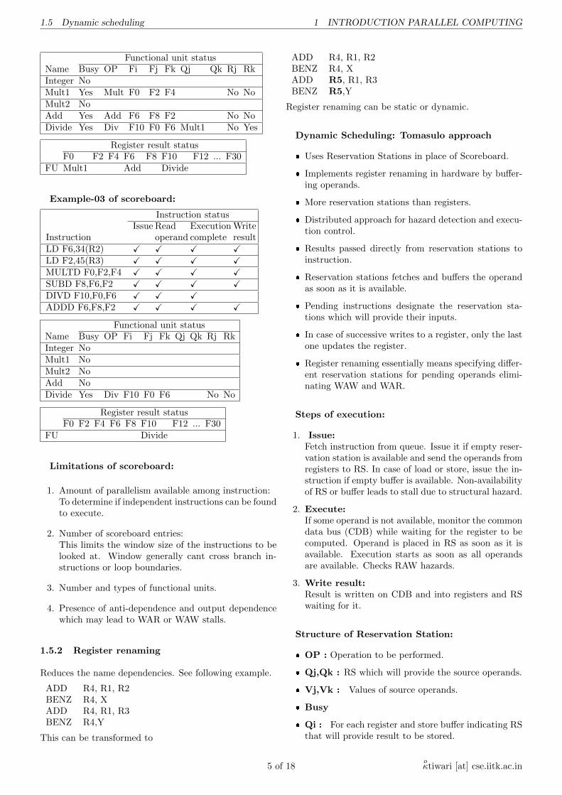
Functional unit statusName Busy OP Fi Fj Fk Qj Qk Rj RkInteger NoMult1 Yes Mult F0 F2 F4 No NoMult2 NoAdd Yes Add F6 F8 F2 No NoDivide Yes Div F10 F0 F6 Mult1 No Yes
Register result statusF0 F2 F4 F6 F8 F10 F12 ... F30
FU Mult1 Add Divide
Example-03 of scoreboard:
Instruction statusIssue Read Execution Write
Instruction operand complete resultLD F6,34(R2) X X X XLD F2,45(R3) X X X XMULTD F0,F2,F4 X X X XSUBD F8,F6,F2 X X X XDIVD F10,F0,F6 X X XADDD F6,F8,F2 X X X X
Functional unit statusName Busy OP Fi Fj Fk Qj Qk Rj RkInteger NoMult1 NoMult2 NoAdd NoDivide Yes Div F10 F0 F6 No No
Register result statusF0 F2 F4 F6 F8 F10 F12 ... F30
FU Divide
Limitations of scoreboard:
1. Amount of parallelism available among instruction:To determine if independent instructions can be foundto execute.
2. Number of scoreboard entries:This limits the window size of the instructions to belooked at. Window generally cant cross branch in-structions or loop boundaries.
3. Number and types of functional units.
4. Presence of anti-dependence and output dependencewhich may lead to WAR or WAW stalls.
1.5.2 Register renaming
Reduces the name dependencies. See following example.
ADD R4, R1, R2BENZ R4, XADD R4, R1, R3BENZ R4,Y
This can be transformed to
ADD R4, R1, R2BENZ R4, XADD R5, R1, R3BENZ R5,Y
Register renaming can be static or dynamic.
Dynamic Scheduling: Tomasulo approach
� Uses Reservation Stations in place of Scoreboard.
� Implements register renaming in hardware by buffer-ing operands.
� More reservation stations than registers.
� Distributed approach for hazard detection and execu-tion control.
� Results passed directly from reservation stations toinstruction.
� Reservation stations fetches and buffers the operandas soon as it is available.
� Pending instructions designate the reservation sta-tions which will provide their inputs.
� In case of successive writes to a register, only the lastone updates the register.
� Register renaming essentially means specifying differ-ent reservation stations for pending operands elimi-nating WAW and WAR.
Steps of execution:
1. Issue:Fetch instruction from queue. Issue it if empty reser-vation station is available and send the operands fromregisters to RS. In case of load or store, issue the in-struction if empty buffer is available. Non-availabilityof RS or buffer leads to stall due to structural hazard.
2. Execute:If some operand is not available, monitor the commondata bus (CDB) while waiting for the register to becomputed. Operand is placed in RS as soon as it isavailable. Execution starts as soon as all operandsare available. Checks RAW hazards.
3. Write result:Result is written on CDB and into registers and RSwaiting for it.
Structure of Reservation Station:
� OP : Operation to be performed.
� Qj,Qk : RS which will provide the source operands.
� Vj,Vk : Values of source operands.
� Busy
� Qi : For each register and store buffer indicating RSthat will provide result to be stored.
5 of 18oκtiwari [at] cse.iitk.ac.in
1.6 Branch Prediction 1 INTRODUCTION PARALLEL COMPUTING
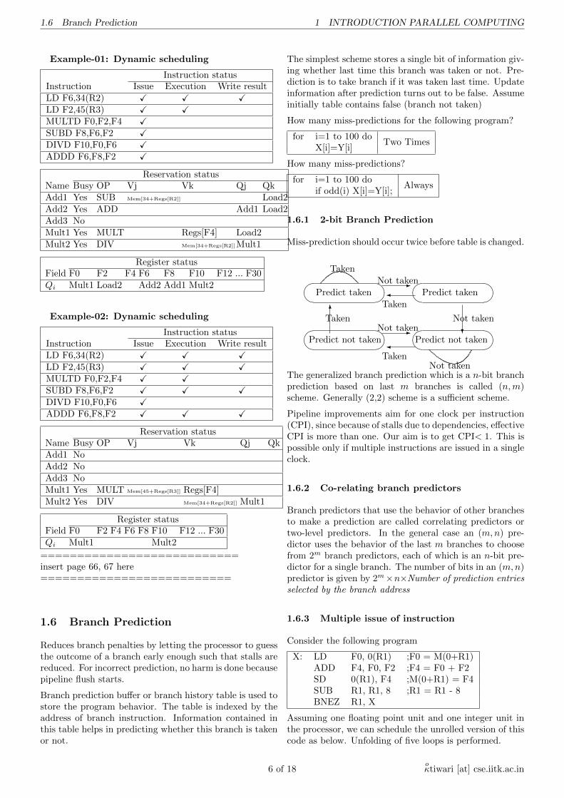
Example-01: Dynamic scheduling
Instruction statusInstruction Issue Execution Write resultLD F6,34(R2) X X XLD F2,45(R3) X XMULTD F0,F2,F4 XSUBD F8,F6,F2 XDIVD F10,F0,F6 XADDD F6,F8,F2 X
Reservation statusName Busy OP Vj Vk Qj QkAdd1 Yes SUB Mem[34+Regs[R2]] Load2Add2 Yes ADD Add1 Load2Add3 NoMult1 Yes MULT Regs[F4] Load2Mult2 Yes DIV Mem[34+Regs[R2]]Mult1
Register statusField F0 F2 F4 F6 F8 F10 F12 ... F30Qi Mult1 Load2 Add2 Add1 Mult2
Example-02: Dynamic scheduling
Instruction statusInstruction Issue Execution Write resultLD F6,34(R2) X X XLD F2,45(R3) X X XMULTD F0,F2,F4 X XSUBD F8,F6,F2 X X XDIVD F10,F0,F6 XADDD F6,F8,F2 X X X
Reservation statusName Busy OP Vj Vk Qj QkAdd1 NoAdd2 NoAdd3 NoMult1 Yes MULT Mem[45+Regs[R3]] Regs[F4]Mult2 Yes DIV Mem[34+Regs[R2]] Mult1
Register statusField F0 F2 F4 F6 F8 F10 F12 ... F30Qi Mult1 Mult2
===========================insert page 66, 67 here==========================
1.6 Branch Prediction
Reduces branch penalties by letting the processor to guessthe outcome of a branch early enough such that stalls arereduced. For incorrect prediction, no harm is done becausepipeline flush starts.
Branch prediction buffer or branch history table is used tostore the program behavior. The table is indexed by theaddress of branch instruction. Information contained inthis table helps in predicting whether this branch is takenor not.
The simplest scheme stores a single bit of information giv-ing whether last time this branch was taken or not. Pre-diction is to take branch if it was taken last time. Updateinformation after prediction turns out to be false. Assumeinitially table contains false (branch not taken)
How many miss-predictions for the following program?
for i=1 to 100 doTwo Times
X[i]=Y[i]
How many miss-predictions?
for i=1 to 100 doAlways
if odd(i) X[i]=Y[i];
1.6.1 2-bit Branch Prediction
Miss-prediction should occur twice before table is changed.
�� ��Predict not taken
�� ��Predict taken
�� ��Predict not taken
�� ��Predict taken
-Not taken
-Not taken
?
Not taken
�
Taken
�
Taken6
Taken
Not taken
Taken
The generalized branch prediction which is a n-bit branchprediction based on last m branches is called (n,m)scheme. Generally (2,2) scheme is a sufficient scheme.
Pipeline improvements aim for one clock per instruction(CPI), since because of stalls due to dependencies, effectiveCPI is more than one. Our aim is to get CPI< 1. This ispossible only if multiple instructions are issued in a singleclock.
1.6.2 Co-relating branch predictors
Branch predictors that use the behavior of other branchesto make a prediction are called correlating predictors ortwo-level predictors. In the general case an (m,n) pre-dictor uses the behavior of the last m branches to choosefrom 2m branch predictors, each of which is an n-bit pre-dictor for a single branch. The number of bits in an (m,n)predictor is given by 2m×n×Number of prediction entriesselected by the branch address
1.6.3 Multiple issue of instruction
Consider the following program
X: LD F0, 0(R1) ;F0 = M(0+R1)ADD F4, F0, F2 ;F4 = F0 + F2SD 0(R1), F4 ;M(0+R1) = F4SUB R1, R1, 8 ;R1 = R1 - 8BNEZ R1, X
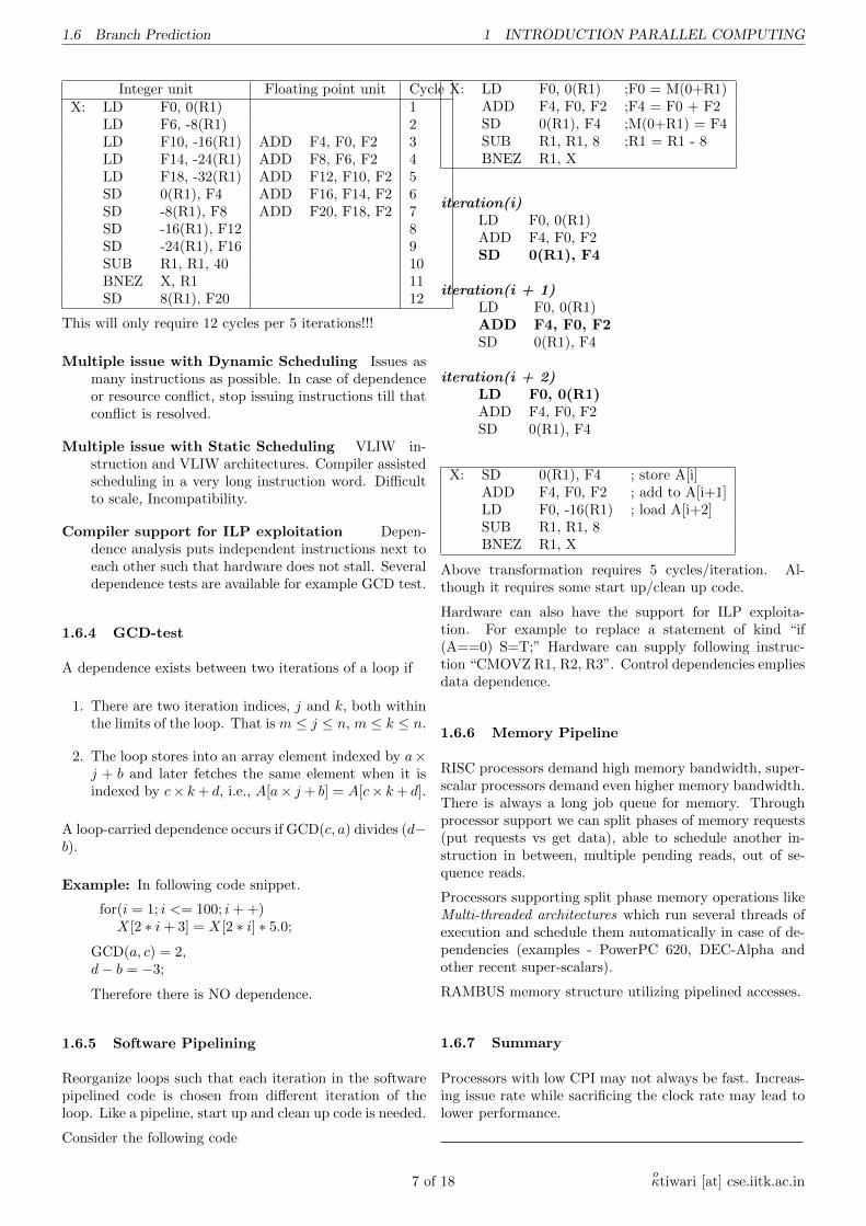
Assuming one floating point unit and one integer unit inthe processor, we can schedule the unrolled version of thiscode as below. Unfolding of five loops is performed.
6 of 18oκtiwari [at] cse.iitk.ac.in
1.6 Branch Prediction 1 INTRODUCTION PARALLEL COMPUTING
Integer unit Floating point unit CycleX: LD F0, 0(R1) 1
LD F6, -8(R1) 2LD F10, -16(R1) ADD F4, F0, F2 3LD F14, -24(R1) ADD F8, F6, F2 4LD F18, -32(R1) ADD F12, F10, F2 5SD 0(R1), F4 ADD F16, F14, F2 6SD -8(R1), F8 ADD F20, F18, F2 7SD -16(R1), F12 8SD -24(R1), F16 9SUB R1, R1, 40 10BNEZ X, R1 11SD 8(R1), F20 12
This will only require 12 cycles per 5 iterations!!!
Multiple issue with Dynamic Scheduling Issues asmany instructions as possible. In case of dependenceor resource conflict, stop issuing instructions till thatconflict is resolved.
Multiple issue with Static Scheduling VLIW in-struction and VLIW architectures. Compiler assistedscheduling in a very long instruction word. Difficultto scale, Incompatibility.
Compiler support for ILP exploitation Depen-dence analysis puts independent instructions next toeach other such that hardware does not stall. Severaldependence tests are available for example GCD test.
1.6.4 GCD-test
A dependence exists between two iterations of a loop if
1. There are two iteration indices, j and k, both withinthe limits of the loop. That is m ≤ j ≤ n, m ≤ k ≤ n.
2. The loop stores into an array element indexed by a×j + b and later fetches the same element when it isindexed by c× k+ d, i.e., A[a× j + b] = A[c× k+ d].
A loop-carried dependence occurs if GCD(c, a) divides (d−b).
Example: In following code snippet.
for(i = 1; i <= 100; i+ +)X[2 ∗ i+ 3] = X[2 ∗ i] ∗ 5.0;
GCD(a, c) = 2,d− b = −3;
Therefore there is NO dependence.
1.6.5 Software Pipelining
Reorganize loops such that each iteration in the softwarepipelined code is chosen from different iteration of theloop. Like a pipeline, start up and clean up code is needed.
Consider the following code
X: LD F0, 0(R1) ;F0 = M(0+R1)ADD F4, F0, F2 ;F4 = F0 + F2SD 0(R1), F4 ;M(0+R1) = F4SUB R1, R1, 8 ;R1 = R1 - 8BNEZ R1, X
iteration(i)LD F0, 0(R1)ADD F4, F0, F2SD 0(R1), F4
iteration(i + 1)LD F0, 0(R1)ADD F4, F0, F2SD 0(R1), F4
iteration(i + 2)LD F0, 0(R1)ADD F4, F0, F2SD 0(R1), F4
X: SD 0(R1), F4 ; store A[i]ADD F4, F0, F2 ; add to A[i+1]LD F0, -16(R1) ; load A[i+2]SUB R1, R1, 8BNEZ R1, X
Above transformation requires 5 cycles/iteration. Al-though it requires some start up/clean up code.
Hardware can also have the support for ILP exploita-tion. For example to replace a statement of kind “if(A==0) S=T;” Hardware can supply following instruc-tion “CMOVZ R1, R2, R3”. Control dependencies empliesdata dependence.
1.6.6 Memory Pipeline
RISC processors demand high memory bandwidth, super-scalar processors demand even higher memory bandwidth.There is always a long job queue for memory. Throughprocessor support we can split phases of memory requests(put requests vs get data), able to schedule another in-struction in between, multiple pending reads, out of se-quence reads.
Processors supporting split phase memory operations likeMulti-threaded architectures which run several threads ofexecution and schedule them automatically in case of de-pendencies (examples - PowerPC 620, DEC-Alpha andother recent super-scalars).
RAMBUS memory structure utilizing pipelined accesses.
1.6.7 Summary
Processors with low CPI may not always be fast. Increas-ing issue rate while sacrificing the clock rate may lead tolower performance.
7 of 18oκtiwari [at] cse.iitk.ac.in
2.2 Sementec Attributes 2 SCALABLE COMPUTER ARCHITECTURE
2 Scalable computer architecture
Scaling-up refers to improving the computer resourcesto accommodate performance and functionality demand.Scaling-down is done to reduce cast. Scaling-up may in-clude
� Functionality and performance.
� Scaling in cast
� Compatibility
Common Architectures for scalable parallel computers are
Shared nothing architecture: Macro architecture.
Shared disk architecture:
Shared memory architecture: Micro architecture.
Advantages: size scalability, resource scalability, softwarescalability, memory scalability, scalability in problem size,generation scalability, space scalabiliy, hetrogenity scala-bility.
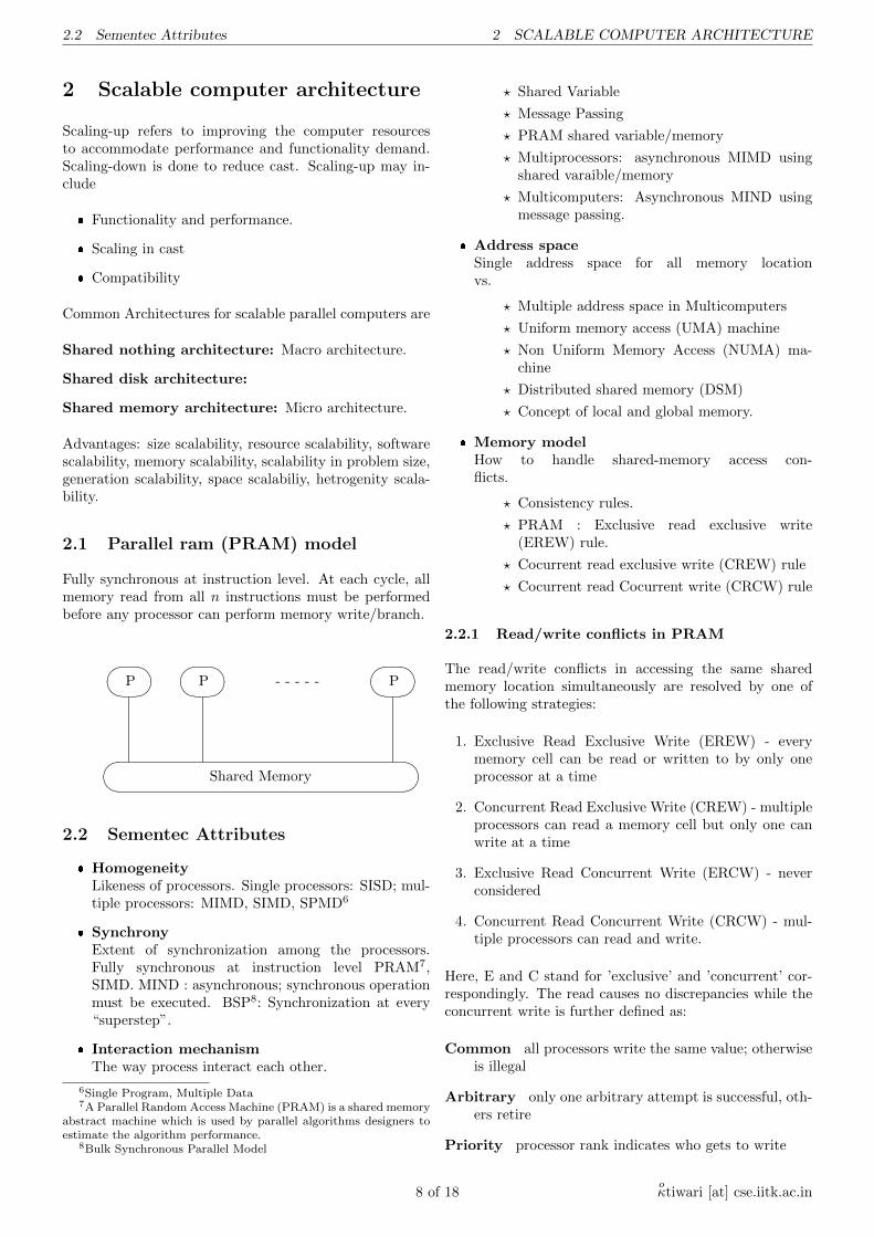
2.1 Parallel ram (PRAM) model
Fully synchronous at instruction level. At each cycle, allmemory read from all n instructions must be performedbefore any processor can perform memory write/branch.
�� ��Shared Memory
�� ��P�� ��P
�� ��P- - - - -
2.2 Sementec Attributes
� HomogeneityLikeness of processors. Single processors: SISD; mul-tiple processors: MIMD, SIMD, SPMD6
� SynchronyExtent of synchronization among the processors.Fully synchronous at instruction level PRAM7,SIMD. MIND : asynchronous; synchronous operationmust be executed. BSP8: Synchronization at every“superstep”.
� Interaction mechanismThe way process interact each other.
6Single Program, Multiple Data7A Parallel Random Access Machine (PRAM) is a shared memory
abstract machine which is used by parallel algorithms designers toestimate the algorithm performance.
8Bulk Synchronous Parallel Model
? Shared Variable
? Message Passing
? PRAM shared variable/memory
? Multiprocessors: asynchronous MIMD usingshared varaible/memory
? Multicomputers: Asynchronous MIND usingmessage passing.
� Address spaceSingle address space for all memory locationvs.
? Multiple address space in Multicomputers
? Uniform memory access (UMA) machine
? Non Uniform Memory Access (NUMA) ma-chine
? Distributed shared memory (DSM)
? Concept of local and global memory.
� Memory modelHow to handle shared-memory access con-flicts.
? Consistency rules.
? PRAM : Exclusive read exclusive write(EREW) rule.
? Cocurrent read exclusive write (CREW) rule
? Cocurrent read Cocurrent write (CRCW) rule
2.2.1 Read/write conflicts in PRAM
The read/write conflicts in accessing the same sharedmemory location simultaneously are resolved by one ofthe following strategies:
1. Exclusive Read Exclusive Write (EREW) - everymemory cell can be read or written to by only oneprocessor at a time
2. Concurrent Read Exclusive Write (CREW) - multipleprocessors can read a memory cell but only one canwrite at a time
3. Exclusive Read Concurrent Write (ERCW) - neverconsidered
4. Concurrent Read Concurrent Write (CRCW) - mul-tiple processors can read and write.
Here, E and C stand for ’exclusive’ and ’concurrent’ cor-respondingly. The read causes no discrepancies while theconcurrent write is further defined as:
Common all processors write the same value; otherwiseis illegal
Arbitrary only one arbitrary attempt is successful, oth-ers retire
Priority processor rank indicates who gets to write
8 of 18oκtiwari [at] cse.iitk.ac.in
2.3 Flynn’s classification 2 SCALABLE COMPUTER ARCHITECTURE
2.3 Flynn’s classification
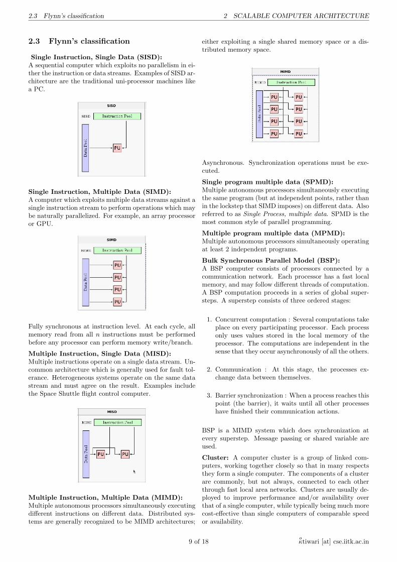
Single Instruction, Single Data (SISD):A sequential computer which exploits no parallelism in ei-ther the instruction or data streams. Examples of SISD ar-chitecture are the traditional uni-processor machines likea PC.
Single Instruction, Multiple Data (SIMD):A computer which exploits multiple data streams against asingle instruction stream to perform operations which maybe naturally parallelized. For example, an array processoror GPU.
Fully synchronous at instruction level. At each cycle, allmemory read from all n instructions must be performedbefore any processor can perform memory write/branch.
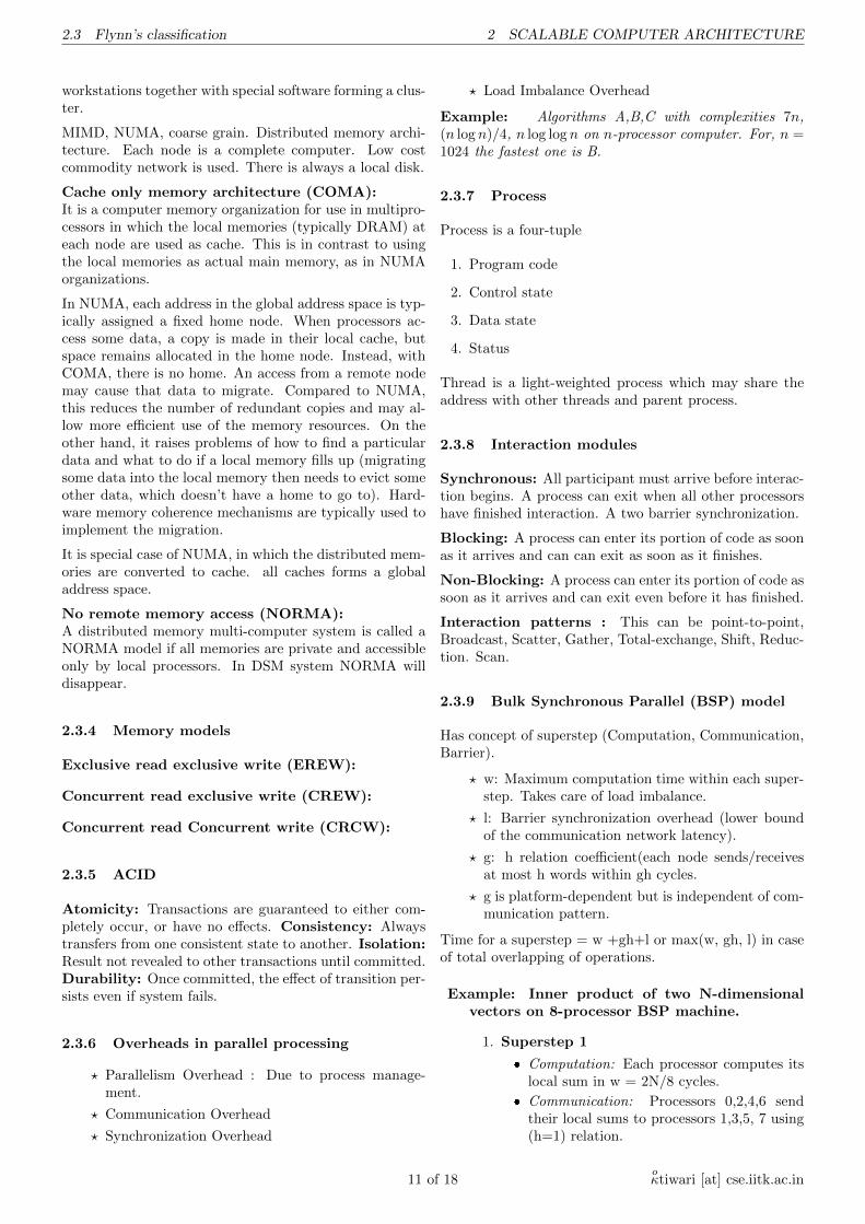
Multiple Instruction, Single Data (MISD):Multiple instructions operate on a single data stream. Un-common architecture which is generally used for fault tol-erance. Heterogeneous systems operate on the same datastream and must agree on the result. Examples includethe Space Shuttle flight control computer.
Multiple Instruction, Multiple Data (MIMD):Multiple autonomous processors simultaneously executingdifferent instructions on different data. Distributed sys-tems are generally recognized to be MIMD architectures;
either exploiting a single shared memory space or a dis-tributed memory space.
Asynchronous. Synchronization operations must be exe-cuted.
Single program multiple data (SPMD):Multiple autonomous processors simultaneously executingthe same program (but at independent points, rather thanin the lockstep that SIMD imposes) on different data. Alsoreferred to as Single Process, multiple data. SPMD is themost common style of parallel programming.
Multiple program multiple data (MPMD):Multiple autonomous processors simultaneously operatingat least 2 independent programs.
Bulk Synchronous Parallel Model (BSP):A BSP computer consists of processors connected by acommunication network. Each processor has a fast localmemory, and may follow different threads of computation.A BSP computation proceeds in a series of global super-steps. A superstep consists of three ordered stages:
1. Concurrent computation : Several computations takeplace on every participating processor. Each processonly uses values stored in the local memory of theprocessor. The computations are independent in thesense that they occur asynchronously of all the others.
2. Communication : At this stage, the processes ex-change data between themselves.
3. Barrier synchronization : When a process reaches thispoint (the barrier), it waits until all other processeshave finished their communication actions.
BSP is a MIMD system which does synchronization atevery superstep. Message passing or shared variable areused.
Cluster: A computer cluster is a group of linked com-puters, working together closely so that in many respectsthey form a single computer. The components of a clusterare commonly, but not always, connected to each otherthrough fast local area networks. Clusters are usually de-ployed to improve performance and/or availability overthat of a single computer, while typically being much morecost-effective than single computers of comparable speedor availability.
9 of 18oκtiwari [at] cse.iitk.ac.in
2.3 Flynn’s classification 2 SCALABLE COMPUTER ARCHITECTURE
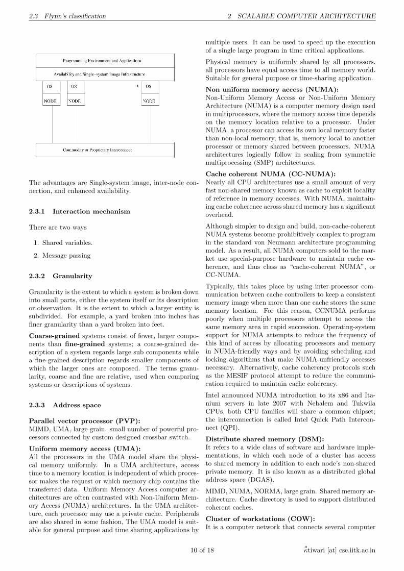
The advantages are Single-system image, inter-node con-nection, and enhanced availability.
2.3.1 Interaction mechanism
There are two ways
1. Shared variables.
2. Message passing
2.3.2 Granularity
Granularity is the extent to which a system is broken downinto small parts, either the system itself or its descriptionor observation. It is the extent to which a larger entity issubdivided. For example, a yard broken into inches hasfiner granularity than a yard broken into feet.
Coarse-grained systems consist of fewer, larger compo-nents than fine-grained systems; a coarse-grained de-scription of a system regards large sub components whilea fine-grained description regards smaller components ofwhich the larger ones are composed. The terms granu-larity, coarse and fine are relative, used when comparingsystems or descriptions of systems.
2.3.3 Address space
Parallel vector processor (PVP):MIMD, UMA, large grain. small number of powerful pro-cessors connected by custom designed crossbar switch.
Uniform memory access (UMA):All the processors in the UMA model share the physi-cal memory uniformly. In a UMA architecture, accesstime to a memory location is independent of which proces-sor makes the request or which memory chip contains thetransferred data. Uniform Memory Access computer ar-chitectures are often contrasted with Non-Uniform Mem-ory Access (NUMA) architectures. In the UMA architec-ture, each processor may use a private cache. Peripheralsare also shared in some fashion, The UMA model is suit-able for general purpose and time sharing applications by
multiple users. It can be used to speed up the executionof a single large program in time critical applications.
Physical memory is uniformly shared by all processors.all processors have equal access time to all memory world.Suitable for general purpose or time-sharing application.
Non uniform memory access (NUMA):Non-Uniform Memory Access or Non-Uniform MemoryArchitecture (NUMA) is a computer memory design usedin multiprocessors, where the memory access time dependson the memory location relative to a processor. UnderNUMA, a processor can access its own local memory fasterthan non-local memory, that is, memory local to anotherprocessor or memory shared between processors. NUMAarchitectures logically follow in scaling from symmetricmultiprocessing (SMP) architectures.
Cache coherent NUMA (CC-NUMA):Nearly all CPU architectures use a small amount of veryfast non-shared memory known as cache to exploit localityof reference in memory accesses. With NUMA, maintain-ing cache coherence across shared memory has a significantoverhead.
Although simpler to design and build, non-cache-coherentNUMA systems become prohibitively complex to programin the standard von Neumann architecture programmingmodel. As a result, all NUMA computers sold to the mar-ket use special-purpose hardware to maintain cache co-herence, and thus class as “cache-coherent NUMA”, orCC-NUMA.
Typically, this takes place by using inter-processor com-munication between cache controllers to keep a consistentmemory image when more than one cache stores the samememory location. For this reason, CCNUMA performspoorly when multiple processors attempt to access thesame memory area in rapid succession. Operating-systemsupport for NUMA attempts to reduce the frequency ofthis kind of access by allocating processors and memoryin NUMA-friendly ways and by avoiding scheduling andlocking algorithms that make NUMA-unfriendly accessesnecessary. Alternatively, cache coherency protocols suchas the MESIF protocol attempt to reduce the communi-cation required to maintain cache coherency.
Intel announced NUMA introduction to its x86 and Ita-nium servers in late 2007 with Nehalem and TukwilaCPUs, both CPU families will share a common chipset;the interconnection is called Intel Quick Path Intercon-nect (QPI).
Distribute shared memory (DSM):It refers to a wide class of software and hardware imple-mentations, in which each node of a cluster has accessto shared memory in addition to each node’s non-sharedprivate memory. It is also known as a distributed globaladdress space (DGAS).
MIMD, NUMA, NORMA, large grain. Shared memory ar-chitecture. Cache directory is used to support distributedcoherent caches.
Cluster of workstations (COW):It is a computer network that connects several computer
10 of 18oκtiwari [at] cse.iitk.ac.in
2.3 Flynn’s classification 2 SCALABLE COMPUTER ARCHITECTURE
workstations together with special software forming a clus-ter.
MIMD, NUMA, coarse grain. Distributed memory archi-tecture. Each node is a complete computer. Low costcommodity network is used. There is always a local disk.
Cache only memory architecture (COMA):It is a computer memory organization for use in multipro-cessors in which the local memories (typically DRAM) ateach node are used as cache. This is in contrast to usingthe local memories as actual main memory, as in NUMAorganizations.
In NUMA, each address in the global address space is typ-ically assigned a fixed home node. When processors ac-cess some data, a copy is made in their local cache, butspace remains allocated in the home node. Instead, withCOMA, there is no home. An access from a remote nodemay cause that data to migrate. Compared to NUMA,this reduces the number of redundant copies and may al-low more efficient use of the memory resources. On theother hand, it raises problems of how to find a particulardata and what to do if a local memory fills up (migratingsome data into the local memory then needs to evict someother data, which doesn’t have a home to go to). Hard-ware memory coherence mechanisms are typically used toimplement the migration.
It is special case of NUMA, in which the distributed mem-ories are converted to cache. all caches forms a globaladdress space.
No remote memory access (NORMA):A distributed memory multi-computer system is called aNORMA model if all memories are private and accessibleonly by local processors. In DSM system NORMA willdisappear.
2.3.4 Memory models
Exclusive read exclusive write (EREW):
Concurrent read exclusive write (CREW):
Concurrent read Concurrent write (CRCW):
2.3.5 ACID
Atomicity: Transactions are guaranteed to either com-pletely occur, or have no effects. Consistency: Alwaystransfers from one consistent state to another. Isolation:Result not revealed to other transactions until committed.Durability: Once committed, the effect of transition per-sists even if system fails.
2.3.6 Overheads in parallel processing
? Parallelism Overhead : Due to process manage-ment.
? Communication Overhead
? Synchronization Overhead
? Load Imbalance Overhead
Example: Algorithms A,B,C with complexities 7n,(n log n)/4, n log log n on n-processor computer. For, n =1024 the fastest one is B.
2.3.7 Process
Process is a four-tuple
1. Program code
2. Control state
3. Data state
4. Status
Thread is a light-weighted process which may share theaddress with other threads and parent process.
2.3.8 Interaction modules
Synchronous: All participant must arrive before interac-tion begins. A process can exit when all other processorshave finished interaction. A two barrier synchronization.
Blocking: A process can enter its portion of code as soonas it arrives and can can exit as soon as it finishes.
Non-Blocking: A process can enter its portion of code assoon as it arrives and can exit even before it has finished.
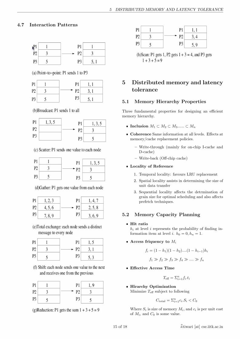
Interaction patterns : This can be point-to-point,Broadcast, Scatter, Gather, Total-exchange, Shift, Reduc-tion. Scan.
2.3.9 Bulk Synchronous Parallel (BSP) model
Has concept of superstep (Computation, Communication,Barrier).
? w: Maximum computation time within each super-step. Takes care of load imbalance.
? l: Barrier synchronization overhead (lower boundof the communication network latency).
? g: h relation coefficient(each node sends/receivesat most h words within gh cycles.
? g is platform-dependent but is independent of com-munication pattern.
Time for a superstep = w +gh+l or max(w, gh, l) in caseof total overlapping of operations.
Example: Inner product of two N-dimensionalvectors on 8-processor BSP machine.
1. Superstep 1
� Computation: Each processor computes itslocal sum in w = 2N/8 cycles.
� Communication: Processors 0,2,4,6 sendtheir local sums to processors 1,3,5, 7 using(h=1) relation.
11 of 18oκtiwari [at] cse.iitk.ac.in
3 PHYSICAL MACHINE MODEL
� Barrier Synchronization
2. Superstep 2
� Computation: processors 1,3,5,7 performone addition (w = 1).
� Communication: Processors 1 and 5 sendtheir local sums to processors 3 and 7 using(h=1) relation.
� Barrier Synchronization
3. Superstep 3
� Computation:Processors 3 and 7 performone addition (w = 1)
� Communication: Processor 3 sends its in-termediate result to processor 7 using (h=1)relation.
� Barrier Synchronization
4. Superstep 4
� Computation: Processor 7 performs one ad-dition (w = 1)
Execution time = 2N/8 + 3g + 3l+ 3 = 2N/n+ (g +l + 1) log n.
2.4 Clusters
Collection of complete computers, physically intercon-nected by a high-performance network.
Features: Cluster Nodes, Single-System Image, Internodeconnection, Enhanced availability, Better Performance.
Benefits and Difficulties of Clusters: Usability, Availabil-ity, Scalable Performance, Performance/Cost Ratio.
Clusters have high availability due to : Processors andMemories, Disk Arrays, Operating System. Clusters arehighly scalable in terms of processors, memories, I/O de-vices and disks.
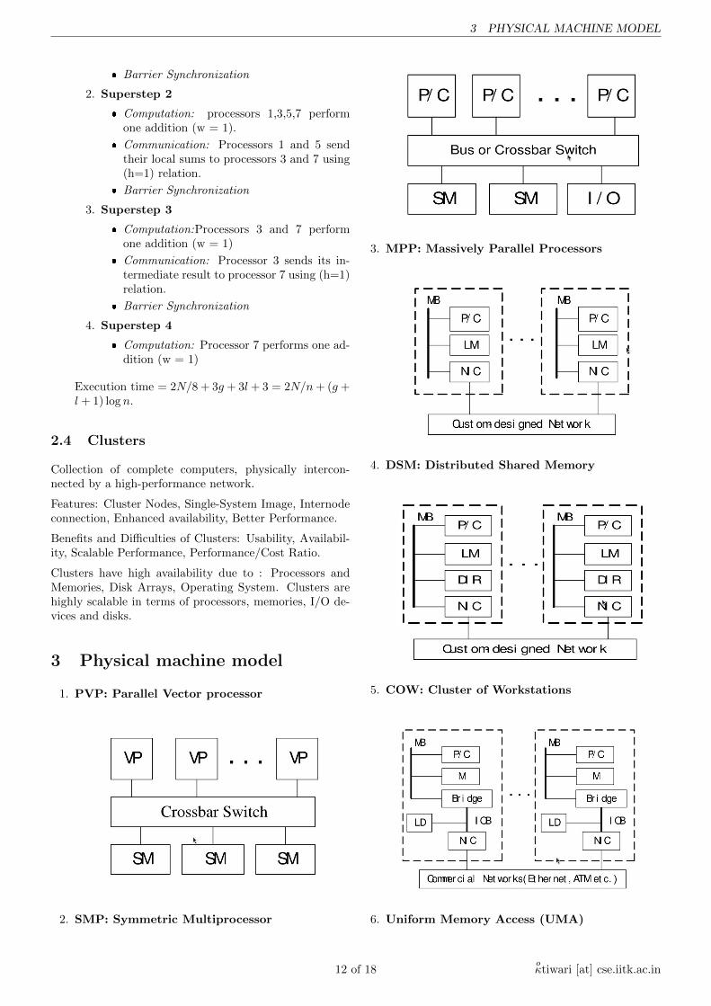
3 Physical machine model
1. PVP: Parallel Vector processor
2. SMP: Symmetric Multiprocessor
3. MPP: Massively Parallel Processors
4. DSM: Distributed Shared Memory
5. COW: Cluster of Workstations
6. Uniform Memory Access (UMA)
12 of 18oκtiwari [at] cse.iitk.ac.in
4 PARELLEL PROGRAMMING
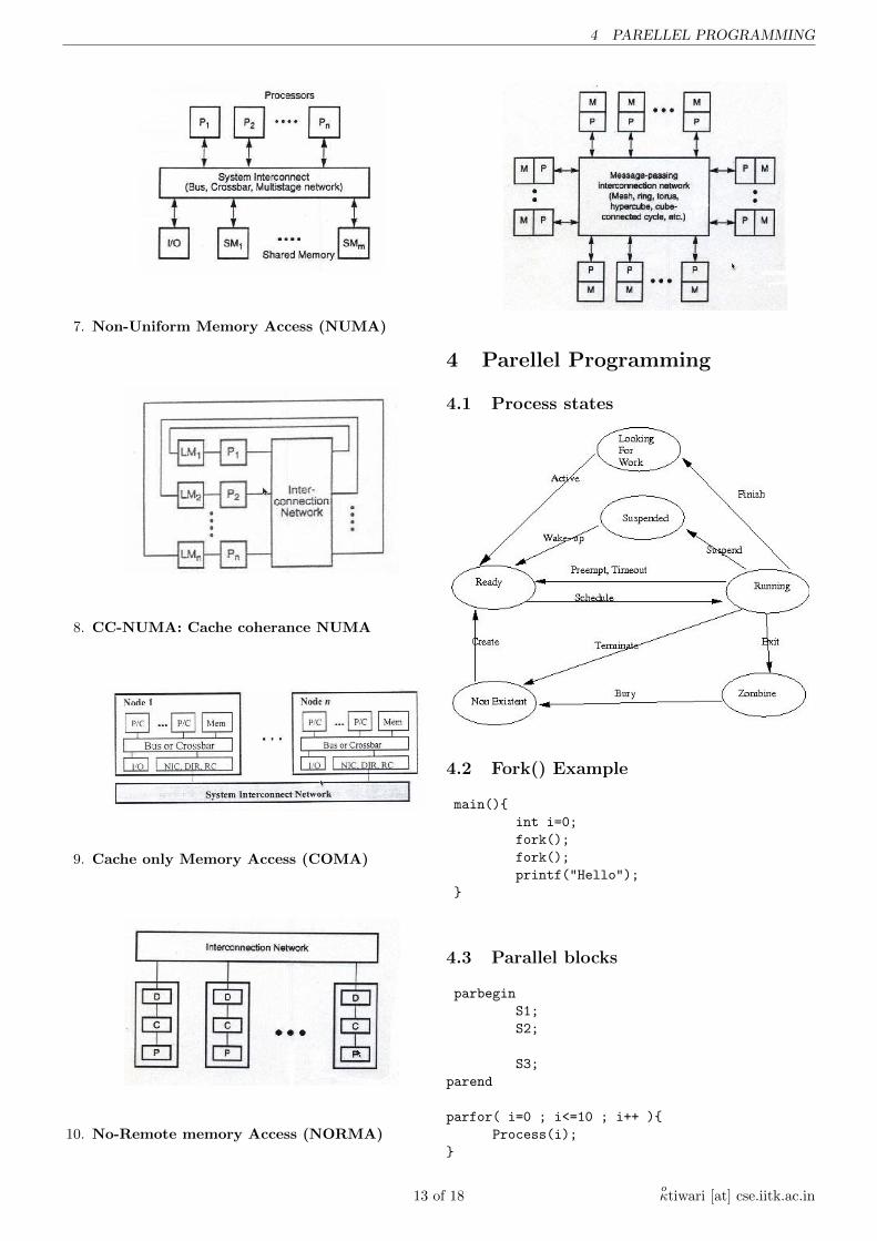
7. Non-Uniform Memory Access (NUMA)
8. CC-NUMA: Cache coherance NUMA
9. Cache only Memory Access (COMA)
10. No-Remote memory Access (NORMA)
4 Parellel Programming
4.1 Process states
4.2 Fork() Example
main(){
int i=0;
fork();
fork();
printf("Hello");
}
4.3 Parallel blocks
parbegin
S1;
S2;
S3;
parend
parfor( i=0 ; i<=10 ; i++ ){
Process(i);
}
13 of 18oκtiwari [at] cse.iitk.ac.in
4.6 Commonly used interaction modes 4 PARELLEL PROGRAMMING
forall( i=1, N){
C[i] = A[i] + B[i];
}
int pid = my_process_id(i);
4.4 Dynamic Parallelism
Uses constructs as fork() and join()
While( C>0 ) begin
fork(f1(C));
C=f2(C);
end
4.5 Intercation/Communication Issues
4.5.1 Communication
Can be done through 1) through shared variables 2)through parameter passing 3) through message passing
4.5.2 Synchronization
Causes processes to wait for one other or allows the waitingproceses to resume.
� Atomicity
parfor(i:=1;i<n;i++){
atomic{
x=x+1;
y=y-1;
}
}
� Control SynchronizationProcess waits until execution reaches certain controlstates.
parfor(i:=1;i<n;i++){
Pi; barrier; Qi;
}
parfor(i:=1;i<n;i++){
critical{
x=x+1;
y=y-1;
}
}
� Data SynchronizationProcess waits until execution reaches certain datastates.
wait(x>1)
parfor(i:=1;i<n;i++){
lock(S);x=x+1;y=y-1;unlock(S);}
4.5.3 Aggregation
To merge partial results generated by component pro-cesses. Can be realized as a sequence of supersteps andcommunication/synchronization.
parfor(i:=1;i<n;i++){
x[i]:=A[i]*B[i];
inner product=aggregate_sum(x[i]);
}
4.6 Commonly used interaction modes
4.6.1 Synchronous
All participants must arrive before the interaction begins.A process can exit the interaction and continue to executethe subsequent operation only when all other processeshave finished the interaction. Basically, a two-barrier syn-chronization. Example: send/receive operations.
4.6.2 Blocking
A process can enter its portion of C as soon as it arrivesand can exit as soon as it finishes irrespective of statusof other processes. Example: Blocking send (completionmeans sending the message not necessarily yet received bydestination.
4.6.3 Non-blocking
A process can enter its portion of C as soon as it arrivesand can exit even before it has finished its portion of C.Example: Non-blocking send (completion means request-ing the sending of the message and not necessarily sendingthe message).
14 of 18oκtiwari [at] cse.iitk.ac.in
5 DISTRIBUTED MEMORY AND LATENCY TOLERANCE
4.7 Interaction Patterns
5 Distributed memory and latencytolerance
5.1 Memory Hierarchy Properties
Three fundamental properties for designing an efficientmemory hierarchy.
� Inclusion M1 ⊂M2 ⊂M3...... ⊂Mn
� Coherence Same information at all levels. Effects atmemory/cache replacement policies.
– Write-through (mainly for on-chip I-cache andD-cache)
– Write-back (Off-chip cache)
� Locality of Reference
1. Temporal locality: favours LRU replacement
2. Spatial locality assists in determining the size ofunit data transfer
3. Sequential locality affects the detrmination ofgrain size for optimal scheduling and also affectsprefetch techniques.
5.2 Memory Capacity Planning
� Hit ratiohi at level i represents the probability of finding in-formation item at level i. h0 = 0, hn = 1.
� Access friquency to Mi
fi = (1− h1)(1− h2)....(1− hi−1)hi
f1 � f2 � f3 � f4 � ....� fn
� Effective Access Time
Teff = Σni=1fi.ti
� Hirarchy OptimizationMinimize Teff subject to following
Ctotal = Σni=1ci.Si < C0
Where Si is size of memory Mi, and ci is per unit costof Mi, and C0 is some value.
15 of 18oκtiwari [at] cse.iitk.ac.in
5.4 Latency Tolerance Techniques 5 DISTRIBUTED MEMORY AND LATENCY TOLERANCE
5.3 Cache Coherence Protocols
5.3.1 Sources of Incoherence
� The write by different processors into their cachedcopies of the same cache line in memory, asyn-schronously.
� Process migration among multiple processors withoutalerting each other.
� I/O operations bypassing the owners of cached copies.
5.3.2 Snoopy Coherency Protocols
Constantly monitor the caching events across the bus be-tween processor and memory modules. Generally imple-mented using snoopy buses and require a broadcast mech-anism. Write-Invalidate and Write-Update protocols.
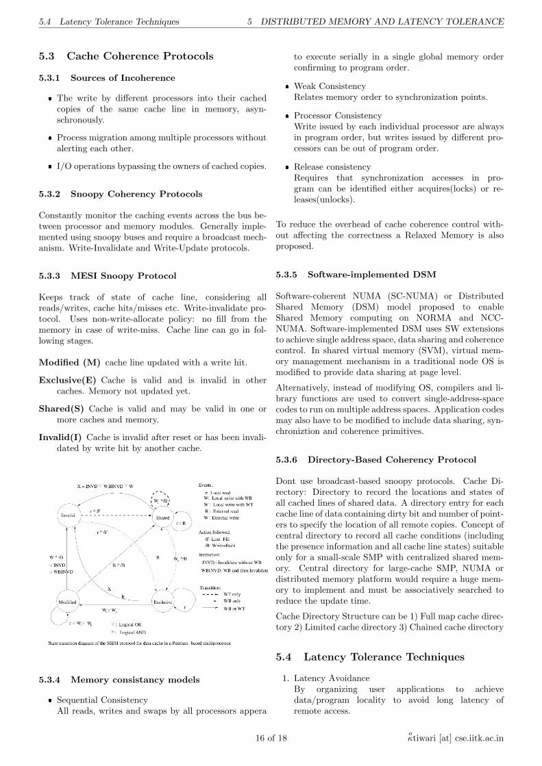
5.3.3 MESI Snoopy Protocol
Keeps track of state of cache line, considering allreads/writes, cache hits/misses etc. Write-invalidate pro-tocol. Uses non-write-allocate policy: no fill from thememory in case of write-miss. Cache line can go in fol-lowing stages.
Modified (M) cache line updated with a write hit.
Exclusive(E) Cache is valid and is invalid in othercaches. Memory not updated yet.
Shared(S) Cache is valid and may be valid in one ormore caches and memory.
Invalid(I) Cache is invalid after reset or has been invali-dated by write hit by another cache.
5.3.4 Memory consistancy models
� Sequential ConsistencyAll reads, writes and swaps by all processors appera
to execute serially in a single global memory orderconfirming to program order.
� Weak ConsistencyRelates memory order to synchronization points.
� Processor ConsistencyWrite issued by each individual processor are alwaysin program order, but writes issued by different pro-cessors can be out of program order.
� Release consistencyRequires that synchronization accesses in pro-gram can be identified either acquires(locks) or re-leases(unlocks).
To reduce the overhead of cache coherence control with-out affecting the correctness a Relaxed Memory is alsoproposed.
5.3.5 Software-implemented DSM
Software-coherent NUMA (SC-NUMA) or DistributedShared Memory (DSM) model proposed to enableShared Memory computing on NORMA and NCC-NUMA. Software-implemented DSM uses SW extensionsto achieve single address space, data sharing and coherencecontrol. In shared virtual memory (SVM), virtual mem-ory management mechanism in a traditional node OS ismodified to provide data sharing at page level.
Alternatively, instead of modifying OS, compilers and li-brary functions are used to convert single-address-spacecodes to run on multiple address spaces. Application codesmay also have to be modified to include data sharing, syn-chroniztion and coherence primitives.
5.3.6 Directory-Based Coherency Protocol
Dont use broadcast-based snoopy protocols. Cache Di-rectory: Directory to record the locations and states ofall cached lines of shared data. A directory entry for eachcache line of data containing dirty bit and number of point-ers to specify the location of all remote copies. Concept ofcentral directory to record all cache conditions (includingthe presence information and all cache line states) suitableonly for a small-scale SMP with centralized shared mem-ory. Central directory for large-cache SMP, NUMA ordistributed memory platform would require a huge mem-ory to implement and must be associatively searched toreduce the update time.
Cache Directory Structure can be 1) Full map cache direc-tory 2) Limited cache directory 3) Chained cache directory
5.4 Latency Tolerance Techniques
1. Latency AvoidanceBy organizing user applications to achievedata/program locality to avoid long latency ofremote access.
16 of 18oκtiwari [at] cse.iitk.ac.in
6.2 Network Performance Metrics or Communication Latency6 SYSTEM INTERCONNECT AND NETWORK TOPOLOGIES
2. Latency ReductionData locality may be limited, Difficult to discoverand change. Latency reduction is achieved by makingcommunication subsystem efficient.
3. Latency HidingPrefetching Techniques, Distributed CoherentCaches, Relaxed Memory Consistency, Multiple-context processors.
5.5 Data Prefetching
Using knowledge about the expected misses in a program.Controlled by SW/HW.
1. Binding PrefetchValue directly loaded into working register duringprefetch. Value may become stale if another proces-sor modifies the location between prefetch and actualreference.
2. Non-binding PrefetchBrings the data to the cache remaining visibleto cache coherence protocol(CCP). HW controlledprefetch includes schemes such as long cache lines (ef-fectiveness limited by reduced spatial locality in mul-tiprocessor applications) and instruction lookahead(effectiveness limited by branches and finite buffersize).
5.6 Context-switching policies
1. Switch on cache missR: Av. interval between misses, L: Recovery time.
2. Switch on every loadR: Av. interval between loads. L1, L2: Latencieswith and without misses. p1, p2: prob. of switchwith or without miss.
3. Switch on every instructionInterleaving of instructions. Supports pipelined exe-cution but cache misses may increase due to breakingof locality. Can hide pipeline dependence.
4. Switch on block of instructionsImproved cache-hit ratio due to preservance of local-ity.
6 System Interconnect and Net-work Topologies
6.1 Switched Networks
Allocate/deallocate media resources to one request at atime. Even shared-media networks can be converted toswitched networks.
1. Circuit switched networksEntire path from source node to destination reservedfor entire period of transmission.
2. Packet switched networksLong messages broken into sequence of smaller pack-ets containing routing information and segment ofdata payload. Packets can be routed separately ondifferent paths. Better utilization of resources butneeds disassembly and reassembly of messages. Dif-ferent messages may have different packet sizes.
3. Cell switched networksPartitioning of long packets into fixed-size small cells.Small packets need not wait for long packets. Con-stant transmission delay is possible. Simplified HWdesign of cell switches because of fixed size. May leadto low network performance if retransmission of lostcells not allowed.
6.2 Network Performance Metrics orCommunication Latency
1. SW Overhead associated with sending and receivingof messages at bot ends of network. Contributed byhost kernels in handling the message.
2. Channel Delay caused by channel occupancy. Deter-mined by bottleneck link or channel.
3. Routing Delay caused by successive switches in mak-ing sequence of routing decisions along the routingpath. Depends on routing distance.
4. Contention Delay caused by traffic contentions in thenetwork. Difficult to predict. Network Latency Sumof Channel Delay and Routing Delay.
Network Latency is sum of Channel Delay and RoutingDelay.
6.3 Routing Schemes and Functions
1. Store-and-Forward RoutingPacket stored in packet buffer in a node before for-warding to outgoing link. Non-overlapped transmis-sion of packets. Header determines the routing pathand then entire packet forwarded to next node.
2. Cut-Through or Wormhole RoutingEach node uses a flit buffer to hold one flit or cell ofthe packet which is automatically forwarded throughan out-link to next node once the header is decoded.Rest of the data flits of the packet follow the samepath in a pipelined fashion reducing the transmissiontime significantly.
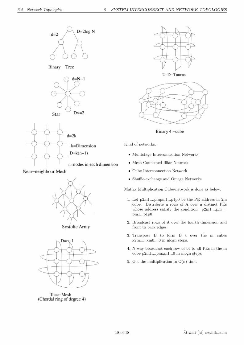
6.4 Network Topologies
Binary Tree, star, near neibour mesh, systolic array, illiacmesh, 2-D tauras, cube, binary 4-cube.
17 of 18oκtiwari [at] cse.iitk.ac.in
6.4 Network Topologies 6 SYSTEM INTERCONNECT AND NETWORK TOPOLOGIES
Kind of networks.
� Multistage Interconnection Networks
� Mesh Connected Illiac Network
� Cube Interconnection Network
� Shuffle-exchange and Omega Networks
Matrix Multiplication Cube-network is done as below.
1. Let p2m1....pmpm1...p1p0 be the PE address in 2mcube. Distribute n rows of A over n distinct PEswhose address satisfy the condition: p2m1....pm =pm1...p1p0
2. Broadcast rows of A over the fourth dimension andfront to back edges.
3. Transpose B to form B t over the m cubesx2m1....xm0....0 in nlogn steps.
4. N way broadcast each row of bt to all PEs in the mcube p2m1....pmxm1...0 in nlogn steps.
5. Get the multiplication in O(n) time.
18 of 18oκtiwari [at] cse.iitk.ac.in