Embed Size (px)
Citation preview
Installation GuideConnect180GXGGParadigm

- 2 -
GXGGParadigm
The information in this document has been carefully compiled and checked for technical accuracy. Paradigm Communication Systems Ltd. accept no liability for inaccuracies or errors. In line with the company policy of technical advancement, the information within this document may be changed. The user should ensure that the correct issue of the document is used.Paradigm assumes no responsibility for the use of this document if any unauthorised changes to the content or format are made.This document is provided without implied or expressed warranty of any kind, including but not limited to the implied warranties of merchantability and fitness for purpose.
Other manufacturers’ registered trademarks and trade names which appear in this document are hereby acknowledged.
Comments or correspondence regarding this document should be addressed to:
Paradigm Communication Systems LimitedParadigm House14 Wilsom RoadAlton, HampshireGU34 2PPEnglandTel: +44 (0) 1420 88199Fax: +44 (0) 1420 88842Email: [email protected]
© Paradigm Communication Systems Limited 2014. All rights reserved.No part of this document may be reproduced in any form without the prior written consent of Paradigm Communication Systems Limited. Use of the information contained herein is strictly reserved for Paradigm Communication Systems Limited. Other use in any form and/or by any means whatsoever is strictly prohibited.
DN: ED-IMA-02398 Rev: 05 Release Date: 17/07/2015
Legal
Safe UseWARNING
Radiation Hazard. Transmitter power levels are sufficient to cause blindness or other serious injury to body tissue. Do not power on the PIM and Transceiver until it is safe to do so.
The equipment described in this manual is intended to be installed, used and operated only for the purpose for which it was designed, in accordance with the safety procedures and any other instructions given in this manual. Nothing stated in this manual reduces the professional responsibilities of users for the exercise of sound judgement and best practice.
WARNING
Risk of Electric Shock. High voltages exist within the units and the cables providing power to the units. Always remove power from these devices when performing maintenance. Do not modify power cables or physical unit in any way.
WARNING
This equipment is intended for installation in a restricted access location. The equipment should not be touched during operation.
- 3 -
Installation GuideConnect180
Contents Safe Use ............................................................................................................2Legal ..................................................................................................................2Contents ............................................................................................................3Site Survey for Antenna Installation ...............................................................4Installation Process..........................................................................................4System Packaging Content .............................................................................5Recommended Tools for Installation ..............................................................5Antenna Installation .........................................................................................6
Az/El Mount Installation ..................................................................................6Attach the Az/El mount ......................................................................................................7
Attach antenna rear bracket ...........................................................................8Attach Elevation adjuster ...............................................................................9Antenna mounting ........................................................................................10Reflector assembly .......................................................................................11Boom arm assembly ....................................................................................11Boom Arm Supports .....................................................................................12
Transceiver Mounting ....................................................................................14RF Circuit Setup .............................................................................................15Antenna Pointing ............................................................................................16
Elevation - Initial Setting ...............................................................................16Measurement of Elevation Angle .................................................................16Azimuth - Initial Setting ................................................................................16Elevation Fine Pointing ................................................................................17Torque and Sequence ..................................................................................17
Antenna Grounding ........................................................................................19Elevation Calculation Chart ...........................................................................20Azimuth Calculation Chart .............................................................................21Transceiver Control LEDs..............................................................................22
Transceiver Port Identification ......................................................................22Periodic Maintenance.....................................................................................23

- 4 -
GXGGParadigm
Installation Process
Investigate the intended installation site for the satellite antenna, and using the azimuth and elevation angles provided by the PIM (see PIM Operators Manual), confirm there are no line-of-sight obstructions. Remove any obstructions if possible, or select a new location with a clear line-of-sight to the satellite.
Site Survey for Antenna Installation
1. Install the Antenna mount• Non-Penetrating
Roof Mount• Kingpost• ISO Container Mount
2. Assemble and Install the Antenna
4. Point the Antenna• Coarse Pointing• Fine Pointing
5. Commission the installation
page 6
page 16
3. Assemble RF Circuit• Transceiver• PIM (Indoor PIM or
Rack Mount PIM option)
Refer to the ParadigmGX Antenna Mount Installation Manual
- 5 -
Installation GuideConnect180
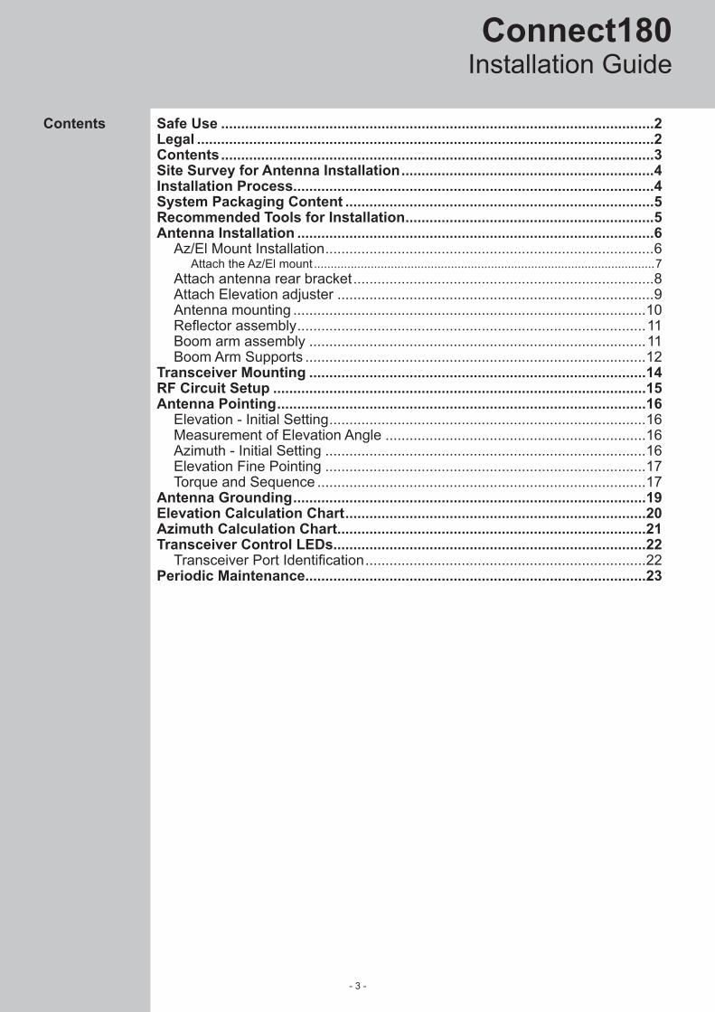
Package Contents:
1. 180cm 1-piece GRP antenna2. Az/El mount3. Elevation Adjustment Rod4. Antenna Rear Bracket5. Boom Arm Supports6. Boom Arm7. 5W Ka-Band transceiver with integrated feed8. Transceiver Mounting Bracket9. IFL Cable (M&C, Tx, Rx), optional Paradigm-GPS10. PIM (Outdoor, Indoor, or Rack Mount)11. Assembly nuts, bolts and washers
a. Feed Support mounting nuts/bolts pack (7580779)b. Az/El Mount and Antenna Rear Bracket mounting nuts/bolts pack (7580781)c. Reflector mounting nuts/bolts pack (7580777)
1
2
3
4
System Packaging Content
5
67
8
Compass & InclinometerSpirit level10, 13, 17, 19, 30 and 36mm sockets / ring spanners3, 4 and 5mm hex keysTorque wrenchSpectrum AnalyserPortable Computer to complete the pointing process
Recommended Tools for Installation
- 6 -
GXGGParadigm
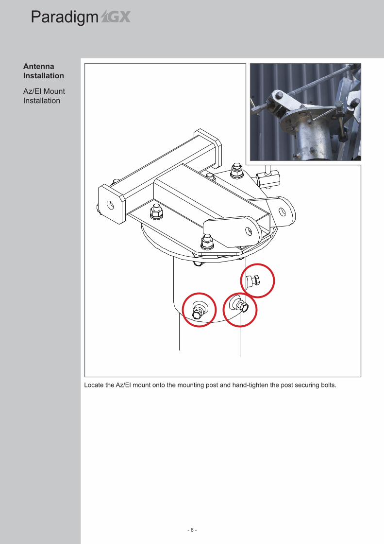
Antenna Installation
Locate the Az/El mount onto the mounting post and hand-tighten the post securing bolts.
Az/El Mount Installation
- 7 -
Installation GuideConnect180
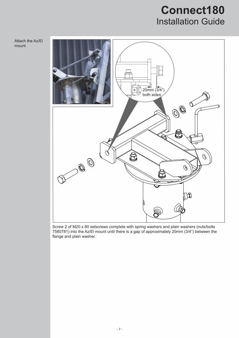
Attach the Az/El mount
Screw 2 of M20 x 80 setscrews complete with spring washers and plain washers (nuts/bolts 7580781) into the Az/El mount until there is a gap of approximately 20mm (3/4”) between the flange and plain washer.
20mm (3/4”) both sides

- 8 -
GXGGParadigm
Attach antenna rear bracket
Hang the antenna rear bracket on the Az/El mount and tighten the M20 setscrews to 20ftlb (27Nm).

- 9 -
Installation GuideConnect180
Attach Elevation adjuster
Assemble the elevation adjuster assembly using 4 of M20 x 45 setscrews complete with spring washers and plain washers (nuts/bolts 7580781). Torque the setscrews to 20lbft (27Nm).
NOTE: To ensure maximum fine tuning adjustment in both directions, check that the top of the elevation adjustment rod is aligned with the top of the indicator bar.

- 10 -
GXGGParadigm
Antenna mounting
Assemble 4 of M12 x 130 coach bolts and captive nuts (nuts/bolts kit 7580777) to the rear face of the reflector and torque to 20ftlb (27Nm). Screw the clamp nuts onto each coach bolt until there is a gap of 12mm (1/2”).
12mm (1/2”)
Clamp Nut
Captive Nut
Assemble the reflector support bracket onto the reflector using 3 of M6 x 25 setscrews, spring washers and plain washer (nuts/bolts kit 7580779). Torque the setscrews to 8lbft (12Nm).
- 11 -
Installation GuideConnect180
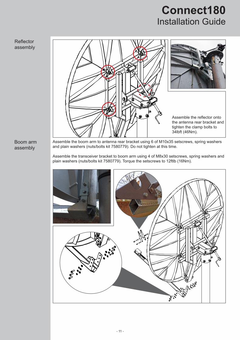
Boom arm assembly
Reflector assembly
Assemble the reflector onto the antenna rear bracket and tighten the clamp bolts to 34lbft (46Nm).
Assemble the boom arm to antenna rear bracket using 6 of M10x35 setscrews, spring washers and plain washers (nuts/bolts kit 7580779). Do not tighten at this time.
Assemble the transceiver bracket to boom arm using 4 of M8x30 setscrews, spring washers and plain washers (nuts/bolts kit 7580779). Torque the setscrews to 12ftlb (16Nm).

- 12 -
GXGGParadigm
Assemble the boom arm supports using 4 of M6 x 25 setscrews, spring washers, plain washers and nuts (nuts/bolts kit 7580777). Do not tighten at this time
Boom Arm Supports
- 13 -
Installation GuideConnect180
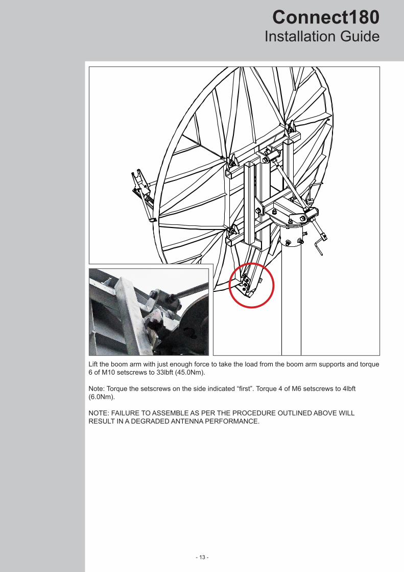
Lift the boom arm with just enough force to take the load from the boom arm supports and torque 6 of M10 setscrews to 33lbft (45.0Nm).
Note: Torque the setscrews on the side indicated “first”. Torque 4 of M6 setscrews to 4lbft (6.0Nm).
NOTE: FAILURE TO ASSEMBLE AS PER THE PROCEDURE OUTLINED ABOVE WILL RESULT IN A DEGRADED ANTENNA PERFORMANCE.

- 14 -
GXGGParadigm
Transceiver Mounting
Mount the transceiver on the transceiver mounting bracket using the supplied hex bolts. Fit the upper two bolts to the transceiver before fitting, and slide the transceiver onto the mounting bracket. Fit the lower two bolts, and tighten all bolts to hold the transceiver in place.
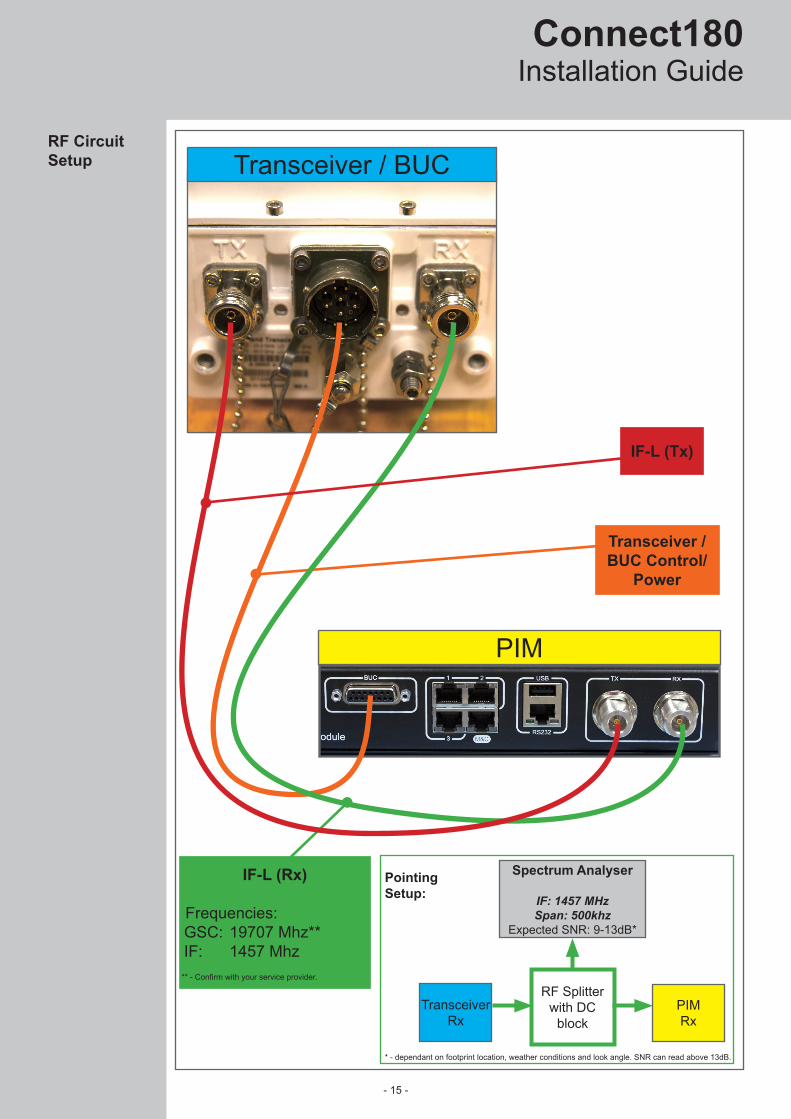
Connect the IF-L cables from the transceiver to the PIM. Connect the Power/Control cable from the transceiver to the PIM, and power on the PIM. Confirm the transceiver has powered on.
- 15 -
Installation GuideConnect180
PointingSetup:
IF-L (Tx)
Transceiver / BUC Control/
Power
RF Circuit Setup Transceiver / BUC
PIM
IF-L (Rx)
Frequencies:GSC: 19707 Mhz**IF: 1457 Mhz
RF Splitter with DC
block
Spectrum Analyser
IF: 1457 MHzSpan: 500khz
Expected SNR: 9-13dB*
Transceiver Rx
PIMRx
* - dependant on footprint location, weather conditions and look angle. SNR can read above 13dB.
** - Confirm with your service provider.

- 16 -
GXGGParadigm
Antenna Pointing
Elevation - Initial Setting
Alignment with the satellite is obtained by setting elevation and azimuth. Charts are provided on page 20 and page 21 to determine the elevation and azimuth values for your earth station antenna site. “ΔL” is the difference between the earth station antenna site longitude and the satellite longitude. Use “ΔL” and your earth station latitude to obtain elevation and azimuth setting.
Use the chart on page 20 to determine your elevation setting.With NUT 'A' tightened, adjust NUTS 'B' until desired course elevation position is desired. For quick adjustment, take the weight of the antenna on the boom arm whilst adjusting the position of NUTS ‘B’ by hand.
Note: this is an approximate setting, the optimum setting will be achieved during fine tuning.
To measure coarse elevation angle place an inclinometer on Face 'E'.
Note: when face 'E' is vertical (90°) the antenna is pointing to 22.6°.
Refer to the azimuth value determined on page 21. Values in the chart must be adjusted for magnetic deviation for your location for correct compass reading. Partially tighten bolts ‘C’ (enough to align the Az/El mount to the pipe and allow azimuth rotation). Rotate the reflector and mount on the pipe, pointing it to the compass reading for your location and satellite.With a spectrum analyser connected to the Rx port of the transceiver, and the transceiver powered on, sweep the antenna in azimuth for signal. If the desired signal is not located then increase or decrease elevation setting and repeat the azimuth sweep. When the desired signal has been found, tighten progressively (1/8 turn each) the 6 pipe clamp BOLTS 'C' until torqued to 30lbft (40Nm).
NUT ‘A’
NUTS ‘B’
FACE ‘E’
Measurement of Elevation Angle
Azimuth - Initial Setting
BOLTS ‘C’

- 17 -
Installation GuideConnect180
Lock NUTS 'B' to the lower block. Unscrew NUT 'A' back to the end of the fine thread. The fine elevation adjustment is performed by rotating the elevation fine adjust handle. Loosen NUTS ‘D’, and turn the azimuth fine adjust handle to perform fine adjustment of the azimuth.
Using a spectrum analyser, obtain the most accurate alignment and maximum antenna performance. Alternate between elevation and azimuth fine tuning handles to reach maximum strength, until no improvement can be detected. Tighten NUT ‘A’ and NUTS ‘D’ once pointing is complete.
Once the antenna pointing is complete, torque the hardware in the sequence as follows:1. Torque azimuth NUTS 'D' to 90lbft (70Nm).2. Torque pivot setscrews 'E' to 180lbft (240Nm)3. Torque upper elevation setscrews 'F' to 180lbft (240Nm)4. Torque lower elevation setscrews 'G' to 180lbft (240Nm)5. Tighten fine elevation NUT 'A' onto upper elevation block.
Elevation Fine Pointing
NUTS ‘D’
Elevation Fine Adjust Handle
Azimuth Fine Adjust Handle
Torque and Sequence
Setscrews ‘F’
Setscrews ‘E’
Setscrews ‘G’
- 18 -
GXGGParadigm
311
12.2
22.6
°
1429
56.3
2474
97.4
54221.4
RF
FH
TM
MO
FV
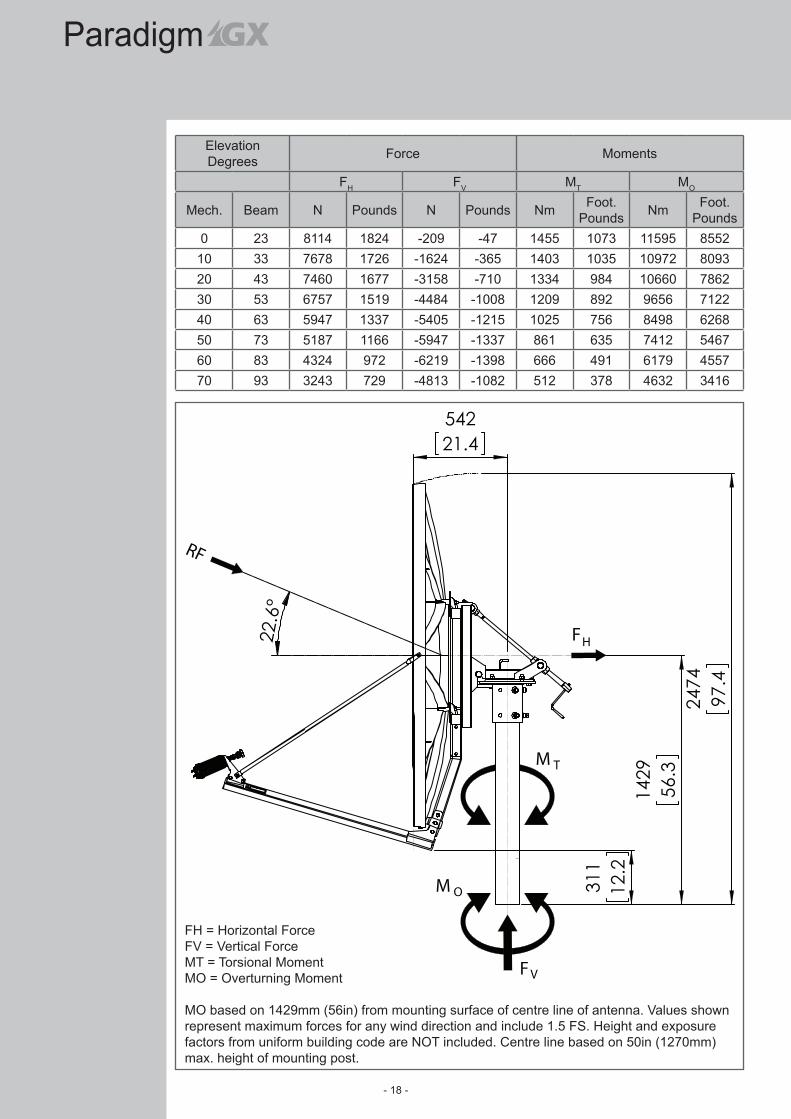
Elevation Degrees Force Moments
FH FV MT MO
Mech. Beam N Pounds N Pounds Nm Foot.Pounds Nm Foot.
Pounds0 23 8114 1824 -209 -47 1455 1073 11595 8552
10 33 7678 1726 -1624 -365 1403 1035 10972 809320 43 7460 1677 -3158 -710 1334 984 10660 786230 53 6757 1519 -4484 -1008 1209 892 9656 712240 63 5947 1337 -5405 -1215 1025 756 8498 626850 73 5187 1166 -5947 -1337 861 635 7412 546760 83 4324 972 -6219 -1398 666 491 6179 455770 93 3243 729 -4813 -1082 512 378 4632 3416
FH = Horizontal ForceFV = Vertical ForceMT = Torsional MomentMO = Overturning Moment
MO based on 1429mm (56in) from mounting surface of centre line of antenna. Values shown represent maximum forces for any wind direction and include 1.5 FS. Height and exposure factors from uniform building code are NOT included. Centre line based on 50in (1270mm) max. height of mounting post.
- 19 -
Installation GuideConnect180
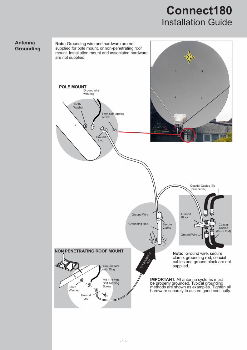
NON PENETRATING ROOF MOUNT
Ground wirewith ring
Ground Lug
5mm self-tapping screw
ToothWasher
M6 x 16 mmSelf Tapping Screw
Ground Lug
Ground Wirewith Ring
ToothWasher
Note: Grounding wire and hardware are not supplied for pole mount, or non-penetrating roof mount. Installation mount and associated hardware are not supplied.
Ground Wire
SecureClamp
Grounding Rod
Ground Wire
Ground Block
Coaxial Cables (To Transceiver)
Coaxial Cables
(From PIM)
Note: Ground wire, secure clamp, grounding rod, coaxial cables and ground block are not supplied.
IMPORTANT: All antenna systems must be properly grounded. Typical grounding methods are shown as examples. Tighten all hardware securely to assure good continuity.
TO G
ROUN
DING
RO
D
Antenna Grounding
POLE MOUNT

- 20 -
GXGGParadigm
To calculate the elevation that would incorporate the skew angle of the satellite terminal:1. Confirm the correct curve for the longitude delta (Δ) calculated for the Skew Calculation. 2. Find latitude on the horizontal axis.3. Find where the curve for the calculated delta intersects the latitude value.4. Read off the vertical axis for the elevation angle. Example: Earth station location: 001° 02’ 49” W 51° 09’ 02” N (51.151°, -001.047°) Satellite Location: 62.6° E Longitude Delta: (-001.047 - 62.6) = -63.65° Elevation angle: 7.7°
Elevation Calculation Chart
Earth station latitude in degrees, north or south of the equator.
Ele
vatio
n
- 21 -
Installation GuideConnect180
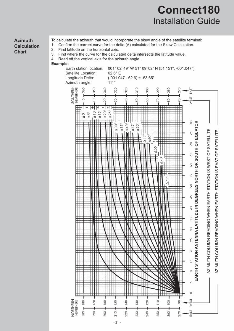
Azimuth Calculation Chart
To calculate the azimuth that would incorporate the skew angle of the satellite terminal:1. Confirm the correct curve for the delta (Δ) calculated for the Skew Calculation.2. Find latitude on the horizontal axis.3. Find where the curve for the calculated delta intersects the latitude value.4. Read off the vertical axis for the azimuth angle. Example: Earth station location: 001° 02’ 49” W 51° 09’ 02” N (51.151°, -001.047°) Satellite Location: 62.6° E Longitude Delta: (-001.047 - 62.6) = -63.65° Azimuth angle: 111°
AZI
MU
TH C
OLU
MN
RE
AD
ING
WH
EN
EA
RTH
STA
TIO
N IS
WE
ST
OF
SAT
ELL
ITE
AZI
MU
TH C
OLU
MN
RE
AD
ING
WH
EN
EA
RTH
STA
TIO
N IS
EA
ST
OF
SAT
ELL
ITE
EAR
TH S
TATI
ON
AN
TEN
NA
LATI
TUD
E IN
DEG
REE
S N
OR
TH O
R S
OU
TH O
F EQ
UAT
OR
- 22 -
GXGGParadigm
1 432
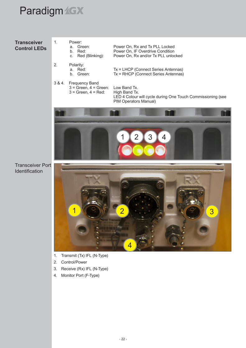
Transceiver Control LEDs
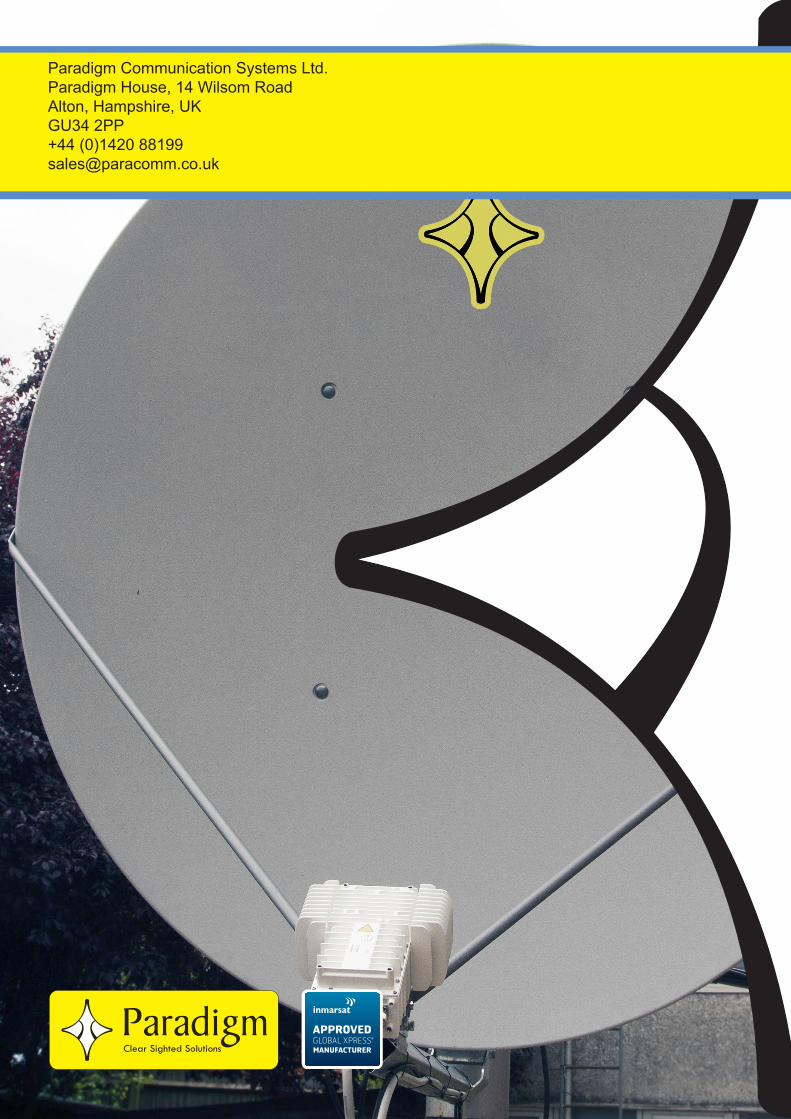
1. Transmit (Tx) IFL (N-Type)2. Control/Power3. Receive (Rx) IFL (N-Type)4. Monitor Port (F-Type)
1
4
32
Transceiver Port Identification
1. Power:a. Green: Power On, Rx and Tx PLL Lockedb. Red: Power On, IF Overdrive Conditionc. Red (Blinking): Power On, Rx and/or Tx PLL unlocked
2. Polarity:a. Red: Tx = LHCP (Connect Series Antennas)b. Green: Tx = RHCP (Connect Series Antennas)
3 & 4. Frequency Band 3 = Green, 4 = Green: Low Band Tx. 3 = Green, 4 = Red: High Band Tx. LED 4 Colour will cycle during One Touch Commissioning (see
PIM Operators Manual)

- 23 -
Installation GuideConnect180
To ensure peak performance of the antenna system and to maintain validity of the warranty, the user should perform a periodic inspection every 6 months or following any severe weather event. As a minimum the following items should be inspected.
1. INSTALLATION MOUNT• Check for loose hardware - tighten if necessary.• Check integrity of anchor bolts or hardware securing mount to the building or
foundations.• Check ballast of Non-Penetrating Roof Mounts - cracked or broken blocks must be
replaced.• Check hardware and structural members for signs of corrosion - repair or replace as
needed.
2. ANTENNA BACK STRUCTURE OR AZ/EL MOUNT• Check for loose hardware - tighten if necessary.• Check for signs of structural damage such as bending or cracking.• Check hardware and structural members for signs of corrosion - repair or replace as
needed.
3. REFLECTOR• Check integrity of bolts securing reflector to back structure or Az/El mount. Tighten any
loose hardware.• Check for signs of damage such as cracking. Inspect reflector face for impact damage.• Check hardware for signs of corrosion - repair or replace as needed.
4. FEED SUPPORT STRUCTURE• Check for loose hardware - tighten if necessary.• Check for signs of structural damage such as bending.• Check hardware and structural members for signs of corrosion - repair or replace as
needed.
5. FEED & RF COMPONENTS• Check for loose hardware - tighten if necessary.• Check hardware for signs of corrosion - repair or replace as needed.• Check feed lens or window for damage or signs of leaking.• Check waveguide flange connections between feed and RF electronics.
6. ELECTRICAL• Check for loose cables and connectors - tighten if necessary.• Check for tight grounding connections.• Check cables for weathering or cracks.
Periodic Maintenance
Paradigm Communication Systems Ltd.Paradigm House, 14 Wilsom RoadAlton, Hampshire, UKGU34 2PP+44 (0)1420 [email protected]