Embed Size (px)
Citation preview


In the name of the ALLAH , the most beneficent , the most merciful
Design of parabolic trough solar collectors power plant with storage
system
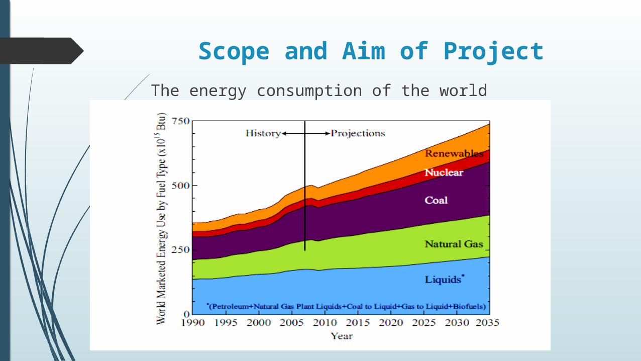
Scope and Aim of ProjectThe energy consumption of the world
Aim of project
The main purpose of this project is to design of a
parabolic trough solar thermal power plant with
capacity of 100MW and evaluate its performance at
different weather conditions
Advantages of the renewable energy
Rising fossil fuel prices Energy security
Greenhouse gas emissions
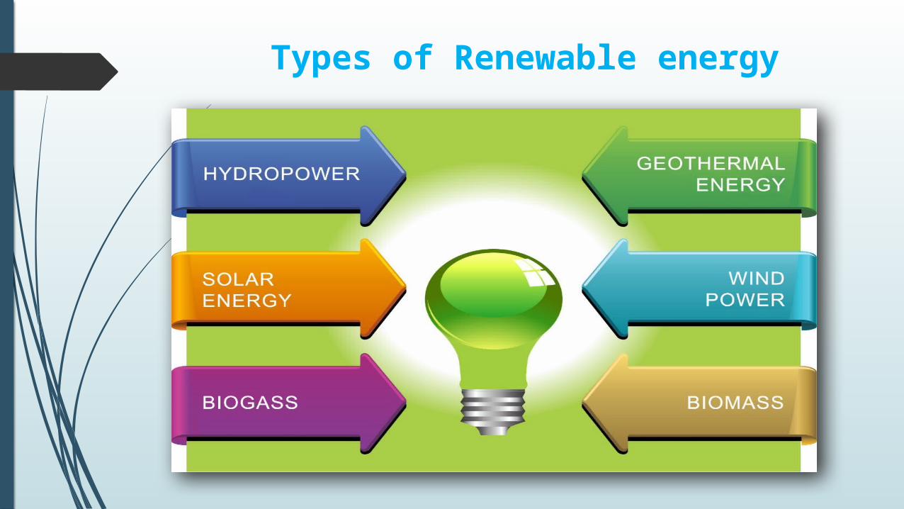
Types of Renewable energy

Concept of concentrating solar power (CSP) plant

Solar Thermal Power Plant Technologies
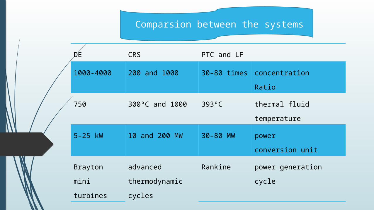
DE CRS PTC and LF
1000-4000 200 and 1000 30–80 times concentrationRatio
750 300ºC and 1000 393ºC thermal fluid temperature
5–25 kW 10 and 200 MW 30–80 MW powerconversion unit
Brayton mini turbines
advanced thermodynamic cycles
Rankine power generation cycle
Comparsion between the systems
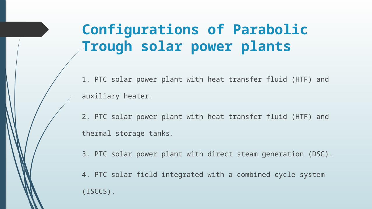
Configurations of Parabolic Trough solar power plants
1. PTC solar power plant with heat transfer fluid (HTF) and auxiliary heater.
2. PTC solar power plant with heat transfer fluid (HTF) and thermal storage tanks.
3. PTC solar power plant with direct steam generation (DSG).
4. PTC solar field integrated with a combined cycle system (ISCCS).

PTC Solar Power Plant with Heat Transfer Fluid (HTF) auxiliary heater.

PTC Solar Power Plant with HTF and Thermal Storage Tanks

PTC Solar Power Plant with Direct Steam Generation (DSG)
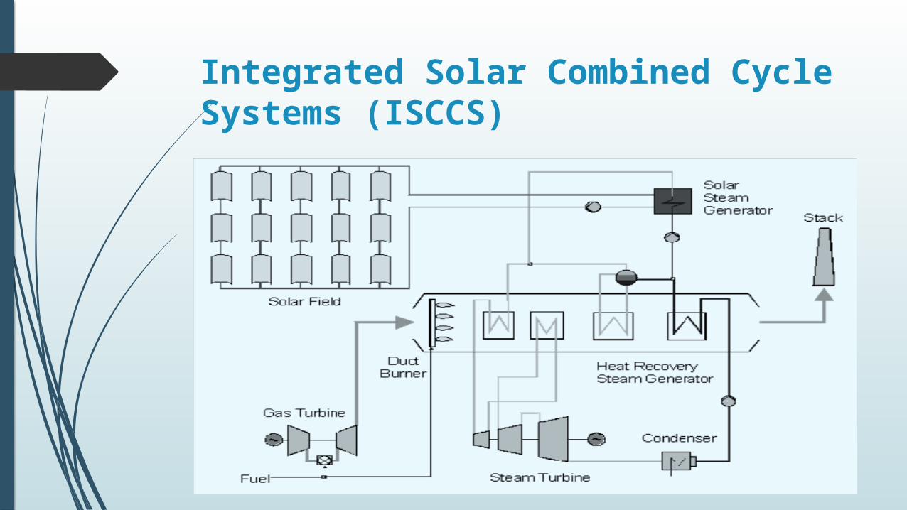
Integrated Solar Combined Cycle Systems (ISCCS)

Operational Solar Thermal Power Stations
MW Name Location Technology
200 Andasol 4–7 Granada parabolic trough with heat storage
100Solnova 2, 4–5
Sevilla parabolic trough with heat storage
50 Ibersol Badajoz Fuente de Cantos parabolic trough
50 Ibersol Valdecaballeros 1–2 Valdecaballeros parabolic trough
50 Ibersol Sevilla Aznalcollar parabolic trough
50 Ibersol Almería Tabernas parabolic trough
50 Ibersol Albacete Almansa parabolic trough
50 Ibersol Murcia Lorca parabolic trough
50 Ibersol Zamora Cubillos parabolic trough

Component of the system
Solar fieldStorage system Power block

Solar
fieldReceiver
Parabolic
trough
Heat transfer
fluid

Solar field
Solar field orientation
Solar field layout
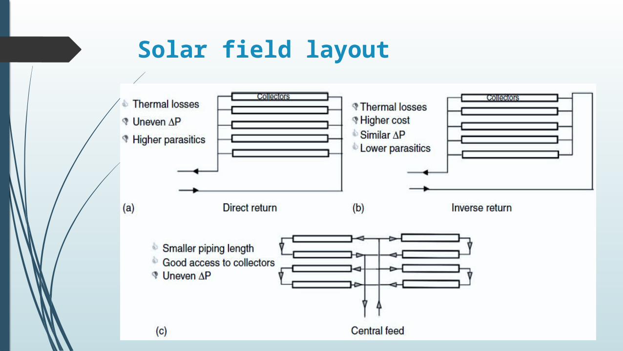
Solar field layout

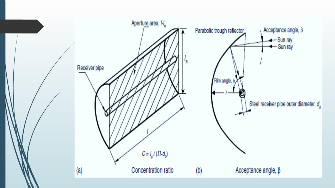
Parabolic Trough Collector (PTC)1. Design Parameters of a (PTC)→concentration ratio
→ The acceptance angle
→The rim angle

Mirror material

Bearing structure

Receiverhigh radiation absorption low heat losses
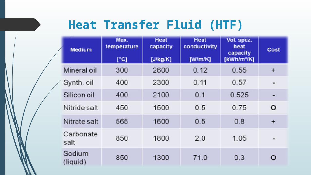
Heat Transfer Fluid (HTF)
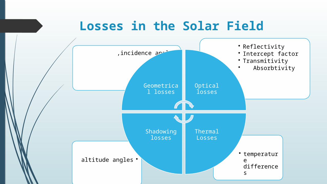
Losses in the Solar Field
• temperature differences
•altitude angles
• Reflectivity• Intercept factor• Transmitivity • Absorbtivity
•incidence angle,
Geometrical losses
Optical losses
Thermal Losses
Shadowing losses
Heat storage system
One challenge facing the widespread use of solar energy
is reduced or curtailed energy production when the sun
sets or is blocked by clouds. Thermal energy storage
provides a workable solution to this challenge

Storage systems Technologies
The two-tank direct system
Two-tank indirect system
Single-tank thermocline system
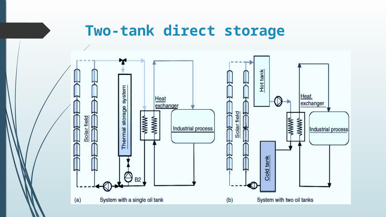
Two-tank direct storage
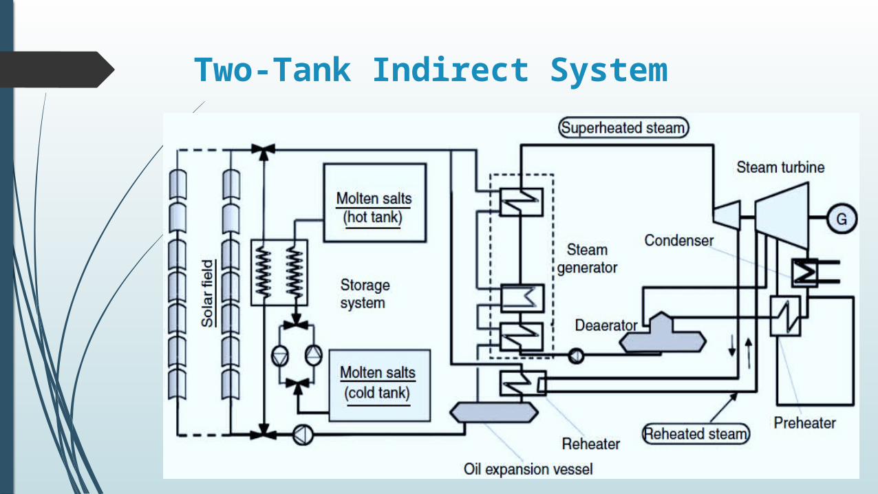
Two-Tank Indirect System

Single-Tank Thermocline System
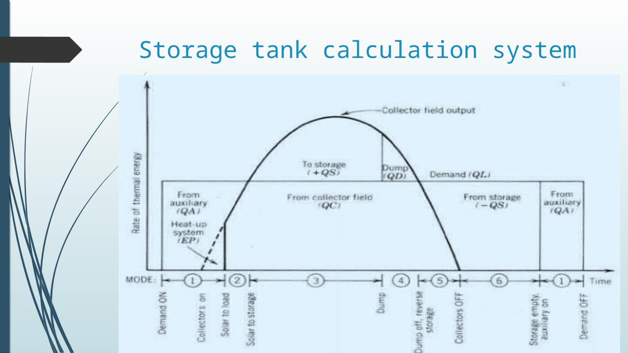
Storage tank calculation system
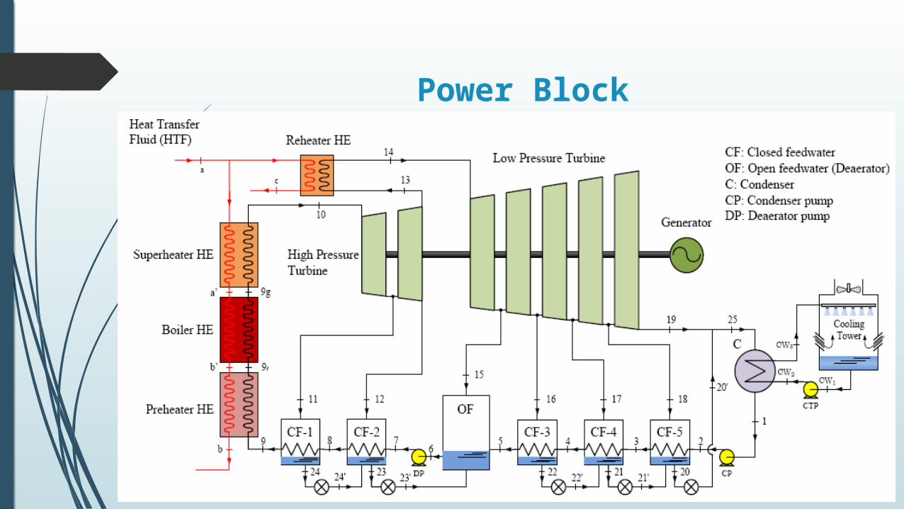
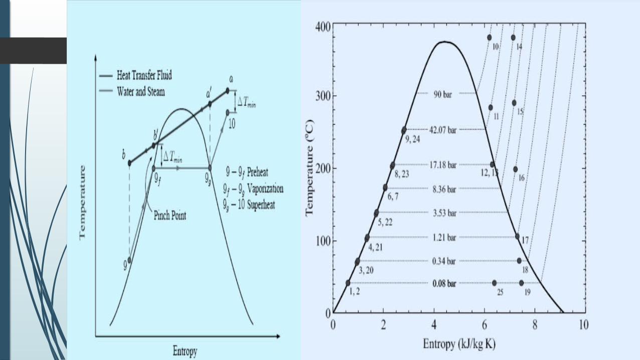
Power Block
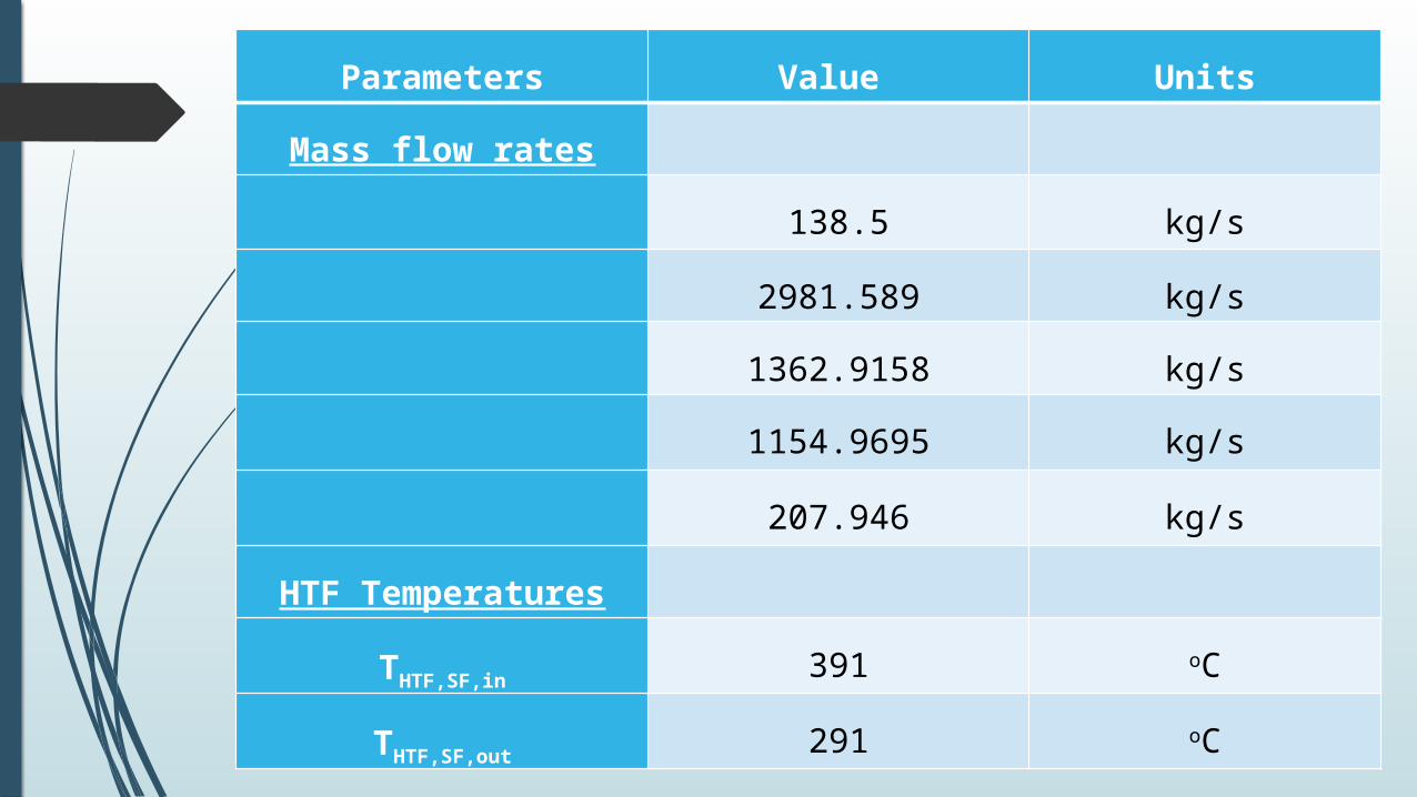
Parameters Value Units
Mass flow rates 138.5 kg/s
2981.589 kg/s
1362.9158 kg/s
1154.9695 kg/s
207.946 kg/s
HTF Temperatures THTF,SF,in 391 oC
THTF,SF,out 291 oC

Heat transfer rates313470.637 kW
265643 kW
39749.5 kW
190991.5 kW
34902 kW
125226 kW

Power43832.88 kW
68475.8958 kW
112308.7758 kW
100000.00 kW
98400.00 kW
92.752 kW
1400.235 kW
Efficiency38.75%

�̇�𝑃𝐵=�̇�𝐻𝑇𝐹=�̇�𝑆𝐺+�̇�𝑟𝑒h𝑒𝑎𝑡𝑒𝑟+
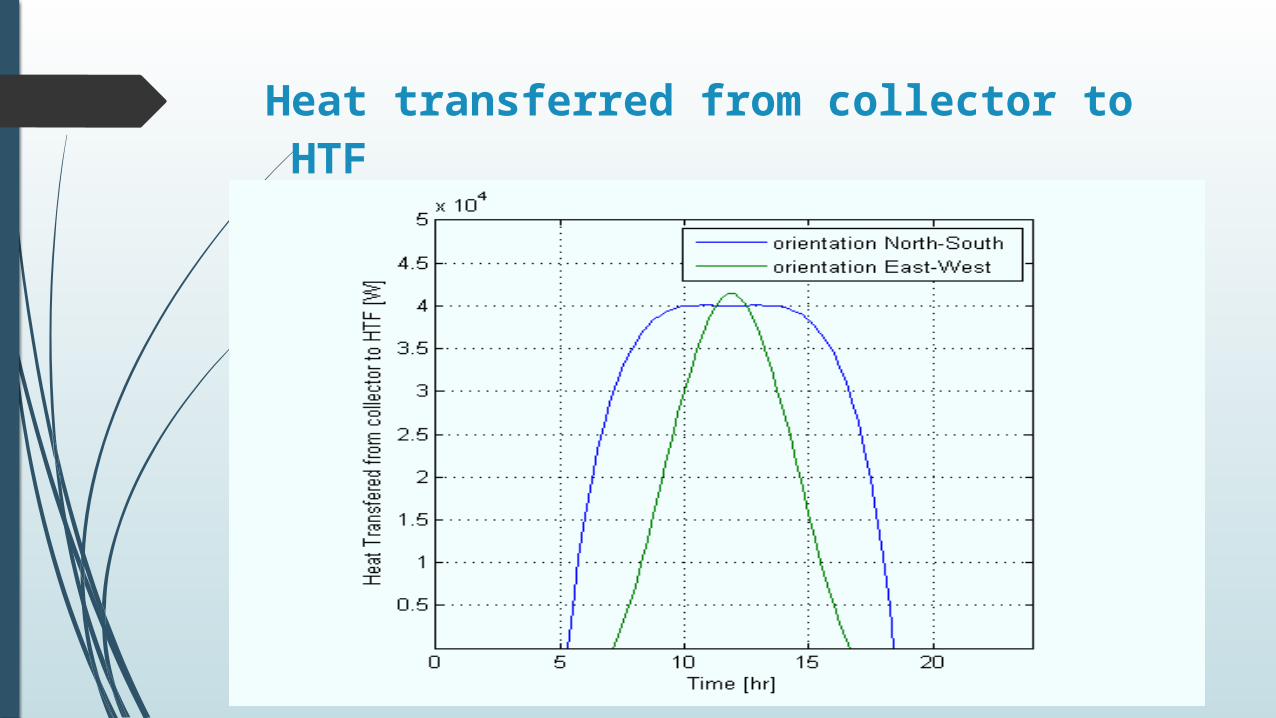
Heat transferred from collector to HTF
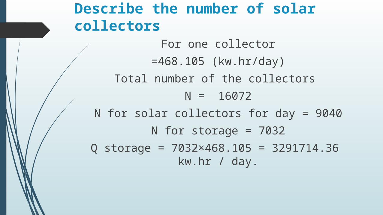
Describe the number of solar collectors
For one collector=468.105 (kw.hr/day)
Total number of the collectors N = 16072
N for solar collectors for day = 9040N for storage = 7032
Q storage = 7032×468.105 = 3291714.36 kw.hr / day.
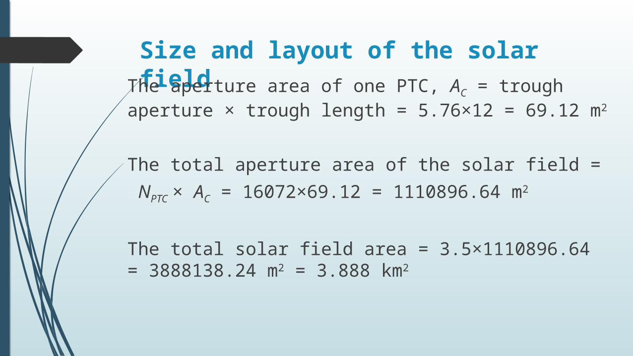
Size and layout of the solar fieldThe aperture area of one PTC, AC = trough aperture × trough length = 5.76×12 = 69.12 m2
The total aperture area of the solar field = NPTC × AC = 16072×69.12 = 1110896.64 m2
The total solar field area = 3.5×1110896.64 = 3888138.24 m2 = 3.888 km2

Praise be to Allah, the Lord of the Worlds
Thank you