Embed Size (px)
Citation preview
Paper VI
Off-Line Programming or Robots for MetalDeposition
Mikael Ericsson, Per Nylén, Fredrik Danielsson, HenrikJohansson
Presented 7th International Conference on Trends in WeldingResearch, Pine Mountain, Georgia, USA, May 16-20, 2005


Off-Line Programming or Robots for MetalDeposition
Mikael Ericsson, Per Nylén, Fredrik Danielsson, Henrik Johansson
Abstract
Metal Deposition (MD) is a rapid prototyping technique to build parts by deposit-ing metal in a required fashion. When a complex-shaped part is to be built, a sim-ulation tool is needed to define robot trajectories. Three different simulation-basedmethods for robot trajectory generation are introduced and compared in this study.The methods are; reversed milling, adapted rapid prototyping and application pro-gramming in a computer aided robotics software. All methods were shown capableof creating robot paths for complex shapes, with the CAR software approach beingthe most flexible. Using this method, the geometry to be built is automatically slicedinto layers and a robot path is automatically generated. The method was tentativelyevaluated and appears to provide a powerful technique in the design and optimisationof robot paths for MD. Experiments showed that it is possible to manufacture fullydense parts using an Nd-Yag laser.
1 Introduction
Many of the complex-shaped components, especially those used in the aerospace and au-tomobile industries, are manufactured by casting or forging. Components made by theseprocesses require extensive machining and finishing operations before they can actuallybe used. If the production volume is low then the production cost for each componentis likely to be rather high. Manufacturing by moulding is also a rather inflexible methodsince it is necessary to change the complete mould in order to effect a change in com-ponent geometry. The development of alternative manufacturing methods is therefore ofsignificant interest.
One interesting alternative is metal Rapid Prototyping (RP) often referred to as MetalDeposition (MD). MD has the potential to be used to manufacture a new part, to addfeatures to an existing part, or to repair worn parts. The technique uses a welding heatsource to melt a powder or a wire material which solidifies on a surface, thus enablinga part to be built drop-by-drop. An example of such a method is the Laser-EngineeredNet Shaping (LENS) process developed at Sandia National Laboratories and StanfordUniversity [1]. In the LENS system a laser beam melts the top layer of the part in areaswhere material is to be added. Materials that can be used include 316 stainless steel,Inconel 625, tungsten, and titanium carbide cermets The LENS process produces fully-dense parts with functional mechanical properties. However, at present, the process can

150
only be applied for parts with simple and uniform cross-sections.
Full flexibility and usability of the MD process technique can however be obtained if a ro-bot is used. The robot can then either be programmed manually, or it can be programmedusing Computer Aided Robotics (CAR). Manual programming is usually carried out us-ing the teach-in method. In this method the robot arm is jogged through the programunder reduced power and at reduced speed, via a joystick. The manual generation of apath in this way is very time-consuming and is a tedious task. Robot programming us-ing computer simulation is an interesting alternative which, moreover, is necessary whencomplex shapes are to be built. Using this method the actual process can be simulatedprior to manufacturing. There is, however, to the authors’ knowledge, no commercialsoftware currently available for the simulation and generation of robot paths for MD. Dif-ferent methods could be used to develop this type of software. The aim of this paper is tointroduce and compare three different possible methods.
2 Geometries
Two different part geometries were considered within this project; a solid rectangular box,see Figure 1 and a solid box with a more complex shape, see Figure 2.
The principle for off-line programming that was evaluated was the same for both namely1) creation of a CAD model of the part, 2) slicing the CAD model into thin cross-sectionlayers and 3) definition of geometry paths for each layer.
Figure 1: A solid box.
3 Methods for Robot Trajectory Generation
Several methods can be developed for the generation of the robot trajectory. One methodis to use a CAM module in commercial CAD/CAM software. This method is, in thispaper, denoted as "reversed milling" since it is based on a milling path which is mirrored.

151
Figure 2: Complex geometry.
This transformation of the path is made by a developed postprocessor. An alternativemethod is to use software developed for the rapid prototyping of polymer parts. Sincesuch software is developed for polymer applications, adaptations have had to be madewhich are further described in the section headed Adapted Rapid Prototyping, below. Thefinal method that is evaluated is application programming in Computer Aided Roboticssoftware (CAR). This method is, in this article, denoted as adapted CAR. In all three casesthe part to manufactured is created within CAD software. All three methods also requiresimulation and verification of the robot path using CAR, which is why an initial briefdescription of this technique is necessary.
3.1 Computer Aided Robotics
Several commercial software packages for CAR are currently available (GRASP, IGRIPand RobCad etc). The procedure for the generation and simulation of robot paths usingthese systems can be summarized in terms of the following six steps [2, 3].
1. Modelling of the work cell
2. Work cell calibration
3. Programming of robot and other optional work cell equipment
4. Down loading of the program to the control system
5. Additional robot programming
6. Test running
The first step involves the construction of a geometrical and a kinematic model of thework cell. This geometric model can either be constructed using a CAD/CAM system, or

152
constructed in the CAR system. In the second step a geometric calibration of the modelwith the real cell is performed. This step can include several sub-steps, such as tool-point,work-piece and signature calibration. [2, 4]. Tool calibration is performed to determinethe tool centre point and to determine the weld torch orientation. A procedure using ameasuring arrow in a fixed position in the work cell and moving the robot to this positionin different directions, is usually used. The positions from the real robot cell are thenuploaded to the CAR system and a "best fit" is found using regression. Calibration ofthe workpiece is performed similarly by moving the robot to identified positions on theworkpiece. In step three the robot motion (and other possible motions) is programmedeither using a high level language or a specific robot language. If a high level languageis used, the program is translated to the specific robot language and downloaded (stepfour) to the robot controller system. The programming of the robot path is, in this study,substituted by the different methods described beneath. Usually, following the initial pro-gramming, additional equipment-specific programming is also needed (step five), whichis performed manually at the robot. Validation of the program by test runs is finally per-formed in step six. Both IGRIP (Interactive Graphics Robot Instruction Program, DenebRobotics) and ROBCAD (of UGS Corp.) systems were used in this study. Both a toolcalibration and a workpiece calibration were performed. In Figure 3, an IGRIP snapshotfrom the experimental setup is shown. A more detailed description of CAR can be foundin [2].
Figure 3: Snapshot from IGRIP.
3.2 Robot Path Generation through Reversed Milling
Unigraphics (UG), of UGS Corp. is a 3-D graphical tool for computer-aided design(CAD).The software is available in both Microsoft Windows and UNIX versions. A spe-cific Computer Aided Manufacture (CAM) module is available. It is used to define up

153
to five axis milling paths, a so called NC-code. In this study the NC code was insteadused to generate robot paths for MD. The procedure is based on three steps. The first ofthese is the generation of the robot path in the CAM module. The slicing of the part ismade at this initial stage and a robot path is constructed for each layer. The second step isthe importation of the path to the CAR software, where a robot simulation of the path ismade. Finally, in the last step the robot motion is downloaded to the physical robot whereMD is performed, see Figure 4.
CAR Welding robot
UniGraphics /CAD/CAM
Figure 4: Schematic principle of the "reversed milling" procedure.
The CAM module generates an NC code which is easy to understand for a person famil-iar with NC machines. The code mainly consists of coordinates and tool data. Since it isdeveloped for milling, it describes how to remove material. In the MD process, materialis added. Thus the need here is to reverse the path so that the last coordinates in the NCcode actually become the start coordinates for the MD process. This mirroring can eitherbe performed by introducing a fictive surface located at the upper surface on the part tobe manufactured, or by the development of a postprocessor that automatically makes thistransformation. This latter method was the approach taken in this study. In the CAR soft-ware this transformed path is verified. A simulation is also performed, verifying the robotorientation and thus ensuring that no collisions between the welding torch and the partoccur. A typical robot path for one layer of a rectangular shape is shown in Figure 5. Thedeposition is started from the lower right corner and a zig-zag movement up to the upperleft corner has been defined. While performing experiments it was shown that it is a majoradvantage if the starting point for each layer could be varied, and if an individual thick-ness could be defined for each layer. The advantages with individual layer thicknessesand different starting points for each layer agree with the findings of [5]. The start loca-tion for each layer and individual layer thicknesses could, however, not be automaticallyvaried. This makes the path generation more cumbersome. Another drawback with thismethod was that a counter support path was needed for each layer in order to maintainthe shape of the part. This counter path also had to be defined manually for each layer.These drawbacks, notwithstanding, the method was shown capable of creating complex3D shapes, thus enabling robot paths for the test geometries to be constructed.
3.3 Adapted Rapid Prototyping
The term rapid prototyping (RP) refers to a class of technologies that can automaticallyconstruct physical models from CAD data [6]. Although several RP techniques are avail-able, all seem to employ the same procedure. The steps to create a path can be summarizedas [6]:
1. Creation of a CAD model of the design

154
Figure 5: Robot path for one layer.
2. Conversion of the CAD model to STL format
3. Slicing the STL file into thin cross-sectional layers
One example of RP equipment manufacturer that employs this procedure is Stratasys, ofEden Prairie, MN, a company that has developed a number of different RP machines.The machines can create complex-shaped 3D polymer prototypes directly from a CAD-drawing. The CAD-drawing is pre-processed in Stratasys’ own Insight software whichimports a STL-file [5], which is the most commonly used file format that in RP. TheSTL-files can be generated by most of the commercially available CAD software. Insightautomatically slices the geometry in layers and then creates tool paths for a specific ma-chine. The tool paths are rotated for each layer i.e. starting each layer in a new corner asdesired. Since the path is generated for a specific machine and for additive polymers onlythin layers (0.03-0.1 mm) can be defined. When metal RP is to be applied, a larger partdimension is necessary and a scaling procedure is thus needed. Another adaptation thathas to be made is that the Insight software exports not coordinates, but pulses to the ma-chine. These pulses must subsequently be translated to coordinates. A specific translatorhad therefore to be developed. A postprocessor was created that automatically translatesthe instructions in the SML-file (Insight file format) to Rapid (ABB robot language). Theprogram also ensures the rotation of the starting point for each layer. In order to obtainthe same tool orientation for each layer, transformations also had to be made to some ofthe tool paths. The path generated by this program is thereafter imported to the CAR soft-ware where the robot motion is simulated and collision checks are made. An advantage inusing the adapted RP method compared to the "reversed milling" method is that counter

155
paths are automatically generated using this method. Drawbacks using this method arethat constant layer thicknesses are generated and that the scaling procedure could be apossible cause of errors. It is necessary that the operator knows what scale factor to use,and this can vary from part to part. A common drawback between this method and thereversed milling method is that two different software systems are needed; one softwaresystem for robot path generation, and another for robot simulation. The final method ofthe three suggested alternatives uses the same software for both purposes.
3.4 Adapted Computer Aided Robotics
The most interesting solution for the generation of robot trajectories is to make sole useof CAR software, see Figure 6.
CAR Welding robot
Figure 6: Robot path generation and simulation using computer aided robotics.
The major advantage with this method is that, compared to the reversed milling and adap-tive RP methods, it gives the operator a better overview of the whole process. The majordisadvantage, though, is the lack of automatic path generation. Application programmingis thus necessary, both for slicing the part into layers, as well as for the creation of themovement in each layer. The program has to calculate robot paths in a general way, in-dependent of part geometry. Two different ways of generating paths were evaluated. Inthe case of simple geometries a standalone program was suggested that interactively asksthe operator for geometry information such as component height and width and positioni.e. the location where the part is to be manufactured. For cases where more generalizedshapes are to be made, such as the example in Figure 2 above, the path is preferably gen-erated by implementing functions directly in the CAR software. Information about theweld path, as well as information about the welding parameters, is then exported to thephysical robot. An example of a side view showing the robot path coordinate systems isshown in Figure 7.
4 Experiments
Experiments were performed using both a robotised TIG welding cell and a Nd-YAG lasercell. The TIG cell consists of a six-axis robot ABB IRB 1400 with a torch from Binzel AB(thoriated tungsten electrode) which is connected to a TIG Commander 400 AC/DC, fromMigatronic Inc. Argon gas was used on the top side to avoid oxidation of the component.The laser welding experiments were carried out with 2.3 kW Nd:YAG laser cw2500 from, Rofin, German witch was linked to the IRB 4400 robot. The material used was stainless
156
Figure 7: Complex geometry with robot poses.
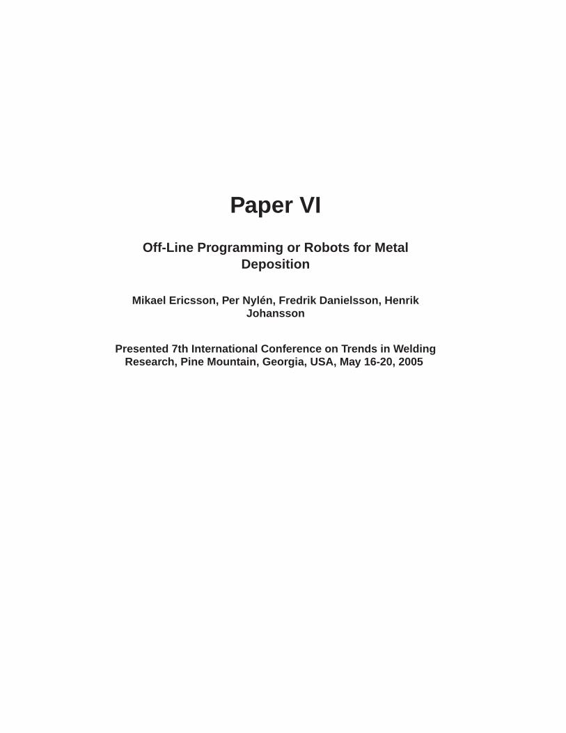
steel 316L. Figure 9 shows a snapshot from the TIG process. An arc of plasma is formedbetween the electrode and the base plate. The process was shown to be rather sensitivewith regard to the process parameters needed to obtain the desired shape of the depositedmetal. The weld torch had to be inclined 20 degrees from the vertical axis. The depositdirection is from left to right in Figure 8. The base plate had to be clamped very firmly toa fixture in order to avoid deformation and to enable efficient heat transportation.
Figure 8: Metal Deposition by TIG welding.
In the TIG experiments Automatic Voltage Control (AVC) was used to maintain an opti-mum electrode distance of 1.5 mm. The process parameters used for the welding opera-tion can be listed as follows:
• Weld speed : 3.0 mm/s
• Wire feed : 1.1 mm/s
• Weld current : 120 Amp

157
Experiments in which a rectangular solid box was manufactured, were performed line byline. The part to be manufactured was 40.6 mm wide, 100 mm long and 18mm high. Itwas initially made by 14 layers without any overlap of the weld seam i.e. the distancebetween the centres of each seam was chosen to be equal to the width of the seam. Itwas, however, shown that an overlap between seams is necessary. New deposit trials wereperformed by taking a weld seam overlap of 2.7mm. The number of seams and layerswas reduced to five and four respectively. Better results were achieved this time as thelayers were attached to each other and no discontinuities were observed. It was, however,observed that at some locations of the deposit the seams were not straight but deviated ina zigzag fashion. It was shown that the process was sensitive to slight deviations in thewire feed angle. Another observation was that edges occurred at the boundaries of theseams, Figure 9. This was shown to be due to partial oxidation of the deposited metal andhence the adjacent seams did not join perfectly.
Experiments were then performed using the Nd-Yag laser cell. Figure 10 shows the solidbox part. Each layer had an individual starting corner and a zig-zag movement from thiscorner had to be performed. A counter path was also used for each layer. It was alsoshown that it was necessary to adjust the wire feed rate and the laser power continuouslyduring the deposit. A sensor-based control system would be necessary to be able to fullyautomate the process. Figure 11 illustrates the necessity of these continuous adjustmentswhere a rectangular shape has been made. The left shape was performed without anyadjustments of the process, whilst the right shape was performed with continuous manualadjustments.
Figure 9: Edges along the seam after four layers.
Visual inspection of the cross-section revealed a fully dense material without any pores,Figure 12. Further work is planned to develop a process window in which a stable processis ensured. Microstructure evaluations and the mechanical testing of material propertieswith the aim of securing the functional performance of the parts are also planned.

158
Figure 10: The solid box geometry manufactured using a Nd-Yag laser cell.
Figure 11: Deposit without continuous process control (left) and with continuous processcontrol (right).
Figure 12: Cross section of the solid box geometry.

159
5 Summary and Conclusion
Three different methods for the off-line programming of robot paths were evaluated inthis paper. Two different geometries were considered; a rectangular solid box and a morecomplex geometry. Computer programs were developed to generate optimal robot pathsfor these geometries. All three methods were shown to be capable of generating the pathsfor the geometries. The major drawback encountered in the use of a CAM module forpath generation is that the software has been developed for milling, which means that itsfunctionality for Metal Deposition is limited. Individual paths for each deposit are needed,thus making the method more time-consuming for complex parts. The method using poly-mer Rapid Protyping software had a higher functionality since different starting pointsfor each layer were automatically defined. A drawback with this method, though, wasthat individual layer thicknesses could not be defined and that scaling procedures werefound to be necessary. The most flexible method seems to be the adaptation of ComputerAided Robotic (CAR) software. Using this method, a fully automated path generationseems possible, even for complex-shaped parts. Another advantage with this solution isthat only one system is needed for both path generation and for robot simulation. Furtherwork is however needed to evaluate the use of the method for more complex-shaped parts.The welding experiments showed that it was possible to manufacture fully dense parts,although the continuous control of process parameters is a requirement. Development ofa sensor-based control system is therefore under way. The present study seems to providean efficient way of manufacturing parts by means of the process of metal deposition. Thefinal quality of the product in terms of accuracy, finish and mechanical properties can beimproved further by examining different aspects of the process, such as heat transfer andmicrostructure, thus enabling more optimized weld parameters. The development of asimulation tool that can predict part temperature and distortion during deposition wouldalso be a worthwhile innovation. Optimal robot speeds, and trajectories related to shrink-age and distortion can thus be automatically defined. Such a simulation tool softwaresystem can by accomplished by linking the CAR software with Finite Element softwarein the same manner as was done in previous work regarding welding [7].
6 Acknowledgement
The authors wish to acknowledge the assistance in the experiments by Mr Kjell Hurtig andMr Mats Högström of University Trollhättan/Uddevalla and Mr. Peter Jonsson and Mr.Ingmar Fransson of Volvo Aero Corporation, Trollhättan for their help and encourage-ment. Mr. Alastair Henry of University of Trollhättan/Uddevalla for linguistic revision.The authors also wish to acknowledge the initial simulation work performed by Mr ManuSinghal. The work was funded by the EC Structural Founds and Innovatum Teknik.

160
References
1. M. L. Griffith, D. M. Keicher, C. L. Atwood, J. A. Romero, J. E. Smugeresky, L. D.Harwell, D. L. Greene, Free Form Fabrication of Metallic Components using LaserEngineered Net Shaping (LENSo), proceedings of the Solid Freeform FabricationSymposium, pp. 125. August 12-14, 1996, Austin, TX
2. G. Bolmsjö, M. Olsson, K. Brink, Off-line programming of GMAW robotic systems- a case study, Int J. for joining of Materials, 9, pp. 86-93, 1997
3. Y. F. Yong, J. A. Gleave, J. L. Green, and M. C. Bonne, Off-line programming ofrobots, Handbook of Industrial Robotics, New York, John Wiley & Sons, (1985)
4. R. Bernhardt, Robot Calibration, pp. 3-55, London: Chapman & Hall, (1993)
5. Zhang Y., Chen Y, Li P, Alan T. and Male A, Weld deposition-based rapid prototyp-ing: a preliminary study, Journal of Materials Processing Technology 135 (2003)347-357
6. Pennsylvania State University/Mechanical Engineering Department. http://www.me.psu.edu/lamancusa/ rapidpro/ index.htm [2005-04-18]
7. M Ericsson, Simulation of robotic TIG-welding, pp 5-9, licentiate thesis, LundsUniversity (2003)