Embed Size (px)
Citation preview

The Space Congress® Proceedings 1989 (26th) Space - The New Generation
Apr 27th, 2:00 PM
Paper Session III-A - The Mobile Servicing System - A System Paper Session III-A - The Mobile Servicing System - A System
Description Description
Andrew S. Jones Deputy Director, Canadian Space Station Program
V. K. Agarwal Systems Engineering, Canadian Space Station Program
R. Hayes APM Design and Development, Canadian Space Station Program, Remote Manipulator Systems Division, Spar Aerospace Limited, Toronto
Follow this and additional works at: https://commons.erau.edu/space-congress-proceedings
Scholarly Commons Citation Scholarly Commons Citation Jones, Andrew S.; Agarwal, V. K.; and Hayes, R., "Paper Session III-A - The Mobile Servicing System - A System Description" (1989). The Space Congress® Proceedings. 16. https://commons.erau.edu/space-congress-proceedings/proceedings-1989-26th/april-27-1989/16
This Event is brought to you for free and open access by the Conferences at Scholarly Commons. It has been accepted for inclusion in The Space Congress® Proceedings by an authorized administrator of Scholarly Commons. For more information, please contact [email protected].

MSS-RP-8911
The Mobile Servicing System - A System Description
Presented at the
26th Space Congress April 25-28, 1989
Andrew S. JonesDeputy Director, Canadian Space Station Program
V.K. AgarwalSystems Engineering, Canadian Space Station Program
R. Hayes
APM Design and Development, Canadian Space Station ProgramRemote Manipulator Systems Division
Spar Aerospace Limited, Toronto
System Description of Mobile Servicing System (MSS) for Space Station Freedom
Abstract
This paper is a systems description of the Mo bile Servicing System (MSS) to be provided by Canada, an International Partner to the NASA Space Station Freedom. The paper desf nbes space segment, ground segment, and support systems.
Spar is the prime contractor to the National Research Council of Canada (NRCC). The MSS will provide the functional capabilities for Space Station Freedom construction, maintenance, deployment, and retrieval of Free Flying Spacecraft and servicing of at tached payloads.
7-1

MSS-RP-8911
1.0 Introduction
The Mobile Servicing System (MSS) is Canada's contribution to the International Space Station - Freedom Programme. The programme is executed by Spar Aerospace, the prime contractor, under the aus pices of the National Research Council of Canada (NRCC).
The MSS will play a predominant role in:i) Space Station construction and assembly;
ii) Transportation on the exterior of the Station;
iii) Payload handling including deployment, re trieval, and berthing of payloads and the NSTS orbiter vehicle.
iv) Space Station maintenance in the EVA environ ment.
v) Attached payload servicing in the EVA environ ment.
vi) EVA crew activity support.
vii) Support of Space Station Safe Haven operation.
The overall MSS consists of a space segment, a ground segment and support systems.
The elements of the MSS are described below; and typical MSS operations outlined.
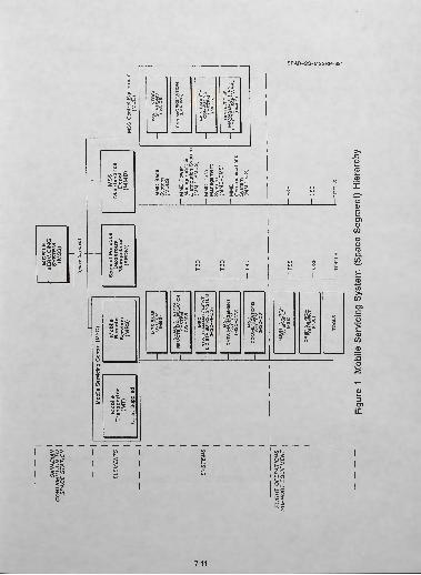
2.0 The MSS - Space Segment
The space segment hierarchy is shown in Figure 1. It consists of three flight elements, the MSC (Mobile Servicing Centre), the SPDM (Special Purpose Dex terous Manipulator), and the MMD (MSS Mainte nance Depot) and a sub-element the MCE (MSC Control Equipment).
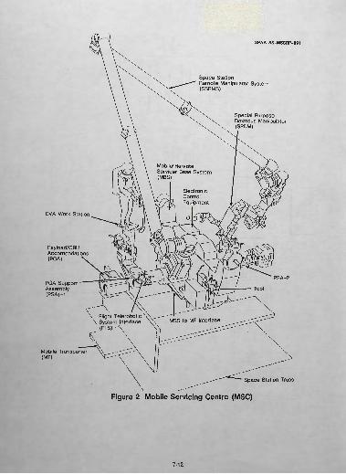
2.1 The MSC
An overall view of the MSC is shown in Figure 2. The MSC itself is comprised of two elements, the MRS (Mobile Remote Servicer) and the MT (Mobile Transporter). The MT is to be supplied by the United States, and it provides the MSC with translation, turn ing, and plane change capability on the space station trusses. The MRS is made up of a number of major
systems. The MBS (MRS Base System) provides the structure which interfaces with the Mobile Transpor ter, and supports the remaining systems of the MSC and payloads including the relocatable SSRMS (Space Station Remote Manipulator System) which is pro vided as a system of the MSC.
The MBS is illustrated in Figure 3. In this figure the SPDM and SSRMS are shown on the MBS in their stowed configuration and the payload support adapters deployed as they would be in service. Some of the key features of the MBS are given in Table 1 below.
Mass = 954 KgSize = 6.4 m x 4.6 m x 2.5 mNSTS Cargo bay length = 2.22 m
(launch configuration) NSTS interface 2 trunnions and 1 keel fitting
Table 1 MBS Key Features
The construction of the MBS is the subject of a trade study currently in progress between conventional aluminum alloy and composite material construction. The MBS is passively thermally controlled by the use of multi-layer insulation and exposed anodized sur faces. Temperature control is augmented by thermos tatically controlled heaters of approximately 80 W. The equipment supported by the MBS during launch or in orbit is listed in Table 2 below.
SSRMSSPDMFTS (U.S. Flight Teleoperator System)EVA AstronautsPayloads, Payload Pallets, ORUs, etc.MSC PMDS Power Management and Distribution SubsystemMSC CS (Lights, CCTVs, Pan & Tilt Units, Antennae, RF equipm< it)MSS and User Tools EVA Workstation
Table 2 MBS Mounted Equipment
The SSRMS has evolved from the Shuttle Remote Manipulator System (SRMS or "Canadarm").
7-2

MSS-RP-89H
Whereas the SRMS is a six-degree-of-freedom arm fixed at the shoulder end to the orbiter longeron with progressively smaller joints leading to a single end effector at its free end; the SSRMS is a symmetrical seven-degree-of-freedom arm with an end effector at each end. Thus the SSRMS is capable of relocating itself about the space station on appropriately located and outfitted Power Data Grapple Fixtures (PDGFs). PDGFs are also provided as attachment fixtures for MSS relocatable elements/systems on the MSC allow ing considerable flexibility in operations. Some key features of the SSRMS are given in Table 3 below.
Mass = 936 KgLeading Dimensions (deployed) =
16.8 m length 1.51 m offset
Comprises 7 DOF with two LEEs Deployed Frequency (typical) Unload 0.005 Hz Loaded (maximum payload) 0.15 Hz End point applied force (typical) 80 N Stopping distance(joint run away worst case) 600 mm
Table 3 SSRMS - Features
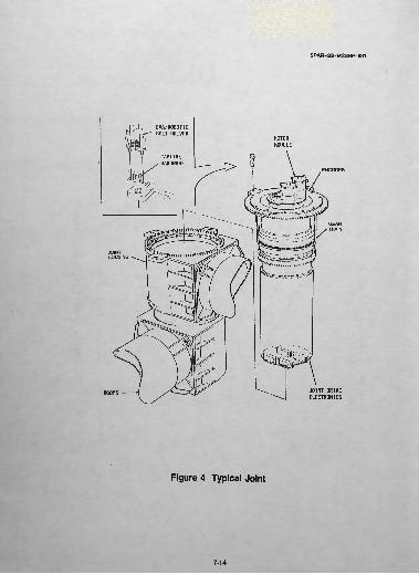
The SSRMS is essentially fail operational and fail safe after a second failure, with considerable self monitoring to ensure no uncommanded motions or joint run aways occur. A typical SSRMS joint is shown in Figure 4. Each joint has an integral Joint Electronics Unit (JEU) that provides the servo control of the high speed motor module. The motor torque is transmitted through high speed and low speed gear boxes to the joint structure. The low speed gear box is specially designed to minimize the joint backlash and provide high stiffness in the drive axis. Some key features of the SSRMS joints are listed in Table 4 be low.
Mass =Radge of travel =Max speed =Max torque (stall) =
55.3 Kg+/- 180 degrees
0.083 rads/sec (wrist)3600 Nm
Gear ration Gl x G2 = Efficiency - forward =
- back = Encoder (output) =
1840 82% 78%
18 bit
Table 4 Joint Data (typical)
Each joint is driven by a motor module. The mo tor module contains prime and secondary drives each with a brushless DC motor. Commutation and rate data being generated by a resolver. Each motor shaft is attached to a brake. The brake is designed "power off - brake on" so as to avoid a free joint in the event of a loss of power. Typical motor module data is given in Table 5 below.
Mass =Motor torque = Frictional torque = Brake slip (static) = Motor power = Brake power = Resolver =
5 Kg2 Nm
0.1 Nm1.2 Nm
178 W (at stall)20 W (continuous)
16 bit
Table 5 Joint Motor Module
At each end of the arm is located a force moment sensor (FMS) to allow control of applied forces. Ta ble 6 below indicates the expected FMS range and accuracy.
ForceTorque
Range
<1650 N<6500 Nm
Accuracy
2.0%0.1%
Table 6 Force Moment Sensor (FMS) Performance
7-3
MSS-RP-8911
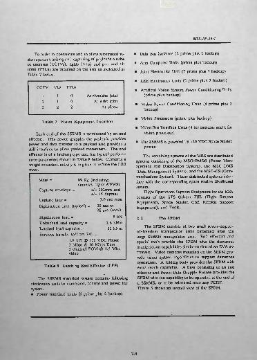
To assist in operations and to allow automated vi sion system tracking and capturing of payloads a suite of cameras (CCTVs), lights (VLs) and pan and tilt units (PTUs) are required on the arm as indicated in Table 7 below.
CCTV
112
VLs
112
PTUs
002
At shoulder jointAt wrist joint
At elbow
Table 7 Vision Equipment Location
Each end of the SSRMS is terminated by an end effector. This device grapples the payload, provides power and data transfer to a payload and provides a stiff interface to allow payload maneuvers. The end effector is of a latching type and has typical perform ance parameters shown in Table 8 below. Currently a weight reduction activity is in place to reduce the LEE mass.
Mass = 99 Kg (includingcameras, lights &FMS)
Capture envelope = +/- 102mm and+/- 15 degrees
Capture time = Rigidization time (typical)
Rigidization load = Unlatched load capacity = Latched load capacity = Services transfer to/from P/L =
3.0 sec max20 sec to 28 sec (max)
8 kN 1.6 kNm 80 kNm
1.8 kW @ 120 VDC Power 3 Mbps & 10 Mbps Data 3 channel FOM @ 4.5 Mhz video
Table 8 Latch ' ig End Effector (LEE)
The SSRMS electrical system contains following electronics units to command, control and power the system. • Power Interface Units (2 prime plus 2 backup)
• Data Bus Isolators (2 prime plus 2 backup)
• Arm Computer Units (prime plus backup)
• Joint Electronics Unit (7 prime plus 7 backup)
" LEE Electronics Units (2 prime plus 2 backup)
» Artificial Vision System Power Conditioning Units (prime plus backup)
• Video Power Conditioning Units (4 prime plus 2 backup)
• Vision Processors (prime plus backup)
» Video Bus Interface Units (4 for cameras and 1 for vision processor)
• The SSRMS is powered by 120 VDC Space Station power.
The remaining systems of the MRS are distributed systems consisting of the MSC-PMDS (Power Man agement and Distribution System), the MSC-DMS (Data Management System), and the MSC-CS (Com munications System). These distributed systems inter face with the corresponding space station distributed system.
Flight Operations Support Equipment for the MSS consists of the STS Orbiter FSE (Flight Support Equipment), Space Station OSE (Orbital Support Equipment), and Tools.
2.2 The SPDM
The SPDM consists of two small seven-degree- of-freedom manipulator arms patterned after the large SSRMS manipulator arm. End effectors and special tools provide the SPDM with the dexterous manipulation capabilities similar to that of an EVA as tronaut. Video cameras mounted on the SPDM pro vide vision system capabilities to support dexterous operations. A folding body provides the SPDM with extra reach capability. A base consisting of an end effector and Power Data Grapple Fixture provides the SPDM with the capability to be operated at the end of a SSRMS, or to be relocated onto any PDGF. Figure 5 shows an overall view of the SPDM.
7-4
MSS-RP-89H
2.3 The MMDThe MMD provides a Maintenance Depot for the
MSS, as well as a "home base" to store equipment when not in use. The MMD comprises the structural system, and distributed systems that accommodate any of the relocatable elements/systems of the MSS (eg. SSRMS, SPDM, EVA Workstation). The MMD also accommodates MSS Orbital Replaceable Units (ORUs), Tools, MSS maintenance fixtures, and spe cial integration and test equipment.
2.4 The MCE
The MCE comprises an EVA-WS (EVA Work station) and any special MSS required hardware re quired to be added to the standard IVA Work Station as well as the special MSS related software that runs in the IVA - WS and the Space Station Data Manage ment System.
3.0 MSS Phasing
The MSS is designed to be implemented in a phased manner onto the space station. The Phase I space station will require approximately twenty shuttle missions consisting of assembly flights, outfitting of modules, and logistics flights for crew rotations and resupply. The assembly of the space station is ex pected to commence in 1994/95, with completion of Phase I in 1998. The space station will have an Early Man-Tended Capability (EMTC), in that the crew can enter the space station and perform IVA tasks on the fourth flight, and be permanently manned from about the tenth flight or earlier.
Figure 6 shows the MSS space segment phased implementation on the Phase I space station. On flight two the Phase 1 MSC consisting of the MRS with a SSRMS is required to be integrated onto the MT. On later flights the SPDM, MMD and second MSC POA (Payload ORU Accommodation) will be added. As can be seen by the early manifest of the Canadian MSS, it plays an important role in space station as sembly.
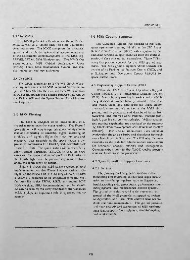
4.0 MSS Ground Segment
The Canadian support role consists of real time space operations support, initially at the JSC Space Station Control Center (SSCC) with migration to the Canadian Ground Support facilities after the initial as sembly of the space station is complete. Figure 7 illus trates the present concept for the MSS ground seg ment. The MSS ground segment within Canada will consist of an Engineering Support Centre (ESC), and a Utilization and Operations Centre (U&OC) for space station users.
4.1 Engineering Support Centre (ESC)
Within the ESC is a Space Operations Support Centre (SOSS), an an Integrated Logistics System (ILS). Sustaining engineering is on-line and available using dedicated project team personnel. The real time voice, video and data from the space station communications network arrives at the SOSS via a gateway and is processed and distributed to control, recording, and analysis work stations. Parallel play back is possible for off-line activities. MSS simulation and training capabilities are provided by the support ing Manipulator Development and Simulation Facility (MDSF). The overall architecture uses common workstation design as a basis, and this allows for maxi mum flexibility in facility use. The ILS uses the same networks as the ESC but retains its own workstations for inventory control, analysis and management. Communication links to the U&OC enable program monitor functions to be performed.
4.2 Space Operations Support Functions
4.2.1 On LineThe primary on line ground function is the
monitoring and recording of real time flight data in order to provide appropriate input to diagnostics, troubleshooting aids, procedures, performance moni toring systems, and maintenance control systems. The ground provides capability for command and control of the MSS primarily in support of system configuration, and test. This control does not in clude real time manipulation. The ground provides real time analysis and evaluation of MSS perform ance that suppons fault isolation, troubleshooting, and workarounds.
7-5

MSS-RP-8911
4.2.2 Off LineA major function on the ground is simulation.
The simulation capability, both real time and non-real time, is used for operations planning, procedure vali dation, crew training, system performance validation, contingency situations, and engineering analysis. The ground also performs off line trend analyses in order to predict failures, on-orbit performance, and support spares analysis. The ground performs spares analysis and recommendation using automated provisioning databases. The ground provides the planning and scheduling capability that is used for strategic, tactical, increment, and execution planning.
5.0 Support Systems
In support of the design, development, verifica tion and operation of the MSS are three systems, the MDSF (Manipulator Development and Simulation Facility), the SSE (the MSS Software Support Envi ronment), and CTMIS (the Canadian Technical and Management Information System).
5.1 MDSFThe MDSF is both a development and validation
facility and an operational support and analysis facil ity. It is a series of processors and graphics hardware and advanced kinematics and control system analysis software that provides both non-real time and real time simulations of system kinematics dynamics, con trol systems and structural responses. The system has interfaces with flight and engineering model hardware and software to support system verification. It is illus trated in Figure 8.
5.2 SSEThe Software Support Environment is a series of
hardware and software items that allow a modern computer aided software engineering development and verification environment for the considerable amount of flight software and ground software. Ada has been baselined as the programming language for flight and ground software.
5.3 CTMISThe Canadian TMIS is a VAX based network of
all major subcontractors, the government (NRCC) and
prime contractor. It is a menu driven data base, elec tronic mail and file transfer system. CTMIS allows program data, news, and messages to be exchanged and maintained on a program wide basis. Links to NASA-TMIS have also been established. CTMIS and SSE are fully integrated and share common hard ware and communication links where appropriate.
6.0 MSS - Control
The MSS Operations can be commanded and controlled from IVA - Control station in the station nodes or cupolas, the MSS - EVA - Work Station or from the orbiter control station. The result of these different configurations is that the station DMS and C&T subsystem is often embedded in the overall MSS control loop. There is also the ability to check out the MSS health from the space station control centre on ground. Figure 9 illustrates the complexity of the MSS control paths.
7.0 MSS On-Orbit Operations Functions
Since MSS elements/systems are manifested in a phased manner during the space station assembly, the functional capabilities of the MSS increase accord ingly. The following describes the complete MSS on- orbit operations functions.
7.1 Space Station Construction and AssemblyThe MSS space station construction and assembly
operations include the following:
i) Assembly of modules, nodes, and airlocks onto the space station structure.
ii) Construction of space station truss structures in cluding installation of utilities.
iii) Installation of thermal radiators, RCS modules and tankage, inboard and outboard solar arrays, payload interfaces and payloads.
Assembly activities can be grouped in the following categories:i) Large scale Manipulation by the use of the SSRMS
for grappling, translation, rotation, and position ing of space station hardware.
7-6

MSS-RP-8911
ii) Dexterous Manipulation by the use of EVA or SPDM for translation, rotation, positioning or grappling of space station hardware requiring man or man-like capabilities.
iii) Transport by the use of the MSC for relocation of space station hardware from one location to an other location that is beyond the reach of a ma nipulator.
iv) Payload Track and Capture/Release by the use of the SSRMS for acquisition of an orbiter or free flyer for the purpose of securing it structurally to the station. Also, the reciprocal action of releas ing the vehicle under controlled conditions.
v) Holding or Positioning of payloads by the use of the MSS for restraint or securing of space station hardware temporarily, to enable operations (such as attachment).
vi) Other MSS Operations anticipate the use of MSS for inspection and checkout of space station ele ments, and use of MSS for deployment of space station hardware such as solar arrays.
7.2 Transportation
The MSC provides the capability to transport suit ably outfitted equipment on the space station truss. The MT portion of the MSC provides the mobility mechanisms for translation, turning, and plane chang ing on the trusswork. Cargo that can be transported on the MSC includes the following:
i) Space station construction and assembly cargo.
ii) Attached payloads.
iii) Free-Flyers, (with and without payloads).
iv) Space station maintenance and logistics cargo (including that for the MSS).
v) EVA astronauts.
Also, growth capabilities will be provided for:
vii) Orbital Maneuvering Vehicle (OMV), (with and without payloads),
viii) Payloads (to be staged/destaged from OMVs, Free-Flyers, Orbital Transfer Vehicle).
Transportation is considered one of the MSS pri mary functions, as wells as an operations activity asso ciated with other MSS primary functions such as as sembly, maintenance, and servicing.
7.3 Orbiter Berthing and Payload HandlingThe MSC has the capability to perform orbiter
berthing and the following payload handling opera tions: i) Capture,
ii) Maneuvering,
iii) Positioning,
iv) Berthing and deberthing,
v) Release.
In performing these operations, the MSS has the capability to limit forces and torques at the end effec tor interfaces.
7.4 Space Station MaintenanceThe MSS provides capabilities to maintain the
space station. Space station maintenance also in cludes MSS maintenance, and hence the MSS is de signed to maintain itself on-orbit. The complete MSS consisting of the MSC, MMD, and SPDM under con trol from the MCE provides for space station mainte nance. Space station EV maintenance operations can be categorized as follows:
i) ORU Changeout
- ORU changeout includes gaining access to the ORU, removing the faulty ORU, installing the re placement, and closing out access to the ORU.
ii) Cleaning
- The removal of foreign material (particles or depos its) from the surface of an item.
iii) Inspection
- The visual examination of an item by support direct (EVA crew), or indirect (use of MSS video) ob servation.
iv) Adjustment and Alignment
7-7
MSS-RP-89/1
- Includes the manipulation of equipment to return equipment to an intolerance condition.
v) Lubrication
- The MSS supports this function of introducing lu bricant by its dexterous manipulation capability. Lubrication accomplished by replacing sealed units is either ORU changeout or a replenishment activity.
7.5 Attached Payload ServicingThe MSS supports servicing of the space station
attached payloads in the extravehicular (EV) environ ment using special tools and servicing equipment. MSS servicing operations include the following activi ties: i) Payload Assembly
- Includes installation (integration), checkout, recon figuration, upgrade, or disassembly of payloads.
ii) Restoration
- Inspection, safing of hazardous systems, ORU re placement, repair (MSC supports transportation to IVA maintenance work area for ORU repair), testing and calibration on user systems down to the ORU level.
iii) Consumables Replenishment
- Fluids replenishment, re-supply of raw materials, and harvesting of products.
iv) Temporary Storage
- ORUs or ORU pallets, tools or tool pallets, cus tomer furnished servicing equipment.
v) Transportation
- Payloads, ORU pallets, customer furnished servic ing equipment.
7.6 Crew EVA SupportThe MSC provides the capability to transport and
position EVA astronauts about the space station. The provision of an EVA workstation allows an EVA crew- member to control the MSC, either from the MSC, or with the workstation at the end of the SSRMS. A Manipulator Foot Restraint (MFR) is also provided to accommodate an EVA crewmember on the end of the SSRMS.
The MSS provides EVA mobility and translation aids such as handholds, foot restraints, and tether at tachments. Also, lighting and video monitoring is pro vided to support EVA. EVA power tool outlets and tool accommodations are also provided.
7.7 Safe Haven SupportThe MSS supports the space station safe haven
requirement to provide a means of rescue for crew from isolated modules. A number of safe haven sce narios are being analysed and evaluated by NASA. One of the scenarios is that a node depressurizes and crew become isolated in either the Japanese Experi ment Module (JEM), or the JEM Equipment Logistics Module (ELM). Similarly crew could become iso lated in the European Space Agency (ESA) module. The MSS rescue scenarios include umbilical hookup to the isolated module (s), transporting the isolated modules to another docking port, or transporting the EVA rescue crew, and the isolated crew after they have donned EMUs (Extravehicular Mobility Units).
8.0 Design and Development Approach
The overall design and development approach is based in many areas on proven methods used for the production of space systems, however, the MSS un like most space systems (but similar to a number of other space station elements) will have elements that are integrated on orbit without prior ground integra tion. Thus, physical and functional simulators of in terfaces will be produced and used to validate systems prior to launch, both a DMS test bed and integration and checkout of flight hardware and software linked into MDSF simulations will be used in this way.
7-8

MSS-RP-89H
The overall model philosophy is one established to minimize cost and risks thus primarily a prototype ap proach is used. Qualification hardware is only pro duced in support of units that are produced in quan tity where a protoflight approach would not be cost effective-
Engineering and breadboard models of critical ar eas are planned to support engineering development and to resolve areas of technical risk. This includes the rapid prototype of flight systems in Ada.
A complete independent validation and verifica tion of all critical software is planned.
9.0 Advanced Technology Development (ATD)
In parallel to the main MSS program a supportive ATD program has been put in place. This evaluates
more advanced concepts or design solutions and prior to each PDR an implementation review is held to con sider if a more advanced solution should be incorpo rated into the baseline. Consideration of technical risk, performance improvements, costs, schedule im pact, and fall back options are made. Typical studies at present include:
- Collision avoidance algorithms - Vision systems - Materials Development - Expert System Applica tions
10.0 ConclusionThe paper provides an overall description of the
MSS, a complex and important part of the space Sta tion Freedom. In such an overview many details must be omitted. Further information on the MSS can be found in the references.
7-0
MSS-RP-89/1
11.0 References
1. Mobile Servicing System - Flight Operations and Support
D.A. Bassett, J.A. Middleton, W.J.G. Brimley and T.W. Young 39th Internal Congress of the IAF, 8 October 1988
2. The role of the MSS on Space Station
H.L. Werstiuk and D. Gossain, IEEE Interna tional Conference on Robotics and Automation, 30 March 1987
3. Technology Research and Development associ ated with the MSS. F.R. Vigneron, R.D. Coswell, S.S. Sachdev, R. Ravindran, 4th CASI Confer ence on Astronautics, 3 November 1987
4. The Structural Design of the MSS under Multiple Constraints
E. Quittner, et al; 6th CASI Conference
5. Concept Design of the SPDM of the MSS
M. Brouillette et al; 5th CASI Conference on As tronautics, 15 November 1988
6. MSS Operations on the Space Station, W.J. Brimley, G. Beyer, H. Kleinburg 4th CASI Con ference on Astronautics, 3 November 1987
Acknowledgments
The work presented in this paper has been per formed at Spar Aerospace Limited, Remote Manipu lator Systems Division under DSS/NRCC Space Divi sion. The authors thanks NRCC, Spar and its subcon tractors for their contribution to the work described.
7-10
CA
NA
DIA
N
1 C
ON
TRIB
UTI
ON
TO
\
SP
AC
E S
TA
TIO
N
' 1 1I
Mob
ile S
ervi
cing
Cen
tre (
MS
C)
ELE
ME
NTS
\
Tra
nsp
ort
er
| (M
T)
U.
S. S
uppl
ied
1 1 i 1 1 S
YS
TEM
S | 1 1
FLI
GH
T O
PE
RA
TIO
NS
'
SU
PP
OR
T E
QU
IPM
EN
T
I
Mob
ile
Rem
ote
Ser
vice
r (M
RS
)
—
MR
S B
AS
E
SY
ST
EM
(M
BS
)
SP
AC
E S
TA
TIO
N
RE
MO
TE M
AN
IPU
LAT
OR
S
YS
TE
M
(SS
RM
S)
MS
C
PO
WE
R M
AN
AG
EM
EN
T
& D
ISTR
IBU
TIO
N S
YS
TE
M
(MS
C-P
MD
S)
MS
C
DA
TA
MA
NA
GE
ME
NT
S
YS
TE
M
(MS
C-D
MS
)
MS
C
CO
MM
UN
ICA
TIO
NS
S
YS
TE
M
(MS
C-C
S)
FLIG
HT
SU
PP
OR
T E
QU
IPM
EN
T (F
SE
)
OR
BIT
SU
PP
OR
T E
QU
IPM
EN
T (O
SE
)
TOO
LS
MO
BIL
E
SE
RV
ICIN
G
SY
STE
M
(MS
S)
Spac
e Se
gmen
t
Spe
cial
Pur
pose
D
exte
rous
M
an
ipu
lato
r (S
PD
M)
— T
BD
- T
BD
- T
BD
~ F
SE
— O
SE
— T
OO
LS
MS
S
Main
tenance
D
epot
(M
MD
)
~~ M
MD
Bas
e S
yste
m
(MD
BS)
~" M
MD
Pow
er
Man
agem
ent
& D
istri
butio
n S
yste
m
(MM
D-P
MD
S)
— M
MD
Dat
a M
anag
emen
t S
yste
m
(MM
D-D
MS
)
- M
MD
C
omm
unic
atio
ns
Sys
tem
(M
MD
-CS
)
MSS
Con
trol
Equ
ipm
ent
(MC
E)
IVA
CO
NT
RO
L -
ST
AT
ION
S
(IVA
CS
)
EV
A W
OR
KS
TA
TIO
N
—
(EV
A W
S)
MS
S F
AC
ILIT
Y
_
CO
MP
UTI
NG
S
YS
TE
M
(MFC
S)
OP
ER
ATI
ON
S
_
MA
NA
GE
ME
NT
AN
D
CO
NT
RO
L S
OF
TW
AR
E
(OM
CS
)
- F
SE
c ^ :
- O
SE
* 0 0 :
-TO
OL
S
^ Ci
Figu
re 1
M
obile
Ser
vici
ng S
yste
m (
Spac
e Se
gmen
t) H
iera
rchy
SPAR-SS-MSSRP-891
EVA Work Station
Pay!oad/ORUAccomondations(POA)
PDA SupportAssembly(PSAJ-1
Space StationRemote Manipulator System(SSRMS)
Special Purpose Dextrous Manipulator (SPDM)
ElectronicControlEquipment
\ Flight Telerobotic YV~-—"~"' „, , \ System Interface \N MBS to MT Interface
(FTS)'
Mobile Transporter (MT)
Space Station Truss
Figure 2 Mobile Servicing Centre (MSC)
7-12

^v-^
.-ss
riw
-'' ,
;
IGI
HOPK
Figu
re 3
M
RS B
ase
Syst
em (
MBS
)
SPAR-SS-MSSRP-891
( M. EVA/ROBOTIC
e^- BOLT DRIVERMOTOR MODULE
ENCODER
BOOMS -J JOINT DRIVE ELECTRONICS
Figure 4 Typical Joint
7-14

PO
WE
R D
ATA
G
RA
PP
LE F
IXTU
RE
UPP
ER B
OD
Y W
ITH
ELE
CTR
ON
ICBO
XES
UPP
ER /
LO
WER
BO
DY
PIT
CH
JOIN
T
UP
PE
R B
OD
Y
YA
W A
ND
PIT
CH
JO
INTS
TV
CA
ME
RA
LATC
HE
D
EN
D E
FFE
CTO
R
TV
CA
ME
RA
SP
EC
IAL
TOO
L
\ FO
RC
E M
OM
EN
T "•\
SE
NSO
R
LOW
ER B
OD
Y W
ITH
ELE
CTR
ON
IC
BOXE
S A
ND
TO
OLS
ELB
OW
PIT
CH
JO
INT
UPP
ER A
RM
W
ITH
WIR
ING
LOW
ER
BO
DY
R
OLL
JO
INT
STER
EO C
AM
ER
AS
AN
D L
IGH
TS
0) 5 ID
Figu
re 5
SP
DM C
onfig
urat
ion

MSS
Pha
se
Equi
pmen
tCa
pabi
lities
Flig
ht
0>
(SS
Phas
e I)
0
1
MT,
IVA
CS,
MFC
S
MBS
Stru
ctur
e In
terfa
ces
POA-
1 To
ols
IVA
Con
trols
for
MSS
Base
for S
SRM
S FT
S ac
com
odat
ion
Tran
spor
ting
paylo
ads
on S
S Lim
ited
P/L
serv
icing
MB
-1
MB
-2
SSRM
S
EVA
WS,
PM
DS,
DMS,
CS
SPDM
MM
D
POA
-2
Orb
iter b
erth
ing
Load
ing/
unlo
adin
g pa
yload
s Re
loca
tion
of S
SRM
S
Limite
d EV
A co
ntro
l of o
pera
tions
limite
d se
rvici
ng o
f MSC
with
out E
VA
Dexte
rous
task
s
Serv
icing
of M
SS a
t fixe
d lo
catio
n M
SS O
RU s
tora
ge c
apab
ilitie
s
Sim
ulta
neou
s tra
nspo
rt of
P/L
and
P/L
OR
U cr
adle
on
MSC
L-1
L-3
! 3) •o
Figu
re 6
M
SS E
quip
men
t and
Cap
abili
ties
by P
hasi
ng

SPAR-SS-MSSRP-691
MSS Ground Segment
EngineeringSupport Centre
(ESC)
Utilizations andOperations
Centre(U & OC)
Space OperationsSupport Centre
(SOSS)
Integrated LogisticsSystem
(ILS)
Figure 7 Current MSS Ground Segment Organization
7-17

CO
Gene
ric
Oper
ator
/Ins
truc
tor
Engineering
WS
Maintenance
Room (
Oct. 9
2)
^ CO
Figu
re 8
M
anip
ulat
or D
evel
opm
ent a
nd S
imul
atio
n Fa
cilit
y (M
DSF)
- Ar
tists
Con
cept

Ope
rato
r
Ope
rato
rto
Ope
rato
r <]
^
^
' *>
O
pera
tor
ssD
AT
A M
AN
AG
EM
EN
T
SY
ST
EM
OR
BIT
ER
C
ON
TR
OL
ST
AT
ION
1$$^m
m
OR
BIT
ER
II
_£PACE SEGMENT
GROUND SEGMENT MSS
ENGI
NEER
ING SUPPORT
CENTRE
OPERATOR
(SS CONTROL CENTRE)
5 3) to
Figu
re 9
M
SS C
omm
and
& C
ontro
l Arc
hite
ctur
e