Embed Size (px)
Citation preview

IOP Conference Series Materials Science and Engineering
PAPER bull OPEN ACCESS
Design and Development of In-pipe InspectionRobot for Various Pipe SizesTo cite this article Atul Gargade and Shantipal Ohol 2021 IOP Conf Ser Mater Sci Eng 1012012001
View the article online for updates and enhancements
You may also likeModelling of fluid-mechanical arc instabilityin pure-mercury HID lampsThomas D Dreeben
-
Laser vibrometry measurements ofvibration and sound fields of a bowedviolinPer Gren Kourosh Tatar Jan Granstroumlmet al
-
Plasmon flow control at gap waveguidejunctions using square ring resonatorsJianlong Liu Guangyu Fang Haifa Zhaoet al
-
This content was downloaded from IP address 6521228167 on 13122021 at 0146
Content from this work may be used under the terms of the Creative Commons Attribution 30 licence Any further distributionof this work must maintain attribution to the author(s) and the title of the work journal citation and DOI
Published under licence by IOP Publishing Ltd
RIACT 2020IOP Conf Series Materials Science and Engineering 1012 (2021) 012001
IOP Publishingdoi1010881757-899X10121012001
1
Design and Development of In-pipe Inspection Robot for
Various Pipe Sizes
Atul Gargade1
and Shantipal Ohol1
1Mechanical Engineering Department College of Engineering Pune India
E-mail gargadeaa14mechcoepacin
Abstract In-pipe inspection robots are designed to pull out the human role from work load
and risky working circumstances In this paper an in-pipe inspection robot version 2 (IPIR
version 2) is presented which composed of two driving leg systems two supporting leg
systems and a connecting body Novelty of version 2 is its stability and diameter adaptability
Stability of version 2 is enhanced by adding two supporting leg systems in version 1 and
diameter adaptability of version 2 is improved by optimizing its spring design All major
components of version 2 are designed safely Solid modelling of all robot parts and its
assembly is carried out in Solidworks 16 Mathematical modelling of version 2 is carried by
Lagrangersquos method A planetary geared DC motor with encoder (IG42E-104K) is used as
prime mover of IPIR version 2 This robot has mainly employed aluminium as structural
material To verify the efficacy of driving mechanism several experiments of version 2 are
conducted in horizontal pipes vertical pipes and couplings of 8 inches to 10 inches diameter
range This IPIR version 2 will be employed for offline visual checking of various pipe
components like horizontal pipes vertical pipes and couplings in water pipelines gas pipelines
and drain pipes etc
Keywords In-pipe inspection robot version 2 (IPIR version 2) driving mechanism
planetary geared DC motor defects
1 Introduction
From last couple of decades robotics is becoming one of the most quickly expanding fields As we
know variety of pipes is being used to build valuable lifelines like gas supply water supply and
sewerage systems in our modern community Therefore pipeline has become a crucial component of
conveyance In fact pipeline has become an integrated module of dissimilar types of sectors such as
power plants crude oil companies and suburban water supply agriculture field and so on But due to
the years of usage of pipelines defects like cracks aging and corrosion takes place Even blockages
are also seen in the pipeline Sometimes defects are taking place due to natural disasters and
mechanical damages from unbiased observer Therefore it becomes very difficult to search such
defects and their locations Thus maintenance plan of such pipelines should be scheduled If we
accomplish inspection activity by manual way then great amount of efforts labours and time is
required to dig out the pipes that are covered under the floor The utmost reason of inventing in pipe
inspection robot is to withdraw human being and come out with a fast and accurate inspection at low
cost [1 2]
RIACT 2020IOP Conf Series Materials Science and Engineering 1012 (2021) 012001
IOP Publishingdoi1010881757-899X10121012001
2
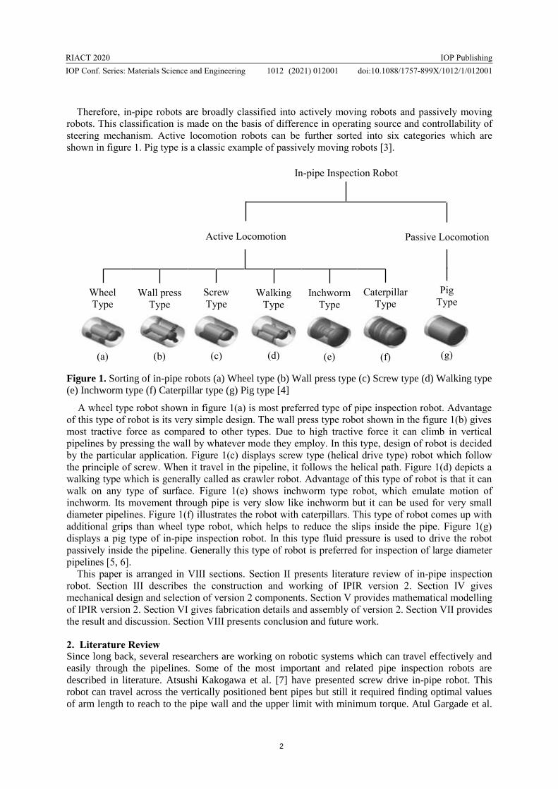
Therefore in-pipe robots are broadly classified into actively moving robots and passively moving
robots This classification is made on the basis of difference in operating source and controllability of
steering mechanism Active locomotion robots can be further sorted into six categories which are
shown in figure 1 Pig type is a classic example of passively moving robots [3]
Figure 1 Sorting of in-pipe robots (a) Wheel type (b) Wall press type (c) Screw type (d) Walking type
(e) Inchworm type (f) Caterpillar type (g) Pig type [4]
A wheel type robot shown in figure 1(a) is most preferred type of pipe inspection robot Advantage
of this type of robot is its very simple design The wall press type robot shown in the figure 1(b) gives
most tractive force as compared to other types Due to high tractive force it can climb in vertical
pipelines by pressing the wall by whatever mode they employ In this type design of robot is decided
by the particular application Figure 1(c) displays screw type (helical drive type) robot which follow
the principle of screw When it travel in the pipeline it follows the helical path Figure 1(d) depicts a
walking type which is generally called as crawler robot Advantage of this type of robot is that it can
walk on any type of surface Figure 1(e) shows inchworm type robot which emulate motion of
inchworm Its movement through pipe is very slow like inchworm but it can be used for very small
diameter pipelines Figure 1(f) illustrates the robot with caterpillars This type of robot comes up with
additional grips than wheel type robot which helps to reduce the slips inside the pipe Figure 1(g)
displays a pig type of in-pipe inspection robot In this type fluid pressure is used to drive the robot
passively inside the pipeline Generally this type of robot is preferred for inspection of large diameter
pipelines [5 6]
This paper is arranged in VIII sections Section II presents literature review of in-pipe inspection
robot Section III describes the construction and working of IPIR version 2 Section IV gives
mechanical design and selection of version 2 components Section V provides mathematical modelling
of IPIR version 2 Section VI gives fabrication details and assembly of version 2 Section VII provides
the result and discussion Section VIII presents conclusion and future work
2 Literature Review
Since long back several researchers are working on robotic systems which can travel effectively and
easily through the pipelines Some of the most important and related pipe inspection robots are
described in literature Atsushi Kakogawa et al [7] have presented screw drive in-pipe robot This
robot can travel across the vertically positioned bent pipes but still it required finding optimal values
of arm length to reach to the pipe wall and the upper limit with minimum torque Atul Gargade et al
In-pipe Inspection Robot
Active Locomotion Passive Locomotion
Walking
Type
(d)
Screw
Type
(c)
Inchworm
Type
(e)
Caterpillar
Type
(f)
Wall press
Type
(b)
Wheel
Type
(a)
Pig
Type
(g)
RIACT 2020IOP Conf Series Materials Science and Engineering 1012 (2021) 012001
IOP Publishingdoi1010881757-899X10121012001
3
[8] have proposed a wall pressed wheel type in-pipe inspection robot This robot can pass through
horizontal and vertical pipes of 140mm to 200mm diameter range It does not pass through bends and
couplings Muhammad Azri Abdul Wahed and Mohd Rizal Arshad [9] have presented wall pressed
wheel type pipe inspection robot which can pass through pipes of 150mm to 230mm diameter range
That robot can pass through horizontal pipes and inclined pipes of a slope not more than 30 degree It
cannot pass through vertical pipes and other elements of pipeline Hun-ok Lim and Taku Ohki [10]
have developed wall pressed wheel type pipe inspection robot That robot can pass through horizontal
pipes vertical pipes and lsquoTrsquo joints R K Jain et al [11] have proposed a virtual prototype of in-pipe
inspection robot That robot has employed scissor mechanism for inspection of large diameter pipeline
of 500mm to 1000mm diameter range Ankit Nayak and S Pradhan [12] have proposed an in-pipe
inspection robot which is combination of screw type and wall pressed wheel type robot They have
provided mathematical treatment and demonstrated the efficacy of developed mathematical model
They have presented initial conceptual prototype of pipe inspection robot
Majority of in-pipe inspection robots have used one of the basic types of mechanism directly
whereas some robots have used combination of basic types This paper presents a screw driven wall
pressed wheel type in-pipe inspection robot version 2 This version is configuration of screw type and
wall pressed wheel type robot This presented configuration is providing better stability and diameter
adaptability than existing screw driven wall pressed wheel type in-pipe inspection robot
3 Construction and Working of IPIR version 2
31 Construction and Working of IPIR version 1
IPIR version 1 was consisting of forward leg system backward leg system and a body That version
was able to pass through horizontal and inclined pipes of 10 inches diameter only Therefore its
diameter adaptability inside different pipe sizes was poor Weight of version 1 was 22 kg Due to high
weight its steerability in vertically pipe was very poor
Figure 2 Working model of IPIR version 1 [13]
Therefore IPIR version 2 has been developed to overcome the drawbacks of IPIR version 1
Stability of IPIR is improved in version 2 by adding two supporting leg systems Spring design of
version 1 is optimized to pass through pipes of 8 inches to 10 inches diameter range
32 Construction and Working of IPIR version 2
In-pipe inspection robot version 2 mainly composed of a forward leg system backward leg system
and a connecting body Both the leg systems are mirror images of each other in construction Each leg
system consists of two sub leg systems One is driving leg system with inclined wheels and another is
Lower
element
of a leg
Driving
leg
system
Supporting
leg
system
Rigid
body
Wheel
Upper
element of
a leg
RIACT 2020IOP Conf Series Materials Science and Engineering 1012 (2021) 012001
IOP Publishingdoi1010881757-899X10121012001
4
supporting leg system with straight wheels Driving leg systems of fore leg systems is mounted on the
DC motor shaft whereas supporting leg system is fixed on a robot body Both driving and supporting
leg systems consists of three legs which are framed at an angle of 120 degree to one another to travel
through pipes of 8 inches to 10 inches diameter range Each leg comprised of a lower element upper
element spring and a wheel which is shown in figure 3 To get better stability in vertical pipe wheels
of both the leg systems are knurled
Figure 3 Solid model of IPIR version 2
To get forward and backward motion of robot in spiral direction wheels of driving leg systems are
connected to top element at an angle of 15 degree Wheels of supporting leg systems are kept at 90
degree to get rolling motion in to and fro direction Springs are placed into lower element of each leg
which does help to advance easily inside pipes of 8 inches to 10 inches diameter range A planetary
geared DC motor with encoder (IG42E-104K) is prime mover of IPIR version 2 In this robot
aluminium is used as structural material for fabrication of major parts
33 Specification of IPIR version 2
Following table shows the specifications of IPIR version 2
Table 1 Specifications of IPIR version 2
Sr No Parameter Dimension
1 Length 300 mm
2 Diameter (max) 250 mm
3 Diameter (min) 200 mm
4 Weight 2 kg
5 Linear Velocity 1135 mms
4 Mechanical Design and Selection of IPIR version 2 Components
Design of all major components and selection of some specific components of IPIR version 2 is shown
in following table
RIACT 2020IOP Conf Series Materials Science and Engineering 1012 (2021) 012001
IOP Publishingdoi1010881757-899X10121012001
5
Table 2 Design of IPIR version 2 Components
Sr
No Parameter to Design Parameters Considered for Design Designed Parameters
1 Linear velocity of
robot
Helix angle α = 15o
Diameter D = 270 mm
VH = 424 mmsec
VL = 1135 mmsec
2 Speed of motor Helical Velocity VH = 424 mmsec
Radius of wheel r = 135 mm
Motor speed
N = 30 rpm
3
Spring force
amp
Spring stiffness
Mass of robot considered for design
m = 4 kg
Coefficient of friction micros = 03
Minimum compression of spring
δmin = 15 mm
Spring force
[FS]min= 406793 N
Spring Stiffness
k = 27119 Nmm
4 Spring wire diameter
Stiffness of Spring k = 2711 Nmm
Outer diameter Do = 16 mm
Free length Lf = 60 mm
Spring wire diameter
d = 21 mm
5 Power required
Weight of robot = 40 N
Frictional force = 132 N
Linear velocity = 1135 mmsec
Power required
Prequired = 20 watt
6 Selection of battery Select Lithium-iron 12v amp 25 Ah Power provided
Pprovided = 30 watt
7 Design of motor shaft Shear stress τmax = 90 Nmm
2
Power P = 20 watt
Motor shaft diameter
d = 7 mm
5 Mathematical Modeling of IPIR version 2
Dynamic Analysis of IPIR version 2 by Lagrangersquos Energy Method
Here robot is performing general plane motion along x-direction
there4 Its position vector can be written as
R = r θ + x
there4 Velocity vector is
v = r θ + x
there4 Acceleration vector is
a = r θ + x
there4 The equation of driving force and driving torque in terms of generalize coordinates can written by
Lagrange method as
RIACT 2020IOP Conf Series Materials Science and Engineering 1012 (2021) 012001
IOP Publishingdoi1010881757-899X10121012001
6
Equation of driving force is
F (t) = d
dt (
partL
partx) minus
partL
partx (1)
Equation of driving torque is
T (t) = d
dt (
partL
partθ) minus
partL
partθ (2)
As we know energy equation is
TE = KE ndash PE
there4 L = [(1
2 mv2 +
1
2 I θ2) minus (
1
2 kx2 +
1
2 kt θ2)]
there4 L = [1
2 m ((x + rθ) sin α)
2+
1
2 I ((
x + rθ
r) cos α)
2
minus (1
2 kx2 +
1
2 ktθ2 )] (3)
By differentiating equation (3)
We get
partL
partx = minuskx
partL
partx = m (x + rθ) sin2α + I (
x + rθ
r2 ) cos2α
partL
partθ = minusktθ
partL
partθ = mr (x + rθ) sin2α + I
(x + rθ)
r cos2α
d
dt (
partL
partx) = m (x + rθ) sin2α +
I cos 2 α
r2 (x + rθ)
d
dt (
partL
partθ) = mr (x + rθ) sin2α +
I cos 2 α
r (x + rθ)
there4 Equation (1) will become
F (t) = m(x + rθ)sin2α + I cos 2 α
r2 (x + rθ) + kx (4)
there4 Equation (2) will become
T (t) = mr (x + rθ)sin2α +I cos 2 α
r (x + rθ) + ktθ (5)
Where
m = mass of robot (kg)
r = length of robot leg (mm)
α = helix angle of wheel (degree)
k = equivalent stiffness (Nmm)
kt = torsion stiffness of wheel assembly (Nmmrad)
I = inertia of robot (kgmm2)
θ = angular displacement of robot (rad)
RIACT 2020IOP Conf Series Materials Science and Engineering 1012 (2021) 012001
IOP Publishingdoi1010881757-899X10121012001
7
θ = angular velocity of robot (rads)
θ = angular acceleration of robot (rads2)
x = linear displacement of robot (mm)
x = linear velocity of robot (mms)
x = linear acceleration of robot (mms2)
F (t) = driving force of robot (N)
T (t) = driving torque of robot (Nmm)
6 Fabrication and Assembly of IPIR version 2 Components
61 Fabrication Details of IPIR version 2 Components
All components of robot are fabricated by using lathe machine milling machine and drilling machine
Hand tap is used for tapping operation Due to lightweight and good strength of aluminum it is used
for fabrication of robot body and other parts of version 2
Table 3 Fabrication Details of IPIR version 2 Components
Sr
No
Component
Name
Material
Used
Machine
Operations
Machines
Used
Fabricated
Component Qty
1 Rotor Aluminium
Turning facing
drilling amp
Tapping
Lathe
Drilling amp
Hand tap
4
2 Bottom
element Aluminium
Turning threading
boring facing amp
Slot
Lathe amp
Milling
12
3 Top element Aluminium
Turning drilling
sleeting facing amp
tapping
Lathe
Milling
Drilling amp
Hand tap
12
4 Wheel Mild steel
Turning drilling
facing amp
Knurling
Lathe amp
Drilling
12
5 Check nut Aluminium Turning boring
amp threading
Lathe amp
Milling
12
6 Spring Stainless
steel
Spring machine
operation
Spring
machine
12
RIACT 2020IOP Conf Series Materials Science and Engineering 1012 (2021) 012001
IOP Publishingdoi1010881757-899X10121012001
8
7 Body Aluminium Turning facing
boring amp
Treading
Lathe amp
Milling
1
62 Working Prototype of IPIR version 2
Following figure shows fabricated model of IPIR version 2
Figure 4 Working model of IPIR version 2
7 Result and Discussion
71 Result
To verify the efficacy of driving mechanism of version 2 its movement is conducted through
horizontal pipes vertical pipes and couplings of 8 inches and 10 inches diameter All experiments are
conducted for pipe elements of 900mm length
(a) Horizontal Pipe (b) Vertical Pipe (c) Coupling
Figure 5 Movement of IPIR version 2
Rigid
body
Supporting
backward
leg System
2
Supporting
forward leg
system
Driving leg
System
Top
element of
a leg
Bottom
element of
a leg
Wheel
Supporting
backward
leg system
1
RIACT 2020IOP Conf Series Materials Science and Engineering 1012 (2021) 012001
IOP Publishingdoi1010881757-899X10121012001
9
711 Movement through 8 inches Diameter Pipe
Table 4 Experimental results in 8 inches diameter pipe
Pipe Position
Linear
Displacement
(mm)
Time
(sec)
Linear
Velocity
(mms)
Horizontal forward 900 1206 74626
Horizontal backward 900 732 122950
Vertical downward 900 603 149253
Vertical upward 900 1839 48940
Coupling forward 900 1228 73290
Coupling backward 900 751 119840
712 Movement through 10 inches Diameter Pipe
Table 5 Experimental results in 10 inches diameter pipe
Pipe Position
Linear
Displacement
(mm)
Time
(sec)
Linear
Velocity
(mms)
Horizontal forward 900 369 243902
Horizontal backward 900 273 329670
Vertical downward 900 189 476190
Vertical upward 900 567 158730
Coupling forward 900 386 233161
Coupling backward 900 286 314685
It has been observed that least linear velocity of version 2 is found in vertically upward direction for 8
inches diameter pipe whereas higher linear velocity is found in vertically downward direction for 10
inches diameter pipe Also velocity of robot is greater in reverse direction compared to forward
direction
RIACT 2020IOP Conf Series Materials Science and Engineering 1012 (2021) 012001
IOP Publishingdoi1010881757-899X10121012001
10
72 Discussion
After real time experimentation of both the versions their comparative study has been made which is
given in following table
Table 6 Comparison of IPIR versions
Performance
Indicator IPIR version 1 IPIR version 2
Weight 22 kg 2 kg
No of actuators 01 01
Steerability Poor Good
Mobility Horizontal pipes
Inclined pipes
Horizontal pipes Vertical
pipes amp couplings
Size and shape
adaptability 10 inches pipe 8 to 10 inches pipes
8 Conclusion and Future Work
IPIR version 2 have been developed which can travel easily through horizontal pipes vertical pipes
and couplings of 8 inches and 10 inches diameter All major components of version 2 are designed
carefully Solid model of IPIR is created in Solidworks 16 Weight of IPIR is reduced in version 2
The efficacy of driving mechanism of version 2 has been verified by conducting its movement through
horizontal pipes vertical pipes and couplings of 8 inches and 10 inches diameter On the basis of
literature reviewed and experimental study of version 2 it has been concluded that IPIR version 2 is
better in steerability and diameter adaptability than existing screw driven wall presses wheel type pipe
inspection robots
In future design of robot will be optimized to pass through 45 degree and 90 degree bends An
ultrasonic sensor will be mounted on a robot body to detect the obstruction and point of obstruction
inside the pipe A CCD camera will be installed on forward leg system for real time in-pipe visibility
References
[1] Atul Gargade and Shantipal Ohol 2016 Design and Development of In-Pipe Inspection Robot
American International Journal of Research in Science Technology Engineering amp Mathematics
USA pp 104-109
[2] Atul Gargade and Shantipal Ohol 2016 Development of In-pipe Inspection Robot IOSR Journal
of Mechanical and Civil Engineering (IOSR-JMCE) USA pp 64-72
[3] Lei Shao Yi Wang et al 2015 A Review over State of the Art of In-Pipe Robot Proceeding of
2015 IEEE International Conference on Mechatronics and Automation China pp 2180-2185
[4] Atul Gargade and Shantipal Ohol 2020 A Review Over In-pipe Inspection Robot Journal of
SEYBOLD Report pp 1459-1468
[5] Amit Shukla and Hamad Karki 2016 Application of robotics in onshore oil and gas industry ndash A
review part ndash I Robotics and Autonomus systems pp 490-506
[6] Iszmir Nazmi Ismail Adzly Anuar et al 2012 Development of In-pipe Inspection Robot a
Review IEEE Conference on Sustainable Utilization and Development in Engineering and
Technology Malaysia pp 310-315
RIACT 2020IOP Conf Series Materials Science and Engineering 1012 (2021) 012001
IOP Publishingdoi1010881757-899X10121012001
11
[7] Atsushi Kakogawa Taiki Nishimura and Shugen Ma 2016 Designing arm length of a screw
drive in-pipe robot for climbing vertically positioned bent pipes Robotica pp 306-327
[8] Atul Gargade Dhanraj Tambuskar and Gajanan Thokal 2013 Modelling and Analysis of Pipe
Inspection Robot International Journal of Emerging Technology and Advanced Engineering pp
120-126
[9] Muhammad Azri Abdul Wahed and Mohd Rizal Arshad 2017 Wall-press Type Pipe Inspection
Robot IEEE 2nd International Conference on Automatic Control and Intelligent Systems
(I2CACIS 2017) Malaysia pp 185-190
[10] Hun-ok Lim and Taku Ohki 2009 Development of Pipe Inspection Robot ICROS-SICE
International Joint Conference Japan pp 5717-5721
[11] R Jain Abhijit Das and A Mukherjee 2019 Design Analysis of Novel Scissor Mechanism for
Pipeline Inspection Robot (PIR) Proceedings of the 4th International Conference of Robotics
Society of India at Indian Institute of Technology Madras India pp 1-6
[12] Ankit Nayak and S Pradhan 2014 Design of a New In-pipe Inspection Robot 12th Global
Congress on Manufacturing and Management (GCMM) pp 2081-2091
[13] Atul Gargade and Shantipal Ohol 2017 Development of Actively Steerable In-pipe Inspection
Robot for Various Sizes Proceedings of the 3rd International Conference of Robotics Society of
India at Indian Institute of Technology Delhi India pp 1-5

Content from this work may be used under the terms of the Creative Commons Attribution 30 licence Any further distributionof this work must maintain attribution to the author(s) and the title of the work journal citation and DOI
Published under licence by IOP Publishing Ltd
RIACT 2020IOP Conf Series Materials Science and Engineering 1012 (2021) 012001
IOP Publishingdoi1010881757-899X10121012001
1
Design and Development of In-pipe Inspection Robot for
Various Pipe Sizes
Atul Gargade1
and Shantipal Ohol1
1Mechanical Engineering Department College of Engineering Pune India
E-mail gargadeaa14mechcoepacin
Abstract In-pipe inspection robots are designed to pull out the human role from work load
and risky working circumstances In this paper an in-pipe inspection robot version 2 (IPIR
version 2) is presented which composed of two driving leg systems two supporting leg
systems and a connecting body Novelty of version 2 is its stability and diameter adaptability
Stability of version 2 is enhanced by adding two supporting leg systems in version 1 and
diameter adaptability of version 2 is improved by optimizing its spring design All major
components of version 2 are designed safely Solid modelling of all robot parts and its
assembly is carried out in Solidworks 16 Mathematical modelling of version 2 is carried by
Lagrangersquos method A planetary geared DC motor with encoder (IG42E-104K) is used as
prime mover of IPIR version 2 This robot has mainly employed aluminium as structural
material To verify the efficacy of driving mechanism several experiments of version 2 are
conducted in horizontal pipes vertical pipes and couplings of 8 inches to 10 inches diameter
range This IPIR version 2 will be employed for offline visual checking of various pipe
components like horizontal pipes vertical pipes and couplings in water pipelines gas pipelines
and drain pipes etc
Keywords In-pipe inspection robot version 2 (IPIR version 2) driving mechanism
planetary geared DC motor defects
1 Introduction
From last couple of decades robotics is becoming one of the most quickly expanding fields As we
know variety of pipes is being used to build valuable lifelines like gas supply water supply and
sewerage systems in our modern community Therefore pipeline has become a crucial component of
conveyance In fact pipeline has become an integrated module of dissimilar types of sectors such as
power plants crude oil companies and suburban water supply agriculture field and so on But due to
the years of usage of pipelines defects like cracks aging and corrosion takes place Even blockages
are also seen in the pipeline Sometimes defects are taking place due to natural disasters and
mechanical damages from unbiased observer Therefore it becomes very difficult to search such
defects and their locations Thus maintenance plan of such pipelines should be scheduled If we
accomplish inspection activity by manual way then great amount of efforts labours and time is
required to dig out the pipes that are covered under the floor The utmost reason of inventing in pipe
inspection robot is to withdraw human being and come out with a fast and accurate inspection at low
cost [1 2]
RIACT 2020IOP Conf Series Materials Science and Engineering 1012 (2021) 012001
IOP Publishingdoi1010881757-899X10121012001
2
Therefore in-pipe robots are broadly classified into actively moving robots and passively moving
robots This classification is made on the basis of difference in operating source and controllability of
steering mechanism Active locomotion robots can be further sorted into six categories which are
shown in figure 1 Pig type is a classic example of passively moving robots [3]
Figure 1 Sorting of in-pipe robots (a) Wheel type (b) Wall press type (c) Screw type (d) Walking type
(e) Inchworm type (f) Caterpillar type (g) Pig type [4]
A wheel type robot shown in figure 1(a) is most preferred type of pipe inspection robot Advantage
of this type of robot is its very simple design The wall press type robot shown in the figure 1(b) gives
most tractive force as compared to other types Due to high tractive force it can climb in vertical
pipelines by pressing the wall by whatever mode they employ In this type design of robot is decided
by the particular application Figure 1(c) displays screw type (helical drive type) robot which follow
the principle of screw When it travel in the pipeline it follows the helical path Figure 1(d) depicts a
walking type which is generally called as crawler robot Advantage of this type of robot is that it can
walk on any type of surface Figure 1(e) shows inchworm type robot which emulate motion of
inchworm Its movement through pipe is very slow like inchworm but it can be used for very small
diameter pipelines Figure 1(f) illustrates the robot with caterpillars This type of robot comes up with
additional grips than wheel type robot which helps to reduce the slips inside the pipe Figure 1(g)
displays a pig type of in-pipe inspection robot In this type fluid pressure is used to drive the robot
passively inside the pipeline Generally this type of robot is preferred for inspection of large diameter
pipelines [5 6]
This paper is arranged in VIII sections Section II presents literature review of in-pipe inspection
robot Section III describes the construction and working of IPIR version 2 Section IV gives
mechanical design and selection of version 2 components Section V provides mathematical modelling
of IPIR version 2 Section VI gives fabrication details and assembly of version 2 Section VII provides
the result and discussion Section VIII presents conclusion and future work
2 Literature Review
Since long back several researchers are working on robotic systems which can travel effectively and
easily through the pipelines Some of the most important and related pipe inspection robots are
described in literature Atsushi Kakogawa et al [7] have presented screw drive in-pipe robot This
robot can travel across the vertically positioned bent pipes but still it required finding optimal values
of arm length to reach to the pipe wall and the upper limit with minimum torque Atul Gargade et al
In-pipe Inspection Robot
Active Locomotion Passive Locomotion
Walking
Type
(d)
Screw
Type
(c)
Inchworm
Type
(e)
Caterpillar
Type
(f)
Wall press
Type
(b)
Wheel
Type
(a)
Pig
Type
(g)
RIACT 2020IOP Conf Series Materials Science and Engineering 1012 (2021) 012001
IOP Publishingdoi1010881757-899X10121012001
3
[8] have proposed a wall pressed wheel type in-pipe inspection robot This robot can pass through
horizontal and vertical pipes of 140mm to 200mm diameter range It does not pass through bends and
couplings Muhammad Azri Abdul Wahed and Mohd Rizal Arshad [9] have presented wall pressed
wheel type pipe inspection robot which can pass through pipes of 150mm to 230mm diameter range
That robot can pass through horizontal pipes and inclined pipes of a slope not more than 30 degree It
cannot pass through vertical pipes and other elements of pipeline Hun-ok Lim and Taku Ohki [10]
have developed wall pressed wheel type pipe inspection robot That robot can pass through horizontal
pipes vertical pipes and lsquoTrsquo joints R K Jain et al [11] have proposed a virtual prototype of in-pipe
inspection robot That robot has employed scissor mechanism for inspection of large diameter pipeline
of 500mm to 1000mm diameter range Ankit Nayak and S Pradhan [12] have proposed an in-pipe
inspection robot which is combination of screw type and wall pressed wheel type robot They have
provided mathematical treatment and demonstrated the efficacy of developed mathematical model
They have presented initial conceptual prototype of pipe inspection robot
Majority of in-pipe inspection robots have used one of the basic types of mechanism directly
whereas some robots have used combination of basic types This paper presents a screw driven wall
pressed wheel type in-pipe inspection robot version 2 This version is configuration of screw type and
wall pressed wheel type robot This presented configuration is providing better stability and diameter
adaptability than existing screw driven wall pressed wheel type in-pipe inspection robot
3 Construction and Working of IPIR version 2
31 Construction and Working of IPIR version 1
IPIR version 1 was consisting of forward leg system backward leg system and a body That version
was able to pass through horizontal and inclined pipes of 10 inches diameter only Therefore its
diameter adaptability inside different pipe sizes was poor Weight of version 1 was 22 kg Due to high
weight its steerability in vertically pipe was very poor
Figure 2 Working model of IPIR version 1 [13]
Therefore IPIR version 2 has been developed to overcome the drawbacks of IPIR version 1
Stability of IPIR is improved in version 2 by adding two supporting leg systems Spring design of
version 1 is optimized to pass through pipes of 8 inches to 10 inches diameter range
32 Construction and Working of IPIR version 2
In-pipe inspection robot version 2 mainly composed of a forward leg system backward leg system
and a connecting body Both the leg systems are mirror images of each other in construction Each leg
system consists of two sub leg systems One is driving leg system with inclined wheels and another is
Lower
element
of a leg
Driving
leg
system
Supporting
leg
system
Rigid
body
Wheel
Upper
element of
a leg
RIACT 2020IOP Conf Series Materials Science and Engineering 1012 (2021) 012001
IOP Publishingdoi1010881757-899X10121012001
4
supporting leg system with straight wheels Driving leg systems of fore leg systems is mounted on the
DC motor shaft whereas supporting leg system is fixed on a robot body Both driving and supporting
leg systems consists of three legs which are framed at an angle of 120 degree to one another to travel
through pipes of 8 inches to 10 inches diameter range Each leg comprised of a lower element upper
element spring and a wheel which is shown in figure 3 To get better stability in vertical pipe wheels
of both the leg systems are knurled
Figure 3 Solid model of IPIR version 2
To get forward and backward motion of robot in spiral direction wheels of driving leg systems are
connected to top element at an angle of 15 degree Wheels of supporting leg systems are kept at 90
degree to get rolling motion in to and fro direction Springs are placed into lower element of each leg
which does help to advance easily inside pipes of 8 inches to 10 inches diameter range A planetary
geared DC motor with encoder (IG42E-104K) is prime mover of IPIR version 2 In this robot
aluminium is used as structural material for fabrication of major parts
33 Specification of IPIR version 2
Following table shows the specifications of IPIR version 2
Table 1 Specifications of IPIR version 2
Sr No Parameter Dimension
1 Length 300 mm
2 Diameter (max) 250 mm
3 Diameter (min) 200 mm
4 Weight 2 kg
5 Linear Velocity 1135 mms
4 Mechanical Design and Selection of IPIR version 2 Components
Design of all major components and selection of some specific components of IPIR version 2 is shown
in following table
RIACT 2020IOP Conf Series Materials Science and Engineering 1012 (2021) 012001
IOP Publishingdoi1010881757-899X10121012001
5
Table 2 Design of IPIR version 2 Components
Sr
No Parameter to Design Parameters Considered for Design Designed Parameters
1 Linear velocity of
robot
Helix angle α = 15o
Diameter D = 270 mm
VH = 424 mmsec
VL = 1135 mmsec
2 Speed of motor Helical Velocity VH = 424 mmsec
Radius of wheel r = 135 mm
Motor speed
N = 30 rpm
3
Spring force
amp
Spring stiffness
Mass of robot considered for design
m = 4 kg
Coefficient of friction micros = 03
Minimum compression of spring
δmin = 15 mm
Spring force
[FS]min= 406793 N
Spring Stiffness
k = 27119 Nmm
4 Spring wire diameter
Stiffness of Spring k = 2711 Nmm
Outer diameter Do = 16 mm
Free length Lf = 60 mm
Spring wire diameter
d = 21 mm
5 Power required
Weight of robot = 40 N
Frictional force = 132 N
Linear velocity = 1135 mmsec
Power required
Prequired = 20 watt
6 Selection of battery Select Lithium-iron 12v amp 25 Ah Power provided
Pprovided = 30 watt
7 Design of motor shaft Shear stress τmax = 90 Nmm
2
Power P = 20 watt
Motor shaft diameter
d = 7 mm
5 Mathematical Modeling of IPIR version 2
Dynamic Analysis of IPIR version 2 by Lagrangersquos Energy Method
Here robot is performing general plane motion along x-direction
there4 Its position vector can be written as
R = r θ + x
there4 Velocity vector is
v = r θ + x
there4 Acceleration vector is
a = r θ + x
there4 The equation of driving force and driving torque in terms of generalize coordinates can written by
Lagrange method as
RIACT 2020IOP Conf Series Materials Science and Engineering 1012 (2021) 012001
IOP Publishingdoi1010881757-899X10121012001
6
Equation of driving force is
F (t) = d
dt (
partL
partx) minus
partL
partx (1)
Equation of driving torque is
T (t) = d
dt (
partL
partθ) minus
partL
partθ (2)
As we know energy equation is
TE = KE ndash PE
there4 L = [(1
2 mv2 +
1
2 I θ2) minus (
1
2 kx2 +
1
2 kt θ2)]
there4 L = [1
2 m ((x + rθ) sin α)
2+
1
2 I ((
x + rθ
r) cos α)
2
minus (1
2 kx2 +
1
2 ktθ2 )] (3)
By differentiating equation (3)
We get
partL
partx = minuskx
partL
partx = m (x + rθ) sin2α + I (
x + rθ
r2 ) cos2α
partL
partθ = minusktθ
partL
partθ = mr (x + rθ) sin2α + I
(x + rθ)
r cos2α
d
dt (
partL
partx) = m (x + rθ) sin2α +
I cos 2 α
r2 (x + rθ)
d
dt (
partL
partθ) = mr (x + rθ) sin2α +
I cos 2 α
r (x + rθ)
there4 Equation (1) will become
F (t) = m(x + rθ)sin2α + I cos 2 α
r2 (x + rθ) + kx (4)
there4 Equation (2) will become
T (t) = mr (x + rθ)sin2α +I cos 2 α
r (x + rθ) + ktθ (5)
Where
m = mass of robot (kg)
r = length of robot leg (mm)
α = helix angle of wheel (degree)
k = equivalent stiffness (Nmm)
kt = torsion stiffness of wheel assembly (Nmmrad)
I = inertia of robot (kgmm2)
θ = angular displacement of robot (rad)
RIACT 2020IOP Conf Series Materials Science and Engineering 1012 (2021) 012001
IOP Publishingdoi1010881757-899X10121012001
7
θ = angular velocity of robot (rads)
θ = angular acceleration of robot (rads2)
x = linear displacement of robot (mm)
x = linear velocity of robot (mms)
x = linear acceleration of robot (mms2)
F (t) = driving force of robot (N)
T (t) = driving torque of robot (Nmm)
6 Fabrication and Assembly of IPIR version 2 Components
61 Fabrication Details of IPIR version 2 Components
All components of robot are fabricated by using lathe machine milling machine and drilling machine
Hand tap is used for tapping operation Due to lightweight and good strength of aluminum it is used
for fabrication of robot body and other parts of version 2
Table 3 Fabrication Details of IPIR version 2 Components
Sr
No
Component
Name
Material
Used
Machine
Operations
Machines
Used
Fabricated
Component Qty
1 Rotor Aluminium
Turning facing
drilling amp
Tapping
Lathe
Drilling amp
Hand tap
4
2 Bottom
element Aluminium
Turning threading
boring facing amp
Slot
Lathe amp
Milling
12
3 Top element Aluminium
Turning drilling
sleeting facing amp
tapping
Lathe
Milling
Drilling amp
Hand tap
12
4 Wheel Mild steel
Turning drilling
facing amp
Knurling
Lathe amp
Drilling
12
5 Check nut Aluminium Turning boring
amp threading
Lathe amp
Milling
12
6 Spring Stainless
steel
Spring machine
operation
Spring
machine
12
RIACT 2020IOP Conf Series Materials Science and Engineering 1012 (2021) 012001
IOP Publishingdoi1010881757-899X10121012001
8
7 Body Aluminium Turning facing
boring amp
Treading
Lathe amp
Milling
1
62 Working Prototype of IPIR version 2
Following figure shows fabricated model of IPIR version 2
Figure 4 Working model of IPIR version 2
7 Result and Discussion
71 Result
To verify the efficacy of driving mechanism of version 2 its movement is conducted through
horizontal pipes vertical pipes and couplings of 8 inches and 10 inches diameter All experiments are
conducted for pipe elements of 900mm length
(a) Horizontal Pipe (b) Vertical Pipe (c) Coupling
Figure 5 Movement of IPIR version 2
Rigid
body
Supporting
backward
leg System
2
Supporting
forward leg
system
Driving leg
System
Top
element of
a leg
Bottom
element of
a leg
Wheel
Supporting
backward
leg system
1
RIACT 2020IOP Conf Series Materials Science and Engineering 1012 (2021) 012001
IOP Publishingdoi1010881757-899X10121012001
9
711 Movement through 8 inches Diameter Pipe
Table 4 Experimental results in 8 inches diameter pipe
Pipe Position
Linear
Displacement
(mm)
Time
(sec)
Linear
Velocity
(mms)
Horizontal forward 900 1206 74626
Horizontal backward 900 732 122950
Vertical downward 900 603 149253
Vertical upward 900 1839 48940
Coupling forward 900 1228 73290
Coupling backward 900 751 119840
712 Movement through 10 inches Diameter Pipe
Table 5 Experimental results in 10 inches diameter pipe
Pipe Position
Linear
Displacement
(mm)
Time
(sec)
Linear
Velocity
(mms)
Horizontal forward 900 369 243902
Horizontal backward 900 273 329670
Vertical downward 900 189 476190
Vertical upward 900 567 158730
Coupling forward 900 386 233161
Coupling backward 900 286 314685
It has been observed that least linear velocity of version 2 is found in vertically upward direction for 8
inches diameter pipe whereas higher linear velocity is found in vertically downward direction for 10
inches diameter pipe Also velocity of robot is greater in reverse direction compared to forward
direction
RIACT 2020IOP Conf Series Materials Science and Engineering 1012 (2021) 012001
IOP Publishingdoi1010881757-899X10121012001
10
72 Discussion
After real time experimentation of both the versions their comparative study has been made which is
given in following table
Table 6 Comparison of IPIR versions
Performance
Indicator IPIR version 1 IPIR version 2
Weight 22 kg 2 kg
No of actuators 01 01
Steerability Poor Good
Mobility Horizontal pipes
Inclined pipes
Horizontal pipes Vertical
pipes amp couplings
Size and shape
adaptability 10 inches pipe 8 to 10 inches pipes
8 Conclusion and Future Work
IPIR version 2 have been developed which can travel easily through horizontal pipes vertical pipes
and couplings of 8 inches and 10 inches diameter All major components of version 2 are designed
carefully Solid model of IPIR is created in Solidworks 16 Weight of IPIR is reduced in version 2
The efficacy of driving mechanism of version 2 has been verified by conducting its movement through
horizontal pipes vertical pipes and couplings of 8 inches and 10 inches diameter On the basis of
literature reviewed and experimental study of version 2 it has been concluded that IPIR version 2 is
better in steerability and diameter adaptability than existing screw driven wall presses wheel type pipe
inspection robots
In future design of robot will be optimized to pass through 45 degree and 90 degree bends An
ultrasonic sensor will be mounted on a robot body to detect the obstruction and point of obstruction
inside the pipe A CCD camera will be installed on forward leg system for real time in-pipe visibility
References
[1] Atul Gargade and Shantipal Ohol 2016 Design and Development of In-Pipe Inspection Robot
American International Journal of Research in Science Technology Engineering amp Mathematics
USA pp 104-109
[2] Atul Gargade and Shantipal Ohol 2016 Development of In-pipe Inspection Robot IOSR Journal
of Mechanical and Civil Engineering (IOSR-JMCE) USA pp 64-72
[3] Lei Shao Yi Wang et al 2015 A Review over State of the Art of In-Pipe Robot Proceeding of
2015 IEEE International Conference on Mechatronics and Automation China pp 2180-2185
[4] Atul Gargade and Shantipal Ohol 2020 A Review Over In-pipe Inspection Robot Journal of
SEYBOLD Report pp 1459-1468
[5] Amit Shukla and Hamad Karki 2016 Application of robotics in onshore oil and gas industry ndash A
review part ndash I Robotics and Autonomus systems pp 490-506
[6] Iszmir Nazmi Ismail Adzly Anuar et al 2012 Development of In-pipe Inspection Robot a
Review IEEE Conference on Sustainable Utilization and Development in Engineering and
Technology Malaysia pp 310-315
RIACT 2020IOP Conf Series Materials Science and Engineering 1012 (2021) 012001
IOP Publishingdoi1010881757-899X10121012001
11
[7] Atsushi Kakogawa Taiki Nishimura and Shugen Ma 2016 Designing arm length of a screw
drive in-pipe robot for climbing vertically positioned bent pipes Robotica pp 306-327
[8] Atul Gargade Dhanraj Tambuskar and Gajanan Thokal 2013 Modelling and Analysis of Pipe
Inspection Robot International Journal of Emerging Technology and Advanced Engineering pp
120-126
[9] Muhammad Azri Abdul Wahed and Mohd Rizal Arshad 2017 Wall-press Type Pipe Inspection
Robot IEEE 2nd International Conference on Automatic Control and Intelligent Systems
(I2CACIS 2017) Malaysia pp 185-190
[10] Hun-ok Lim and Taku Ohki 2009 Development of Pipe Inspection Robot ICROS-SICE
International Joint Conference Japan pp 5717-5721
[11] R Jain Abhijit Das and A Mukherjee 2019 Design Analysis of Novel Scissor Mechanism for
Pipeline Inspection Robot (PIR) Proceedings of the 4th International Conference of Robotics
Society of India at Indian Institute of Technology Madras India pp 1-6
[12] Ankit Nayak and S Pradhan 2014 Design of a New In-pipe Inspection Robot 12th Global
Congress on Manufacturing and Management (GCMM) pp 2081-2091
[13] Atul Gargade and Shantipal Ohol 2017 Development of Actively Steerable In-pipe Inspection
Robot for Various Sizes Proceedings of the 3rd International Conference of Robotics Society of
India at Indian Institute of Technology Delhi India pp 1-5
RIACT 2020IOP Conf Series Materials Science and Engineering 1012 (2021) 012001
IOP Publishingdoi1010881757-899X10121012001
2
Therefore in-pipe robots are broadly classified into actively moving robots and passively moving
robots This classification is made on the basis of difference in operating source and controllability of
steering mechanism Active locomotion robots can be further sorted into six categories which are
shown in figure 1 Pig type is a classic example of passively moving robots [3]
Figure 1 Sorting of in-pipe robots (a) Wheel type (b) Wall press type (c) Screw type (d) Walking type
(e) Inchworm type (f) Caterpillar type (g) Pig type [4]
A wheel type robot shown in figure 1(a) is most preferred type of pipe inspection robot Advantage
of this type of robot is its very simple design The wall press type robot shown in the figure 1(b) gives
most tractive force as compared to other types Due to high tractive force it can climb in vertical
pipelines by pressing the wall by whatever mode they employ In this type design of robot is decided
by the particular application Figure 1(c) displays screw type (helical drive type) robot which follow
the principle of screw When it travel in the pipeline it follows the helical path Figure 1(d) depicts a
walking type which is generally called as crawler robot Advantage of this type of robot is that it can
walk on any type of surface Figure 1(e) shows inchworm type robot which emulate motion of
inchworm Its movement through pipe is very slow like inchworm but it can be used for very small
diameter pipelines Figure 1(f) illustrates the robot with caterpillars This type of robot comes up with
additional grips than wheel type robot which helps to reduce the slips inside the pipe Figure 1(g)
displays a pig type of in-pipe inspection robot In this type fluid pressure is used to drive the robot
passively inside the pipeline Generally this type of robot is preferred for inspection of large diameter
pipelines [5 6]
This paper is arranged in VIII sections Section II presents literature review of in-pipe inspection
robot Section III describes the construction and working of IPIR version 2 Section IV gives
mechanical design and selection of version 2 components Section V provides mathematical modelling
of IPIR version 2 Section VI gives fabrication details and assembly of version 2 Section VII provides
the result and discussion Section VIII presents conclusion and future work
2 Literature Review
Since long back several researchers are working on robotic systems which can travel effectively and
easily through the pipelines Some of the most important and related pipe inspection robots are
described in literature Atsushi Kakogawa et al [7] have presented screw drive in-pipe robot This
robot can travel across the vertically positioned bent pipes but still it required finding optimal values
of arm length to reach to the pipe wall and the upper limit with minimum torque Atul Gargade et al
In-pipe Inspection Robot
Active Locomotion Passive Locomotion
Walking
Type
(d)
Screw
Type
(c)
Inchworm
Type
(e)
Caterpillar
Type
(f)
Wall press
Type
(b)
Wheel
Type
(a)
Pig
Type
(g)
RIACT 2020IOP Conf Series Materials Science and Engineering 1012 (2021) 012001
IOP Publishingdoi1010881757-899X10121012001
3
[8] have proposed a wall pressed wheel type in-pipe inspection robot This robot can pass through
horizontal and vertical pipes of 140mm to 200mm diameter range It does not pass through bends and
couplings Muhammad Azri Abdul Wahed and Mohd Rizal Arshad [9] have presented wall pressed
wheel type pipe inspection robot which can pass through pipes of 150mm to 230mm diameter range
That robot can pass through horizontal pipes and inclined pipes of a slope not more than 30 degree It
cannot pass through vertical pipes and other elements of pipeline Hun-ok Lim and Taku Ohki [10]
have developed wall pressed wheel type pipe inspection robot That robot can pass through horizontal
pipes vertical pipes and lsquoTrsquo joints R K Jain et al [11] have proposed a virtual prototype of in-pipe
inspection robot That robot has employed scissor mechanism for inspection of large diameter pipeline
of 500mm to 1000mm diameter range Ankit Nayak and S Pradhan [12] have proposed an in-pipe
inspection robot which is combination of screw type and wall pressed wheel type robot They have
provided mathematical treatment and demonstrated the efficacy of developed mathematical model
They have presented initial conceptual prototype of pipe inspection robot
Majority of in-pipe inspection robots have used one of the basic types of mechanism directly
whereas some robots have used combination of basic types This paper presents a screw driven wall
pressed wheel type in-pipe inspection robot version 2 This version is configuration of screw type and
wall pressed wheel type robot This presented configuration is providing better stability and diameter
adaptability than existing screw driven wall pressed wheel type in-pipe inspection robot
3 Construction and Working of IPIR version 2
31 Construction and Working of IPIR version 1
IPIR version 1 was consisting of forward leg system backward leg system and a body That version
was able to pass through horizontal and inclined pipes of 10 inches diameter only Therefore its
diameter adaptability inside different pipe sizes was poor Weight of version 1 was 22 kg Due to high
weight its steerability in vertically pipe was very poor
Figure 2 Working model of IPIR version 1 [13]
Therefore IPIR version 2 has been developed to overcome the drawbacks of IPIR version 1
Stability of IPIR is improved in version 2 by adding two supporting leg systems Spring design of
version 1 is optimized to pass through pipes of 8 inches to 10 inches diameter range
32 Construction and Working of IPIR version 2
In-pipe inspection robot version 2 mainly composed of a forward leg system backward leg system
and a connecting body Both the leg systems are mirror images of each other in construction Each leg
system consists of two sub leg systems One is driving leg system with inclined wheels and another is
Lower
element
of a leg
Driving
leg
system
Supporting
leg
system
Rigid
body
Wheel
Upper
element of
a leg
RIACT 2020IOP Conf Series Materials Science and Engineering 1012 (2021) 012001
IOP Publishingdoi1010881757-899X10121012001
4
supporting leg system with straight wheels Driving leg systems of fore leg systems is mounted on the
DC motor shaft whereas supporting leg system is fixed on a robot body Both driving and supporting
leg systems consists of three legs which are framed at an angle of 120 degree to one another to travel
through pipes of 8 inches to 10 inches diameter range Each leg comprised of a lower element upper
element spring and a wheel which is shown in figure 3 To get better stability in vertical pipe wheels
of both the leg systems are knurled
Figure 3 Solid model of IPIR version 2
To get forward and backward motion of robot in spiral direction wheels of driving leg systems are
connected to top element at an angle of 15 degree Wheels of supporting leg systems are kept at 90
degree to get rolling motion in to and fro direction Springs are placed into lower element of each leg
which does help to advance easily inside pipes of 8 inches to 10 inches diameter range A planetary
geared DC motor with encoder (IG42E-104K) is prime mover of IPIR version 2 In this robot
aluminium is used as structural material for fabrication of major parts
33 Specification of IPIR version 2
Following table shows the specifications of IPIR version 2
Table 1 Specifications of IPIR version 2
Sr No Parameter Dimension
1 Length 300 mm
2 Diameter (max) 250 mm
3 Diameter (min) 200 mm
4 Weight 2 kg
5 Linear Velocity 1135 mms
4 Mechanical Design and Selection of IPIR version 2 Components
Design of all major components and selection of some specific components of IPIR version 2 is shown
in following table
RIACT 2020IOP Conf Series Materials Science and Engineering 1012 (2021) 012001
IOP Publishingdoi1010881757-899X10121012001
5
Table 2 Design of IPIR version 2 Components
Sr
No Parameter to Design Parameters Considered for Design Designed Parameters
1 Linear velocity of
robot
Helix angle α = 15o
Diameter D = 270 mm
VH = 424 mmsec
VL = 1135 mmsec
2 Speed of motor Helical Velocity VH = 424 mmsec
Radius of wheel r = 135 mm
Motor speed
N = 30 rpm
3
Spring force
amp
Spring stiffness
Mass of robot considered for design
m = 4 kg
Coefficient of friction micros = 03
Minimum compression of spring
δmin = 15 mm
Spring force
[FS]min= 406793 N
Spring Stiffness
k = 27119 Nmm
4 Spring wire diameter
Stiffness of Spring k = 2711 Nmm
Outer diameter Do = 16 mm
Free length Lf = 60 mm
Spring wire diameter
d = 21 mm
5 Power required
Weight of robot = 40 N
Frictional force = 132 N
Linear velocity = 1135 mmsec
Power required
Prequired = 20 watt
6 Selection of battery Select Lithium-iron 12v amp 25 Ah Power provided
Pprovided = 30 watt
7 Design of motor shaft Shear stress τmax = 90 Nmm
2
Power P = 20 watt
Motor shaft diameter
d = 7 mm
5 Mathematical Modeling of IPIR version 2
Dynamic Analysis of IPIR version 2 by Lagrangersquos Energy Method
Here robot is performing general plane motion along x-direction
there4 Its position vector can be written as
R = r θ + x
there4 Velocity vector is
v = r θ + x
there4 Acceleration vector is
a = r θ + x
there4 The equation of driving force and driving torque in terms of generalize coordinates can written by
Lagrange method as
RIACT 2020IOP Conf Series Materials Science and Engineering 1012 (2021) 012001
IOP Publishingdoi1010881757-899X10121012001
6
Equation of driving force is
F (t) = d
dt (
partL
partx) minus
partL
partx (1)
Equation of driving torque is
T (t) = d
dt (
partL
partθ) minus
partL
partθ (2)
As we know energy equation is
TE = KE ndash PE
there4 L = [(1
2 mv2 +
1
2 I θ2) minus (
1
2 kx2 +
1
2 kt θ2)]
there4 L = [1
2 m ((x + rθ) sin α)
2+
1
2 I ((
x + rθ
r) cos α)
2
minus (1
2 kx2 +
1
2 ktθ2 )] (3)
By differentiating equation (3)
We get
partL
partx = minuskx
partL
partx = m (x + rθ) sin2α + I (
x + rθ
r2 ) cos2α
partL
partθ = minusktθ
partL
partθ = mr (x + rθ) sin2α + I
(x + rθ)
r cos2α
d
dt (
partL
partx) = m (x + rθ) sin2α +
I cos 2 α
r2 (x + rθ)
d
dt (
partL
partθ) = mr (x + rθ) sin2α +
I cos 2 α
r (x + rθ)
there4 Equation (1) will become
F (t) = m(x + rθ)sin2α + I cos 2 α
r2 (x + rθ) + kx (4)
there4 Equation (2) will become
T (t) = mr (x + rθ)sin2α +I cos 2 α
r (x + rθ) + ktθ (5)
Where
m = mass of robot (kg)
r = length of robot leg (mm)
α = helix angle of wheel (degree)
k = equivalent stiffness (Nmm)
kt = torsion stiffness of wheel assembly (Nmmrad)
I = inertia of robot (kgmm2)
θ = angular displacement of robot (rad)
RIACT 2020IOP Conf Series Materials Science and Engineering 1012 (2021) 012001
IOP Publishingdoi1010881757-899X10121012001
7
θ = angular velocity of robot (rads)
θ = angular acceleration of robot (rads2)
x = linear displacement of robot (mm)
x = linear velocity of robot (mms)
x = linear acceleration of robot (mms2)
F (t) = driving force of robot (N)
T (t) = driving torque of robot (Nmm)
6 Fabrication and Assembly of IPIR version 2 Components
61 Fabrication Details of IPIR version 2 Components
All components of robot are fabricated by using lathe machine milling machine and drilling machine
Hand tap is used for tapping operation Due to lightweight and good strength of aluminum it is used
for fabrication of robot body and other parts of version 2
Table 3 Fabrication Details of IPIR version 2 Components
Sr
No
Component
Name
Material
Used
Machine
Operations
Machines
Used
Fabricated
Component Qty
1 Rotor Aluminium
Turning facing
drilling amp
Tapping
Lathe
Drilling amp
Hand tap
4
2 Bottom
element Aluminium
Turning threading
boring facing amp
Slot
Lathe amp
Milling
12
3 Top element Aluminium
Turning drilling
sleeting facing amp
tapping
Lathe
Milling
Drilling amp
Hand tap
12
4 Wheel Mild steel
Turning drilling
facing amp
Knurling
Lathe amp
Drilling
12
5 Check nut Aluminium Turning boring
amp threading
Lathe amp
Milling
12
6 Spring Stainless
steel
Spring machine
operation
Spring
machine
12
RIACT 2020IOP Conf Series Materials Science and Engineering 1012 (2021) 012001
IOP Publishingdoi1010881757-899X10121012001
8
7 Body Aluminium Turning facing
boring amp
Treading
Lathe amp
Milling
1
62 Working Prototype of IPIR version 2
Following figure shows fabricated model of IPIR version 2
Figure 4 Working model of IPIR version 2
7 Result and Discussion
71 Result
To verify the efficacy of driving mechanism of version 2 its movement is conducted through
horizontal pipes vertical pipes and couplings of 8 inches and 10 inches diameter All experiments are
conducted for pipe elements of 900mm length
(a) Horizontal Pipe (b) Vertical Pipe (c) Coupling
Figure 5 Movement of IPIR version 2
Rigid
body
Supporting
backward
leg System
2
Supporting
forward leg
system
Driving leg
System
Top
element of
a leg
Bottom
element of
a leg
Wheel
Supporting
backward
leg system
1
RIACT 2020IOP Conf Series Materials Science and Engineering 1012 (2021) 012001
IOP Publishingdoi1010881757-899X10121012001
9
711 Movement through 8 inches Diameter Pipe
Table 4 Experimental results in 8 inches diameter pipe
Pipe Position
Linear
Displacement
(mm)
Time
(sec)
Linear
Velocity
(mms)
Horizontal forward 900 1206 74626
Horizontal backward 900 732 122950
Vertical downward 900 603 149253
Vertical upward 900 1839 48940
Coupling forward 900 1228 73290
Coupling backward 900 751 119840
712 Movement through 10 inches Diameter Pipe
Table 5 Experimental results in 10 inches diameter pipe
Pipe Position
Linear
Displacement
(mm)
Time
(sec)
Linear
Velocity
(mms)
Horizontal forward 900 369 243902
Horizontal backward 900 273 329670
Vertical downward 900 189 476190
Vertical upward 900 567 158730
Coupling forward 900 386 233161
Coupling backward 900 286 314685
It has been observed that least linear velocity of version 2 is found in vertically upward direction for 8
inches diameter pipe whereas higher linear velocity is found in vertically downward direction for 10
inches diameter pipe Also velocity of robot is greater in reverse direction compared to forward
direction
RIACT 2020IOP Conf Series Materials Science and Engineering 1012 (2021) 012001
IOP Publishingdoi1010881757-899X10121012001
10
72 Discussion
After real time experimentation of both the versions their comparative study has been made which is
given in following table
Table 6 Comparison of IPIR versions
Performance
Indicator IPIR version 1 IPIR version 2
Weight 22 kg 2 kg
No of actuators 01 01
Steerability Poor Good
Mobility Horizontal pipes
Inclined pipes
Horizontal pipes Vertical
pipes amp couplings
Size and shape
adaptability 10 inches pipe 8 to 10 inches pipes
8 Conclusion and Future Work
IPIR version 2 have been developed which can travel easily through horizontal pipes vertical pipes
and couplings of 8 inches and 10 inches diameter All major components of version 2 are designed
carefully Solid model of IPIR is created in Solidworks 16 Weight of IPIR is reduced in version 2
The efficacy of driving mechanism of version 2 has been verified by conducting its movement through
horizontal pipes vertical pipes and couplings of 8 inches and 10 inches diameter On the basis of
literature reviewed and experimental study of version 2 it has been concluded that IPIR version 2 is
better in steerability and diameter adaptability than existing screw driven wall presses wheel type pipe
inspection robots
In future design of robot will be optimized to pass through 45 degree and 90 degree bends An
ultrasonic sensor will be mounted on a robot body to detect the obstruction and point of obstruction
inside the pipe A CCD camera will be installed on forward leg system for real time in-pipe visibility
References
[1] Atul Gargade and Shantipal Ohol 2016 Design and Development of In-Pipe Inspection Robot
American International Journal of Research in Science Technology Engineering amp Mathematics
USA pp 104-109
[2] Atul Gargade and Shantipal Ohol 2016 Development of In-pipe Inspection Robot IOSR Journal
of Mechanical and Civil Engineering (IOSR-JMCE) USA pp 64-72
[3] Lei Shao Yi Wang et al 2015 A Review over State of the Art of In-Pipe Robot Proceeding of
2015 IEEE International Conference on Mechatronics and Automation China pp 2180-2185
[4] Atul Gargade and Shantipal Ohol 2020 A Review Over In-pipe Inspection Robot Journal of
SEYBOLD Report pp 1459-1468
[5] Amit Shukla and Hamad Karki 2016 Application of robotics in onshore oil and gas industry ndash A
review part ndash I Robotics and Autonomus systems pp 490-506
[6] Iszmir Nazmi Ismail Adzly Anuar et al 2012 Development of In-pipe Inspection Robot a
Review IEEE Conference on Sustainable Utilization and Development in Engineering and
Technology Malaysia pp 310-315
RIACT 2020IOP Conf Series Materials Science and Engineering 1012 (2021) 012001
IOP Publishingdoi1010881757-899X10121012001
11
[7] Atsushi Kakogawa Taiki Nishimura and Shugen Ma 2016 Designing arm length of a screw
drive in-pipe robot for climbing vertically positioned bent pipes Robotica pp 306-327
[8] Atul Gargade Dhanraj Tambuskar and Gajanan Thokal 2013 Modelling and Analysis of Pipe
Inspection Robot International Journal of Emerging Technology and Advanced Engineering pp
120-126
[9] Muhammad Azri Abdul Wahed and Mohd Rizal Arshad 2017 Wall-press Type Pipe Inspection
Robot IEEE 2nd International Conference on Automatic Control and Intelligent Systems
(I2CACIS 2017) Malaysia pp 185-190
[10] Hun-ok Lim and Taku Ohki 2009 Development of Pipe Inspection Robot ICROS-SICE
International Joint Conference Japan pp 5717-5721
[11] R Jain Abhijit Das and A Mukherjee 2019 Design Analysis of Novel Scissor Mechanism for
Pipeline Inspection Robot (PIR) Proceedings of the 4th International Conference of Robotics
Society of India at Indian Institute of Technology Madras India pp 1-6
[12] Ankit Nayak and S Pradhan 2014 Design of a New In-pipe Inspection Robot 12th Global
Congress on Manufacturing and Management (GCMM) pp 2081-2091
[13] Atul Gargade and Shantipal Ohol 2017 Development of Actively Steerable In-pipe Inspection
Robot for Various Sizes Proceedings of the 3rd International Conference of Robotics Society of
India at Indian Institute of Technology Delhi India pp 1-5

RIACT 2020IOP Conf Series Materials Science and Engineering 1012 (2021) 012001
IOP Publishingdoi1010881757-899X10121012001
3
[8] have proposed a wall pressed wheel type in-pipe inspection robot This robot can pass through
horizontal and vertical pipes of 140mm to 200mm diameter range It does not pass through bends and
couplings Muhammad Azri Abdul Wahed and Mohd Rizal Arshad [9] have presented wall pressed
wheel type pipe inspection robot which can pass through pipes of 150mm to 230mm diameter range
That robot can pass through horizontal pipes and inclined pipes of a slope not more than 30 degree It
cannot pass through vertical pipes and other elements of pipeline Hun-ok Lim and Taku Ohki [10]
have developed wall pressed wheel type pipe inspection robot That robot can pass through horizontal
pipes vertical pipes and lsquoTrsquo joints R K Jain et al [11] have proposed a virtual prototype of in-pipe
inspection robot That robot has employed scissor mechanism for inspection of large diameter pipeline
of 500mm to 1000mm diameter range Ankit Nayak and S Pradhan [12] have proposed an in-pipe
inspection robot which is combination of screw type and wall pressed wheel type robot They have
provided mathematical treatment and demonstrated the efficacy of developed mathematical model
They have presented initial conceptual prototype of pipe inspection robot
Majority of in-pipe inspection robots have used one of the basic types of mechanism directly
whereas some robots have used combination of basic types This paper presents a screw driven wall
pressed wheel type in-pipe inspection robot version 2 This version is configuration of screw type and
wall pressed wheel type robot This presented configuration is providing better stability and diameter
adaptability than existing screw driven wall pressed wheel type in-pipe inspection robot
3 Construction and Working of IPIR version 2
31 Construction and Working of IPIR version 1
IPIR version 1 was consisting of forward leg system backward leg system and a body That version
was able to pass through horizontal and inclined pipes of 10 inches diameter only Therefore its
diameter adaptability inside different pipe sizes was poor Weight of version 1 was 22 kg Due to high
weight its steerability in vertically pipe was very poor
Figure 2 Working model of IPIR version 1 [13]
Therefore IPIR version 2 has been developed to overcome the drawbacks of IPIR version 1
Stability of IPIR is improved in version 2 by adding two supporting leg systems Spring design of
version 1 is optimized to pass through pipes of 8 inches to 10 inches diameter range
32 Construction and Working of IPIR version 2
In-pipe inspection robot version 2 mainly composed of a forward leg system backward leg system
and a connecting body Both the leg systems are mirror images of each other in construction Each leg
system consists of two sub leg systems One is driving leg system with inclined wheels and another is
Lower
element
of a leg
Driving
leg
system
Supporting
leg
system
Rigid
body
Wheel
Upper
element of
a leg
RIACT 2020IOP Conf Series Materials Science and Engineering 1012 (2021) 012001
IOP Publishingdoi1010881757-899X10121012001
4
supporting leg system with straight wheels Driving leg systems of fore leg systems is mounted on the
DC motor shaft whereas supporting leg system is fixed on a robot body Both driving and supporting
leg systems consists of three legs which are framed at an angle of 120 degree to one another to travel
through pipes of 8 inches to 10 inches diameter range Each leg comprised of a lower element upper
element spring and a wheel which is shown in figure 3 To get better stability in vertical pipe wheels
of both the leg systems are knurled
Figure 3 Solid model of IPIR version 2
To get forward and backward motion of robot in spiral direction wheels of driving leg systems are
connected to top element at an angle of 15 degree Wheels of supporting leg systems are kept at 90
degree to get rolling motion in to and fro direction Springs are placed into lower element of each leg
which does help to advance easily inside pipes of 8 inches to 10 inches diameter range A planetary
geared DC motor with encoder (IG42E-104K) is prime mover of IPIR version 2 In this robot
aluminium is used as structural material for fabrication of major parts
33 Specification of IPIR version 2
Following table shows the specifications of IPIR version 2
Table 1 Specifications of IPIR version 2
Sr No Parameter Dimension
1 Length 300 mm
2 Diameter (max) 250 mm
3 Diameter (min) 200 mm
4 Weight 2 kg
5 Linear Velocity 1135 mms
4 Mechanical Design and Selection of IPIR version 2 Components
Design of all major components and selection of some specific components of IPIR version 2 is shown
in following table
RIACT 2020IOP Conf Series Materials Science and Engineering 1012 (2021) 012001
IOP Publishingdoi1010881757-899X10121012001
5
Table 2 Design of IPIR version 2 Components
Sr
No Parameter to Design Parameters Considered for Design Designed Parameters
1 Linear velocity of
robot
Helix angle α = 15o
Diameter D = 270 mm
VH = 424 mmsec
VL = 1135 mmsec
2 Speed of motor Helical Velocity VH = 424 mmsec
Radius of wheel r = 135 mm
Motor speed
N = 30 rpm
3
Spring force
amp
Spring stiffness
Mass of robot considered for design
m = 4 kg
Coefficient of friction micros = 03
Minimum compression of spring
δmin = 15 mm
Spring force
[FS]min= 406793 N
Spring Stiffness
k = 27119 Nmm
4 Spring wire diameter
Stiffness of Spring k = 2711 Nmm
Outer diameter Do = 16 mm
Free length Lf = 60 mm
Spring wire diameter
d = 21 mm
5 Power required
Weight of robot = 40 N
Frictional force = 132 N
Linear velocity = 1135 mmsec
Power required
Prequired = 20 watt
6 Selection of battery Select Lithium-iron 12v amp 25 Ah Power provided
Pprovided = 30 watt
7 Design of motor shaft Shear stress τmax = 90 Nmm
2
Power P = 20 watt
Motor shaft diameter
d = 7 mm
5 Mathematical Modeling of IPIR version 2
Dynamic Analysis of IPIR version 2 by Lagrangersquos Energy Method
Here robot is performing general plane motion along x-direction
there4 Its position vector can be written as
R = r θ + x
there4 Velocity vector is
v = r θ + x
there4 Acceleration vector is
a = r θ + x
there4 The equation of driving force and driving torque in terms of generalize coordinates can written by
Lagrange method as
RIACT 2020IOP Conf Series Materials Science and Engineering 1012 (2021) 012001
IOP Publishingdoi1010881757-899X10121012001
6
Equation of driving force is
F (t) = d
dt (
partL
partx) minus
partL
partx (1)
Equation of driving torque is
T (t) = d
dt (
partL
partθ) minus
partL
partθ (2)
As we know energy equation is
TE = KE ndash PE
there4 L = [(1
2 mv2 +
1
2 I θ2) minus (
1
2 kx2 +
1
2 kt θ2)]
there4 L = [1
2 m ((x + rθ) sin α)
2+
1
2 I ((
x + rθ
r) cos α)
2
minus (1
2 kx2 +
1
2 ktθ2 )] (3)
By differentiating equation (3)
We get
partL
partx = minuskx
partL
partx = m (x + rθ) sin2α + I (
x + rθ
r2 ) cos2α
partL
partθ = minusktθ
partL
partθ = mr (x + rθ) sin2α + I
(x + rθ)
r cos2α
d
dt (
partL
partx) = m (x + rθ) sin2α +
I cos 2 α
r2 (x + rθ)
d
dt (
partL
partθ) = mr (x + rθ) sin2α +
I cos 2 α
r (x + rθ)
there4 Equation (1) will become
F (t) = m(x + rθ)sin2α + I cos 2 α
r2 (x + rθ) + kx (4)
there4 Equation (2) will become
T (t) = mr (x + rθ)sin2α +I cos 2 α
r (x + rθ) + ktθ (5)
Where
m = mass of robot (kg)
r = length of robot leg (mm)
α = helix angle of wheel (degree)
k = equivalent stiffness (Nmm)
kt = torsion stiffness of wheel assembly (Nmmrad)
I = inertia of robot (kgmm2)
θ = angular displacement of robot (rad)
RIACT 2020IOP Conf Series Materials Science and Engineering 1012 (2021) 012001
IOP Publishingdoi1010881757-899X10121012001
7
θ = angular velocity of robot (rads)
θ = angular acceleration of robot (rads2)
x = linear displacement of robot (mm)
x = linear velocity of robot (mms)
x = linear acceleration of robot (mms2)
F (t) = driving force of robot (N)
T (t) = driving torque of robot (Nmm)
6 Fabrication and Assembly of IPIR version 2 Components
61 Fabrication Details of IPIR version 2 Components
All components of robot are fabricated by using lathe machine milling machine and drilling machine
Hand tap is used for tapping operation Due to lightweight and good strength of aluminum it is used
for fabrication of robot body and other parts of version 2
Table 3 Fabrication Details of IPIR version 2 Components
Sr
No
Component
Name
Material
Used
Machine
Operations
Machines
Used
Fabricated
Component Qty
1 Rotor Aluminium
Turning facing
drilling amp
Tapping
Lathe
Drilling amp
Hand tap
4
2 Bottom
element Aluminium
Turning threading
boring facing amp
Slot
Lathe amp
Milling
12
3 Top element Aluminium
Turning drilling
sleeting facing amp
tapping
Lathe
Milling
Drilling amp
Hand tap
12
4 Wheel Mild steel
Turning drilling
facing amp
Knurling
Lathe amp
Drilling
12
5 Check nut Aluminium Turning boring
amp threading
Lathe amp
Milling
12
6 Spring Stainless
steel
Spring machine
operation
Spring
machine
12
RIACT 2020IOP Conf Series Materials Science and Engineering 1012 (2021) 012001
IOP Publishingdoi1010881757-899X10121012001
8
7 Body Aluminium Turning facing
boring amp
Treading
Lathe amp
Milling
1
62 Working Prototype of IPIR version 2
Following figure shows fabricated model of IPIR version 2
Figure 4 Working model of IPIR version 2
7 Result and Discussion
71 Result
To verify the efficacy of driving mechanism of version 2 its movement is conducted through
horizontal pipes vertical pipes and couplings of 8 inches and 10 inches diameter All experiments are
conducted for pipe elements of 900mm length
(a) Horizontal Pipe (b) Vertical Pipe (c) Coupling
Figure 5 Movement of IPIR version 2
Rigid
body
Supporting
backward
leg System
2
Supporting
forward leg
system
Driving leg
System
Top
element of
a leg
Bottom
element of
a leg
Wheel
Supporting
backward
leg system
1
RIACT 2020IOP Conf Series Materials Science and Engineering 1012 (2021) 012001
IOP Publishingdoi1010881757-899X10121012001
9
711 Movement through 8 inches Diameter Pipe
Table 4 Experimental results in 8 inches diameter pipe
Pipe Position
Linear
Displacement
(mm)
Time
(sec)
Linear
Velocity
(mms)
Horizontal forward 900 1206 74626
Horizontal backward 900 732 122950
Vertical downward 900 603 149253
Vertical upward 900 1839 48940
Coupling forward 900 1228 73290
Coupling backward 900 751 119840
712 Movement through 10 inches Diameter Pipe
Table 5 Experimental results in 10 inches diameter pipe
Pipe Position
Linear
Displacement
(mm)
Time
(sec)
Linear
Velocity
(mms)
Horizontal forward 900 369 243902
Horizontal backward 900 273 329670
Vertical downward 900 189 476190
Vertical upward 900 567 158730
Coupling forward 900 386 233161
Coupling backward 900 286 314685
It has been observed that least linear velocity of version 2 is found in vertically upward direction for 8
inches diameter pipe whereas higher linear velocity is found in vertically downward direction for 10
inches diameter pipe Also velocity of robot is greater in reverse direction compared to forward
direction
RIACT 2020IOP Conf Series Materials Science and Engineering 1012 (2021) 012001
IOP Publishingdoi1010881757-899X10121012001
10
72 Discussion
After real time experimentation of both the versions their comparative study has been made which is
given in following table
Table 6 Comparison of IPIR versions
Performance
Indicator IPIR version 1 IPIR version 2
Weight 22 kg 2 kg
No of actuators 01 01
Steerability Poor Good
Mobility Horizontal pipes
Inclined pipes
Horizontal pipes Vertical
pipes amp couplings
Size and shape
adaptability 10 inches pipe 8 to 10 inches pipes
8 Conclusion and Future Work
IPIR version 2 have been developed which can travel easily through horizontal pipes vertical pipes
and couplings of 8 inches and 10 inches diameter All major components of version 2 are designed
carefully Solid model of IPIR is created in Solidworks 16 Weight of IPIR is reduced in version 2
The efficacy of driving mechanism of version 2 has been verified by conducting its movement through
horizontal pipes vertical pipes and couplings of 8 inches and 10 inches diameter On the basis of
literature reviewed and experimental study of version 2 it has been concluded that IPIR version 2 is
better in steerability and diameter adaptability than existing screw driven wall presses wheel type pipe
inspection robots
In future design of robot will be optimized to pass through 45 degree and 90 degree bends An
ultrasonic sensor will be mounted on a robot body to detect the obstruction and point of obstruction
inside the pipe A CCD camera will be installed on forward leg system for real time in-pipe visibility
References
[1] Atul Gargade and Shantipal Ohol 2016 Design and Development of In-Pipe Inspection Robot
American International Journal of Research in Science Technology Engineering amp Mathematics
USA pp 104-109
[2] Atul Gargade and Shantipal Ohol 2016 Development of In-pipe Inspection Robot IOSR Journal
of Mechanical and Civil Engineering (IOSR-JMCE) USA pp 64-72
[3] Lei Shao Yi Wang et al 2015 A Review over State of the Art of In-Pipe Robot Proceeding of
2015 IEEE International Conference on Mechatronics and Automation China pp 2180-2185
[4] Atul Gargade and Shantipal Ohol 2020 A Review Over In-pipe Inspection Robot Journal of
SEYBOLD Report pp 1459-1468
[5] Amit Shukla and Hamad Karki 2016 Application of robotics in onshore oil and gas industry ndash A
review part ndash I Robotics and Autonomus systems pp 490-506
[6] Iszmir Nazmi Ismail Adzly Anuar et al 2012 Development of In-pipe Inspection Robot a
Review IEEE Conference on Sustainable Utilization and Development in Engineering and
Technology Malaysia pp 310-315
RIACT 2020IOP Conf Series Materials Science and Engineering 1012 (2021) 012001
IOP Publishingdoi1010881757-899X10121012001
11
[7] Atsushi Kakogawa Taiki Nishimura and Shugen Ma 2016 Designing arm length of a screw
drive in-pipe robot for climbing vertically positioned bent pipes Robotica pp 306-327
[8] Atul Gargade Dhanraj Tambuskar and Gajanan Thokal 2013 Modelling and Analysis of Pipe
Inspection Robot International Journal of Emerging Technology and Advanced Engineering pp
120-126
[9] Muhammad Azri Abdul Wahed and Mohd Rizal Arshad 2017 Wall-press Type Pipe Inspection
Robot IEEE 2nd International Conference on Automatic Control and Intelligent Systems
(I2CACIS 2017) Malaysia pp 185-190
[10] Hun-ok Lim and Taku Ohki 2009 Development of Pipe Inspection Robot ICROS-SICE
International Joint Conference Japan pp 5717-5721
[11] R Jain Abhijit Das and A Mukherjee 2019 Design Analysis of Novel Scissor Mechanism for
Pipeline Inspection Robot (PIR) Proceedings of the 4th International Conference of Robotics
Society of India at Indian Institute of Technology Madras India pp 1-6
[12] Ankit Nayak and S Pradhan 2014 Design of a New In-pipe Inspection Robot 12th Global
Congress on Manufacturing and Management (GCMM) pp 2081-2091
[13] Atul Gargade and Shantipal Ohol 2017 Development of Actively Steerable In-pipe Inspection
Robot for Various Sizes Proceedings of the 3rd International Conference of Robotics Society of
India at Indian Institute of Technology Delhi India pp 1-5

RIACT 2020IOP Conf Series Materials Science and Engineering 1012 (2021) 012001
IOP Publishingdoi1010881757-899X10121012001
4
supporting leg system with straight wheels Driving leg systems of fore leg systems is mounted on the
DC motor shaft whereas supporting leg system is fixed on a robot body Both driving and supporting
leg systems consists of three legs which are framed at an angle of 120 degree to one another to travel
through pipes of 8 inches to 10 inches diameter range Each leg comprised of a lower element upper
element spring and a wheel which is shown in figure 3 To get better stability in vertical pipe wheels
of both the leg systems are knurled
Figure 3 Solid model of IPIR version 2
To get forward and backward motion of robot in spiral direction wheels of driving leg systems are
connected to top element at an angle of 15 degree Wheels of supporting leg systems are kept at 90
degree to get rolling motion in to and fro direction Springs are placed into lower element of each leg
which does help to advance easily inside pipes of 8 inches to 10 inches diameter range A planetary
geared DC motor with encoder (IG42E-104K) is prime mover of IPIR version 2 In this robot
aluminium is used as structural material for fabrication of major parts
33 Specification of IPIR version 2
Following table shows the specifications of IPIR version 2
Table 1 Specifications of IPIR version 2
Sr No Parameter Dimension
1 Length 300 mm
2 Diameter (max) 250 mm
3 Diameter (min) 200 mm
4 Weight 2 kg
5 Linear Velocity 1135 mms
4 Mechanical Design and Selection of IPIR version 2 Components
Design of all major components and selection of some specific components of IPIR version 2 is shown
in following table
RIACT 2020IOP Conf Series Materials Science and Engineering 1012 (2021) 012001
IOP Publishingdoi1010881757-899X10121012001
5
Table 2 Design of IPIR version 2 Components
Sr
No Parameter to Design Parameters Considered for Design Designed Parameters
1 Linear velocity of
robot
Helix angle α = 15o
Diameter D = 270 mm
VH = 424 mmsec
VL = 1135 mmsec
2 Speed of motor Helical Velocity VH = 424 mmsec
Radius of wheel r = 135 mm
Motor speed
N = 30 rpm
3
Spring force
amp
Spring stiffness
Mass of robot considered for design
m = 4 kg
Coefficient of friction micros = 03
Minimum compression of spring
δmin = 15 mm
Spring force
[FS]min= 406793 N
Spring Stiffness
k = 27119 Nmm
4 Spring wire diameter
Stiffness of Spring k = 2711 Nmm
Outer diameter Do = 16 mm
Free length Lf = 60 mm
Spring wire diameter
d = 21 mm
5 Power required
Weight of robot = 40 N
Frictional force = 132 N
Linear velocity = 1135 mmsec
Power required
Prequired = 20 watt
6 Selection of battery Select Lithium-iron 12v amp 25 Ah Power provided
Pprovided = 30 watt
7 Design of motor shaft Shear stress τmax = 90 Nmm
2
Power P = 20 watt
Motor shaft diameter
d = 7 mm
5 Mathematical Modeling of IPIR version 2
Dynamic Analysis of IPIR version 2 by Lagrangersquos Energy Method
Here robot is performing general plane motion along x-direction
there4 Its position vector can be written as
R = r θ + x
there4 Velocity vector is
v = r θ + x
there4 Acceleration vector is
a = r θ + x
there4 The equation of driving force and driving torque in terms of generalize coordinates can written by
Lagrange method as
RIACT 2020IOP Conf Series Materials Science and Engineering 1012 (2021) 012001
IOP Publishingdoi1010881757-899X10121012001
6
Equation of driving force is
F (t) = d
dt (
partL
partx) minus
partL
partx (1)
Equation of driving torque is
T (t) = d
dt (
partL
partθ) minus
partL
partθ (2)
As we know energy equation is
TE = KE ndash PE
there4 L = [(1
2 mv2 +
1
2 I θ2) minus (
1
2 kx2 +
1
2 kt θ2)]
there4 L = [1
2 m ((x + rθ) sin α)
2+
1
2 I ((
x + rθ
r) cos α)
2
minus (1
2 kx2 +
1
2 ktθ2 )] (3)
By differentiating equation (3)
We get
partL
partx = minuskx
partL
partx = m (x + rθ) sin2α + I (
x + rθ
r2 ) cos2α
partL
partθ = minusktθ
partL
partθ = mr (x + rθ) sin2α + I
(x + rθ)
r cos2α
d
dt (
partL
partx) = m (x + rθ) sin2α +
I cos 2 α
r2 (x + rθ)
d
dt (
partL
partθ) = mr (x + rθ) sin2α +
I cos 2 α
r (x + rθ)
there4 Equation (1) will become
F (t) = m(x + rθ)sin2α + I cos 2 α
r2 (x + rθ) + kx (4)
there4 Equation (2) will become
T (t) = mr (x + rθ)sin2α +I cos 2 α
r (x + rθ) + ktθ (5)
Where
m = mass of robot (kg)
r = length of robot leg (mm)
α = helix angle of wheel (degree)
k = equivalent stiffness (Nmm)
kt = torsion stiffness of wheel assembly (Nmmrad)
I = inertia of robot (kgmm2)
θ = angular displacement of robot (rad)
RIACT 2020IOP Conf Series Materials Science and Engineering 1012 (2021) 012001
IOP Publishingdoi1010881757-899X10121012001
7
θ = angular velocity of robot (rads)
θ = angular acceleration of robot (rads2)
x = linear displacement of robot (mm)
x = linear velocity of robot (mms)
x = linear acceleration of robot (mms2)
F (t) = driving force of robot (N)
T (t) = driving torque of robot (Nmm)
6 Fabrication and Assembly of IPIR version 2 Components
61 Fabrication Details of IPIR version 2 Components
All components of robot are fabricated by using lathe machine milling machine and drilling machine
Hand tap is used for tapping operation Due to lightweight and good strength of aluminum it is used
for fabrication of robot body and other parts of version 2
Table 3 Fabrication Details of IPIR version 2 Components
Sr
No
Component
Name
Material
Used
Machine
Operations
Machines
Used
Fabricated
Component Qty
1 Rotor Aluminium
Turning facing
drilling amp
Tapping
Lathe
Drilling amp
Hand tap
4
2 Bottom
element Aluminium
Turning threading
boring facing amp
Slot
Lathe amp
Milling
12
3 Top element Aluminium
Turning drilling
sleeting facing amp
tapping
Lathe
Milling
Drilling amp
Hand tap
12
4 Wheel Mild steel
Turning drilling
facing amp
Knurling
Lathe amp
Drilling
12
5 Check nut Aluminium Turning boring
amp threading
Lathe amp
Milling
12
6 Spring Stainless
steel
Spring machine
operation
Spring
machine
12
RIACT 2020IOP Conf Series Materials Science and Engineering 1012 (2021) 012001
IOP Publishingdoi1010881757-899X10121012001
8
7 Body Aluminium Turning facing
boring amp
Treading
Lathe amp
Milling
1
62 Working Prototype of IPIR version 2
Following figure shows fabricated model of IPIR version 2
Figure 4 Working model of IPIR version 2
7 Result and Discussion
71 Result
To verify the efficacy of driving mechanism of version 2 its movement is conducted through
horizontal pipes vertical pipes and couplings of 8 inches and 10 inches diameter All experiments are
conducted for pipe elements of 900mm length
(a) Horizontal Pipe (b) Vertical Pipe (c) Coupling
Figure 5 Movement of IPIR version 2
Rigid
body
Supporting
backward
leg System
2
Supporting
forward leg
system
Driving leg
System
Top
element of
a leg
Bottom
element of
a leg
Wheel
Supporting
backward
leg system
1
RIACT 2020IOP Conf Series Materials Science and Engineering 1012 (2021) 012001
IOP Publishingdoi1010881757-899X10121012001
9
711 Movement through 8 inches Diameter Pipe
Table 4 Experimental results in 8 inches diameter pipe
Pipe Position
Linear
Displacement
(mm)
Time
(sec)
Linear
Velocity
(mms)
Horizontal forward 900 1206 74626
Horizontal backward 900 732 122950
Vertical downward 900 603 149253
Vertical upward 900 1839 48940
Coupling forward 900 1228 73290
Coupling backward 900 751 119840
712 Movement through 10 inches Diameter Pipe
Table 5 Experimental results in 10 inches diameter pipe
Pipe Position
Linear
Displacement
(mm)
Time
(sec)
Linear
Velocity
(mms)
Horizontal forward 900 369 243902
Horizontal backward 900 273 329670
Vertical downward 900 189 476190
Vertical upward 900 567 158730
Coupling forward 900 386 233161
Coupling backward 900 286 314685
It has been observed that least linear velocity of version 2 is found in vertically upward direction for 8
inches diameter pipe whereas higher linear velocity is found in vertically downward direction for 10
inches diameter pipe Also velocity of robot is greater in reverse direction compared to forward
direction
RIACT 2020IOP Conf Series Materials Science and Engineering 1012 (2021) 012001
IOP Publishingdoi1010881757-899X10121012001
10
72 Discussion
After real time experimentation of both the versions their comparative study has been made which is
given in following table
Table 6 Comparison of IPIR versions
Performance
Indicator IPIR version 1 IPIR version 2
Weight 22 kg 2 kg
No of actuators 01 01
Steerability Poor Good
Mobility Horizontal pipes
Inclined pipes
Horizontal pipes Vertical
pipes amp couplings
Size and shape
adaptability 10 inches pipe 8 to 10 inches pipes
8 Conclusion and Future Work
IPIR version 2 have been developed which can travel easily through horizontal pipes vertical pipes
and couplings of 8 inches and 10 inches diameter All major components of version 2 are designed
carefully Solid model of IPIR is created in Solidworks 16 Weight of IPIR is reduced in version 2
The efficacy of driving mechanism of version 2 has been verified by conducting its movement through
horizontal pipes vertical pipes and couplings of 8 inches and 10 inches diameter On the basis of
literature reviewed and experimental study of version 2 it has been concluded that IPIR version 2 is
better in steerability and diameter adaptability than existing screw driven wall presses wheel type pipe
inspection robots
In future design of robot will be optimized to pass through 45 degree and 90 degree bends An
ultrasonic sensor will be mounted on a robot body to detect the obstruction and point of obstruction
inside the pipe A CCD camera will be installed on forward leg system for real time in-pipe visibility
References
[1] Atul Gargade and Shantipal Ohol 2016 Design and Development of In-Pipe Inspection Robot
American International Journal of Research in Science Technology Engineering amp Mathematics
USA pp 104-109
[2] Atul Gargade and Shantipal Ohol 2016 Development of In-pipe Inspection Robot IOSR Journal
of Mechanical and Civil Engineering (IOSR-JMCE) USA pp 64-72
[3] Lei Shao Yi Wang et al 2015 A Review over State of the Art of In-Pipe Robot Proceeding of
2015 IEEE International Conference on Mechatronics and Automation China pp 2180-2185
[4] Atul Gargade and Shantipal Ohol 2020 A Review Over In-pipe Inspection Robot Journal of
SEYBOLD Report pp 1459-1468
[5] Amit Shukla and Hamad Karki 2016 Application of robotics in onshore oil and gas industry ndash A
review part ndash I Robotics and Autonomus systems pp 490-506
[6] Iszmir Nazmi Ismail Adzly Anuar et al 2012 Development of In-pipe Inspection Robot a
Review IEEE Conference on Sustainable Utilization and Development in Engineering and
Technology Malaysia pp 310-315
RIACT 2020IOP Conf Series Materials Science and Engineering 1012 (2021) 012001
IOP Publishingdoi1010881757-899X10121012001
11
[7] Atsushi Kakogawa Taiki Nishimura and Shugen Ma 2016 Designing arm length of a screw
drive in-pipe robot for climbing vertically positioned bent pipes Robotica pp 306-327
[8] Atul Gargade Dhanraj Tambuskar and Gajanan Thokal 2013 Modelling and Analysis of Pipe
Inspection Robot International Journal of Emerging Technology and Advanced Engineering pp
120-126
[9] Muhammad Azri Abdul Wahed and Mohd Rizal Arshad 2017 Wall-press Type Pipe Inspection
Robot IEEE 2nd International Conference on Automatic Control and Intelligent Systems
(I2CACIS 2017) Malaysia pp 185-190
[10] Hun-ok Lim and Taku Ohki 2009 Development of Pipe Inspection Robot ICROS-SICE
International Joint Conference Japan pp 5717-5721
[11] R Jain Abhijit Das and A Mukherjee 2019 Design Analysis of Novel Scissor Mechanism for
Pipeline Inspection Robot (PIR) Proceedings of the 4th International Conference of Robotics
Society of India at Indian Institute of Technology Madras India pp 1-6
[12] Ankit Nayak and S Pradhan 2014 Design of a New In-pipe Inspection Robot 12th Global
Congress on Manufacturing and Management (GCMM) pp 2081-2091
[13] Atul Gargade and Shantipal Ohol 2017 Development of Actively Steerable In-pipe Inspection
Robot for Various Sizes Proceedings of the 3rd International Conference of Robotics Society of
India at Indian Institute of Technology Delhi India pp 1-5

RIACT 2020IOP Conf Series Materials Science and Engineering 1012 (2021) 012001
IOP Publishingdoi1010881757-899X10121012001
5
Table 2 Design of IPIR version 2 Components
Sr
No Parameter to Design Parameters Considered for Design Designed Parameters
1 Linear velocity of
robot
Helix angle α = 15o
Diameter D = 270 mm
VH = 424 mmsec
VL = 1135 mmsec
2 Speed of motor Helical Velocity VH = 424 mmsec
Radius of wheel r = 135 mm
Motor speed
N = 30 rpm
3
Spring force
amp
Spring stiffness
Mass of robot considered for design
m = 4 kg
Coefficient of friction micros = 03
Minimum compression of spring
δmin = 15 mm
Spring force
[FS]min= 406793 N
Spring Stiffness
k = 27119 Nmm
4 Spring wire diameter
Stiffness of Spring k = 2711 Nmm
Outer diameter Do = 16 mm
Free length Lf = 60 mm
Spring wire diameter
d = 21 mm
5 Power required
Weight of robot = 40 N
Frictional force = 132 N
Linear velocity = 1135 mmsec
Power required
Prequired = 20 watt
6 Selection of battery Select Lithium-iron 12v amp 25 Ah Power provided
Pprovided = 30 watt
7 Design of motor shaft Shear stress τmax = 90 Nmm
2
Power P = 20 watt
Motor shaft diameter
d = 7 mm
5 Mathematical Modeling of IPIR version 2
Dynamic Analysis of IPIR version 2 by Lagrangersquos Energy Method
Here robot is performing general plane motion along x-direction
there4 Its position vector can be written as
R = r θ + x
there4 Velocity vector is
v = r θ + x
there4 Acceleration vector is
a = r θ + x
there4 The equation of driving force and driving torque in terms of generalize coordinates can written by
Lagrange method as
RIACT 2020IOP Conf Series Materials Science and Engineering 1012 (2021) 012001
IOP Publishingdoi1010881757-899X10121012001
6
Equation of driving force is
F (t) = d
dt (
partL
partx) minus
partL
partx (1)
Equation of driving torque is
T (t) = d
dt (
partL
partθ) minus
partL
partθ (2)
As we know energy equation is
TE = KE ndash PE
there4 L = [(1
2 mv2 +
1
2 I θ2) minus (
1
2 kx2 +
1
2 kt θ2)]
there4 L = [1
2 m ((x + rθ) sin α)
2+
1
2 I ((
x + rθ
r) cos α)
2
minus (1
2 kx2 +
1
2 ktθ2 )] (3)
By differentiating equation (3)
We get
partL
partx = minuskx
partL
partx = m (x + rθ) sin2α + I (
x + rθ
r2 ) cos2α
partL
partθ = minusktθ
partL
partθ = mr (x + rθ) sin2α + I
(x + rθ)
r cos2α
d
dt (
partL
partx) = m (x + rθ) sin2α +
I cos 2 α
r2 (x + rθ)
d
dt (
partL
partθ) = mr (x + rθ) sin2α +
I cos 2 α
r (x + rθ)
there4 Equation (1) will become
F (t) = m(x + rθ)sin2α + I cos 2 α
r2 (x + rθ) + kx (4)
there4 Equation (2) will become
T (t) = mr (x + rθ)sin2α +I cos 2 α
r (x + rθ) + ktθ (5)
Where
m = mass of robot (kg)
r = length of robot leg (mm)
α = helix angle of wheel (degree)
k = equivalent stiffness (Nmm)
kt = torsion stiffness of wheel assembly (Nmmrad)
I = inertia of robot (kgmm2)
θ = angular displacement of robot (rad)
RIACT 2020IOP Conf Series Materials Science and Engineering 1012 (2021) 012001
IOP Publishingdoi1010881757-899X10121012001
7
θ = angular velocity of robot (rads)
θ = angular acceleration of robot (rads2)
x = linear displacement of robot (mm)
x = linear velocity of robot (mms)
x = linear acceleration of robot (mms2)
F (t) = driving force of robot (N)
T (t) = driving torque of robot (Nmm)
6 Fabrication and Assembly of IPIR version 2 Components
61 Fabrication Details of IPIR version 2 Components
All components of robot are fabricated by using lathe machine milling machine and drilling machine
Hand tap is used for tapping operation Due to lightweight and good strength of aluminum it is used
for fabrication of robot body and other parts of version 2
Table 3 Fabrication Details of IPIR version 2 Components
Sr
No
Component
Name
Material
Used
Machine
Operations
Machines
Used
Fabricated
Component Qty
1 Rotor Aluminium
Turning facing
drilling amp
Tapping
Lathe
Drilling amp
Hand tap
4
2 Bottom
element Aluminium
Turning threading
boring facing amp
Slot
Lathe amp
Milling
12
3 Top element Aluminium
Turning drilling
sleeting facing amp
tapping
Lathe
Milling
Drilling amp
Hand tap
12
4 Wheel Mild steel
Turning drilling
facing amp
Knurling
Lathe amp
Drilling
12
5 Check nut Aluminium Turning boring
amp threading
Lathe amp
Milling
12
6 Spring Stainless
steel
Spring machine
operation
Spring
machine
12
RIACT 2020IOP Conf Series Materials Science and Engineering 1012 (2021) 012001
IOP Publishingdoi1010881757-899X10121012001
8
7 Body Aluminium Turning facing
boring amp
Treading
Lathe amp
Milling
1
62 Working Prototype of IPIR version 2
Following figure shows fabricated model of IPIR version 2
Figure 4 Working model of IPIR version 2
7 Result and Discussion
71 Result
To verify the efficacy of driving mechanism of version 2 its movement is conducted through
horizontal pipes vertical pipes and couplings of 8 inches and 10 inches diameter All experiments are
conducted for pipe elements of 900mm length
(a) Horizontal Pipe (b) Vertical Pipe (c) Coupling
Figure 5 Movement of IPIR version 2
Rigid
body
Supporting
backward
leg System
2
Supporting
forward leg
system
Driving leg
System
Top
element of
a leg
Bottom
element of
a leg
Wheel
Supporting
backward
leg system
1
RIACT 2020IOP Conf Series Materials Science and Engineering 1012 (2021) 012001
IOP Publishingdoi1010881757-899X10121012001
9
711 Movement through 8 inches Diameter Pipe
Table 4 Experimental results in 8 inches diameter pipe
Pipe Position
Linear
Displacement
(mm)
Time
(sec)
Linear
Velocity
(mms)
Horizontal forward 900 1206 74626
Horizontal backward 900 732 122950
Vertical downward 900 603 149253
Vertical upward 900 1839 48940
Coupling forward 900 1228 73290
Coupling backward 900 751 119840
712 Movement through 10 inches Diameter Pipe
Table 5 Experimental results in 10 inches diameter pipe
Pipe Position
Linear
Displacement
(mm)
Time
(sec)
Linear
Velocity
(mms)
Horizontal forward 900 369 243902
Horizontal backward 900 273 329670
Vertical downward 900 189 476190
Vertical upward 900 567 158730
Coupling forward 900 386 233161
Coupling backward 900 286 314685
It has been observed that least linear velocity of version 2 is found in vertically upward direction for 8
inches diameter pipe whereas higher linear velocity is found in vertically downward direction for 10
inches diameter pipe Also velocity of robot is greater in reverse direction compared to forward
direction
RIACT 2020IOP Conf Series Materials Science and Engineering 1012 (2021) 012001
IOP Publishingdoi1010881757-899X10121012001
10
72 Discussion
After real time experimentation of both the versions their comparative study has been made which is
given in following table
Table 6 Comparison of IPIR versions
Performance
Indicator IPIR version 1 IPIR version 2
Weight 22 kg 2 kg
No of actuators 01 01
Steerability Poor Good
Mobility Horizontal pipes
Inclined pipes
Horizontal pipes Vertical
pipes amp couplings
Size and shape
adaptability 10 inches pipe 8 to 10 inches pipes
8 Conclusion and Future Work
IPIR version 2 have been developed which can travel easily through horizontal pipes vertical pipes
and couplings of 8 inches and 10 inches diameter All major components of version 2 are designed
carefully Solid model of IPIR is created in Solidworks 16 Weight of IPIR is reduced in version 2
The efficacy of driving mechanism of version 2 has been verified by conducting its movement through
horizontal pipes vertical pipes and couplings of 8 inches and 10 inches diameter On the basis of
literature reviewed and experimental study of version 2 it has been concluded that IPIR version 2 is
better in steerability and diameter adaptability than existing screw driven wall presses wheel type pipe
inspection robots
In future design of robot will be optimized to pass through 45 degree and 90 degree bends An
ultrasonic sensor will be mounted on a robot body to detect the obstruction and point of obstruction
inside the pipe A CCD camera will be installed on forward leg system for real time in-pipe visibility
References
[1] Atul Gargade and Shantipal Ohol 2016 Design and Development of In-Pipe Inspection Robot
American International Journal of Research in Science Technology Engineering amp Mathematics
USA pp 104-109
[2] Atul Gargade and Shantipal Ohol 2016 Development of In-pipe Inspection Robot IOSR Journal
of Mechanical and Civil Engineering (IOSR-JMCE) USA pp 64-72
[3] Lei Shao Yi Wang et al 2015 A Review over State of the Art of In-Pipe Robot Proceeding of
2015 IEEE International Conference on Mechatronics and Automation China pp 2180-2185
[4] Atul Gargade and Shantipal Ohol 2020 A Review Over In-pipe Inspection Robot Journal of
SEYBOLD Report pp 1459-1468
[5] Amit Shukla and Hamad Karki 2016 Application of robotics in onshore oil and gas industry ndash A
review part ndash I Robotics and Autonomus systems pp 490-506
[6] Iszmir Nazmi Ismail Adzly Anuar et al 2012 Development of In-pipe Inspection Robot a
Review IEEE Conference on Sustainable Utilization and Development in Engineering and
Technology Malaysia pp 310-315
RIACT 2020IOP Conf Series Materials Science and Engineering 1012 (2021) 012001
IOP Publishingdoi1010881757-899X10121012001
11
[7] Atsushi Kakogawa Taiki Nishimura and Shugen Ma 2016 Designing arm length of a screw
drive in-pipe robot for climbing vertically positioned bent pipes Robotica pp 306-327
[8] Atul Gargade Dhanraj Tambuskar and Gajanan Thokal 2013 Modelling and Analysis of Pipe
Inspection Robot International Journal of Emerging Technology and Advanced Engineering pp
120-126
[9] Muhammad Azri Abdul Wahed and Mohd Rizal Arshad 2017 Wall-press Type Pipe Inspection
Robot IEEE 2nd International Conference on Automatic Control and Intelligent Systems
(I2CACIS 2017) Malaysia pp 185-190
[10] Hun-ok Lim and Taku Ohki 2009 Development of Pipe Inspection Robot ICROS-SICE
International Joint Conference Japan pp 5717-5721
[11] R Jain Abhijit Das and A Mukherjee 2019 Design Analysis of Novel Scissor Mechanism for
Pipeline Inspection Robot (PIR) Proceedings of the 4th International Conference of Robotics
Society of India at Indian Institute of Technology Madras India pp 1-6
[12] Ankit Nayak and S Pradhan 2014 Design of a New In-pipe Inspection Robot 12th Global
Congress on Manufacturing and Management (GCMM) pp 2081-2091
[13] Atul Gargade and Shantipal Ohol 2017 Development of Actively Steerable In-pipe Inspection
Robot for Various Sizes Proceedings of the 3rd International Conference of Robotics Society of
India at Indian Institute of Technology Delhi India pp 1-5
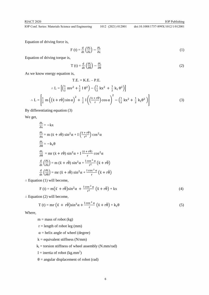
RIACT 2020IOP Conf Series Materials Science and Engineering 1012 (2021) 012001
IOP Publishingdoi1010881757-899X10121012001
11
[7] Atsushi Kakogawa Taiki Nishimura and Shugen Ma 2016 Designing arm length of a screw
drive in-pipe robot for climbing vertically positioned bent pipes Robotica pp 306-327
[8] Atul Gargade Dhanraj Tambuskar and Gajanan Thokal 2013 Modelling and Analysis of Pipe
Inspection Robot International Journal of Emerging Technology and Advanced Engineering pp
120-126
[9] Muhammad Azri Abdul Wahed and Mohd Rizal Arshad 2017 Wall-press Type Pipe Inspection
Robot IEEE 2nd International Conference on Automatic Control and Intelligent Systems
(I2CACIS 2017) Malaysia pp 185-190
[10] Hun-ok Lim and Taku Ohki 2009 Development of Pipe Inspection Robot ICROS-SICE
International Joint Conference Japan pp 5717-5721
[11] R Jain Abhijit Das and A Mukherjee 2019 Design Analysis of Novel Scissor Mechanism for
Pipeline Inspection Robot (PIR) Proceedings of the 4th International Conference of Robotics
Society of India at Indian Institute of Technology Madras India pp 1-6
[12] Ankit Nayak and S Pradhan 2014 Design of a New In-pipe Inspection Robot 12th Global
Congress on Manufacturing and Management (GCMM) pp 2081-2091
[13] Atul Gargade and Shantipal Ohol 2017 Development of Actively Steerable In-pipe Inspection
Robot for Various Sizes Proceedings of the 3rd International Conference of Robotics Society of
India at Indian Institute of Technology Delhi India pp 1-5