Embed Size (px)
Citation preview

COPYRIGHT FIMT 2021 Page 1
Paper Code: BCA 304 L T C
Paper ID: 20304 3 1 4
Paper: Mobile Computing
UNIT - I Introduction to wireless communications: Applications, Short History of Wireless Communications,
Market of Mobile Communications. [T1]
Elementary Knowledge on Wireless Transmission: Frequency of Radio Transmission, Signals,
Antennas, Signal Propagation: Path Loss of Radio Signals, Additional Signal Propagation Effects, Multipath Propagation, Multiplexing: Space Division Multiplexing, Frequency Division Multiplexing,
Time Division Multiplexing, Code Division Multiplexing, Modulation: Amplitude Shift Keying,
Frequency Shift Keying, Phase Shift Keying, Advanced Frequency Shift Keying, Advanced Phase Shift Keying, Multicarrier Modulation, Spread Spectrum: Direct Sequence Spread Spectrum, Frequency
Hopping Spread Spectrum, Cellular Systems. [T1]
[No. of Hrs: 11] UNIT - II Elementary Knowledge on Medium Access Control: Motivation for a specialized MAC, Hidden and
exposed terminals, Near and far terminals, Introduction to SDMA, FDMA, TDMA: Fixed TDM,
Classical Aloha, Slotted Aloha, Carrier sense multiple access, Demand assigned multiple access, PRMA
packet reservation multiple access, Reservation TDMA, Multiple access with collision avoidance, Polling, Inhibit sense multiple access, CDMA, Spread Aloha multiple access, Mobile communications,
Comparison of S/T/F/CDMA. [T1]
Elementary Knowledge on Telecommunications Systems: GSM: Mobile services, System architecture, Radio interface, Protocols, Localization and calling, Handover, Security, New data services, DECT:
System architecture, Protocol architecture.[T1]
Elementary Knowledge on Satellite systems: History, Applications, Basics: GEO, LEO, MEO, Routing, Localization, Handover. [T1] [No. of Hrs: 11]
UNIT - III Mobile Internet: Introducing the Mobile Internet, Services for the mobile Internet, Business
opportunities.[T2]
Implementing WAP Services: WML: WML Variables and Contexts: Variable Substitution, Setting
Variables, Browser Contexts, WML Tasks and Events, WML User Interaction: Problems with Web Interaction, Interaction in WAP, Elements: <input> , <select> ,<option> , <optgroup>, <do> , <anchor> ,
<a> , The tabindex Attribute, WML Timers, WML Decks, Templates, and Cards: Elements: <wml>,
<head>, <access>, <meta> , <card> , <template>, WML Text and Text Formatting, Elements <p>, <br>, Character Formatting, Tables, WML Images: <img> Element, The WBMP Image Format. [T2, T3]
[No. of Hrs: 11]
UNIT - IV
WAP: the Mobile Internet Standard, Making the Internet Mobile: Challenges and Pitfalls, Overview of
the Wireless Application Protocol [T2]
Implementing WAP Services: WML Script: Datatypes, Variables, and Conversions, Operators and Expressions: Operand Conversions, Assignment Operators, Arithmetic Operators, Bitwise Operators,
Shift Operators, Logical Operators, Increment and Decrement Operators, Comparison Operators, Type
Operators, The Conditional Operator, The Comma Operator, Precedence and Associativity, WMLScript Statements: Expressions as Statements, Blocks of Statements, Conditions, Loops, Returning from a
Function, Other Statements, WMLScript Functions: Function Declarations, Function Calls, Calls to
Other Script Units, Calling WMLScript from WML, Standard Libraries, WMLScript Pragmas: The access Pragma, The meta Pragma, Elementry Knowledge on Libraries: Lang , Float , String ,URL ,
WMLBrowser , Dialogs [T2, T3] [No. of Hrs: 11]

COPYRIGHT FIMT 2021 Page 2
UNIT - I
Introduction to wireless communications: -
Wireless operations permit services, such as long-range communications, that are impossible or
impractical to implement with the use of wires. The term is commonly used in the radio transmitters and
receivers, remote controls etc. which use some form of energy to transfer information without the use of
wires. Information is transferred in this manner over both short and long distances.
Applications:-
Mobile telephones: - One of the best-known examples of wireless technology is the mobile phone, also
known as a cellular phone, with more than 4.6 billion mobile cellular subscriptions worldwide as of the
end of 2010. These wireless phones use radio waves to enable their users to make phone calls from many
locations worldwide. They can be used within range of the mobile telephone site used to house the
equipment required to transmit and receive the radio signals from these instruments
Wireless data communications: - Wireless data communications are an essential component of mobile computing. The various available technologies differ in local availability, coverage range and
performance, and in some circumstances, users must be able to employ multiple connection types and switch between them. To simplify the experience for the user, connection manager software can be used,
or a mobile VPN deployed to handle the multiple connections as a secure, single virtual network. Supporting technologies include:
Wi-Fi is a wireless local area network that enables portable computing devices to connect easily to
the Internet., Wi-Fi approaches speeds of some types of wired Ethernet. Wi-Fi has become the de facto standard for access in private homes, within offices, and at public hotspots. Some businesses charge customers a monthly fee for service, while others have begun offering it for free in an effort to increase the sales of their goods.
Cellular data service offers coverage within a range of 10-15 miles from the nearest cell site.
Speeds have increased as technologies have evolved, from earlier technologies such as GSM, CDMA and GPRS, to 3G networks such as W-CDMA, EDGE or CDMA2000.
Mobile Satellite Communications may be used where other wireless connections are unavailable, such as in largely rural areas or remote locations Satellite communications are
especially important for transportation, aviation, maritime and military use.
Wireless energy transfer: - Wireless energy transfer is a process whereby electrical energy is transmitted from a power source to an electrical load that does not have a built-in power source, without the use of interconnecting wires.
Computer interface devices:- Answering the call of customers frustrated with cord clutter, many manufacturers of computer peripherals turned to wireless technology to satisfy their consumer base .Originally these units used bulky, highly limited transceivers to mediate between a computer and a keyboard and mouse; however, more recent generations have used small, high-quality devices, some even incorporating Bluetooth. These systems have become so ubiquitous that some users have begun complaining about a lack of wired peripherals. Wireless devices tend to have a slightly slower response

COPYRIGHT FIMT 2021 Page 3
time than their wired counterparts; however, the gap is decreasing
Short History of Wireless Communications:-
The world's first wireless telephone conversation occurred in 1880, when Alexander Graham Bell and Charles Sumner Tainter invented and patented the photo phone, a telephone that conducted audio
conversations wirelessly over modulated light beams (which are narrow projections of electromagnetic waves). In that distant era, when utilities did not yet exist to provide electricity and lasers had not even
been imagined in science fiction, there were no practical applications for their invention, which was highly limited by the availability of both sunlight and good weather. Similar to free-space optical
communication, the photo phone also required a clear line of sight between its transmitter and its receiver. It would be several decades before the photo phone’s principles found their first practical applications in
military communications and later in fiber-optic communications.
Market of Mobile Communications: - Mobile marketing is marketing on or with a mobile device, such
as a cell phone. Mobile marketing can also be defined as “the use of the mobile medium as a means of
marketing communication”, the “distribution of any kind of promotional or advertising messages to
customer through wireless networks”. More specific definition is the following: “using interactive
wireless media to provide customers with time and location sensitive, personalized information that
promotes goods, services and ideas, thereby generating value for all stakeholders".
Mobile marketing is commonly known as wireless marketing, although viewing advertising on a
computer connected to a home local area network is not considered to be mobile marketing.
SMS marketing
Marketing through cell phones' SMS (Short Message Service) became increasingly popular in the early
2000s in Europe and some parts of Asia when businesses started to collect mobile phone numbers and
send off wanted (or unwanted) content. On average, SMS messages are read within four minutes, making
them highly convertible.
MMS
MMS mobile marketing can contain a timed slideshow of images, text, audio and video. This mobile content is delivered via MMS (Multimedia Message Service). Nearly all new phones produced with a
color screen are capable of sending and receiving standard MMS message. Brands are able to both send (mobile terminated) and receive (mobile originated) rich content through MMS A2P (application-to-
person) mobile networks to mobile subscribers. In some networks, brands are also able to sponsor messages that are sent P2P (person-to-person).

COPYRIGHT FIMT 2021 Page 4
Push notifications
Push Notifications were first introduced to smart phones by Apple with the advent of the iPhone in 2007.
They were later further popularized with the Android operational system, where the notifications are shown on the top of the screen. It has helped application owners to communicate directly with their end
users in a simple and effective way. If not used wisely it can quickly alienate users as it causes interruptions to their current activities on the phone. It can be much cheaper if compared to SMS
Marketing for the long run, but it can become quite expensive on the short run, because the cost involved
in application development. Once the application is downloading and installed provided the feature is not
turned off it is practically free, because it uses internet bandwidth only. SMS and Push Notifications can be part of a well developed Inbound Mobile Marketing Strategy.
In-game mobile marketing
There are essentially four major trends in mobile gaming right now: interactive real-time 3D games,
massive multi-player games and social networking games. This means a trend towards more complex and
more sophisticated, richer game play. On the other side, there are the so-called casual games, i.e. games
that are very simple and very easy to play. Most mobile games today are such casual games and this will
probably stay so for quite a while to come.
Elementary Knowledge on Wireless Transmission:-
Frequency of Radio Transmission:- Radio frequency (RF) is a rate of oscillation in the range of about
3 kHz to 300 GHz, which corresponds to the frequency of radio waves, and the alternating currents which
carry radio signals. RF usually refers to electrical rather than mechanical oscillations; however,
mechanical RF systems do exist (see mechanical filter and RF MEMS).
Although radio frequency is a rate of oscillation, the term "radio frequency" or its abbreviation "RF" are
also used as a synonym for radio - i.e. to describe the use of wireless communication, as opposed to
communication via electric wires.
SIGNAL: - In telephony, a signal is special data that is used to set up or control communication.
In electronics, a signal is an electric current or electromagnetic field used to convey data from one place
to another. The simplest form of signal is a direct current (DC) that is switched on and off; this is the principle by which the early telegraph worked. More complex signals consist of an alternating-current
(AC) or electromagnetic carrier that contains one or more data streams.
COPYRIGHT FIMT 2021 Page 5
Antennas: - Antenna (radio), also known as an aerial, a transducer designed to transmit or receive
electromagnetic (e.g. TV or radio) waves
Television antenna (or TV aerial), is an antenna specifically designed for the reception of broadcast
television signals
Signal Propagation:-
Radio propagation is the behavior of radio waves when they are transmitted, or propagated from one point
on the Earth to another, or into various parts of the atmosphere. As a form of electromagnetic radiation,
like light waves, radio waves are affected by the phenomena of reflection, refraction, diffraction, absorption, polarization and scattering.
Radio propagation is affected by the daily changes of water vapor in the troposphere and ionization in the
upper atmosphere, due to the Sun. Understanding the effects of varying conditions on radio propagation has many practical applications, from choosing frequencies for international shortwave broadcasters, to
designing reliable mobile telephone systems, to radio navigation, to operation of radar systems.
Path Loss of Radio Signals: - The signal path loss is essentially the reduction in power density of an
electromagnetic wave or signal as it propagates through the environment in which it is travelling.
There are many reasons for the radio path loss that may occur:-
• Free space loss: The free space loss occurs as the signal travels through space without any other
effects attenuating the signal it will still diminish as it spreads out. This can be thought of as the
radio communications signal spreading out as an ever increasing sphere. As the signal has to
cover a wider area, conservation of energy tells us that the energy in any given area will reduce as
the area covered becomes larger. • Absorption losses: Absorption losses occur if the radio signal passes into a medium which is not
totally transparent to radio signals. This can be likened to a light signal passing through
transparent glass. • Diffraction: Diffraction losses occur when an object appears in the path. The signal can diffract
around the object, but losses occur. The loss is higher the more rounded the object. Radio signals
tend to diffract better around sharp edges. • Multipath: In a real terrestrial environment, signals will be reflected and they will reach the
receiver via a number of different paths. These signals may add or subtract from each other
depending upon the relative phases of the signals. If the receiver is moved the scenario will
change and the overall received signal will be found vary with position. Mobile receivers (e.g.
cellular telecommunications phones) will be subject to this effect which is known as Rayleigh
fading. • Terrain: The terrain over which signals travel will have a significant effect on the signal.
Obviously hills which obstruct the path will considerably attenuate the signal, often making
reception impossible. Additionally at low frequencies the composition of the earth will have a
marked effect. For example on the Long Wave band, it is found that signals travel best over more
conductive terrain, e.g. sea paths or over areas that are marshy or damp. Dry sandy terrain gives
higher levels of attenuation.
COPYRIGHT FIMT 2021 Page 6
• Buildings and vegetation: For mobile applications, buildings and other obstructions including
vegetation have a marked effect. Not only will buildings reflect radio signals, they will also absorb them. Cellular communications are often significantly impaired within buildings. Trees and foliage can attenuate radio signals, particularly when wet.
• Atmosphere: The atmosphere can affect radio signal paths. At lower frequencies, especially
below 30 - 50MHz, the ionosphere has a significant effect; reflecting (or more correctly refracting) them back to Earth. At frequencies above 50 MHz and more the troposphere has a
major effect, refracting the signals back to earth as a result of changing refractive index. For UHF
broadcast this can extend coverage to approximately a third beyond the horizon.
These reasons represent some of the major elements causing signal path loss for any radio system.
Propagation Effects: - Radio propagation is affected by the daily changes of water vapor in the troposphere and ionization in the upper atmosphere, due to the Sun. Understanding the effects of varying conditions on radio propagation has many practical applications, from choosing frequencies for international shortwave broadcasters, to designing reliable mobile telephone systems, to radio navigation, to operation of radar systems.
Radio propagation is also affected by several other factors determined by its path from point to point. This
path can be a direct line of sight path or an over-the-horizon path aided by refraction in the ionosphere,
which is a region between approximately 60 and 600 km. Factors influencing ionospheric radio signal
propagation can include sporadic-E, spread-F, solar flares, geomagnetic storms, ionospheric layer tilts,
and solar proton events.
Radio waves at different frequencies propagate in different ways. At extra low frequencies (ELF) and
very low frequencies the wavelength is very much larger than the separation between the earth's surface and the D layer of the ionosphere, so electromagnetic waves may propagate in this region as a waveguide.
Indeed, for frequencies below 20 kHz, the wave propagates as a single waveguide mode with a horizontal magnetic field and vertical electric field. The interaction of radio waves with the ionized regions of the
atmosphere makes radio propagation more complex to predict and analyze than in free space. Ionospheric radio propagation has a strong connection to space weather. A sudden ionospheric disturbance or
shortwave fadeout is observed when the x-rays associated with a solar flare ionize the ionospheric D- region. Enhanced ionization in that region increases the absorption of radio signals passing through it.
During the strongest solar x-ray flares, complete absorption of virtually all ionospherically propagated radio signals in the sunlit hemisphere can occur. These solar flares can disrupt HF radio propagation and
affect GPS accuracy.
Multiplexing: - In telecommunications and computer networks, multiplexing (also known as muxing) is a method by which multiple analogue message signals or digital data streams are combined into one
signal over a shared medium. The aim is to share an expensive resource. For example, in telecommunications, several telephone calls may be carried using one wire. Multiplexing originated in
telegraphy in the 1870s, and is now widely applied in communications. In telephony, George Owen Squier is credited with the development of telephone carrier multiplexing in 1910.
COPYRIGHT FIMT 2021 Page 7
Space Division Multiplexing: - Space-division multiple access (SDMA) is a channel access method based on creating parallel spatial pipes next to higher capacity pipes through spatial multiplexing and/or
diversity, by which it is able to offer superior performance in radio multiple access communication
systems. In traditional mobile cellular network systems, the base station has no information on the
position of the mobile units within the cell and radiates the signal in all directions within the cell in order to provide radio coverage. This results in wasting power on transmissions when there are no mobile units
to reach, in addition to causing interference for adjacent cells using the same frequency, so called co-
channel cells. Likewise, in reception, the antenna receives signals coming from all directions including noise and interference signals. By using smart antenna technology and differing spatial locations of
mobile units within the cell, space-division multiple access techniques offer attractive performance
enhancements. The radiation pattern of the base station, both in transmission and reception is adapted to each user to obtain highest gain in the direction of that user. This is often done using phased array
techniques.
In GSM cellular networks, the base station is aware of the distance (but not direction) of a mobile phone by use of a technique called "timing advance" (TA). The base transceiver station (BTS) can determine how distant the mobile station (MS) is by interpreting the reported TA. This information, along with other parameters, can then be used to power down the BTS or MS, if a power control feature is implemented in the network. The power control in either BTS or MS is implemented in most modern networks, especially on the MS, as this ensures a better battery life for the MS. This is also why having a BTS close to the user results in less exposure to electromagnetic radiation.
This is why one may actually be safer to have a BTS close to them as their MS will be powered down as
much as possible. For example, there is more power being transmitted from the MS than what one would receive from the BTS even if they were 6 meters away from a BTS mast. However, this estimation might not consider all the Mobile stations that a particular BTS is supporting with EM radiation at any given time.
In the same manner, 5th generation mobile networks will be focused in utilizing the given position of the MS in relation to BTS in order to focus all MS Radio frequency power to the BTS direction and vice
versa, thus enabling power savings for the Mobile Operator, reducing MS SAR index, reducing the EM field around base stations since beam forming will concentrate power when it will be actually used rather
than spread uniformly around the BTS, reducing health and safety concerns, enhancing spectral efficiency, and decreased MS battery consumption.[
Frequency Division Multiplexing :- In telecommunications, frequency-division multiplexing (FDM) is a
technique by which the total bandwidth available in a communication medium is divided into a series of
non-overlapping frequency sub-bands, each of which is used to carry a separate signal. This allows a
single transmission medium such as the radio spectrum, a cable or optical fiber to be shared by many
signals. The most natural example of frequency-division multiplexing is radio and television
broadcasting, in which multiple radio signals at different frequencies pass through the air at the same
time. Another example is cable television, in which many television channels are carried simultaneously

COPYRIGHT FIMT 2021 Page 8
on a single cable. FDM is also used by telephone systems to transmit multiple telephone calls through high
capacity trunk lines, communications satellites to transmit multiple channels of data on uplink and
downlink radio beams, and broadband DSL modems to transmit large amounts of computer data through
twisted pair telephone lines, among many other uses.
An analogous technique called wavelength division multiplexing is used in fiber optic communication, in
which multiple channels of data are transmitted over a single optical fiber using different wavelengths (frequencies) of light.
Time Division Multiplexing: - Time-division multiplexing (TDM) is a method of transmitting and receiving independent signals over a common signal path by means of synchronized switches at the each
end of the transmission line so that each signal appears on the line only a fraction of time in an alternating pattern. This form of signal multiplexing was developed In telecommunications for telegraphy systems in
the late 1800s, but found its most common application in digital telephony in the second half of the 20th century. Time-division multiplexing is used primarily for digital signals, but may be applied in analog
multiplexing in which two or more signals or bit streams are transferred appearing simultaneously as sub- channels in one communication channel, but are physically taking turns on the channel. The time domain
is divided into several recurrent time slots of fixed length, one for each sub-channel. A sample byte or data block of sub-channel 1 is transmitted during time slot 1, sub-channel 2 during time slot 2, etc. One
TDM frame consists of one time slot per sub-channel plus a synchronization channel and sometimes error correction channel before the synchronization. After the last sub-channel, error correction, and
synchronization, the cycle starts all over again with a new frame, starting with the second sample, byte or data block from sub-channel 1
Code Division Multiplexing: - Code division multiple access (CDMA) is a channel access method used by various radio communication technologies.
CDMA is an example of multiple access, which is where several transmitters can send information
simultaneously over a single communication channel. This allows several users to share a band of
frequencies (see bandwidth). To permit this to be achieved without undue interference between the users
CDMA employs spread-spectrum technology and a special coding scheme (where each transmitter is
assigned a code).
CDMA is used as the access method in many mobile phone standards such as cdmaOne, CDMA2000 (the
3G evolution of cdmaOne), and WCDMA (the 3G standard used by GSM carriers), which are often
referred to as simply CDMA.
modulation :- In electronics and telecommunications, modulation is the process of varying one or more
properties of a periodic waveform, called the carrier signal, with a modulating signal which typically
contains information to be transmitted. This is done in a similar fashion to a musician modulating a tone
(a periodic waveform) from a musical instrument by varying its volume, timing and pitch. The three key
parameters of a periodic waveform are its amplitude ("volume"), its phase ("timing") and its frequency
("pitch"). Any of these properties can be modified in accordance with a low frequency signal to obtain the
modulated signal. Typically a high-frequency sinusoid waveform is used as carrier signal, but a square

COPYRIGHT FIMT 2021 Page 9
wave pulse train may also be used.
In telecommunications, modulation is the process of conveying a message signal, for example a digital bit stream or an analog audio signal, inside another signal that can be physically transmitted. Modulation of a
sine waveform is used to transform a baseband message signal into a pass band signal, for example low- frequency audio signal into a radio-frequency signal (RF signal).
In radio communications, cable TV systems or the public switched telephone network for instance, electrical signals can only be transferred over a limited pass band frequency spectrum, with specific (non-zero) lower and upper cutoff frequencies.
Modulating a sine-wave carrier makes it possible to keep the frequency content of the transferred signal as close as possible to the centre frequency (typically the carrier frequency) of the pass band.
A device that performs modulation is known as a modulator and a device that performs the inverse
operation of modulation is known as a demodulator (sometimes detector or demod). A device that can do both operations is a modem (from "modulator-demodulator").
The aim of digital modulation is to transfer a digital bit stream over an analog band pass channel, for example over the public switched telephone network (where a band pass filter limits the frequency range to between 300 and 3400 Hz), or over a limited radio frequency band.
The aim of analog modulation is to transfer an analog baseband (or low pass) signal, for example an audio signal or TV signal, over an analog band pass channel at a different frequency, for example over a
limited radio frequency band or a cable TV network channel.
Analog and digital modulation facilitate frequency division multiplexing (FDM), where several low pass information signals are transferred simultaneously over the same shared physical medium, using separate pass band channels (several different carrier frequencies).
Amplitude-shift keying :- Amplitude-shift keying (ASK) is a form of amplitude modulation that
represents digital data as variations in the amplitude of a carrier wave.
Any digital modulation scheme uses a finite number of distinct signals to represent digital data. ASK uses a
finite number of amplitudes, each assigned a unique pattern of binary digits. Usually, each amplitude
encodes an equal number of bits. Each pattern of bits forms the symbol that is represented by the
particular amplitude. The demodulator, which is designed specifically for the symbol-set used by the
modulator, determines the amplitude of the received signal and maps it back to the symbol it represents,
thus recovering the original data. Frequency and phase of the carrier are kept constant.
Like AM, ASK is also linear and sensitive to atmospheric noise, distortions, propagation conditions on
COPYRIGHT FIMT 2021 Page 10
different routes in PSTN, etc. Both ASK modulation and demodulation processes are relatively
inexpensive. The ASK technique is also commonly used to transmit digital data over optical fiber. For
LED transmitters, binary 1 is represented by a short pulse of light and binary 0 by the absence of light.
Laser transmitters normally have a fixed "bias" current that causes the device to emit a low light level.
This low level represents binary 0, while a higher-amplitude lightwave represents binary 1.
The simplest and most common form of ASK operates as a switch, using the presence of a carrier wave to
indicate a binary one and its absence to indicate a binary zero. This type of modulation is called on-off keying, and is used at radio frequencies to transmit Morse code (referred to as cont inuous wave
operation),
More sophisticated encoding schemes have been developed which represent data in groups using additional amplitude levels. For instance, a four-level encoding scheme can represent two bits with each shift in amplitude; an eight-level scheme can represent three bits; and so on. These forms of
amplitudeshift keying require a high signal-to-noise ratio for their recovery, as by their nature much of the signal is transmitted at reduced power.
Frequency-shift keying (FSK) is a frequency modulation scheme in which digital information is
transmitted through discrete frequency changes of a carrier wave.
The simplest FSK is binary FSK (BFSK). BFSK uses a pair of discrete frequencies to transmit binary
(0s and 1s) information. With this scheme, the "1" is called the mark frequency and the "0" is called the
space frequency. The time domain of an FSK modulated carrier is illustrated in the figures to the right.
Phase Shift Keying:- Phase-shift keying (PSK) is a digital modulation scheme that conveys data by
changing, or modulating, the phase of a reference signal (the carrier wave).
Any digital modulation scheme uses a finite number of distinct signals to represent digital data. PSK uses
a finite number of phases; each assigned a unique pattern of binary digits. Usually, each phase encodes an
equal number of bits. Each pattern of bits forms the symbol that is represented by the particular phase.
The demodulator, which is designed specifically for the symbol-set used by the modulator, determines the phase of the received signal and maps it back to the symbol it represents, thus recovering the original
data. This requires the receiver to be able to compare the phase of the received signal to a reference signal
— such a system is termed coherent (and referred to as CPSK).
Alternatively, instead of operating with respect to a constant reference wave, the broadcast can operate
with respect to itself. Changes in phase of a single broadcast waveform can be considered the significant
items. In this system, the demodulator determines the changes in the phase of the received signal rather
than the phase (relative to a reference wave) itself. Since this scheme depends on the difference between
successive phases, it is termed differential phase-shift keying (DPSK). DPSK can be significantly
simpler to implement than ordinary PSK since there is no need for the demodulator to have a copy of the
reference signal to determine the exact phase of the received signal (it is a non-coherent scheme). In
exchange, it produces more erroneous demodulation.
COPYRIGHT FIMT 2021 Page 11
Multi-carrier modulation (MCM) is a method of transmitting data by splitting it into several components, and sending each of these components over separate carrier signals. The individual carriers have narrow bandwidth , but the composite signal can have broad bandwidth.
The advantages of MCM include relative immunity to fading caused by transmission over more than
one path at a time (multipath fading), less susceptibility than single-carrier systems to interference caused
by impulse noise, and enhanced immunity to inter-symbol interference. Limitations include difficulty in
synchronizing the carriers under marginal conditions, and a relatively strict requirement that amplification
be linear.
MCM was first used in analog military communications in the 1950s. Recently, MCM has attracted
attention as a means of enhancing the bandwidth of digital communications over media with physical
limitations. The scheme is used in some audio broadcast services. The technology lends itself to digital
television , and is used as a method of obtaining high data speeds in asymmetric digital subscriber line
(ADSL ) systems. MCM is also used in wireless local area networks (WLAN s).
Also see orthogonal frequency-division multiplexing (OFDM ), frequency-division multiplexing (FDM ), and time-division multiplexing (TDM ).
In telecommunication and radio communication, spread-spectrum techniques are methods by which a signal (e.g. an electrical, electromagnetic, or acoustic signal) generated with a particular bandwidth is
deliberately spread in the frequency domain, resulting in a signal with a wider bandwidth. These techniques are used for a variety of reasons, including the establishment of secure communications,
increasing resistance to natural interference, noise and jamming, to prevent detection, and to limit power flux density (e.g. in satellite downlinks).
Spread-spectrum telecommunications:-
This is a technique in which a (telecommunication) signal is transmitted on a bandwidth considerably
larger than the frequency content of the original information. Frequency hopping is a basic modulation
technique used in spread spectrum signal transmission.
Spread-spectrum telecommunications is a signal structuring technique that employs direct sequence,
frequency hopping, or a hybrid of these, which can be used for multiple access and/or multiple functions.
This technique decreases the potential interference to other receivers while achieving privacy. Spread

COPYRIGHT FIMT 2021 Page 12
spectrum generally makes use of a sequential noise-like signal structure to spread the normally
narrowband information signal over a relatively wideband (radio) band of frequencies. The receiver
correlates the received signals to retrieve the original information signal. Originally there were two
motivations: either to resist enemy efforts to jam the communications (anti-jam, or AJ), or to hide the fact
that communication was even taking place, sometimes called low probability of intercept (LPI).
Frequency-hopping spread spectrum (FHSS), direct-sequence spread spectrum (DSSS), time-hopping
spread spectrum (THSS), chirp spread spectrum (CSS), and combinations of these techniques are forms of
spread spectrum. Each of these techniques employs pseudorandom number sequences created using
pseudorandom number generators to determine and control the spreading pattern of the signal across the
allocated bandwidth. Ultra-wideband (UWB) is another modulation technique that accomplishes the same
purpose, based on transmitting short duration pulses.
In communications, direct-sequence spread spectrum (DSSS) is a modulation technique. As with other spread spectrum technologies, the transmitted signal takes up more bandwidth than the information signal
that modulates the carrier or broadcast frequency. The name 'spread spectrum' comes from the fact that
the carrier signals occur over the full bandwidth (spectrum) of a device's transmitting frequency.
DSSS phase-modulates a sine wave pseudo randomly with a continuous string of pseudo noise (PN) code
symbols called "chips", each of which has a much shorter duration than an information bit. That is, each
information bit is modulated by a sequence of much faster chips. Therefore, the chip rate is much higher than the information signal bit rate.
1. DSSS uses a signal structure in which the sequence of chips produced by the transmitter is
already known by the receiver. The receiver can then use the same PN sequence to counteract the effect of the PN sequence on the received signal in order to reconstruct the information signal.
Frequency-hopping spread spectrum (FHSS) is a method of transmitting radio signals by rapidly
switching a carrier among many frequency channels, using a pseudorandom sequence known to both
transmitter and receiver. It is utilized as a multiple access method in the frequency-hopping code
division multiple access (FH-CDMA) scheme.
Spread-spectrum
A spread-spectrum transmission offers three main advantages over a fixed-frequency transmission:
COPYRIGHT FIMT 2021 Page 13
1. Spread-spectrum signals are highly resistant to narrowband interference. The process of re- collecting a spread signal spreads out the interfering signal, causing it to recede into the background.
2. Spread-spectrum signals are difficult to intercept. A spread-spectrum signal may simply appear as an increase in the background noise to a narrowband receiver. An eavesdropper may have
difficulty intercepting a transmission in real time if the pseudorandom sequence is not known.
3. Spread-spectrum transmissions can share a frequency band with many types of conventional
transmissions with minimal interference. The spread-spectrum signals add minimal noise to the narrow-frequency communications, and vice versa. As a result, bandwidth can be utilized more
efficiently.
Military use:-
Spread-spectrum signals are highly resistant to deliberate jamming, unless the adversary has knowledge
of the spreading characteristics. Military radios use cryptographic techniques to generate the channel sequence under the control of a secret Transmission Security Key (TRANSEC) that the sender and
receiver share in advance.
By itself, frequency hopping provides only limited protection against eavesdropping and jamming. There
is a simple algorithm that effectively discovers the sequence of frequencies. To get around this weakness
most modern military frequency hopping radios employ separate encryption devices such as the KY-57.
U.S. military radios that use frequency hopping include the JTIDS/MIDS family, HAVE QUICK and
SINCGARS.
Cellular Systems:-
The covering area of an operator is divided into cells. A cell corresponds to the covering area of one
transmitter or a small collection of transmitters. The size of a cell is determined by the transmitter's power.
The concept of cellular systems is the use of low power transmitters in order to enable the efficient reuse of the frequencies. In fact, if the transmitters used are very powerful, the frequencies cannot be reused for hundreds of kilometers as they are limited to the covering area of the transmitter.
The frequency band allocated to a cellular mobile radio system is distributed over a group of cells and this
distribution is repeated in all the domain of an operator. The whole number of radio channels available can then be used in each group of cells that form the covering area of an operator. Frequencies used in a
cell are reused several cells away. The distance between the cells using the same frequency must be sufficient to avoid interference. The frequency reuse will increase considerably the capacity in number of
users.
In order to work properly, a cellular system must verify the following two main conditions:

COPYRIGHT FIMT 2021 Page 14
• The power level of a transmitter within a single cell must be limited in order to reduce the
interference with the transmitters of neighboring cells. The interference will not produce any
damage to the system if a distance of about 2.5-3 times the diameter of a cell is reserved between transmitters. This also depends on the performance of the receiver's filters.
UNIT-II
Elementary Knowledge on Medium Access Control:-
In the seven-layer OSI model of computer networking, media access control (MAC) data communication
protocol is a sub layer of the data link layer, which itself is layer 2. The MAC sub layer provides
addressing and channel access control mechanisms that make it possible for several terminals or network
nodes to communicate within a multiple access network that incorporates a shared medium, e.g. Ethernet.
The hardware that implements the MAC is referred to as a medium access controller.
The MAC sub layer acts as an interface between the logical link control (LLC) sub layer and the
network's physical layer. The MAC layer emulates a full-duplex logical communication channel in a
multi-point network. This channel may provide uncast, multicast or broadcast communication service.
Motivation for a specialized (MAC):-
The Media Access Control (MAC) data communication protocol sub-layer, also known as the Medium
Access Control, is a sub layer of the Data Link Layer specified in the seven-layer OSI model (layer 2).
The hardware that implements the MAC is referred to as a Medium Access Controller. The MAC
sublayer acts as an interface between the Logical Link Control (LLC) sub layer and the network's
physical layer. The MAC layer emulates a full-duplex logical communication channel in a multi-point
network. This channel may provide uni cast, multicast or broadcast communication service.

COPYRIGHT FIMT 2021 Page 15
LLC and MAC sub layers
Motivation for a specialized MAC
One of the most commonly used MAC schemes for wired networks is carrier sense multiple access with
collision detection (CSMA/CD). In this scheme, a sender senses the medium (a wire or coaxial cable) to
see if it is free. If the medium is busy, the sender waits until it is free. If the medium is free, the sender
starts transmitting data and continues to listen into the medium. If the sender detects a collision while
sending, it stops at once and sends a jamming signal. But this scheme doest work well with wireless
networks. The problems are:
• Signal strength decreases proportional to the square of the distance
• The sender would apply CS and CD, but the collisions happen at the receiver
• It might be a case that a sender cannot “hear” the collision, i.e., CD does not work
• Furthermore, CS might not work, if for e.g., a terminal is “hidden”
Hidden and Exposed Terminals
Consider the scenario with three mobile phones as shown below. The transmission range of A reaches B,
but not C (the detection range does not reach C either). The transmission range of C reaches B, but not A.
Finally, the transmission range of B reaches A and C, i.e., A cannot detect C and vice versa.

COPYRIGHT FIMT 2021 Page 16
Hidden terminals
• A sends to B, C cannot hear A
• C wants to send to B, C senses a “free” medium (CS fails) and starts transmitting
• Collision at B occurs, A cannot detect this collision (CD fails) and continues with its transmission
to B
• A is “hidden” from C and vice versa
Exposed terminals
• B sends to A, C wants to send to another terminal (not A or B) outside the range
• C senses the carrier and detects that the carrier is busy.
• C postpones its transmission until it detects the medium as being idle again
• but A is outside radio range of C, waiting is not necessary
• C is “exposed” to B
Hidden terminals cause collisions, where as Exposed terminals causes unnecessary delay.
Near and far terminals
Consider the situation shown below. A and B are both sending with the same transmission power.
• Signal strength decreases proportional to the square of the distance
• So, B’s signal drowns out A’s signal making C unable to receive A’s transmission

COPYRIGHT FIMT 2021 Page 17
• If C is an arbiter for sending rights, B drown out A’s signal on the physical layer making C
unable to hear out A.
The near/far effect is a severe problem of wireless networks using CDM. All signals should arrive at the
receiver with more or less the same strength for which Precise power control is to be implemented.
SDMA
Space Division Multiple Access (SDMA) is used for allocating a separated space to users in wireless
networks. A typical application involves assigning an optimal base station to a mobile phone user. The
mobile phone may receive several base stations with different quality. A MAC algorithm could now
decide which base station is best, taking into account which frequencies (FDM), time slots (TDM) or code
(CDM) are still available. The basis for the SDMA algorithm is formed by cells and sectorized antennas
which constitute the infrastructure implementing space division multiplexing (SDM). SDM has the
unique advantage of not requiring any multiplexing equipment. It is usually combined with other
multiplexing techniques to better utilize the individual physical channels.
FDMA
Frequency division multiplexing (FDM) describes schemes to subdivide the frequency dimension into
several non-overlapping frequency bands.

COPYRIGHT FIMT 2021 Page 18
Frequency Division Multiple Access is a method employed to permit several users to transmit
simultaneously on one satellite transponder by assigning a specific frequency within the channel to each
user. Each conversation gets its own, unique, radio channel. The channels are relatively narrow, usually
30 KHz or less and are defined as either transmit or receive channels. A full duplex conversation requires
a transmit & receive channel pair. FDM is often used for simultaneous access to the medium by base
station and mobile station in cellular networks establishing a duplex channel. A scheme called frequency
division duplexing (FDD) in which the two directions, mobile station to base station and vice versa are
now separated using different frequencies.
FDM for multiple access and duplex
The two frequencies are also known as uplink, i.e., from mobile station to base station or from ground
control to satellite, and as downlink, i.e., from base station to mobile station or from satellite to ground
control. The basic frequency allocation scheme for GSM is fixed and regulated by national authorities.
All uplinks use the band between 890.2 and 915 MHz, all downlinks use 935.2 to 960 MHz. According to
FDMA, the base station, shown on the right side, allocates a certain frequency for up- and downlink to
establish a duplex channel with a mobile phone. Up- and downlink have a fixed relation. If the uplink
frequency is fu = 890 MHz + n·0.2 MHz, the downlink frequency is fd = fu + 45 MHz, i.e., fd = 935
MHz + n·0.2 MHz for a certain channel n.

COPYRIGHT FIMT 2021 Page 19
The base station selects the channel. Each channel (uplink and
downlink) has a bandwidth of 200 kHz.
This scheme also has disadvantages. While radio stations broadcast 24 hours a day, mobile
communication typically takes place for only a few minutes at a time. Assigning a separate frequency for
each possible communication scenario would be a tremendous waste of (scarce) frequency resources.
Additionally, the fixed assignment of a frequency to a sender makes the scheme very inflexible and limits
the number of senders.
TDMA
A more flexible multiplexing scheme for typical mobile communications is time division multiplexing
(TDM). Compared to FDMA, time division multiple access (TDMA) offers a much more flexible

COPYRIGHT FIMT 2021 Page 20
scheme, which comprises all technologies that allocate certain time slots for communication. Now
synchronization between sender and receiver has to be achieved in the time domain. Again this can be
done by using a fixed pattern similar to FDMA techniques, i.e., allocating a certain time slot for a
channel, or by using a dynamic allocation scheme.
Listening to different frequencies at the same time is quite difficult, but listening to many channels
separated in time at the same frequency is simple. Fixed schemes do not need identification, but are not as
flexible considering varying bandwidth requirements.
Fixed TDM
The simplest algorithm for using TDM is allocating time slots for channels in a fixed pattern. This results
in a fixed bandwidth and is the typical solution for wireless phone systems. MAC is quite simple, as the
only crucial factor is accessing the reserved time slot at the right moment. If this synchronization is
assured, each mobile station knows its turn and no interference will happen. The fixed pattern can be
assigned by the base station, where competition between different mobile stations that want to access the
medium is solved.

COPYRIGHT FIMT 2021 Page 21
The above figure shows how these fixed TDM patterns are used to implement multiple access and a
duplex channel between a base station and mobile station. Assigning different slots for uplink and
downlink using the same frequency is called time division duplex (TDD). As shown in the figure, the
base station uses one out of 12 slots for the downlink, whereas the mobile station uses one out of 12
different slots for the uplink. Uplink and downlink are separated in time. Up to 12 different mobile
stations can use the same frequency without interference using this scheme. Each connection is allotted its
own up- and downlink pair. This general scheme still wastes a lot of bandwidth. It is too static, too
inflexible for data communication. In this case, connectionless, demand-oriented TDMA schemes can be
used
Classical Aloha
In this scheme, TDM is applied without controlling medium access. Here each station can access the
medium at any time as shown below:
This is a random access scheme, without a central arbiter controlling access and without coordination
among the stations. If two or more stations access the medium at the same time, a collision occurs and the
transmitted data is destroyed. Resolving this problem is left to higher layers (e.g., retransmission of data).
The simple Aloha works fine for a light load and does not require any complicated access mechanisms.
Slotted Aloha
The first refinement of the classical Aloha scheme is provided by the introduction of time slots (slotted
Aloha). In this case, all senders have to be synchronized, transmission can only start at the beginning of a
time slot as shown below.

COPYRIGHT FIMT 2021 Page 22
The introduction of slots raises the throughput from 18 per cent to 36 per cent, i.e., slotting doubles the
throughput. Both basic Aloha principles occur in many systems that implement distributed access to a
medium. Aloha systems work perfectly well under a light load, but they cannot give any hard
transmission guarantees, such as maximum delay before accessing the medium or minimum throughput.
Carrier sense multiple access
One improvement to the basic Aloha is sensing the carrier before accessing the medium. Sensing the
carrier and accessing the medium only if the carrier is idle decreases the probability of a collision. But, as
already mentioned in the introduction, hidden terminals cannot be detected, so, if a hidden terminal
transmits at the same time as another sender, a collision might occur at the receiver. This basic scheme is
still used in most wireless LANs. The different versions of CSMA are:
• 1-persistent CSMA: Stations sense the channel and listens if its busy and transmit immediately,
when the channel becomes idle. It’s called 1-persistent CSMA because the host transmits with a
probability of 1 whenever it finds the channel idle.
• non-persistent CSMA: stations sense the carrier and start sending immediately if the medium is
idle. If the medium is busy, the station pauses a random amount of time before sensing the
medium again and repeating this pattern.
• p-persistent CSMA: systems nodes also sense the medium, but only transmit with a probability
of p, with the station deferring to the next slot with the probability 1-p, i.e., access is slotted in
addition
CSMA with collision avoidance (CSMA/CA) is one of the access schemes used in wireless LANs
following the standard IEEE 802.11. Here sensing the carrier is combined with a back-off scheme in case
of a busy medium to achieve some fairness among competing stations.

COPYRIGHT FIMT 2021 Page 23
Demand assigned multiple access
Channel efficiency for Aloha is 18% and for slotted Aloha is 36%. It can be increased to 80% by
implementing reservation mechanisms and combinations with some (fixed) TDM patterns. These schemes
typically have a reservation period followed by a transmission period. During the reservation period,
stations can reserve future slots in the transmission period. While, depending on the scheme, collisions
may occur during the reservation period, the transmission period can then be accessed without collision.
One basic scheme is demand assigned multiple access (DAMA) also called reservation Aloha, a
scheme typical for satellite systems. It increases the amount of users in a pool of satellite channels that are
available for use by any station in a network. It is assumed that not all users will need simultaneous access
to the same communication channels. So that a call can be established, DAMA assigns a pair of available
channels based on requests issued from a user. Once the call is completed, the channels are returned to the
pool for an assignment to another call. Since the resources of the satellite are being used only in
proportion to the occupied channels for the time in which they are being held, it is a perfect environment
for voice traffic and data traffic in batch mode.
It has two modes as shown below.

COPYRIGHT FIMT 2021 Page 24
During a contention phase following the slotted Aloha scheme; all stations can try to reserve future slots.
Collisions during the reservation phase do not destroy data transmission, but only the short requests for
data transmission. If successful, a time slot in the future is reserved, and no other station is allowed to
transmit during this slot. Therefore, the satellite collects all successful requests (the others are destroyed)
and sends back a reservation list indicating access rights for future slots. All ground stations have to obey
this list. To maintain the fixed TDM pattern of reservation and transmission, the stations have to be
synchronized from time to time. DAMA is an explicit reservation scheme. Each transmission slot has to
be reserved explicitly.
PRMA packet reservation multiple access
It is a kind of implicit reservation scheme where, slots can be reserved implicitly. A certain number of
slots form a frame. The frame is repeated in time i.e., a fixed TDM pattern is applied. A base station,
which could be a satellite, now broadcasts the status of each slot to all mobile stations. All stations
receiving this vector will then know which slot is occupied and which slot is currently free.
The base station broadcasts the reservation status ‘ACDABA-F’ to all stations, here A to F. This means
that slots one to six and eight are occupied, but slot seven is free in the following transmission. All
stations wishing to transmit can now compete for this free slot in Aloha fashion. The already occupied
slots are not touched. In the example shown, more than one station wants to access this slot, so a collision
occurs. The base station returns the reservation status ‘ACDABA-F’, indicating that the reservation of slot
seven failed (still indicated as free) and that nothing has changed for the other slots. Again, stations can
compete for this slot. Additionally, station D has stopped sending in slot three and station F in slot eight.
This is noticed by the base station after the second frame. Before the third frame starts, the base station
indicates that slots three and eight are now idle. Station F has succeeded in reserving slot seven as also
indicated by the base station.

COPYRIGHT FIMT 2021 Page 25
As soon as a station has succeeded with a reservation, all future slots are implicitly reserved for this station.
This ensures transmission with a guaranteed data rate. The slotted aloha scheme is used for idle slots only; data
transmission is not destroyed by collision.
Reservation TDMA
In a fixed TDM scheme N mini-slots followed by N·k data-slots form a frame that is repeated. Each station is
allotted its own mini-slot and can use it to reserve up to k data-slots.
This guarantees each station a certain bandwidth and a fixed delay. Other stations can now send data in unused
data-slots as shown. Using these free slots can be based on a simple round-robin scheme or can be uncoordinated
using an Aloha scheme. This scheme allows for the combination of, e.g., isochronous traffic with fixed bitrates
and best-effort traffic without any guarantees.
CDMA
Code division multiple access systems apply codes with certain characteristics to the transmission to separate
different users in code space and to enable access to a shared medium without interference.

COPYRIGHT FIMT 2021 Page 26
All terminals send on the same frequency probably at the same time and can use the whole bandwidth of the
transmission channel. Each sender has a unique random number, the sender XORs the signal with this random
number. The receiver can “tune” into this signal if it knows the pseudo random number, tuning is done via a
correlation function
Disadvantages:
• higher complexity of a receiver (receiver cannot just listen into the medium and start receiving if
there is a signal)
• all signals should have the same strength at a receiver
Advantages:
• all terminals can use the same frequency, no planning needed
• huge code space (e.g. 232) compared to frequency space
• interferences (e.g. white noise) is not coded
• forward error correction and encryption can be easily integrated
COPYRIGHT FIMT 2021 Page 27
Comparison SDMA/TDMA/FDMA/CDMA
Multiple access with collision avoidance:-
Multiple Access with Collision Avoidance (MACA) is a slotted media access control protocol used in
wireless LAN data transmission to avoid collisions caused by the hidden station problem and to simplify
exposed station problem.
The basic idea of MACA is a wireless network node makes an announcement before it sends the data
frame to inform other nodes to keep silent. When a node wants to transmit, it sends a signal called
Request-To-Send (RTS) with the length of the data frame to send. If the receiver allows the transmission,
it replies the sender a signal called Clear-To-Send (CTS) with the length of the frame that is about to receive.
Meanwhile, a node that hears RTS should remain silent to avoid conflict with CTS; a node that hears CTS should
keep silent until the data transmission is complete.
WLAN data transmission collisions may still occur, and the MACA for Wireless (MACAW) is
introduced to extend the function of MACA.
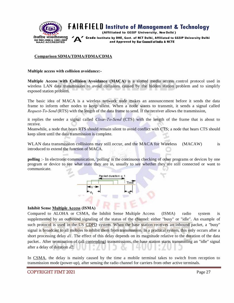
polling :- In electronic communication, 'polling' is the continuous checking of other programs or devices by one program or device to see what state they are in, usually to see whether they are still connected or want to communicate.
Inhibit Sense Multiple Access (ISMA)
Compared to ALOHA or CSMA, the Inhibit Sense Multiple Access (ISMA) radio system is
supplemented by an outbound signaling of the status of the channel: either "busy" or "idle". An example of
such protocol is used in the US CDPD system. When the base station receives an inbound packet, a "busy"
signal is broadcast to all mobiles to inhibit them from transmission. In a practical system, this only occurs after a
short processing delay d1. The effect of this delay depends on its magnitude relative to the duration of the data
packet.. After termination of (all contending) transmissions, the base station starts transmitting an "idle" signal
after a delay of duration d2.
In CSMA, the delay is mainly caused by the time a mobile terminal takes to switch from reception to
transmission mode (power-up), after sensing the radio channel for carriers from other active terminals.

COPYRIGHT FIMT 2021 Page 28
The busy period is defined as the period during which the base station broadcasts a busy signal plus the
preceding signaling delay d1. For memory less Poisson arrivals, the duration of the idle period, i.e., the
time interval starting at the release of the channel until the first packet arrival is exponentially distributed
with mean I = 1/G.
The busy period is the time interval between the first arrival of a packet until the moment that the channel
becomes idle. During the initial period d1 of the busy period the outbound channel thus still reports an idle inbound channel. The duration of the busy period is at least 1 + d2, but may be longer if a collision is caused by a
packet arrival in during the inhibit delay. Moreover, persistent terminals, that sense a busy signal, may start to transmit immediately after the channel becomes idle. In such cases the busy period has a duration longer than
two (or more) units of time.
No persistent ISMA
For no persistent CSMA and ISMA, rescheduling (with random back-off time) always occurs if the channel
is busy at the instant of sensing. So, if a packet arrives at a nonpersistent terminal when the base station
transmits a "busy" signal, the attempt is considered to have failed. If the feedback channel (or in CSMA the
channel sensing mechanism) is imperfect, a transmission may erroneously be started in the period. The packet is
rescheduled for later transmission.
1 - Persistent ISMA
Figure: Description of terminal behavior in 1-persistent ISMA/CSMA random access network
p - Persistent ISMA
Mobile communications:-
When you are away from the office, you may need to keep in touch with things in various ways: by
telephone or email, or by using your appointments diary.
COPYRIGHT FIMT 2021 Page 29
There are now many devices on the market designed to enable communications while on the move: the mobile
phone, the Smartphone, tablet devices, the Personal Digital Assistant (PDA), and Wi-Fi, or 3G cards for use in
your laptop computer, to name but a few. On top of that, the combinations of features that can be used together
can be very confusing.
You need to consider a number of things before purchasing a mobile device and/or service. What
facilities do you need? Do you need to check your St Andrews email account when you are away from
your office? Would you like to view and keep your University diary up to date in your office, or
remotely? Do you need web or Internet access? Would you like GPS and satellite navigation facilities?
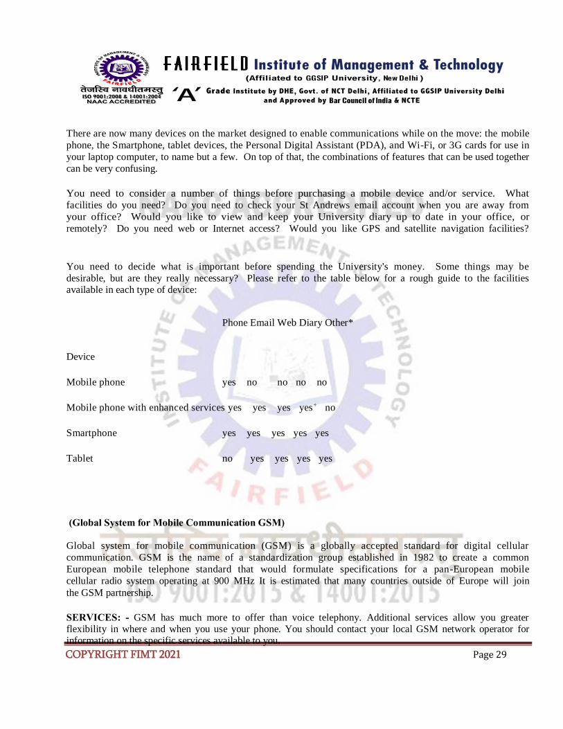
You need to decide what is important before spending the University's money. Some things may be
desirable, but are they really necessary? Please refer to the table below for a rough guide to the facilities available in each type of device:
Phone Email Web Diary Other*
Device
Mobile phone yes no no no no
Mobile phone with enhanced services yes yes yes yes+ no
Smartphone yes yes yes yes yes
Tablet no yes yes yes yes
(Global System for Mobile Communication GSM)
Global system for mobile communication (GSM) is a globally accepted standard for digital cellular
communication. GSM is the name of a standardization group established in 1982 to create a common
European mobile telephone standard that would formulate specifications for a pan-European mobile
cellular radio system operating at 900 MHz It is estimated that many countries outside of Europe will join
the GSM partnership.
SERVICES: - GSM has much more to offer than voice telephony. Additional services allow you greater flexibility in where and when you use your phone. You should contact your local GSM network operator for information on the specific services available to you.

COPYRIGHT FIMT 2021 Page 30
But there are three basic types of services offered through GSM which you can ask for:
• Telephony (also referred to as Teleservice) Services
• Data (also referred to as bearer services) Services.
• Supplementary Services
Teleservices or Telephony Services:
A Teleservice utilizes the capabilities of a Bearer Service to transport data, defining which capabilities are required and how they should be set up.
Voice Calls:
The most basic Teleservice supported by GSM is telephony. This includes Full-rate speech at 13 Kbps and emergency calls, where the nearest emergency- service provider is notified by dialing three digits. A very basic example of emergency service is 911 services available in USA.
Videotext and Facsimile:
Another group of tele services includes Videotext access, Teletex transmission, Facsimile alternate speech and
facsimile Group 3, Automatic facsimile Group 3 etc.
Short Text Messages:
SMS (Short Messaging Service) service is a text messaging which allow you to send and receive text
messages on your GSM Mobile phone. Services available from many of the world's GSM networks today
- in addition to simple user generated text message services - include news, sport, financial, language and location based services, as well as many early examples of mobile commerce such as stocks and share prices, mobile banking facilities and leisure booking services.
Bearer Services or Data Services
Using your GSM phone to receive and send data is the essential building block leading to widespread mobile
Internet access and mobile data transfer. GSM currently has a data transfer rate of 9.6k. New developments
that will push up data transfer rates for GSM users are HSCSD (high speed circuit switched data) and GPRS (general packet radio service) are now available.
Supplementary Services
Supplementary services are provided on top of teleservices or bearer services, and include features such as
caller identification, call forwarding, call waiting, multi-party conversations, and barring of outgoing
(international) calls, among others. A brief description of supplementary services is given here:
COPYRIGHT FIMT 2021 Page 31
• Multiparty Service or conferencing: The multiparty service allows a mobile subscriber to establish a multiparty conversation. that is, a simultaneous conversation between three or more subscribers to setup a conference call. This service is only applicable to normal telephony.
• Call Waiting: This service allows a mobile subscriber to be notified of an incoming call during a conversation. The subscriber can answer, reject, or ignore the incoming call. Call waiting is applicable to all GSM telecommunications services using a circuit-switched connection.
• Call Hold: This service allows a subscriber to put an incoming call on hold and then resume this
call. The call hold service is only applicable to normal telephony.
• Call Forwarding: The Call Forwarding Supplementary Service is used to divert calls from the
original recipient to another number, and is normally set up by the subscriber himself. It can be
used by the subscriber to divert calls from the Mobile Station when the subscriber is not
available, and so to ensure that calls are not lost. A typical scenario would be a salesperson turns
off his mobile phone during a meeting with customers, but does not with to lose potential sales
leads while he is unavailable.
• Call Barring: The concept of barring certain types of calls might seem to be a supplementary
disservice rather than service. However, there are times when the subscriber is not the actual user
of the Mobile Station, and as a consequence may wish to limit its functionality, so as to limit the
charges incurred. Alternatively, if the subscriber and user are one and the same, the Call Barring
may be useful to stop calls being routed to international destinations when they are routed. The
reason for this is because it is expected that the roaming subscriber will pay the charges incurred for
international re-routing of calls. So, GSM devised some flexible services that enable the subscriber to
conditionally bar calls.
• Number Identification: There are following supplementary services related to number
identification:
o Calling Line Identification Presentation: This service deals with the presentation of the
calling party's telephone number. The concept is for this number to be presented, at
the
start of the phone ringing, so that the called person can determine who is ringing prior
to
answering. The person subscribing to the service receives the telephone number of the
calling party. o Calling Line Identification Restriction: A person not wishing their number to be presented to others subscribes to this service. In the normal course of event, the restriction service overrides the presentation service.
o Connected Line Identification Presentation: This service is provided to give the
calling party the telephone number of the person to whom they are connected. This
may
seem strange since the person making the call should know the number they dialled,
but
there are situations (such as forwardings) where the number connected is not the
number
dialled. The person subscribing to the service is the calling party.
COPYRIGHT FIMT 2021 Page 32
o Connected Line Identification Restriction: There are times when the person called does not wish to have their number presented and so they would subscribe to this person. Normally, this overrides the presentation service.
o Malicious Call Identification: The malicious call identification service was provided to combat the spread of obscene or annoying calls. The victim should subscribe to this service, and then they could cause known malicious calls to be identified in the GSM network, using a simple command. This identified number could then be passed to the
appropriate authority for action. The definition for this service is not stable.
• Advice of Charge (AoC): This service was designed to give the subscriber an indication of the
cost of the services as they are used. Furthermore, those Service Providers who wish to offer
rental services to subscribers without their own Subscriber Identity Module (SIM) can also utilize
this service in a slightly different form. AoC for data calls is provided on the basis of time measurements.
• Closed User Groups (CUGs): This service is provided on GSM to enable groups of subscribers
to only call each other. This type of services is being offered with special discount and is limited only to those members who wish to talk to each other.
• Unstructured supplementary services data (USSD): This allows operator-defined individual
services.
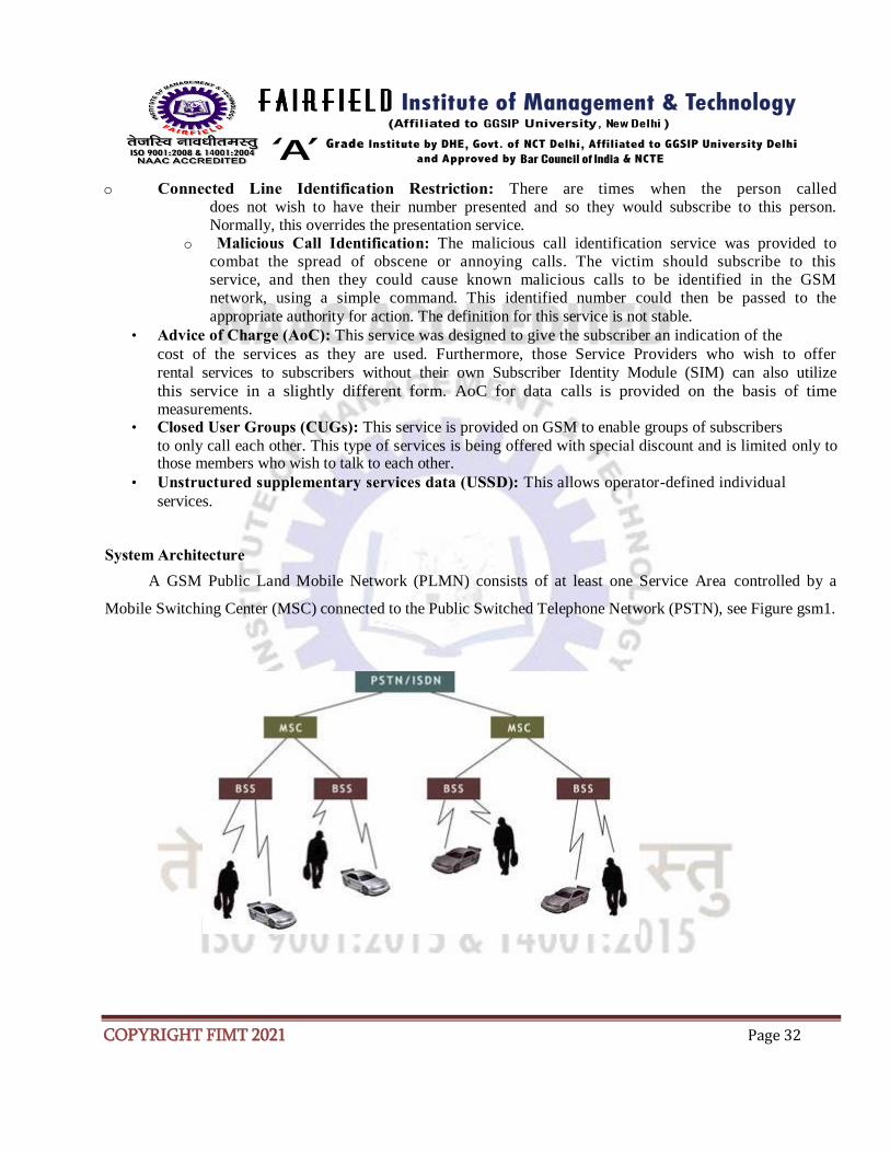
System Architecture
A GSM Public Land Mobile Network (PLMN) consists of at least one Service Area controlled by a
Mobile Switching Center (MSC) connected to the Public Switched Telephone Network (PSTN), see Figure gsm1.

COPYRIGHT FIMT 2021 Page 33
Figure gsm1. The architecture of a GSM Public Land Mobile Network (PLMN)
A Base Station Subsystem (BSS) consists of
• a Base Station Controller (BSC)
• at least one radio saccess point or Base Transceiver Station (BTS) for Mobile Stations (MS), which are
mobile phones or other handheld devices (for example PDA computers) with phone interface.
A BTS, with its aerial and associated radio frequency components, is the actual transmission and reception
component. A Network Cell is the area of radio coverage by one BTS. One or more BTSs are in turn managed by a
BSC. A network cell cluster covered by one or several BSSs can be managed as a Location Area (LA). All these
BSSs must however be controlled by a single MSC. In Figure gsm2 is shown three LAs of 3, 4 and 4 cells
respectively with a MS moving across cell and LA boundaries.
Figure gsm2. A MS moving across cell and LA boundaries.
3 LAs consisting of 4 and 5 cells respectively are shown.
COPYRIGHT FIMT 2021 Page 34
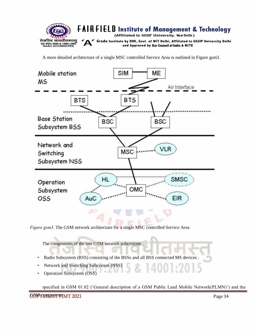
A more detailed architecture of a single MSC controlled Service Area is outlined in Figure gsm3.
Figure gsm3. The GSM network architecture for a single MSC controlled Service Area
The components of the tree GSM network subsystems
• Radio Subsystem (RSS) consisting of the BSSs and all BSS connected MS devices .
• Network and Switching Subsystem (NSS)
• Operation Subsystem (OSS)
specified in GSM 01.02 (‘General description of a GSM Public Land Mobile Network(PLMN)’) and the
GSM components

COPYRIGHT FIMT 2021 Page 35
ME = Mobile Equipment
BTS = Base Receiving Station
BSC = Base Station Controller
MSC = Mobile Switching Center
VLR = Visitor Location Register
OMC = Operation and Maintenance
Center AuC = Authentication Center
HLR = Home Location Register
EIR = Equipment Identity Register
SMSC = Short Message Service
Centre are shown in Figure gsm3.
A MSC is also through a Gateway MSC (GMSC) connected to other MSCs and to the Public Switched
Telephone Network (PSTN) with the Integrated Services Digital Network (ISDN) option. The Inter -
Working Function (IWF) of GMSC connects the circuit switched data paths of a GSM network with the
PSTN/ISDN. A GMSC is usually integrated in an MSC, see Figure gsm.
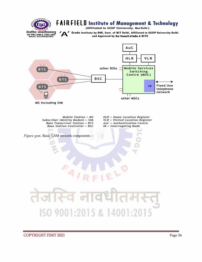
COPYRIGHT FIMT 2021 Page 36
Figure gsm. Basic GSM network components

COPYRIGHT FIMT 2021 Page 37
Network and Switching Subsystem (NSS)
NSS consists of the Mobile Switching Center (MSC) and the Visitor Location Register (VLR). A MSC
manages multiple BSSs and is responsible for
• setting up, managing and shutting down connections,
• handling call charges
• supervising supplementary services, such as call forwarding, call blocking and conference calling.
VLR contains information about all MSs currently within range of the associated MSC. This information is
needed for routing a call to a particular MS (mobile telephone) via the proper BSS and radio cell. The VLR also
maintains a list of MSs belonging to subscribers of other GSM networks. Such subscribers have logged or roamed
into the network of the associated MSC. The area covered by a MSC is actually called a MSC/VLR Service Area ,
which can consist of several LAs as is shown in Figure gsm5.
Figure gsm5. A MSC/VLR Service Area

COPYRIGHT FIMT 2021 Page 38
Operation Subsystem (OSS)
The OSS consists of
• the Operation and Maintenance Center (OMC)
• the Authentication Center (AuC),
• the Home Location Register (HLR)
• the Equipment Identity Register (EIR).
OMC is responsible for
• regular network operation
• subscriber administration
• call billing.
AuC is the security component on the network side. AuC generates and manages all cryptographic keys and
algorithms needed for network operation, especially for authentication of the MSs (i.e., the SIMs). HLR contains all
of the subscriber data as well as the localization data for each of the MS. EIR contains essential data, such as the
serial numbers of all MSs represented in the network. OSS also controls the Short Message Service Centre (SMSC)
for transmission of SMS messages. SMSC need information in HLR for the routing of SMS messages.
GSM Network Areas
In GSM, there is a strong distinction between subscribers, which are identified by their SIM, and the
hardware they use for making phone calls and data communication calls. For identification both entities before and
during GSM service allocation, several identification numbers exist and are stored in HLR, VLR and EIR.
The following identification numbers are stored in the HLR:
• International Mobile Subscriber Identity (IMSI), a permanent ID assigned to each GSM network
subscriber.
• International Mobile Subscriber ISDN Number (MSISDN), the ISDN number (phone number)
permanently assigned to each GSM subscriber.

COPYRIGHT FIMT 2021 Page 39
• Mobile Station Roaming Number (MSRN), a temporary ISDN number of a subscriber. This number is
assigned by the local VLR each time, the subscriber enters its MSC/VLR area. The MSRN is then sent to
the HLR and to the GMSC.
• The address of current VLR and MSC (if available), an address of the area the subscriber is currently in.
• Local Mobile Subscriber Identity (if available), a short ID temporarily assigned to an active subscriber by
an VLR and sent to the HLR.
The following identification numbers are stored temporarily at the VLR associated with the MSC which is
currently controlling an active MS:
• IMSI
• MSISDN
• MSRN
• Location Area Identity (LAI), the ID of the Location Area (LA), in which subscriber is or has been
connected to a GSM network.
• Temporary Mobile Subscriber Identity (TMSI), temporarily assigned to an active MS in order to
prevent the IMSI from being transmitted too often over the radio interface. The TMSI is periodically
changed during a call.
Equipment Identity Register (EIR) is a database for mobile equipment information of all subscribers. In this
database, three lists (white, black and gray) store identification
numbers, which are unique to all mobile terminals. The white list contains allowed terminals, the black list contains
unallowed terminals (e.g. stolen or lost), and the gray contains terminals with known bugs.
GSM Network Areas
The area covered by one GSM operator is called the PLMN Service Area, which can consist of several
MSC/VLR Service Areas as i shown in Figure gsm6. A typical PLMN Service Area is thus the area of a country, a
state, or a region. A GSM Network Area is thus a hierarchy with the levels
• PLMN Service Area
• MSC/VLR Service Area, see Figure gsm5
• Location Area (LA), see Figure gsm2
• Network Cell.

COPYRIGHT FIMT 2021 Page 40
Figure gsm6. A PLMN Service Area for a GSM operator
GSM: Radio interface
One of the main objectives of GSM is roaming. Thus, to allow for interoperability between MNs stations
and disparate networks of the radio interface must be standardised. Spectrum efficiency depends on
aspects of the radio interface and transmission, such as system capacity or techniques used to optimize
SIR and frequency reuse. It thus, becomes clear that the specification of the radio interface can influence
the spectrum efficiency.
Frequency allocation
Two frequency bands, of 25 Mhz each, are allocated for the GSM system:
• 890-915 Mhz for the uplink (MN to BTS).
• 935-960 Mhz for the downlink (BTS to M).
However, for reasons related to the military as well as the existence of past analog systes (that use part of
the two frequency bands), not all the countries can use the whole GSM frequency bands.
Medium access
GSM employs a mix of Frequency Division Multiple Access (FDMA) and Time Division Multiple Access (TDMA), combined with frequency hopping.
Using FDMA, a frequency is assigned to each user. So for large number of users in a FDMA system, the
larger the number of required frequencies. The limited available radio spectrum and the fact that a user
will not free its assigned frequency until he does not need it anymore, reasons about scalability problems in an FDMA system.

COPYRIGHT FIMT 2021 Page 41
TDMA allows several users to share the same channel. Each subscriber multiplexes the shared channel, scheduling their frame for transmission. Usually TDMA is used with an FDMA structure.
In GSM, a 25 Mhz frequency band is divided, using a FDMA scheme, into 124 carrier frequencies with a
200khz spacing. Normally a 25 Mhz frequency band can provide 125 carrier frequencies; however, the first carrier frequency is used as a guard-band between GSM and other services working on lower freq. band. Each carrier is time-divided using a TDMA scheme. This scheme splits a 200khz channel, into 8 bursts. A burst is the unit of time in a TDMA system, and it lasts approximately 0.577ms. Thus a TDMA
lasts 4.615ms. Each burst is assigned to a single user.
Channel structure
A channel maps to the recurrence of one burst every frame. It is defined by its frequency and the
position of its corresponding burst within a TDMA frame. In GSM there are two types of channels:
• traffic channels used for speech and data.
• control channels used for network management messages and channel maintenance tasks.
Traffic channels (TCH)
Full-rate traffic channels (TCH/F) are defined using a group of 26 TDMA frames called a 26-
Multiframe. The 26-Multiframe lasts 120 ms. In this frame group traffic channels for the downlink and
uplink are separated by 3 bursts. That implies, the mobiles will not need to transmit and receive at the
same time which simplifies considerably the electronics of the system.
The frames that form the 26-Multiframe structure have different functions:
• 24 frames are reserved to traffic. • 1 frame is used for the Slow Associated Control Channel (SACCH).
• The last frame is unused. It allows the MN to perform other functions, such as measuring the signal strength of neighboring cells.
Half-rate traffic channels (TCH/H), which double the capacity of the system, are also grouped in a 26- Multiframe but the internal structure is different.
Control channels
According to their functions, 4 different classes of control channels are defined:
Broadcast channels (BCH)
The BCH channels are used, by BTS to provide the MN with synchronization information from the network. 3 different types of BCHs can be distinguished:

COPYRIGHT FIMT 2021 Page 42
•
Broadcast Control Channel (BCCH): gives to the MN the parameters needed to identify and access the network.
• Synchronization Channel (SCH): gives the MN the training symbol sequence to demodulate the information transmitted by BTS.
• Frequency-Correction Channel (FCCH): provides the MN with the frequency reference of the
system for the purposes of synchronization.
Common Control Channels (CCCH)
The CCCH channels help to establish the call from the mobile station or the network. These are:
• Paging Channel (PCH): used to alert the MN of an incoming call.
• Random Access Channel (RACH): used by the MN to request network access.
• Access Grant Channel (AGCH): used, by the BTS, to inform the MN about the channel it should use. This channel is the answer of a BTS to a RACH request from the MN.
Dedicated Control Channels (DCCH)
The DCCH channels are used for message exchange between several mobiles or a mobile and the network. These are:
• Standalone Dedicated Control Channel (SDCCH): used to exchange signaling in the downlink
and uplink. • Slow Associated Control Channel (SACCH): used for channel maintenance and control.
Associated Control Channels (ACCH)
Fast Associated Control Channels (FACCH) replaces all or part of a traffic channel when urgent
signaling must be transmitted. The FACCH channels carry the same signaling as SDCCH channels.
Burst structure
Four different types of bursts can be distinguished in GSM:
• Frequency-correction, used on the FCCH. It has the same length as the normal one but a
different structure.
• Synchronization burst used on the SCH. It has the same length as the normal one but a different structure.
• Random access used on the RACH and is shorter than the normal burst.
• Normal burst used to carry speech or data information. It lasts approximately 0.577 ms and has a length of 156.25 bits. Its structure is presented below.

COPYRIGHT FIMT 2021 Page 43
Structure of the 26-Multiframe, the TDMA frame and the normal burst
The tail bits (T) are a group of 3 bits set to zero and placed at the beginning and the end of a burst. They
cover the periods of ramping up and down of the mobile's power.
The coded data bits corresponds to two groups, of 57 bits each, containing signaling or user data.
The stealing flags (S) indicate, to the receiver, whether the data bits are data or signaling traffic.
The training sequence has a length of 26 bits. It synchronizes the receiver, thus masking out multipath propagation effects.
The guard period (GP), with a length of 8.25 bits, is used to avoid a possible overlap of two mobiles
during the ramping time.
Elementary Knowledge on Satellite systems:
The Merriam-Webster dictionary defines a satellite as a celestial body orbiting another of larger size or a
manufactured object or vehicle intended to orbit the earth, the moon, or another celestial body.
Today's satellite communications can trace their origins all the way back to the Moon. A project named
communication moon relay was a telecommunication project carried out by the United States Navy. Its
objective was to develop a secure and reliable method of wireless communication by using the Moon as a
natural communications satellite.

COPYRIGHT FIMT 2021 Page 44
The first artificial satellite used solely to further advances in global communications was a balloon named
Echo 1. Echo 1 was the world's first artificial communications satellite capable of relaying signals to other points on Earth. It soared 1,000 miles (1,609 km) above the planet after its Aug. 12, 1960 launch, yet
relied on humanity's oldest flight technology — ballooning. Launched by NASA, Echo 1 was a giant metallic balloon 100 feet (30 meters) across. The world's first inflatable satellite — or "satelloon," as they
were informally known — helped lay the foundation of today's satellite communications. The idea behind a communications satellite is simple: Send data up into space and beam it back down to another spot on
the globe. Echo 1 accomplished this by essentially serving as an enormous mirror 10 stories tall that could be used to bounce communications signals off of.
The first American satellite to relay communications was project scope in 1958, which used a tape
recorder to store & forward voice messages. It was used to send a Christmas greeting to the world from
U.S. President Dwight D. Eisenhower. NASA launched the Echo satellite in 1960; the 100-foot (30 m)
aluminised PET film balloon served as a passive reflector for radio communications. Courier 1B, built by
Philco, also launched in 1960, was the world's first active repeater satellite.
Applications:-
1) Telephone
2) Digital cinema
3) Radio
4) Military
5) Internet access
BASICS:-
Satellite Systems can be classified based upon their orbits as low earth orbit, medium earth orbit &
geostationary earth orbit systems. Geostationary is also the highest earth orbit and hence, also provides
the greatest visibility using only a few satellites. The coverage region of a satellite is called its footprint.
This is the region from which the satellite is visible. Three geostationary satellite footprints ensure
complete coverage of the earth as shown:

COPYRIGHT FIMT 2021 Page 45
Hence, there is permanent or 24 hour visibility of geostationary satellites without the need of handoffs.
While LEO & MEO satellites do not have 24 hour visibility as the satellites have smaller footprints since
they are closer to the earth (low satellite height). Hence, a larger number of satellites are needed to cover
the earth. Also, since each satellite has a small footprint, handoffs are also required between satellites.
Major differences between LEO, MEO & GEO satellite systems:
Parameter LEO MEO GEO
Satellite Height 500-1500 km 5000-12000 km 35,800 km
Orbital Period 10-40 minutes 2-8 hours 24 hours
Number of Satellites 40-80 8-20 3
Satellite Life Short Long Long
Number of Handoffs High Low Least(none)
Gateway Cost Very Expensive Expensive Cheap
Propagation Loss Least High Highest

COPYRIGHT FIMT 2021 Page 46
Routing:-
Routing is the process of selecting paths in a network along which to send network traffic. Routing is
performed for many kinds of networks, including the telephone network (circuit switching), electronic data networks (such as the Internet), and transportation networks. This article is concerned primarily with
routing in electronic data networks using packet switching technology.
In packet switching networks, routing directs packet forwarding (the transit of logically addressed packets
from their source toward their ultimate destination) through intermediate nodes. Intermediate nodes are
typically network hardware devices such as routers, bridges, gateways, firewalls, or switches. General-
purpose computers can also forward packets and perform routing, though they are not specialized
hardware and may suffer from limited performance. The routing process usually directs forwarding on the
basis of routing tables which maintain a record of the routes to various network destinations. Thus,
constructing routing tables, which are held in the router's memory, is very important for efficient routing.
Most routing algorithms use only one network path at a time. Multipath routing techniques enable the use
of multiple alternative paths.

COPYRIGHT FIMT 2021 Page 47
UNIT-III
Introduction - the Mobile Internet
Forget first generation WAP
We call it the ‘Mobile Internet’ these days to differentiate between the latest and the first Versions of the
protocol used to deliver a web experience on the mobile phone (i.e. WAP or Wireless Application Protocol). WAP 1.0 was black & white and very slow whereas the latest generation of WAP (2.0) is based on the same XHTML standards (Extensible Hypertext Mark-up Language) used by PC browsers such as IE and Firefox and supports mobile internet sites and applications.
WAP 2.0 gives a superb, interactive online experience in full color
For the non-technical, WAP 2.0 gives a mobile internet experience that uses the full colour range of the
handset screen, allows forms (text boxes) to be completed and submitted, enable slinks to be followed and applies a set of standards that should ensure all handsets render a high quality mobile internet website (or
WAP site).Since 2003 most mobiles have adopted WAP2.0 for rendering mobile internet sites and in the last two years a consensus has emerged that mobile internet sites should be tall and thin like the image to
the left. Do I need two internet sites?
The beauty of the new standards is that, when written properly, one website should load correctly on a PC
as well as old and new mobile phones and PDAs. This means you need only one website- a single URL
or web address -and should have to maintain only one set of content. This does however assume some fore thought has been employed during design. Of course what you see on different devices will look
different since screen orientations and sizes vary, even though one set of code is delivering multiple
versions of the site. Take a look at the Incentivized website on your PC and mobile for example. When
you open the page our web server determines.
Implementing WAP Services:-
A significant difference between WML and HTML is that WML supports variables. WML variables
contain strings, and these strings can be inserted into the body text of the WML document or into the
values of certain attributes. The values of variables can be changed under the control of the WML itself and also from within WML Script functions.
Variable Substitution
Variables can be inserted (or substituted) into the body text or an attribute value in one of three ways:
$name
$(name) $(name:conversion)
Setting Variables
You now know just about everything there is to know about actually using WML variables, but one thing you don't yet know is how to put useful values into the variables in the first place!
Actually, there are three ways. The most common is through the use of the various user interface elements, which are described. Variables can also be set from WMLScript, as explained. The third way is with the <setvar> element.
COPYRIGHT FIMT 2021 Page 48
Browser Contexts
The browser context in WML is the set of all variables currently set, together with the history stack (the list of all the cards the user has recently visited).
The context is emptied (all variables are unset, and the stack is emptied) when a card is displayed with the
new context attribute set to true for more on cards and their attributes.
WML Tasks and Events
In the last chapter, you learned about variables in WML, something not found in HTML. This chapter covers two further parts of WML—tasks and events—that have no real equivalent in HTML. (In some cases you can use JavaScript to achieve similar effects.)
WML User Interaction
The previous two chapters described some of the features found in WML that don't exist in HTML. This chapter covers the features that WML provides to receive input from the user, and most of these are much more powerful than their equivalents in HTML.
The main reason for this extra power is that WML has variables. In HTML, you can have controls such as
pulldown menus or text input fields, but you can use these in only limited ways: in an HTML form, which
allows you to collect a number of controls and send their results to a server for processing, or with Java or JavaScript, which are complete programming languages built into the web browser.
Problems with Web Interaction
Using HTML forms for this purpose suffers from one major problem: the processing has to be done on
the server. The client displays the controls, collects their results, packages them, and sends them to the server, but that's it. Apart from some simple constraints such as the maximum length of the text in an
input box, you can't even check the input for validity before sending it off. This results in a lot of extra network connections, slowing things down a lot, even on a fast Internet link. Imagine how slow all those
extra network connections are on a much slower link, as WAP has to contend with.
Using Java or JavaScript to collect the input does allow local processing, but they come complete with their own sets of problems. For a start, they both require a lot more from the browser: most older browsers have either no support for these or very limited or buggy support, which makes it harder to write pages that work across all browsers. Most text-only browsers don't support these at all. (Yes, some people do still use text-only browsers.)
Another, subtler problem with the Web's way of doing these things is that there are multiple ways to declare the controls. Suppose you want to display a text input box. Using a form, you can use something like:
<INPUT TYPE="TEXT" NAME="wibble">
Using JavaScript with the HTML, possibly:
<INPUT TYPE="TEXT" NAME="wibble" ONCHANGE="wibble_chg( );">

COPYRIGHT FIMT 2021 Page 49
If using Java applets, something like:[1]
[1] It isn't completely fair to compare Java with HTML here, since Java is a full-featured programming language, and HTML is just a markup language. But since Java is often used to implement this sort of thing on web pages, it's appropriate to mention it here.
TextField wibble = new TextField ( );
add (wibble);
Each of these fragments has to be referenced in a completely different way from within the HTML page that forms the skeleton. Furthermore, the same control has to be added to the page in three different ways, even though they are all drawn in the same way by the browser, and the user interacts with each in the same way. This makes it hard to change the action of a control once it has been implemented. It requires rewriting everything related to that control, and probably restructuring the whole page as well.
Interaction in WAP
For comparison, here is how the same text input box is described in WML, where its result is sent directly
to the server:
<input name="wibble"/>
Here, its result is passed to some WMLScript to check it for validity before passing it to the server:
<input name="wibble"/>
Here, it's displayed to the user in another card for confirmation purposes, without any server transactions
involved:
<input name="wibble"/>
These three examples are identical because the same control is always written in the same way in WML. Doing it this way works because none of the controls ever perform any direct action. They are instead linked to the lower-level layers of WML, such as variables and tasks.
For example, in the previous <input> element, the only effect of the user entering some text into the box is that the variable wibble is set to a new value. The browser doesn't directly send the text to the server or call any scripts: it's up to you to use the value of this variable at some point.
Elements:-
The <input> Element
Let's start our exploration of WML's mechanisms for user interaction with the <input> element, since
we've just seen it in action.
This element is used whenever the user needs to enter a string or some other piece of text. Usually, this
should be kept as short as possible, since many WAP users use cell phone keypads to enter these. Entering the letter S on a computer keyboard is easy, but this requires four keypresses on most cell phones. Symbols are even worse: with the exception of a few, such as. and +, symbols are very time- consuming to enter.

COPYRIGHT FIMT 2021 Page 50
The <input> element can also be used to enter passwords or other sensitive information. In these cases, the element can be configured to not display the text as it's being entered. (In the case of cell phones, most
display each character for a short time but then replace it with a * or other symbol.)
This element is also used for entering numbers. In cases like this, where the range of characters is restricted, it's possible to set a format for the string, which may speed up input. To do so, set the format to
allow only digits; a cell phone knows that the keys don't need to cycle through all the letters before
offering a digit (the digits are accessed with a single keypress instead of four or more).
This element (as with all user interaction elements) may be put anywhere in normal paragraph text (namely, inside a <p> element). It takes nine attributes, most of which are optional.
The <select> Element
The other high-level control that WML provides is one allowing selection from a list of items. This replaces many different types of control, such as scrolling selectable lists, pulldown menus, and lists of checkboxes.
In its simplest form, the <select> element provides an iname attribute giving a WML variable name.
Inside the <select> is a list of <option> elements. Selecting an option sets the iname variable to the index
of that item within the <select>, starting from 1. For example:
<select iname="animal">
<option>Lizard</option>
<option>Spider</option>
<option>Squid</option>
</select>
Selecting Lizard sets animal to 1, selecting Spider sets it to 2, and selecting Squid sets it to 3.
In a slightly more complex form, the <select> element has a name attribute rather than iname, and a list of
<option> elements, each of which has a value attribute. Selecting one of these options sets the name variable to the contents of the option's value attribute. For example, a list allowing the user to select a
London airport can be written as:
<select name="airport">
<option value="LHR">London Heathrow</option>
<option value="LGW">London Gatwick</option>
<option value="STN">London Stansted</option>
<option value="LCY">London City</option>
<option value="LTN">London Luton</option>
</select>
The <option> Element
While on the subject of the <select> element, it's time for a closer look at the <option> element that is so
vital to it. You've already seen the two most common ways to use this element (with or without a value),
but it's also possible to bind a task to an option, so that the task is performed when the user selects the option (or deselects it, for a multiple-selection list).
COPYRIGHT FIMT 2021 Page 51
This task is bound to the onpick event. It can be bound either with a conventional <onevent> binding, or for simple <go> tasks it can be specified with the onpick attribute on the <option> tag itself.
The <optgroup> Element
WAP doesn't define how the <select> element is displayed. It has been implemented in many different ways, including using pulldown menus, scrolling lists, and lines of checkboxes on PDA-type devices and several different types of menus on cell phones.
With a small screen, it isn't always possible to display all the available options at the same time. There are several ways to get around this problem: if the options are displayed normally in the text of the page, as
with checkboxes for example, then the normal facilities for scrolling the page will do. Many cell phones simply display the currently selected option; activating this for editing changes the screen to a different display with the options. When the editing is complete, the display changes back to the card.
The purpose of the <optgroup> element is to divide a long list of options into several sections. Different
browsers may use this information in different ways: many simply ignore it (particularly those running on
devices with large screens). Others may display the title of the group as part of the option display but not
do anything more with it. Some may use the group title as the name of a submenu, with the contents of
the group in that submenu. The information is a hint, nothing more.
The <optgroup> element takes only one attribute:
The <do> Element
The <input> and <select> elements provide high-level user controls, but sometimes all you want is a
simple button or menu item. In these cases, the <do> element is exactly what you need.
A <do> element is simply a way to specify some arbitrary type of control for the browser to make
available to the user. This can be rendered as a graphical button (as many PDA browsers do), as an item
in a menu (as most cell phone browsers do), or as just about anything the user can know about and
interact with. This can even include things such as voice commands for a hands-off WAP browser (in a
car, for example).
A <do> element contains nothing but the task to be performed when the element is activated
The <anchor> Element
While the <do> element is useful, it isn't always what you want. Many cell phone browsers put all the
<do> items in a card in a single menu, which means you can't guarantee it will appear where you want it
to. Sometimes you want to make some of the text into an HTML-style link, rather than have a separate
<do> control next to it. For example, if you have a menu of other pages available, you want the items in
the menu to display in the correct order
The <a> Element
If you've done much work with HTML, the <anchor> element may seem like a lot of typing. Sure, it's
more flexible than HTML's <A> tag, but it seems much nicer to simply type:
<A HREF="somewhere">linked text</A>
COPYRIGHT FIMT 2021 Page 52
than it is to type:
<anchor><go href="somewhere"/>linked text</anchor>
Fear not: the designers of WML also recognized this fact and provided WML with the <a> element. (The
name must be a lowercase a.) It's a useful shorthand for this simple case of the <anchor> element, which also has the benefit of looking familiar to HTML developers. It takes two attributes:
title (optional variable string)
This has exactly the same effect as the title attribute on the <anchor> element. It provides an optional title for the element, which some browsers may use in displaying it. The same caveats
apply: it's wise to keep the length to at most six characters, and the browser is free to ignore the
attribute (as indeed most do).
href (required variable URL)
Specifies the URL to go to when the link is activated.
For example, the element:
<a title="Next" href="page17.wml">Next Page</a>
is exactly equivalent to:
<anchor title="Next">
<go href="page17.wml"/> Next Page
</anchor>
The form using the <a> element is also more efficient than the form using <anchor>, as there is less to
transmit to the browser. Try to use the <a> form wherever possible.
The tabindex Attribute
Some browsers can cycle through <input> and <select> in a card using some sort of TAB key or similar
control. Normally, the order in which this happens is chosen by the browser (usually the order in which the elements are specified in the card). The tabindex attribute allows this order to be changed for some or
all of the elements in a card.
Not all browsers support this feature, as it doesn't fit into all of the user interfaces. If this feature is supported, the browser sorts all the <input> and <select> elements with a tabindex specified in ascending
order. Pressing the TAB key (or whatever normally cycles through such elements) then selects these
elements in this order. Any elements in the card without a tabindex specified are selected last.

COPYRIGHT FIMT 2021 Page 53
Example 4.4 shows how this attribute can be used. The user is asked for a normal postal address. Both the county and nation fields have no tabindex: nation because it has a default, and county because it's usually unnecessary to give a county or state if the postal code is correct. The <do> element at the end calls a WMLScript function to check that the values are acceptable (for example, if no postal code is given, a county is required).
Example 4.4. Use of the tabindex Attribute
<?xml version="1.0"?>
<!DOCTYPE wml PUBLIC "-//WAPFORUM//DTD WML 1.1//EN"
"http://www.wapforum.org/DTD/wml_1.1.xml">
<wml>
<card title="Enter address">
<p>Street:
<input name="street" tabindex="1"/></p>
<p>Town/City:
<input name="town" tabindex="2"/></p>
<p>County/State/Province: <input name="county"/></p>
<p>Postal/Zip Code:
<input name="code" tabindex="3"/></p>
<p>Nation:
<input name="nation" value="uk"/></p>
<do type="accept" label="OK"> <go href="address.wmlsc#check( )"/>
</do>
</card>
</wml>
WML Timers
The previous chapters described how to interact with users in WML. Sometimes, however, you may want something to happen without the user explicitly having to activate a control.
To take a common example, suppose you want to display a company logo when the user connects to your
WAP service. On a web page, you'd keep the image for the logo on screen the whole time, but WAP devices have limited screen sizes, and you can't afford to waste the space.
COPYRIGHT FIMT 2021 Page 54
WML Decks, Templates, and Cards
Now that you've seen some of the interesting things you can put into a deck, it's time to revisit those very first WML elements we saw back. You can see them in more detail in the light of what you now know about WML; particularly events and the <do> element

COPYRIGHT FIMT 2021 Page 55
A Simple WML Example
<?xml version="1.0"?> <!DOCTYPE wml PUBLIC
"-//WAPFORUM//DTD WML 1.1//EN"
"http://www.wapforum.org/DTD/wml_1.1.xml">
<wml>
<card title="First WML Example">
<p>Hello, World!</p> </card>
</wml>
Elements:-
The <wml> Element
The <wml> element serves a purpose much like the <HTML> element does for HTML pages: it encloses
the entirety of the deck. Effectively, a WML deck consists of a single <wml> element. It doesn't take any
attributes
The <head> Element
The <head> element in WML is similar to the <HEAD> element in HTML: it marks a place for metainformation about the document to be stored. Meta-information is information about the document
itself, rather than its content. If present, the <head> element must be the first thing inside the <wml>
element. It doesn't take any attributes.
The <access> Element
The <access> element provides a simple form of access control for a deck. This allows a deck to specify
that only certain other decks may link to it (these decks are known as referring URLs). Since this control is
performed in the browser, not the server, there is no real security in this mechanism, and hence it's
probably of limited use. There may be no more than one <access> element in a deck, and it must be the
first thing inside the <head> element.
The <meta> Element
The <meta> element places an item of arbitrary meta-information in a WML deck. This item is structured
as a property name and its value. You can put any number of <meta> elements into the <head> element.
This can add keywords for indexing purposes, store hints about the content of the deck, and store any
other information. No standard properties have yet been defined for WML, but conventions will develop,
just as they did with HTML.
The <card> Element
As you saw back in the <card> element encloses a WML card within a deck. In addition, text and
graphics enclosed within <p> elements, it may also contain a number of event bindings and a timer
The <template> Element

COPYRIGHT FIMT 2021 Page 56
The <template> element provides an interesting WML feature not found in HTML. When you write a deck containing several cards, you may find that parts of the structure are common to all the cards. For
example, it's fairly typical for each card to have a "back" control and a "home" control. These controls are normally implemented as <do> elements. It would be convenient to specify these common elements once per deck rather than once per card, and that is just what the <template> element allows.
It doesn't stop there, though. Remember all those card events from .Wouldn't it be easier to set up
bindings for all the events just once for the whole deck? That would certainly save wear and tear on your
fingers (or at least your cut-and-paste keys), and since WAP is supposed to be optimized for low
bandwidth, it's a waste of time to have to send all that duplicated information. As you might have
guessed, the <template> element allows this, too
WML Text and Text Formatting
By this point, you have seen how to create all sorts of interactive applications in WML and how to use
variables, tasks, and events to do things that would require serious server-side processing in HTML.
Now that there aren't any exciting new features to cover, it's time to go back to simple text and see what can be done with it to make it more interesting. This is an area where WML is seriously lacking in comparison to HTML, which provides all sorts of features for changing the size, style, typeface, and color of text, as well as powerful support for tables.
The <p> Element
As you saw back in, the <p> element marks a paragraph of text in a WML card. All body text, user controls (such as <input> and <select> elements), and images must appear within a <p> element. Most browsers ignore any that fall outside a <p>, but some actually reject the deck and refuse to display it. The one exception to this rule is the <do> element, which may appear either inside or outside a <p>. (It's actually regarded as better style to leave it outside the <p>.)
Normally, the <p> element is used without attributes, which results in the text in the paragraph being
leftaligned and wrapped into lines to fit on the screen. It can also take two attributes to control how the text
is presented, assuming of course that the browser is able (and willing) to display text with different alignments or to display non wrapped text.
The <br> Element
The <br> element is one of the simplest in WML. It takes no attributes and is always specified as an empty-element tag, <br/>. It marks a line break in a paragraph of text: when the browser encounters a <br/>, it starts a new line.
You may ask what the difference is between using a <br/> to break lines:
Character Formatting
The support for character formatting in WML is quite limited compared to HTML. There is no support for
specifying the color or typeface of the text, size changes are limited to "bigger" or "smaller," and there's
no guarantee that any of these choices will be honored anyway.
Support is provided through seven elements. None take any attributes, and their effect applies to all the
text they enclose. The browser is free to ignore any or all these attributes if it chooses or if its screen
display can't cope with them.

COPYRIGHT FIMT 2021 Page 57
Tables
Tables are one of the worst-supported features in WML, at least in browsers available at the time of
writing. The reason for this is that displaying tables properly (as laid down in the WAP specifications)
often requires a lot of screen space, which is at a premium on devices such as cell phones. For example, at
least one browser currently available displays each cell of a table on a new line, with lines of * characters
to mark the places where rows should have started.
WML also doesn't allow user interface elements to appear in tables, except for anchored text (using the <a> or <anchor> elements). This makes it easier for those browsers that do support tables. You are,
however, allowed images, text-style changes, and even line breaks.
WML Images
This chapter is the last one in this book dealing with WML, before we get into WMLScript. Therefore, it's
finally time to get around to the subject of images in WML.
Why have I put this topic so late in the book? Because images should not be your major concern when
writing WML. Most modern web pages rely heavily on images, so most books on HTML cover images
quite early. When writing WML, however, you should remember that most WAP browsers are limited in
terms of their image support.
The <img> Element
Images are put into a WML page using the <img> element. If you're familiar with HTML, you'll recognize this tag, and it's indeed used in a similar way. Keep in mind that some browsers lay out images inline with text, while others place images on separate lines.
The WBMP Image Format
You may have noticed that all the examples of the <img> element in this book have used image names
ending with .wbmp. This is a special image format used in WAP. In fact, it's the only image format most browsers support. All WAP browsers that support images must support WBMP, so it's the safest choice if
you want to include images in your WML.
WBMP stands for wireless bitmap, and it's a simple image format. Forget things like color, or animation, or even compression. (Image formats such as GIF and JPEG are the two most common on web pages; they compress the data to make the files smaller and faster to download.) WBMP files store only two things about the image: its size and a block of pixels, each of which is either black or white. There may be future versions with more features, but at the moment black and white is all there is.

COPYRIGHT FIMT 2021 Page 58
UNIT - IV
Implementing WAP Services:-
Introduction to WML Script
Now that you have reached this point in the book, you should have a good idea of the things that can be
done with WML alone: static page layouts and simple user interaction. Until now, the only way you could have any complicated interactions would be with some sort of dynamic content on the server.
Although WML provides variables, tasks, and events to make interaction much cleaner and easier, there are some tasks that can't be done in WML alone. If data must be checked for validity, for instance to
make sure that a phone number really looks like a phone number or to check that a credit card number has
the right number of digits, this checking has to be done by something outside WML.
WML Script Data types, Variables, and Conversions
WML Script is a weekly typed language. This means you never specify the data type of a variable or the return type of a function. All expressions have a type internally, but WML Script itself converts values back and forth between the different types as required, so that you don't have to.
For example, the value 1234 is an integer, but if you pass it to the String .length ( ) library function, which
expects a string, it's implicitly converted to the string "1234", the length of which is 4.
WML Script Operators and Expressions
Now that you know about WML Script's data types, it's time to see how they can be linked with operators to
form expressions.
If you know such languages as C or Java, the operators in this section will be familiar to you. Some of
them have subtle differences, however, which are usually linked to WML Script's dynamic typing. These differences will be pointed out as we encounter them.
Operand Conversions
Some operators can take values of more than one type. For example, the * operator for multiplication can operate on either integers or floating-point numbers. WML Script also defines which conversions are done in these cases:
• Operators that always take the same type of operands simply convert the arguments to those types. If the conversion fails, the result of the operation is invalid.
• Operators that take operands of any type simply use the values as they are. No conversion is
performed because none is needed.
Assignment Operators
Having expressions isn't much use unless you can assign them to variables, and assigning to variables is the purpose of the assignment operators. The left side of any assignment operator
must be the variable to assign.

COPYRIGHT FIMT 2021 Page 59
The most common assignment operator is the simplest, which simply assigns an expression to a variable. It's represented by =.
Arithmetic Operators
WML Script provides all the normal arithmetic operators. The syntax for these is exactly the same as in C
or Java.
The simplest two arithmetic operators are unary plus, represented by +, and unary minus, represented by - . Unary plus simply converts the value to a number,[1] and unary minus converts the value to a number,
then negates it (subtracts it from zero).
If it's already a number, no conversion is required. The phrase "convert to a number" really means "convert to a number if it isn't one already."
Bitwise Operators
In addition to the normal arithmetic operators, WML Script provides four operators for performing Boolean arithmetic on the bits that make up integers. These operators all operate only on integers, so if any operand can't be converted to an integer, the result of the operation is invalid.
Bitwise complement (also called bitwise not) flips every bit in its argument. (Every 0 bit becomes 1, and every 1 bit becomes 0.) It's represented by the ~ operator.
Shift Operators
As well as these operators to change individual bits, WML Script also provides shift operators, which allow you to move all the bits in an integer left or right. Because of the way integers are represented, these can be used to multiply or divide integers by a power of two.
Shift right has two operators, >> and >>>. The difference between these two is that >> handles negative
numbers properly, so you can always use it to do division by powers of two. On the other hand, >>> treats
all numbers as unsigned, even though all integers in WML Script are signed, and because of this it doesn't
work as you'd expect for negative numbers. It's most often used, like the &, |, and ^ operators, when you
use an integer just to store 32 separate bits, rather than a standard integer.
Logical Operators
The bitwise operators are all useful in their place, but far more often you just want a simple Boolean and
or or operator that converts its operands to Boolean values rather than integers.
These operators (called logical operators to distinguish them from the bitwise operators) also perform short-circuit evaluation. This means that they evaluate their left operand first, and if that is enough to tell the final result, the right operand isn't evaluated.

COPYRIGHT FIMT 2021 Page 60
Increment and Decrement Operators
WML Script provides four operators as a conveniently short form for the common task of adding or
subtracting one from a variable.
Comparison Operators
WML Script provides the standard six comparison operators: equal to represented by ==, not equal to
represented by !=, less than represented by <, less than or equal to represented by <=, greater than represented by >, and greater than or equal to represented by >=.
Expression the equal to comparison is the classic gotcha of C-like languages. You need to be careful to write == rather than = if you mean the "equal to" comparison operation. If by mistake you write:
if (a = b)
rather than:
if (a == b)
the result is still a valid WML Script statement! However, rather than comparing a and b, it copies b into a and then tests if a can be converted to Boolean true. This can lead to some subtle bugs, so be careful.
Type Operators
By now, you've heard a lot about the different data types WML Script provides and how it converts among these as necessary.
There are occasions where you may want to find the exact data type of a value, or at the very least check whether it's invalid or not. (Invalid usually represents some sort of error condition, so this last check is often equivalent to checking whether some operation went well.)
The Conditional Operator
The conditional operator in WML Script selects between two sub expressions depending on the result of a condition expression. Its syntax is:
Condition-expression? True-expression: false-expression
The Comma Operator
The, operator in WML Script isn't used very often. Its effect is to evaluate its left operand, throw away the
result, and then evaluate its right operand. The result of the, operator is simply its right operand.
This behavior may seem bizarre if you haven't come across this operator before. It's used only when the left operand has some sort of side effect (such as an assignment to a variable or a function call). The most
COPYRIGHT FIMT 2021 Page 61
common use is in the initialize and increment sections of a for loop.
Precedence and Associatively
Like most programming languages, WML Script assigns a level of precedence to each of the operators. In addition, each binary operator has an associatively. These exist to disambiguate expressions without the
need for lots of extra parentheses.

COPYRIGHT FIMT 2021 Page 62
The precedence determines which parts of an expression are evaluated first when there are different operators involved. For example, the * operator has a higher precedence than the + operator, so:
WML Script Statements
This chapter covers WML Script statements, which provide such useful control structures as loops and conditions, as well as simpler features such as the ability to return a value from a function.
Almost all of these features are similar to those found in languages such as C and Java, except that WML
Script doesn't provide quite the same rich selection. For example, there is no switch statement, and none of the extra statements found in Java are present in WML Script.
Expressions as Statements
Any WML Script expression can be turned into a statement by simply following it with a semicolon. This
means that the expression is evaluated, but its result is thrown away. Any side effects of the expression still occur, however. The most common types of expressions to use as statements are the various
assignments. (These are used far more often as statements than as expressions.)
Blocks of Statements
Another simple type of statement is the block statement. This is simply a number of statements collected together and surrounded with curly braces. These are often used with if statements and while and for loops, to allow the parts of the if or the body of the loop to contain more than one statement.
Conditions statements
Conditional statements in WML Script behave just like they do in C. The simplest form looks like:
if (condition)
statement-when-true
Loops
As well as conditions with if and else, WML Script provides looping constructs. There are two types: for
and while. Both behave very much as they do in C.
A while loop executes its body while a condition is true. If the condition is false at the start, the body is never executed. (As with if, failure to convert to Boolean is taken as false.) It looks like:
Returning from a Function
The return statement ends execution of the current function. It has two forms:
return;
Other Statements
Variable declarations with var are considered statements in WML Script; so they can appear anywhere that a statement can. You don't have to stick them all at the top of a function as you do in some languages.
For example:
foo ( ); var x = 0105;

COPYRIGHT FIMT 2021 Page 63
bar (x);
WML Script Functions
You've now seen nearly all the elements that make up WML Script, but one thing that hasn't yet been
properly covered is how you wrap these bits up into functions that can be called from WML.
That process is covered in this chapter, together with how you can put commonly used WML Script functions into a single library and call these from different places.
Function Declarations
Already discuss.
Function Calls
Function calls in WMLScript look just like they do in C or Java:
function-name (argument-list)
Calls to Other Script Units
To call a function in another file, you must specify the external file in the call:
file-identifier #function-name (argument-list)
Calling WML Script from WML
At last, here's the part that tells you how to actually get the browser to call all this WMLScript you've been writing!
A function to be called from WML must be declared extern. However, there are no other restrictions on it.
It can have as many arguments as you like, and these arguments can be of any type.
Standard Libraries
If you find yourself regularly using the same functions in different WML Script code, you can put them into a library. Simply put them all in the same file and declare them all extern. They can then be accessed from all your WML Script code using a url pragma and an external function call, as described earlier in this chapter.
In addition to these user-defined libraries, WML Script provides libraries that are built into the browser
itself, not written in WML Script. They can do tasks no program written purely in WML Script can do. (Think of these as being a bit like system calls in a normal programming language.) These libraries are
called standard libraries, to differentiate them from user-defined libraries written in WML Script.
WML Script Pragmas
This chapter discusses the features of WML Script known as pragmas, which specify meta-information
about a WML Script unit, in a similar way to the <meta> and <access> elements for WML files You have already encountered one pragma, the url pragma for referencing other WML Script units, In addition,
there is an access pragma, corresponding to WML's <access> element, and a meta pragma, corresponding to the <meta> element. These pragmas are processed by the WAP gateway to control the headers sent
along with the compiled unit.
COPYRIGHT FIMT 2021 Page 64
The access Pragma
The access pragma provides the same simple access control as the <access> element does for WML decks. That is, it specifies a domain and path that must match the URL of the caller for a call to be permitted.
There are three forms:
The meta Pragma
The meta pragma allows arbitrary meta-information to be included in a WML deck. There are three
variations on it:
use meta name name value scheme;
use meta http equiv name value scheme;
use meta user agent name value scheme;
The Lang Library
The Lang standard library contains simple functions that extend the core functionality of WMLScript. This includes functions for explicitly converting strings to integers and floating-point numbers, for generating random numbers, and for determining various constants related to the WMLScript interpreter.
The Float Library
The Float standard library contains functions for operating on floating-point numbers, including simple operations for converting to integers, as well as more complicated functions such as square root.
Some WMLScript interpreters don't support floating-point operations at all. If this is the case, all
functions in this library return invalid, regardless of their arguments.
The String Library
The String standard library contains routines for string manipulation. This includes functions for extracting individual characters from strings, for finding the lengths of strings, and also for treating strings as arrays of values and operating on them on this basis.
It's important to note that none of these functions actually changes the strings passed as arguments.
Functions that claim to modify strings simply return a new string with the modification. The original is
always unchanged.
The URL Library
The URL standard library contains functions for parsing URLs, both relative and absolute. See Appendix
A, for more on URLs and their different forms.
The WML Browser Library
The WML Browser standard library provides functions that allow WMLScript code to interact with the
browser context.
At some point, there may be a way for something other than WML to invoke WMLScript functions. (This isn't the case at the time of writing, however.) If the WMLScript interpreter isn't invoked from a WML browser, each function in this library returns invalid and has no other effect.

COPYRIGHT FIMT 2021 Page 65
COPYRIGHT FIMT 2021 Page 66